1
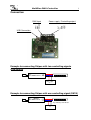
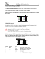
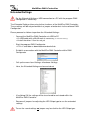
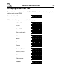
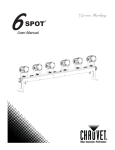
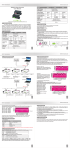
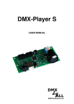
MultiPixx DMX-Controller
User Manual
MultiPixx DMX-Controller
Description
The MultiPixx DMX-Controller is especially designed for controlling digital LED
Stripes or Pixel Stripes whereas each single LED is individually controllable.
By controlling via DMX the interface can controll 170 individually pixels (RGB).
So, running lights, gradients up to rainbow effects can be created.
The output is construed for connecting several digital LED Stripe types.
Due to the adjustable output-protocol this controller is applicable universal.
The MultiPixx DMX controller supports pixel groups with an adjustable length. Each
pixelgroup is controlled by 3 dmx channels on the same way as a single pixel. Thus,
longer digital LED Stripes with more than 170 pixels can be controlled.<br>
An integrated update possibility allows controlling prospective LED Stripes.
Data sheet
Power supply:
5 - 12V DC / 100mA or via an USB-connection
DMX-IN:
up to 512 DMX-channels
Output:
Digital controlling signal for up to 170 RGB-Pixel
individually
Output protocol:
MagiarLED III flex, TM1804, TM1812, TM1829,
WS2801, LPD8803, DycoLED, UCS1903, UCS9812,
WS2811, WS2812, WS2812B, INK1002, INK1003,
APA-101, APA-102, APA-104, LPD6803,
LPD1886 8Bit, LPD1886 12Bit, UCS2912 RGBW
(Adjustable via jumper)
Color sequence:
Adjustable
Pixelgroups:
Adjustable (1 – 25 pixel)
Maximum Pixel / Pixelgroups:
Demo programs:
170 Pixel
DMX-Mode:
170 Pixel
512 Pixel
Dimensions:
(RGB-Stripe)
(SingleColor-Stripe)
58 x 54 x 14mm
2
MultiPixx DMX-Controller
3
Connection
Power supply / Controlling output
DATA
CLK
GND
PWR –
PWR +
DMX +
DMX DMX GND
DMX-Input
USB-Connection
DMX
Example for connecting Stripes with two controlling signals
(CLK+DATA)
PWR+
DMX +
MultiPixx
CLK
DMX DMX G DMX-Controller DATA
GND
MagiarLED III flex Stripe
+
-
Netzteil
Power
supply
5V
5V
DMX
Example for connecting Stripes with one controlling signal (DATA)
DMX +
MultiPixx
DMX DMX G DMX-Controller
V+
DATA
GND
z.B. LED-Stripe mit TM1804
E.g. LED-Stripe with TM1804
+
-
Power
supply
Netzteil
5V
5V
MultiPixx DMX-Controller
4
DMX-Addressing
The DMX-Starting address is adjustable via button 1 to 9.
Thereby switch 1 has the valency 20 (=1), switch 2 the valency 21 (=2) and so on until
switch 9 has the valency 28 (=256). The switches showing ON represent in sum the
starting address.
1
2
4
8
16
32
64
128
256
OFF
Switch 10 is reserved for the demo programs and must show OFF during the DMXoperation.
LED-Display-Codes
The integrated LED is a multifunctional display.
During the DMX-operation the LED lights permanently.
Furthermore the events will be signalled via the LED. In this case the LED lights
up in short pitches and hold off for a longer time. The number of flashing lights
corresponds to the event number:
Event
number
1
2
Error
Description
No DMX-Signal
Addressing error
3
DMX-Signal error
There is no DMX signal detected
Please check, if a valid DMX-starting address is
adjusted via the DIP-switch
An unvalid DMX-input signal is detected. Interchange
the signal circuit at the pin 2 and 3 or use w twisted
connecting wire.
MultiPixx DMX-Controller
Adjust the LED Stripe type
The type of the used digital LED stripes is adjustable as follows via a jumper:
Extended Settings are used
MagiarLED III flex
LPD1886 12 Bit
LPD1886 8 Bit
LPD1886 12 Bit – SingleColor
DycoLED / APA-101 / LPD6803
TM1804
WS2801
WS2811 / WS2812 / WS2812B / APA-104
INK1002 / INK1003
LPD8806
UCS1903
APA 102
TM1812
TM1829
UCS9812 (8-Bit Ctrl)
UCS9812 (16-Bit Ctrl)
UCS2912 – RGBW
5
MultiPixx DMX-Controller
6
Pixel Controlling via DMX
The MultiPixx DMX-Controller controls each RGB-Pixel with 3 DMX-channels.
Each single DMX-channel will be used for red, green and blue.
Beginning with the starting address the DMX-channels will be automatically assigned
to the Pixel:
Pixel 3 - R
Pixel 2 - B
Pixel 2 - G
Pixel 2 - R
Pixel 1 - B
Pixel 1 - G
Pixel 1 - R
Starting address
Startadresse
DMX MODE-channel
An additional MODE-channel can be activated to constitute Pixel-groups (pixel
sections) and to call up the demo programs via DMX.
Activate the MODE-channel via the Extended Settings
( Enable Mode-Channel).
Please take further details from chapter Extended settings
With the activated MODE-channel determines the DMX-channel 1 the pixel sections
length with the same color (DMX-value 1-127), thereby the maximum length is 127
pixels. The following DMX-addresses are meant for the color-settings. Thereby every
single DMX-channel exists for red, green and blue.
Channel
1
Function
Mode
2
3
4
:::
Color
Value
0
1-127
128-255
0-255
0-255
0-255
:::
Pixel 3 - R
Pixel 2 - B
Pixel 2 - G
Pixel 2 - R
Pixel 1 - B
Pixel 1 - G
Pixel 1 - R
Mode
Starting address
Startadresse
Pixel sections length = all pixel
DMX-value = pixel sections length
See demo program via DMX
Pixel 1 red
Pixel 1 green
Pixel 1 blue
:::
red/green/blue for each pixel
MultiPixx DMX-Controller
7
Extended Settings
For the Extended Settings a USB-connection to a PC with the program DMXConfigurator is necessary.
The Extended Settings allow using further functions of the MultiPixx DMX-Controller.
These settings will be not performed via a jumper or button but via the software DMXConfigurator.
Please proceed as follows to perform the Extended Settings:
-
Connect the MultiPixx DMX-Controller via USB to PC
A USB-cable with a MiniB-male is necessary (not included in delivery)
Install the driver if it exists not yet
-
Start the program DMX-Configurator
This is available as download www.dmx4all.de
-
Establish a connection with the MultiPixx DMX-Controller within DMXConfigurator
-
Call up the menu item Settings Hardware Settings
-
Here, the Extended Settings can be carried out
-
Via clicking OK the settings will be transferred to and stored within the
MultiPixx DMX-Controller
-
Remove all jumpers for adjusting the LED-Stripe type to use the extended
settings.
To use the saved settings no jumper may be stick for the LED-Stripe type.
MultiPixx DMX-Controller
Pixelgroups
Pixelgroups are supported in the firmware V1.03 or higher.
If necessary, make a firmware update.
For the configuration the DMX-Configurator V2.0.7 or higher is needed !
The MultiPixx DMX-Controller support pixelgroups with a adjustable length. The
length is set by usiong the extended settings.
Each pixelgroup is controlled by 3 dmx channels on the same way as a single pixel.
The maximum pixel count which can be connected depends on the selected LED
protocol:
LED-Protocol
MagiarLED III
MagiarLED II
Dyco LED / APA-101
TM1804
TM1812
TM1829
WS2801
LPD8803
LPD6803
UCS1903
APA-102
WS2811
WS2812 / WS2812B
UCS9812 (8Bit Ctrl.)
UCS9812 (16Bit Ctrl.)
LPD1886 8Bit
LPD1886 12Bit
LPD1886 12Bit SingleColor
UCS2912 - RGBW
max.
Pixel/Pixelgroups
170
170
170
170
170
170
170
170
170
170
170
170
170
170
170
170
170
512
128
max.
connected Pixel
2048
4098
4098
683
683
683
2733
2733
4098
341
2048
683
683
390
390
911
683
683
512
8
MultiPixx DMX-Controller
Demo programs via DMX
Activate the MODE-channel in the Extended Settings to use this function
( Enable Mode-Channel).
Please take further details from chapter Extended Settings.
The predefined demo programs in the MultiPixx DMX-Controller can be called up
via the DMX-channel 1 (MODE-channel) from a DMX-value 128. The speed is
adjustable via DMX-channel 2.
Channel
1
Function
Mode
2
Color
3
3
3
3
3
3
3
Speed
Value
0-127
128-135
136-143
144-151
152-165
166-177
178-189
190-203
204-217
218-231
232-239
240-246
247-255
0-31
32-63
64-95
96-127
128-159
160-191
192-223
224-255
0-255
See Pixel Controlling via DMX
8 color mix
R-G-B
RGB color star
Single color star
Wave 1
Wave 2
Snake
Fecher
Running Point 1
Running point 2
Blink
Rainbow
White
Red
Green
Blue
Yellow
Pink
Cyan
(Off)
Fast → Slow
9
MultiPixx DMX-Controller
10
Demo programs without DMX
The existing demo programs in the MultiPixx DMX-Controller can be called up via the
switches and without DMX.
Set switch 10 on ON:
ON
OFF
1
2
3
4
5
6
7
8
9
10
With switches 1 to 4 you can select the demo program.
ON
8-Color Mix
OFF
R-G-B
OFF
Stars RGB
OFF
Stars single color
OFF
Wave 1
OFF
Wave 2
OFF
Snake
OFF
Fecher
OFF
Running Point 1
OFF
Running Point 2
OFF
Blink
OFF
Color change
OFF
Rainbow
OFF
1
2
3
4
5
6
7
8
9
10
1
2
3
4
5
6
7
8
9
10
1
2
3
4
5
6
7
8
9
10
1
2
3
4
5
6
7
8
9
10
1
2
3
4
5
6
7
8
9
10
1
2
3
4
5
6
7
8
9
10
1
2
3
4
5
6
7
8
9
10
1
2
3
4
5
6
7
8
9
10
1
2
3
4
5
6
7
8
9
10
1
2
3
4
5
6
7
8
9
10
1
2
3
4
5
6
7
8
9
10
1
2
3
4
5
6
7
8
9
10
1
2
3
4
5
6
7
8
9
10
ON
ON
ON
ON
ON
ON
ON
ON
ON
ON
ON
ON
MultiPixx DMX-Controller
11
With switch 5, 6 and 7 the color will be selected.
ON
White
OFF
Red
OFF
Green
OFF
Blue
OFF
Yellow
OFF
Pink
OFF
Cyan
OFF
Black
OFF
1
2
3
4
5
6
7
8
9
10
1
2
3
4
5
6
7
8
9
10
1
2
3
4
5
6
7
8
9
10
1
2
3
4
5
6
7
8
9
10
1
2
3
4
5
6
7
8
9
10
1
2
3
4
5
6
7
8
9
10
1
2
3
4
5
6
7
8
9
10
1
2
3
4
5
6
7
8
9
10
1
2
3
4
5
6
7
8
9
10
1
2
3
4
5
6
7
8
9
10
1
2
3
4
5
6
7
8
9
10
1
2
3
4
5
6
7
8
9
10
ON
ON
ON
ON
ON
ON
ON
With switch 8 and 9 the speed will be adjusted.
ON
Slow
OFF
ON
OFF
ON
OFF
Fast
ON
OFF
MultiPixx DMX-Controller
Execute the Firmware update
The MultiPixx DMX-Controller has an update-function which allows transferring
prospective Firmware-versions.
Please proceed as follows:
-
Turn off device
-
Stick jumper as shown
-
Turn on device
-
Establish USB-connection to PC
-
Start the update-software DMX4ALL USB-Updater
-
Select the MultiPixx DMX-Controller Interface from the list
-
Click Firmware-Update
-
Select and confirm the Firmware-file (.bin)
-
Please wait until the update is finished.
If an error occurs during the update you can begin from the start any time.
12
MultiPixx DMX-Controller
Accessory
Digital LED Stripes / Pixel Stripes
- MagiarLED III flex Stripe 72
- MagiarLED III flex Stripe 144
- Digital LED Stripe WS2811
- Digital LED Stripe WS2812
- Digital LED Stripe LPD1886
Power supply 5 V / 6A
USB-cable A-male MiniB-male
13
MultiPixx DMX-Controller
14
CE-conformity
This assembly (board) is controlled by a microprocessor and
uses high frequency (8MHz). To get the characteristics of the
assembly in relation to the CE-conformity, an installation in a
compact metal casing is necessary.
Risk-Notes
You purchased a technical product. Conformable to the best available technology the
following risks should not excluded:
Failure risk: The device can drop out partially or completely at any time without
warning. To reduce the probability of a failure a redundant system structure is
necessary.
Initiation risk: For the installation of the board, the board must be connected and
adjusted to foreign components according to the device paperwork. This work can
only be done by qualified personnel, which read the full device paperwork and
understand it.
Operating risk: The Change or the operation under special conditions of the
installed systems/components could as well as hidden defects cause to breakdown
within the running time.
Misusage risk: Any nonstandard use could cause incalculable risks and is not
allowed.
Warning: It is not allowed to use the device in an operation, where the safety of persons
depend on this device.
DMX4ALL GmbH
Reiterweg 2A
D-44869 Bochum
Germany
© Copyright 2014 DMX4ALL GmbH
All rights reserve. No part of this manual may be reproduced in any form (photocopy, pressure, microfilm or in another
procedure) without written permission or processed, multiplied or spread using electronic systems.
All information contained in this manual was arranged with largest care and after best knowledge. Nevertheless errors are to be
excluded not completely. For this reason I see myself compelled to point out that I can take over neither a warranty nor the
legal responsibility or any adhesion for consequences, which decrease/go back to incorrect data. This document does not
contain assured characteristics. The guidance and the characteristics can be changed at any time and without previous
announcement.