1
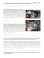
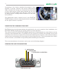
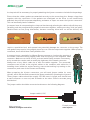
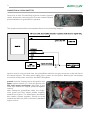
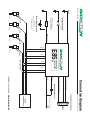
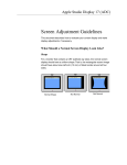
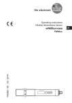
E85
programmable
conversion
kit
SERVICE MANUAL
recommended by the
Hungarian Bioethanol Association
www.bioetun.com
1.
THEORETICAL DIAGRAM
computer
E85 mode switch
BioETUN
E85
CONVERSION
KIT
communication wire
engine
management
system
ground
NTC
temperature
sensor
injectors
engine
heater pipe
Original engine
temperature sensor
MINIMUM TOOL REQUIREMENTS FOR INSTALLATION
•
•
•
•
•
•
•
•
•
digital multimeter (for ohm and voltage measurements)
LED break detector (for injector control)
soldering iron
insulation tape, shrink tube
pliers
crimp tool for the injector connections
tools for opening the car’s dashboard engine housing
PC compatible computer, Windows XP operating system, serial port
if no serial port is available, usb-rs232 converter
INSTALLATION PROCEDURE
Step 1: The measurements:
Measuring injector resistance
The BioETUN 1-4 electronic system is used for the conversion of central- or single cylinder injection automobiles to
use E85 fuel. The resistance of the injectors must be measured in all cases, using a simple multimeter. For central injection engines, the system can only be used for controlling
2.
injectors above 3 ohms, while for central injection engines, only injectors above 10 ohms can accommodate the system. (Details for the conversion of the first-generation Suzuki Swift central injection
model are described in a separate document, available at e85tuning.hu, under the Downloads menu)
Determining the injector control signal.
Two cables are attached to the injector, through the connectors. Generally, one of them will be +12V, while the other is the negative control signal. BioETUN 1-4 processes
and forwards the negative signal, making it important to
determine which is the control cable before conversion. A
LED break detector, for example, is an appropriate tool for
this. (Warning! A detector with an incandescent light bulb
should not be used, because the factory electronics can interpret the incandescent bulb as a short circuit, leading to
the possibility of a malfunction.)
Measuring thermostat voltage
The BioETUN 1-4 electronic system can operate with the
included NTC heat sensor, in which case further measurements are unnecessary. However, connecting to the car’s
factory standard 5V heat sensor is also possible. For the
first option, the orange cable should be used, while for the
second, the white/orange cable; the electronics should be
programmed accordingly via the BioETUN Tuner software.
If you wish to perform temperature measurements connected to the factory-standard thermostat, then you will
need to find the thermostat wire where 0-5V voltage is present, between cold and hot operation. If there are several
thermostats, or one combined thermostat, you will need to
find the 5V system in all cases.
Step 2: Connecting the electronic system, wiring
The BioETUN 1-4 system is capable of independently controlling a maximum of 1-4 cylinders. The device is agnostic to the exact sequence in which the cylinders are connected, but it performs measurements on Channel 1 (black/green - green wire;) hence, that channel needs to be connected in all cases.
The wires connecting to the factory standard electronics are always dual colored (for example, black/
yellow,) while the wires connecting to the injectors are single colored (for example, yellow.)
The connectors included with the electronic system are composed of plastic housing, rubber gaskets, and connecting pins. It is best to use a crimp tool to attach the pins to the cables, then connect
them according to the control pin schematics. Do not forget the rubber gaskets, as they serve to
guarantee long-term, oxidation-free operation for the connectors. Power supply for the electronic
system is via +12V ignition switch only. Thorough grounding and an appropriate, continuous power
supply is a must, even when jump-starting. We suggest that you download the service documents
before attempting to connect the electronic system: they are available at e85tuning.hu, under the
Downloads menu. (username: e85, password: tuning)
While the device is dust- and moisture resistant, we suggest installing it inside the cabin, for instance under the dashboard. Should this not be practicable, it should be installed inside the engine
compartment, protected from water, and fixed in place with cable combiners. The device is heatresistant up to 85 degrees Celsius, but must not be installed near sources of radiating heat, such as
the turbo or exhaust knee.
2.
Optionally, the BioETUN 1-4 electronics warning light can also be installed. The warning light may
be a LED or an incandescent bulb of no more than 5 A amperage. The warning light’s operation is
detailed in the program description.
Switching the purple wire of the mode switcher to ground, the programmed E85 mode will activate.
The switch will light up when switched on, so we suggest connecting an ignition-switched +12V next
to the switch. The device has a default program, meaning that the car should start with the installed
electronics system without need for any further programming.
CONNECTING THE SWITCH
The switch included in the package is capable of signaling E85 mode. When active, it lights up green.
To connect it, you will need ignition-switched +12V, ground, and the connecting wire for the BioETUN
1-4 electronics system (purple wire.)
It is a good idea to ensure adequate power supply before installation, possibly via connecting a
separate cable off the red (+12V) or the black (ground) wires of the BioETUN electronics system.
The switch should be connected as shown on the following diagram:
ignition +12V
to switch
ground
CONNECTING THE HEAT SENSOR
The NTC heat sensor included with the package is used to monitor the system’s temperature. Using
the basic configuration, the cable set is meant for this sensor. The orange cable should be connected
to one of the wires, while the ground should be connected to the other. The wire colors are irrelevant,
you can solder to any of the prongs; proper grounding is, however, very important. The heat sensor
should ideally be affixed to the heating tube with cable ties. It is important to ensure that the sensor
not be cooled by air movement during driving. To this end, wrapping it in a thermally resistant and
insulating material may be worthwhile.
3.
Connecting to the factory standard thermostat is also
possible. To do this, connect to the shorter white/orange
cable, instead of the orange one. Almost all cars have two
or more heat sensors; some types integrate the two into
a single thermostat. Make sure that you connect to the
5V factory sensor. Voltage should be above 4V cold, and
around 0V hot.
The appropriate sensor should be set in the BioETUN
TUNER program, with the cold start parameters optimized
for the type of sensor in question.
CONNECTING THE COMMUNICATIONS PORT
BioETUN devices should almost always be optimized for the car in question. After installation, the
BioETUN TUNER program can be used to monitor precise operation.
The newest version of the BioETUN TUNER program can be downloaded from www.bioetun.com by
clicking on the Download menu. The DSUB9-es 9-pin connector included in the package can be used
to connect to the electronic system. Be careful when attaching the connector; most communications
malfunctions are caused by not connecting all of the prongs correctly. The prong numbers are visible
on the connector; this should be of great help when attaching the connector.
The correct attachment of connector can be seen on the following diagram:
ICRIMPING THE INJECTOR CONNECTORS
2 - white/yellow
3 - white/brown
5 -black/white or white/blue
soldered side view
4.
A crimp tool will be necessary for properly attaching the injector connectors included in the package.
Ensure that the rubber gaskets are attached securely to the connecting pins. Always crimp them
together with the connectors. If the gaskets are misaligned on the wires or are insufficiently
attached, they will fail to operate adequately, and water or vapor can enter the injector connectors.
This can eventually lead to oxidation.
A common issue is not squeezing the crimp tool hard enough, allowing the cable to slip off the prong.
Carefully push the prongs and the prepared connectors together, making sure they click into place.
Double-check correct prong distribution, because removing them later on will be difficult, will
require a specialized tool, and removal can potentially damage the connector or the prongs. The
new gaskets may require using slightly more force to click the components together. When properly
connected, there should be a clearly audible click.
A common issue—especially for Nippon Denso connectors—involves the opening of
the female connectors being slightly wider than the prong of the respective male
connector. Make sure to check for this, as it can lead to faulty contacts. If necessary,
a tiny screwdriver can be used to modify the tightness of the female connector.
Always use a furry fabric cable tie to affix the cables together. The connected
connectors can be tied to the original cables or the combiner with cable ties. If
installing them inside the engine housing, ensure that nothing is pressing on the
connections, and none of the contact are vibrating.
When preparing the injector connectors, you will need jumper cables for every
cylinder, which will be used to transmit the power needed for operating the injectors.
These jumper cables should be roughly 150-200 mms in length, and should have
a male connector on one end, and a female on the other. Ensure accurate prong
distribution!
The jumper cables should be connected as shown on the following diagram:
Jumper cable (+12V)
Male connector
towards an engine controller
Female connector
onto injector
5.
CONNECTING A SUZUKI SWIFT TBI
Control for a Swift Throttle Body Injection (central injection)
can be achieved by connecting the first two channels (black/
green+black/blue or green/blue) in parallel.
The components should be connected as shown on the following diagram:
Injector control: from a frontal view, the yellow/black cable for the grey connector on the left side of
the central injector. The other yellow cable is the + power for the injector. Warning: do not attempt
to use this as the power source for the BioETUN system!
ground: from the firewall, next to the ignition coil
power: ignition switch +12 V from the ignition coil
NTC heat sensor positioning: cable-tied to the
water pipe behind the engine, protected against
cooling.
After cutting the yellow/black cable, the singlecolor green and blue cables twisted together
towards the injector. The black/green and black/
blue cables, twisted together, should be wired
towards the cable set, that is, the factory standard
engine control.
E85
+12V
blue
programmable
conversion
kit
grey
black/yellow
yellow
wire connection
black/grey
black
purple
AD1 orange
+12V
Injector
black/blue
MADE IN HUNGARY
Body
+12V
Injector
black/green
Configuration switch
(included in package)
NTC heat sensorr
(included in package)
+12V
Injector
Factory engine thermostat
(optional)
NOTE: Only one of the two
can be selected
Injector
green
+
DSUB9
+12V
ignition switch (15)
5
3
2
Communications connector
For a 4-injector vehicle
Connection diagram
white/yellow or white
white/brown or red/white
-
Mode display light (LED)
black/white or white/blue
brown
red
factory
engine control
további információ: www.bioetun.hu