1
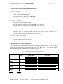
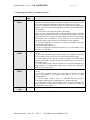
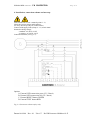
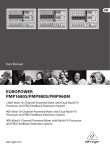
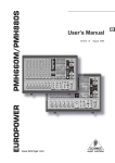
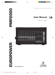
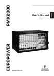
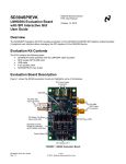
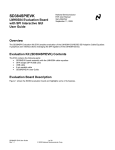
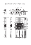
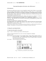
EUROPOWER MANUAL
IB PROTECTOR
Pag.1/5
Functional description of the safety relay ‘IB Protector’
0. Introduction
The safety relay IB Protector protects users and appliances against electric failures in a non-earthed
mains (IU-mains) through insulation resistance protection. It makes the use of an earth leakage
protection redundant. This makes it very useful in combination with mobile gensets because the
generator (phase earthing or neutral point earthing) does not have to be earthed by means of an earth
pin in the ground. In case a failure occurs, the safety relay IB Protector will disconnect the generator
voltage through an external power relay.
The insulation resistance between the ground conductor (PE) and the live conductors is measured
continuously. The detection threshold can be preset between 30kOhm and 120kOhm.
Moreover, several extra functions can be installed: over- or undervoltage, frequency that is too high
or too low. These functions can be activated or deactivated by the manufacturer by means of an
internal DIP switch.
The safety relay IB Protector is equipped with 2 switches.
An insulation failure can be simulated by means of a 'test' switch. The safety relay can be activated
again through the 'reset' switch. The activation of the power relay can be protected against
‘undesired use’ by means of a secret code.
At each start, a self-test is done. First, the power relay is checked (e.g. failure caused by sticking or
bridging). Subsequently, an insulation failure is simulated to check the safety relay.
1. Setting the operating functions
1.1 Operation through the front panel
Figure 1.3 shows a schematic representation of the front panel.
Insulation threshold (insulation level): can be set between 30kOhm and 120kOhm
(tolerance ± 10%).
'Reset'-switch: reset after detection of an insulation failure, voltage failure, frequency failure or
power relay failure. If the optional protection against “undesired use” has been
activated, press the ‘reset’-switch for more or less 5 seconds in order to activate the
safety relay (green LED lights up).
'Test'-switch: causes an insulation failure for self-test.
Fig. 1.3 Schematic representation of the front panel
Datum:16/09/04
Rev.: 01
Uitv:CC
Ref: IB Protector-080904rev01-E
EUROPOWER MANUAL
IB PROTECTOR
Pag.2/5
1.2 Functions to be activated by the manufacturer
1.2.1 option “voltage”
Voltage protection (standard setting):
The lower limit of the voltage is set at 175 Volt.
The upper limit of the voltage is set at 285 Volt.
The alarm starts when the safety limit has been exceeded during 2 s.
1.2.2 option “frequency”
Frequency protection (standard setting):
The lower limit of the frequency is set at 42.5 Hz (-15 % of 50 Hz).
The upper limit of the frequency is set at 57.5 Hz (+15 % of 50 Hz).
The alarm starts when the safety limit has been exceeded during 20 ms.
1.2.3 option “protection against undesired use”
The safety relay is delivered with an inactivated protection against “undesired use”.
At request (when ordered), this protection can be activated.
1.2.4 option “power relay control”
Standard setting: power relay control activated.
At request (when ordered): not activated.
2. Description of the failure indications
A green and a red LED on the front panel indicate the condition of the safety relay. In case a failure
occurs, the red LED shall be activated and the green LED shall go out. The different failure
indications through LED combinations can be found in figure 2.3.
Fig. 2.3: LED indication when failure occurs
Failure
code
Indication
green LED
Indication
red LED
No failures
Insulation
failure
Voltage failure
I
Frequency
failure
Power relay
failure
F
on
Datum:16/09/04
S
C
off
Rev.: 01
Uitv:CC
Ref: IB Protector-080904rev01-E
EUROPOWER MANUAL
IB PROTECTOR
Pag.3/5
3. Operating procedure for failure detection
Description
Insulation
failure
Failure
code
I
Voltage
failure
S
Frequency
failure
F
Failure power
relay
C
Datum:16/09/04
Rev.: 01
Actions to be taken
1. When an insulation failure takes place, stop the genset and find the
cause of the insulation failure. When the situation is safe again, start the
genset again and check whether the insulation failure occurs again.
2. If the insulation failure takes place a second time, disconnect the
charge, press the 'reset' button and check whether the insulation failure
occurs again.
2.a. If not, there is in insulation failure in the charge:
Then you can systematically connect different charges until you find the
charge with the insulation failure. Or: disconnect the charges from the
genset and check the resistance of each charge between the earth and the
mains phase with a multimeter. If you measure a low resistance with
one of the charges, then contact the manufacturer of the appliance.
2.b. If it does, then there is a genset or a safety relay failure: contact the
manufacturer of the genset.
3. Does the failure often occur?
If it does, regulate the insulation threshold in a way that makes it less
sensitive, e.g. 30kOhm.
1. Disconnect the charge and check whether the voltage failure still
occurs.
1.a. If it does, check the engine speed: when it is too high this will result
in overvoltage, when it is too low, this will result in undervoltage.
1.b. If the engine speed is OK, the genset is probably overloaded, which
causes undervoltage. Reduce the load or spread it better (in case of a
three-phase load).
1.c. If the engine speed is OK and if there is no overload, then there is a
genset failure or a failure of the safety relay. In this case, contact the
manufacturer of the genset.
1. Disconnect the charge and check whether the frequency failure still
occurs.
1.a. If it does, check the engine speed: An engine speed that is too high
causes overfrequency, an engine speed that is too low causes
underfrequency.
1.b. If the engine speed is OK, it is probable that the genset is
overloaded, which results in underfrequency. Reduce the load.
1.c. If the engine speed is OK and if there is no overload, then there is a
genset failure or a failure in the safety relay. In this case, contact the
manufacturer of the genset.
The power relay does not work properly, replace it as soon as possible!
Uitv:CC
Ref: IB Protector-080904rev01-E
EUROPOWER MANUAL
IB PROTECTOR
4. Installation, connection scheme and start-up
First read the above user’s manual (point 0 - 3).
Check the system voltage and frequency.
Use only one safety relay for each IU mains.
Connect with supply leads (clamp 2 - 13) of min.1mm².
Nominal working voltage:
- standard: AC 50 Hz 230V
- at request: AC 60 Hz 230V
Connection scheme (see fig. 3.3):
Options
A. External LED connection green (2V / 20mA)
B. External LED connection red (2V / 20mA)
C. External RESET button GREEN
D. External TEST button RED
Fig. 3.3 Connection scheme safety relay
Datum:16/09/04
Rev.: 01
Uitv:CC
Ref: IB Protector-080904rev01-E
Pag.4/5
EUROPOWER MANUAL
IB PROTECTOR
5. Technical data CE
Safety relay according to IEC 61557-8 (1997-02).
Voltage protection according to IEC 61557-1 (1997-02).
- overvoltage category II
Own consumption: 1.8 VA max.
Rated voltage Un:
- AC 50 Hz 230 V
Switch component (1 make-and-break contact):
- max. voltage: AC 250 V
- max. rated current: 8 A
- life span: switches > 30x106
- vibration durability: 20 g (30-150 Hz)
External output 5-6 and 5-7: max. 2V/20mA
Environmental temperature: - 25... + 60 °C
Storage temperature: -40...+70 °C
Protection: IP 20
Weight: 225 g
Insulation co-ordination according to IEC 664-1 (1992-10)
- installation category: III
- pollution degree: 3
- 'rated insulation voltage': AC 250 V
- 'rated impulse withstand voltage': 4 kV
Electro-magnetic compatibility (EMC) according to:
- IEC 61326-1 (1997-02)
- EN 50082-1&2 (also for industrial use)
Safety according to IEC 1010-1 (1990-09).
Datum:16/09/04
Rev.: 01
Uitv:CC
Ref: IB Protector-080904rev01-E
Pag.5/5