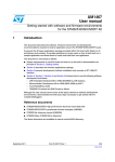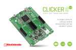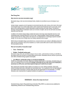
1
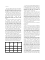
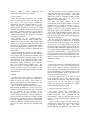
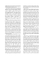
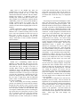
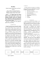
BroBot Richard Landau, Sarah Patten, and Jacob Stewart Dept. of Electrical Engineering and Computer Science, University of Central Florida, Orlando, Florida, 32816-2450 Abstract — An original electrical and computer engineering project combining aspects from several different elements, BroBot combines computer vision techniques, embedded design, and smartphone application development in a practical way. This project uses a small camera to watch an area, analyze it for changes, and report the results along with the picture to the user on his or her phone via a Bluetooth connection for security and peace of mind. Index Terms — Computer vision, security, Bluetooth, digital cameras, programming I. INTRODUCTION Designed to aid students with their studies, BroBot is a small, portable robot with the ability to offer his user a previously-unknown sense of security when studying alone in a public setting. When the user requires a break from their studies for any reason, he or she can simply set down BroBot, connect to him from a smartphone, and go about business, comfortable with the knowledge that his or her belongings are only a glance away, and that BroBot’s security system will notify both the users and passersby upon any theft. BroBot’s camera feeds into an STM32F407 microcontroller, which has code running that analyzes the images for significant changes in a short time frame, signaling a breach of security. It includes an on-board alarm to scare off thieves and alert nearby students who may be able to help, as well as an RN-41 Bluetooth module maintaining a connection to the user’s phone. Pictures are constantly streamed over this link to the phone, so the user need only turn on the phone to see a recent image of the location. If BroBot senses a security breach, the phone vibrates constantly until disabled by the user, allowing him or her to rush back to guard the location or indicate that it is a false alarm from the phone. Figure 1: Signal Flow A. Objectives To achieve the ideas we wanted to, we needed to create a detailed list of accomplishments we intended for BroBot to do within the time frame of our project. The list of objectives is as followed: Detect theft of an object Alert user when a theft has occurred Have an audible alert Be reliable and simple to use Have easily replaceable batteries Lightweight Portable Affordable II. HARDWARE At the heart of our project is the hardware. The hardware is responsible for taking a picture of the items, sending that picture to the user, receiving instructions from the user, and doing all the needed calculations on the images. The processor that we use must be able to complete all the necessary tasks while being a somewhat low powered microcontroller. Along with a processor we need a camera that can give us a photo that is easily stored and/or easily manipulated. All of these different components need to be easily tested so to ensure no complications during the building phase of our prototype. Therefore a strong emphasis of development board prices influenced what processer and module we decided to use. Figure 1 shows the flow of information in the system. The microcontroller deals with all communications in the system, it receives instructions from the user via the Bluetooth connection. The processor also instructs and deals with the camera. While the flow of information is very simple is depends on the microcontroller to a great degree, meaning the firmware on the microcontroller needs to be written we great caution. To bring our prototype to reality we need to have some type of power system that will give a good lifetime while being either replaceable or rechargeable for a normal user. Overall, all of the hardware decisions were made with the ideas of simplicity and frugality. A. Camera The main component which the entire hardware was designed around was the camera. This was to ensure that we could do all the necessary actions with the images and still have enough power to do everything else we want to do in the system. If it be converting, storing, or sending the image to the user. The camera needs to be able to interface with a microcontroller easily and also take demands from a microcontroller, preferably with using some type of simple serial protocol. Along with the aforementioned demands we need a small, inexpensive camera to keep with the theme of our project. With all of these demands in mind we decided to use uCAM-II Serial Camera Module. All communications to this camera are done on a UART 8 bit data transmission, through the RX and TX pins. The control on the camera is pretty versatile, and has all the functionality desired. Through the communication we are able to change the resolution of the picture between four different formats, three for RAWs and JPEG. The camera has the option of four different RAW resolutions, and three JPEG resolutions, and the ability to change the baud rate. Since the picture itself is sent over the serial line a lot of time is spent sending the picture. This problem can be remedied by decreasing the picture size coming out of the camera on the UART line. There are 15 possible different image types and resolution combinations, but JPEGS are the primary focus. Table 1 was produced by taking a sample of 100 different pictures of each resolution. This information is sent from the camera to the microcontroller via an UART command. When a command to take a picture is given, the camera sends an acknowledgement to verify that it correctly understood what picture was being asked for, and then the information is sent as a constant string after the end of the communications. Resolution Minimum Value Maximum Value (Average) (Average) 160x120 2136 2786 2542 320x240 5324 8976 7523 640x480 11542 13480 12478 Table 1 Average Value To work properly with the android application we decided to use the JPEG 320x240 resolution when we are refreshing the picture for the user. While when we are doing the actual item watching we are using 8-bit Gray Scale RAW images of size 80x60. The justifications for this size are discussed in “Interfacing and other considerations”. When ordering the camera, there were a few different options for the lens. The one that comes with the camera normally is a 56 degree lens. The other two options for the lens were an extra cost, and the main desire was to be able to have an image that’s viewable; it doesn’t have to be perfectly clear. Upon testing the lens and sending images, the focal range for the detection would need to be detected. If the objects that are being watched were 0.3 meters away, the camera would be able to gain a clear focus from 0.28 meters to 0.33. After the desired focus is found, it can be secured with the lock nut. The distance the camera needs to be from the items is about 50 cm. B. Bluetooth Since we knew that we wanted to communicate with the user via an android application we only had two different options for a type of wireless; Bluetooth and Wi-Fi. Keeping with the theme of simplicity we went with Bluetooth, since most common phone users have had prior experience with the technology. We wanted to pick a Bluetooth module that was simplistic and could be controlled via a serial line from a microcontroller. We needed the module to easily work with an android phone, and not have a lot of hoops that the user would have to jump through. Also to meet our ranges we went with a class 1 module, which has a range up to 100m. Microchip’s RN-41 is the module that we picked to use for our project. While there are quite a number of very similar modules we decided upon the RN41 because of prior experience working with the module, and its ease of use. This module is fully contained with no need of external components and is controlled via an UART line. To easily mesh with an Android phone the module only needs to be powered and connected to a serial line. Less than a second after powering up, the module will go into a full function mode where anything that is received on the module, via a BT connection, will be sent on the serial line. While anything sent on the Rx line of the module will be sent on the BT connection, as long as one is already established. The module runs off 3.3 Volts and comes in a surface mount package. So not to create unwanted noise in the Bluetooth connection the antenna on the module has to protrude off the board with nothing below it. While in normal configuration and connected the module pulls up to 160mA. C. Microcontroller Once those two major components were decided upon we wanted to find a microcontroller that will meet all of our prior image manipulation requirements and have enough memory to store multiple JPEG files. Because of the computation power required we wanted to look for an ARM processor that met our demands but also met out price range. With this in mind we were somewhat limited on what we could get, since a Beagle Bone or a Raspberry-pi would be too expensive to reproduce on a printed circuit board. We decided to use STMicroelectronics’ STM32F407 microcontroller, which is a M4 cortex ARM processor that has some DSP heritage while sporting all of the pluses of ARM architecture. The processor was created for use in small digital cameras and portable music players, which is perfect for our project since we need to be able to manipulate and store pictures. The STM32F407 has 1 megabyte of flash memory, 192Kbytes of RAM, and runs on 3.3V. The controller comes with a built in interfaces of common serial communication protocols including UART, I2C, SPI. We decided to use the LQFP100 package for our PCB, since that is the package that comes on the development board, meaning the code would not have to be changed when switching over. The processor runs at a 168 MHz clock, which is fast enough for what we want to accomplish. It also comes with 2 DACs which will be used for our alarm implementation. D. Sound A simple way to deter thefts is to implement a simple alarm that will trigger when something is stolen in front of the camera. All we need is a speaker and something to produce a sine wave that can be manipulated to sound like an alarm. We use the 12-bit digital to analog converter that is built inside the STM32F407 to create a sine wave. The DAC runs off an internal timer that is controlled via an interrupt in the software on the microcontroller. By changing the timing we can produce different frequencies, with this method we only get one tone out of the DAC, but this is perfect for an alarm system that isn’t meant to sound pleasant to the ear. Normally alarm systems are in the higher frequencies, therefore our alarm starts at about 1k Hz and goes up to 2Hz, and will loop throughout that range. The direct memory access commands are used while doing this alarm; this is to ensure a clear sound coming out of the microcontroller. The DMA enables the ability to manipulate memory without using processor cycles; this is one of the main features of the ARM architecture. To make the signal coming out of the microcontroller loud enough to audible we need an amplifier before it reaches the speaker. Since we wanted a low power amplifier we chose a Class-D amplifier, which uses pulse width modulation to amplify the signal, using MOSFETs in saturation mode. Pulse width modulation coupled with a low pass filter, the speaker in this system, is perfect for what we want, a loud alarm where the sound quality doesn’t need to be spot on. We are using Texas Instrument’s TPA2005D1 since it is built with an 8 OHM speaker in mind and also boasts low power consumption. This amplifier can operate at a 3V-5V range while IC itself is very small and doesn’t take up much space on a PCB. We are using a single-ended input configuration with one of the inputs going to ground and the other going to the output of a potentiometer. The potentiometer is used to control the volume of the alarm and can only be changed from inside the box that holds the robot. This is to ensure that only the user can change the volume of the alarm. E. Power For this project there are two different voltage lines that are needed, 3.3V and 5V. We wanted the power supply of the system to either be rechargeable or easily replaceable, something that an everyday person can use and understand. For simplicity sake we went with two linear regulators, one at 3.3 the other at 5V, with 4 AA batteries as the source. The linear regulators that we are using are from Texas Instrument’s UA78 series, using the surface mount package for the PCB. These have an output current up to 500 mA and need no external components, which makes using them very simple and will integrate easily on our PCB. F. Interfacing and other considerations As stated earlier the STM32F407 is communicating with the camera and Bluetooth module using the UART peripheral on the microcontroller. Both are using the same protocol and the IO of the communication is handled in the same way. Since we know exactly how the camera will respond to any request sent to it there is no need for an interrupt to control the inputs. This makes programming the communication very simple and straight forward. We do not have the need to store the returned message since the most of the messages are just indications that something was sent. This approach would not work for the Bluetooth module, since we cannot predict when the application will send a request to the microcontroller. Because of this an interrupt is being used that will run whenever anything is picked up on the UART line from the Bluetooth module. This solution causes its own problems where a call can happen anytime something is going on in the program. While this isn’t much of a problem for most of the operations this is a huge problem if it happens while the microcontroller is talking to the camera. To circumvent this result we simply turn off this interrupt while the microcontroller is talking to the camera. It should be noted that receiving the picture from the camera took some testing to fully work. The communication with the camera is a highly specific process. Before anything can be communicated, the processor has to sync with the camera. This syncing doesn’t always happen on the first try, and can take up to 60 tries, though the average number of times it takes is between two and six. To handle this, a variable was set up, ACKBOOL that acts as a Boolean value, and becomes set once the syncing has completed. There is a loop that continues trying to sync, and once the camera responds with an ACK that they received the request to sync, and it sends another message to show its okay to sync, the loop is broken out of and ACKBOOL is set. The processor needs to respond with an acknowledgement after this to solidify the syncing. The communication is back and forth, so to get a picture from the camera, there is a specific sequence of requests and acknowledgements that need to be sent. To talk to the camera and request for it to take a JPEG image, a message must be sent to start the initial request, then set the package size, then another request that says get picture. After each of these messages to the camera, the camera will be sending back acknowledgements. Then when the camera is finally ready to start sending the picture, it breaks down the image into 512 byte packages, after each package, the user must send back an acknowledgement to verify the package was received. At the end of the data that is received, the processor must send a final acknowledgement. If this isn’t sent, the camera will be waiting for it, and no matter what else is sent after, if it isn’t the acknowledgement, that camera won’t know what is being sent, so nothing else will be able to happen. The process for requesting a RAW image is a lot simpler. There are only two initial messages, each receiving its appropriate acknowledgement, then after the third one, the camera sends the picture, then it sends the image data as the complete picture. Again after receiving the image, the user must send a final acknowledgement. When it was being determined what types of images should be used for the app and the computer vision portion of the project we had to keep in consideration the size of the file, the clarity, and the functionality. It was desired to have the user of the app receive JPEG images since they look nice to the user and aren’t large files. For the computer vision portion however, decoding JPEGs before getting to the actual functionality of the computer vision was taking up a lot of computing time and RAM space on the processor, as well as having to store JPEGs, it was decided that, if possible, it would be better to try to use raw images. Since we don’t need any color information, a gray scale image would be just as useful as a full colored image. The size of the RAW image will be as small as possible, so the 80x60 resolution is used. The file will always be the same size at 4800 bytes of data. This resolution was used because with a smaller resolution, the image processing can run faster, which will allow for more images to be processed, and a greater chance of detecting an error in a timely manner. So instead of just taking one picture and using it for the computer vision and the app, there will be two images taken. Every few seconds while BroBot is watching study materials, he will take a new image to check how much the scene has changed, and the microprocessor will also be communicating with the app. While it does this it will take and send JPEG images at the users’ request, and at a determined time interval. When the user is communicating with the camera to receive a JPEG image, one of the required messages that are sent is “SET PACKAGE SIZE”. This message determines how big of a package the user would like to take each time, with the max being 512 bytes. Since the pictures don’t always have the same size, modular arithmetic is done to figure out where the last piece of data will end up. Even if this isn’t the case, because the image is a JPEG, the last two bytes are guaranteed to be FF D9, so we would be able to find the end of the data. When the user wants another picture, it has to go through the long communication process again. This is useful because the image will always be new. There wouldn’t need to be any worry about the camera storing the picture and sending the same one multiple times, as it is the case for some cameras. Our PCB is a two layer board; one side is used for a ground plane while the other is used for most of the routes that are needed. Along with the needed modules we also put a section of 20 pins from the microcontroller in case a need arrives for them, for example test LEDs. A 5 pin ST-Link connector was put on the PCB so the microcontroller can easily be reprogrammed and tested using the development board. Finally a 5 pin header connection was put on the board so that the camera can be connected. This has the only trace from the 5V linear regulator, along with connecting the two UART pins from the microcontroller. The power supply of 4 AA batteries is held within a plastic battery holder with the leads going to a two pin header on the PCB. III. APPEARANCE Designing the appearance of BroBot required us to think about the way we wanted to transport him. Initially we intended for him to be easily portable in a backpack so students could easily bring him to the library. With this methodology, he would need to be small, lightweight, and easily portable. Initially we wanted him to have a small body with an expandable camera, almost like an old antenna or a telescope. While this was a nifty idea, it wasn’t plausible. We searched for something that fit the image we had in our minds, but that proved to be more difficult than we originally thought. Since this didn’t work, we began going to craft stores to find inspiration for our design. We knew in the end that we needed something that would allow for the camera to be adjusted to a position the user found desirable. After browsing a few stores, with nothing jumping out at us, the “neck” of our BroBot was found. It was a maneuverable metal structure, with two ends that could easily be used for mounting, as well as a hollowed out center that would be perfect for hiding the wiring from the camera. The next thing that needed to be considered was the physical body. What is desired for this is a small box, just big enough to hold the PCB. We also need it to be heavy enough so that the weight of the camera mounted to the neck doesn’t cause it to tip over. We did find a small plastic container that was the perfect size, but it may be a little light when BroBot is fully assembled. If this is the case, we will buy small metal plates to help weigh it down. To make BroBot more presentable, he will be cleaned and spiffed up. Along with this, the camera will have a sheltering so that it looks more presentable. On the bottom of the body, there will be an on/off switch for the user. It will be placed on the bottom so that a random passerby wouldn’t be able to disable him. Along with this, BroBot will have small rubber feet so that he is lifted a few centimeters off the table. IV. COMPUTER VISION For this component of the project a reliable, portable, and compact program was needed. This led us to choosing C as our programming language; which was also beneficial because of the hardware selection. Initially using JPEGs for the image processing was the approach. A few different methods of using JPEGs in computer vision were looked into as possible methods of converting JPEGs. The first option was to use OpenCV functionality to do our image processing. Within its available libraries, there are functions to change image types and directly calculate the image difference. While this was easy to implement, the file sizes that were needed to be included were far too large for our Figure 3: Item watching Flowchart Figure 2: Computer Vision Flowchart processor. After testing it was determined that JPEGs weren’t the optimal use for the computer vision. Rather, our program would stick strictly to gray scale RAW images, that way the values the images returned are the actual luminosity of the pixels, and they could be edited directly, rather than trying to convert until they are the desired bits. A. Algorithm The program works by storing an initial picture of the items to watch. This picture is constant and unchanging and saved as a matrix of pixels. After some interval of time, a new picture will be taken. This picture will be compared to the original one by comparing them pixel-by-pixel. As the differences of each pixel are taken, the absolute value of that difference will be used in a sum of the total difference between the pictures. If this magnitude exceeds a threshold, found by experimentation, it means it is different enough to be considered an entirely different picture. This could be due to fringe cases like a change of brightness over time or something new being added into the picture, but will most often be the removal of an object. When this value crosses the threshold, it will trigger the alarm functionality on BroBot. To help deter the program from sounding an alarm when the brightness may gradually be changing, as if sitting by a window and the sun begins shining more directly in the window, the “original image” will be updated regularly by a basic replacement function. After every five minutes or so, we will assign the most recent image taken to be the new “original image”. Some of these operations will be done in the main function of our code on our processor, though the majority will be taken care of by an image watching algorithm. To better understand Figure 2 can be referenced. Figure 3 BroBot's welcome screen Once at this screen, the user will be prompted to enable their Bluetooth if it is not already enabled. Pressing the Connect displays a list of available devices. Simply select BroBot to initialize a connection and begin functionality. At this point, the user will see pictures coming in from BroBot will have the ability to enable the item watching software, disable it, or silence the alarm. The display appears as is shown in Figure 4. V. ANDROID APPLICATION BroBot’s user interface is in the form of an application for Android smartphones. This gives the user the flexibility to move about and still issue commands to and receive feedback from BroBot while not in his immediate vicinity, although the user will have to stay within a radius of about 100 meters to maintain the connection. The application is coded in Java, the native language of Android. When the application is first started, the user is presented with the welcome screen, shown here in Figure 3. Figure 4 BroBot's main screen Many parts of the BroBot app must run simultaneously, so for this reason it contains many threads. Several threads are run to create and maintain the Bluetooth connection with the module. Reading and writing to a Bluetooth stream are blocking calls, which would halt execution of the entire program if not contained in separate threads. Additionally, pictures are retrieved from BroBot by sending a timed request for a picture every five seconds. This too has its own thread to allow for constant execution without stopping inputs to the user interface. BroBot communicates with the hardware using a series of single byte commands. Commands to the hardware have a different meaning based on what byte is sent, and commands received reuse some of these bytes to allow for up to 128 different commands out and 128 commands in. We are only using a small subset of these available commands, shown in table P. Direction from app Outward Outward Outward Outward Inward Inward Inward Inward Inward Value 1 2 3 4 0 1 2 3 4 Meaning Start item watcher Stop item watcher Request new picture Stop the alarm Receiving a picture Alarm was tripped Watcher started Watcher stopped Alarm silenced Table 2 BroBot's command table BroBot uses a handshaking method with the hardware to ensure that data was not lost over the Bluetooth link. The user interface changes based on what mode the app is currently in, but does so carefully. When a mode is entered, the appropriate command is sent to the hardware. The hardware responds accordingly, and then sends a confirmation command (seen in table 1) to the app. It is only upon receiving this confirmation command that the user interface is changed to reflect the new mode. While this can cause a slight delay when the Bluetooth buffer is fuller, it ensures that the app and hardware are always coordinated. Just as with sending and receiving commands, pictures can sometimes be slower than the software through the buffer. Because of this, a picture coming in runs the risk of being parsed and displayed before all of the bytes are there. To deal with this, upon receiving the command that a picture is incoming, the app expects the size of the picture in bytes to come next. It constantly checks the buffer and adds the bytes until the entire size (represented by five individual bytes) is stored. At this point, it continues to take data from the buffer up to the size of the picture that is now known. Only once the entire byte sequence is stored properly does it pass the array to the method that converts the array to a displayable picture. VI. TESTING Our prototype has been tested thoroughly to ensure that it will work correctly. We tested each system separately first before putting them together. The Bluetooth module was the first piece of hardware that we tested. To do this we first downloaded an android application that acts as a Bluetooth terminal, so that we can receive characters and send characters on the connection. A simple program was used that sent the values 0-127 of the ASCII table. Once complete an ‘A’ would be sent on the terminal to see if the module received correctly and that the UART communication was working. The camera testing had to go later in development since it was difficult to move the picture from the microcontroller onto a desktop computer to see the images. The siren was implemented before a speaker was acquired; therefore an oscilloscope was used to observe the waveform coming from the DAC. Once the speaker was acquired further testing was done to adjust the volume of the alarm so not to hurt the ears of people near BroBot. It was determined from testing that a potentiometer would be the best way to have full control over the volume of the alarm. This is desired because if, for example, the user was in a no talking area of a library then they need a way to not create unwanted noise. To test the item watcher algorithm the program was first written on a desktop computer. Images that replicated the same resolution where used in this program to make sure the decoding was working as well as the actual item watching process. Once that was refined the program was moved onto the microcontroller, where most of the debugging of the project was completed. Once on the microcontroller we then tweaked the threshold value to our liking, this value might need to be changed in the future but is very accessible. The application’s testing had to be done once the hardware system was ready. This was because the application can’t do anything without the hardware to talk to. The first item that was tackled was producing a picture on the phone’s screen. Figure 4 shows the first picture that was successfully sent from the camera to the application. Once that hurdle was overcome the rest of the interaction between the microcontroller and the application was finalized and tested. Some bugs still occur though very infrequently. Once the application and the microcontroller interfacing worked the focus was then shifted onto getting the item watching software to work in conjunction with everything else. When the item watching subsystem worked to a degree the program was then fine-tuned to increase speed and accuracy. Richard Landau is a senior receiving his bachelor of science in Computer Engineering. He is starting as a software engineer at Northrop Grumman upon graduation. VII. CONCLUSION With BroBot, our team was able to combine many aspects of electrical and computer engineering seamlessly in one project to provide a practical, marketable product. Not only did it give us substantial hands-on experience in the sub-fields we chose to work on, but also gave us a feel for working in the industry, where having to integrate many different components is commonplace. It gave us the chance to operate as a real engineering team by meeting several times a week, distributing labor appropriately based on workloads and skill sets, and having deadlines and responsibilities that each of us must be held accountable for. It also gave us firsthand experience with the engineering lifecycle, as it was our first real experience from taking an idea from nothing, planning and researching it, and taking it to production all on a fixed schedule. VIII. REFERENCES LinkSprite Technologies technical staff, LinkSprite JPEG Color Camera Serial UART Interface User Manual, 2012. Roving Networks technical staff, RN41/RN41N Class 1 Bluetooth Module, Roving Networks, 2013. STMicroelectronics technical staff, STM32F407VG Datasheet, STMicroelectronics, 2013. Sarah Patten is majoring in computer engineering, receiving a BS in May. A few years after graduation she intends on attending graduate school for artificial intelligence. Jacob Stewart is a 22 year old senior Electrical Engineering Student graduating this May. Jacob enjoys many aspects of electrical engineering including working with embedded systems and semiconductor physics.