1
Camera Mesh Network
Nicholas Jones, Electrical Engineering
Project Advisor: Mark Randall
April 24, 2015
Evansville, Indiana
Table of Contents
I.
Introduction
II.
Background
III.
Project Design
A. Hardware
B. Software
C. Standards and Constraints
IV.
Results
List of Figures
1. Wireless Mesh Network
2. Bit Rate Standards
3. Hardware Schematic
4. Graphical User Interface
5. Final Camera Unit
List of Tables
1. Multiplexer Truth Tables
2. Budget
I.
Introduction
Trail cameras can be improved with addition of a wireless module, with which a wireless
mesh network can be created sending the picture data from one unit to the next to eventually be
viewable from a home computer. With this feature users can track the movements of animals at a
quicker rate and from the convenience of home.
II.
Background
Current game cameras are used to track movement of animals over a period of time. This
information can be used by hunting enthusiasts or biologists to record the movement patterns of
animals. These cameras also can be used for security purposes, such as for farmers to watch for
what animal is getting into their fields, or even to watch for people trespassing. Most of the time,
a picture is captured and saved on the camera. The user is then required to remember the position
of the camera to retrieve the data after some time has passed. For convenience sake there are a
few products available to have the picture emailed to the user or to send a text, but those have a
price range of around $250 per camera such as the BG30L from BolyGuard [1]. These cameras
use multimedia messaging service (MMS) through a general packet radio service (GPRS) so a
subscriber identification module (SIM) card and/or some sort of data plan is usually required.
There is also a module available as an accessory to brand specific game cameras like the
Moultrie GPS Game Spy Connect. This module will upload pictures taken to a website through
the use of cellular networks like AT&T [2]. However, this module is a separate cost to the
camera and must be added to each unit. With a price tag starting at around $150 per module, and
then with the additional fees to keep the website running priced at $40 for 30 days, not to
mention the cost of the camera itself the price for this convenience currently runs rather high.
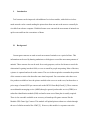
This price can be heavily reduced with the use of a wireless mesh network. A mesh
network relies on communication between multiple nodes in order to transmit data from one
point to the next (see Figure 1). Wireless signals suffer from the inverse square law, which states
that the power will be dissipated over an area in proportion to the inverse square of the distance.
In short, the farther the receiver is from the transmitter, more power is required to transmit a
readable signal. With multiple devices that receive and transmit the signal to the next device the
power required will be lessened. On top of this, the wireless mesh network benefits from a selfhealing property in which the data can still be transmitted even when one device malfunctions.
Figure 1: Wireless Mesh Network [5]
III. Design
In order to prove the use of a mesh network two camera units were required. Each unit
should be able to transmit data to the other unit as well as to the home computer. The units need
to be self-contained and run continuously without human interaction after the start switch is
flipped.
A. Hardware
Just for the sake of a proof of concept prototype, a variant of the ATMEL 8051
microcontroller was used due to availability and past experience. In order to detect motion, a PIR
motion sensor was necessary [8]. The alarm pin on the sensor needs a pull-up resistor with a
value of about 10kΩ. This alarm pin is then raised high until motion occurs within the viewing
angle, at which time it pulses low. The microcontroller needs to see this pulse on an interrupt pin,
for the 8051 port 1 pin 3 was used for the motion interrupt.
For the camera, the LinkSprite JPEG Color Camera [4] was chosen with the optional
infrared LED’s to allow for pictures to be taken in little to no light situations. This allows for the
habits of animals to be recorded day and night as well as to provide little impact on the
environment as far as there is no visible flashing of light. This camera defaults at a baud rate of
38400 bps and will reset to this default. There are also a number of image sizes available to
configure from, but for the sake of speed the fewer bits the better, so the image size was
configured to 160x140.
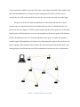
For a wireless module, the XBee Series 2 was used for ease of use, low power consumption,
and relatively long distance when compared to similar solutions such as Bluetooth (see figure 2).
The XBee in combination with the SparkFun XBee Explorer Regulated board allows for easy
serial communication.
Then with the use of the
free program XCTU
provided at digi.com[10],
the XBee modules can be
configured appropriately.
Three of these wireless
modules were necessary,
Figure 2: Bit Rate Standards [9]
one in each unit and one at the
home computer for proof of concept. The module on the home computer needs to be set as the
coordinator of the network by updating the firmware in the XCTU program, while the other
modules in the camera units needs to be set as routers in the network. The destination address for
the routers needs to be set to the coordinator’s MAC address. Then to set up the network each of
the XBee’s need to have the same personal area network (PAN) address which can range
anywhere from hex 0000 to hex FFFF. Finally the baud rate was set to 38400 bps to match the
default from the camera.
Due to these units removing the need for much human interaction a GPS receiver would
prove to be quite useful. With global coordinates tagged on the pictures the user can use geo
tagging to view animal congregational patterns on a map. The Copernicus module was
implemented with these purposes in mind [11]. This GPS receiver uses 3.3V as high, compared
to every other component using 5V, thus a 3.3V volt regulator along with a level converter was
necessary for serial communication. The XSTBY needs a pull-up resistor of about 1kΩ, as well
as having the R2, BOOT, and XRST pins set high in order to set the receiver in run mode. While
in run mode the receiver will periodically transmit GPS location along with the health of the
receiver and other desirable information.
In order for serial communication between the camera, the wireless module, the GPS receiver
and the microcontroller a dual analog 2:4 multiplexer is necessary to avoid transmitting to the
wrong device. In this case there are multiple devices attempting to transmit to the XBee and
there are multiple devices receiving from the 8051 microcontroller. The TxD pin from the
microcontroller needs to be multiplexed to be able to transmit commands to the camera, to send
the camera unit number to the XBee, and to control the mode of the GPS receiver. While the
RxD from the XBee needs to be multiplexed to receive serial data from the camera, from the
microcontroller, and from the GPS receiver. Then the microcontroller uses port 1 pins 4 and 5 as
select pins for the multiplexer.
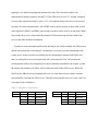
Table 1: Multiplexer Truth Tables
Z
MCU TxD
S2
0
0
1
1
S1
0
1
0
1
Y
Camera RxD
Xbee RxD
GPS RxD
x
Z
Xbee RxD
S2
0
0
1
1
S1
0
1
0
1
Y
Camera TxD
MCU TxD
GPS TxD
x
Table 2: Budget
Component
8051 MCU
JPEG Camera
Xbee S2
Copernicus
GPS antenna
6V battery
PIR sensor
XBee board
XBee dongle
Box
misc
Total
per unit overall
25
50
50
100
23
69
75
150
13
26
10
20
10
20
10
20
25
25
24
48
8
16
273
544
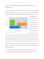
Figure 3: Hardware Schematic
B. Software
The microcontroller needs to be programmed to detect motion as well as to communicate
serially with the other components. Since the camera defaults to a baud rate of 38400 bps for
easy serial communication this baud rate will be used on all applicable components. For the 8051
microcontroller some calculations are necessary in relation to the frequency of the crystal on the
board which in this case is 28.2076 MHz
𝐵𝐵𝐵𝐵𝐵𝐵𝐵𝐵 𝑟𝑟𝑟𝑟𝑟𝑟𝑟𝑟 =
𝑓𝑓𝑐𝑐𝑐𝑐𝑐𝑐𝑐𝑐𝑐𝑐𝑐𝑐𝑐𝑐
[7]
16(0𝑥𝑥𝑥𝑥𝑥𝑥𝑥𝑥𝑥𝑥 − 𝑅𝑅𝑅𝑅𝑅𝑅𝑅𝑅2𝐻𝐻 𝑅𝑅𝑅𝑅𝑅𝑅𝑅𝑅2𝐿𝐿)
where RCAP2H and RCAP2L are the high and low hex values to be set to control the baud rate.
38400 =
28.2076 𝑀𝑀𝑀𝑀𝑀𝑀
=> 𝑋𝑋 ≈ 65490 => 0𝑥𝑥𝑥𝑥𝑥𝑥𝑥𝑥2
16(65536 − 𝑋𝑋)
So RCAP2H and RCAP2L needs to be set to FF and D2 respectively.
For the motion detection port 1 pin 3 was used which corresponds to the CEX0 pin. Thus the
PCA interrupt needs to use module 0 to trigger from a negative edge on CEX0. Inside the
interrupt a motion flag is set high and the interrupt is disabled, to avoid interrupting while in the
middle of capturing an image. The interrupt is re-enabled after the picture process has completed.
After motion is detected the microcontroller sends the camera unit number to the XBee. Then
the command to take a picture is sent to the camera then the microcontroller waits for an
appropriate amount of time for the camera to send the return line. Then the microcontroller sends
the command to see the number of bytes in the JPEG and waits until it receives the return line
with the number of bytes. Next the read JPEG data command is sent with the number of bytes to
be read and the microcontroller waits an appropriate amount of time for all the data and the
return lines to be sent from the camera. Due to an issue of losing the bytes and not enough space
on the board to store them, the camera sends the JPEG data directly to the XBee wireless module
instead of to the 8051. However the 8051 does still need to receive the return line with the
number of bytes in order to send the correct command for all of the bytes to be sent. After the
picture data has been sent from the camera, the microcontroller sends the command to stop the
picture taking process. A delay is added so that the motion sensor does not trip multiple times
within a certain time frame to avoid duplicate pictures. Then the motion flag is reset as well as
the PCA interrupt re-enabled, and the unit is ready to take the next picture.
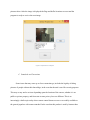
The XBee wireless module will send the data to the next XBee and if the destination address
does not match the MAC address of the current XBee then the process is repeated until the data
is transmitted to the XBee on the home computer. Once the data has made it on to the home
computer, the GUI application needs to have the appropriate COM port open from the XBee.
The GUI reads the received serial data until the end of a read line marked by a “/n” this mark
was added to the unit number sent from the microcontroller. This helps to serve as an indicator
for when the next picture has been captured. In the serial received handler once the “/n” has
occurred a flag is set to begin storing the bytes received. These bytes are then compared to the
beginning of conventional JPEG formatting which states that the beginning of a JPEG starts with
hex number FF followed by hex D8. The location for the start of the JPEG file is saved and a
flag occurs to begin searching for the end of the JPEG marked by hex FF and hex D9. When the
end of the data is located a secondary buffer is created with only the image data. At this time a
file name is created with time stamp and unit number, then the image is created under the file
name, and displayed on the GUI. The filenames are stored in order to navigate through all of the
pictures taken. After the image is displayed the flags and buffer locations are reset and the
program is ready to receive the next image.
Figure 4: Graphical User Interface
C. Standards and Constraints
Some issues that may come up as far as constraints go, includes the legality of taking
pictures of people without their knowledge, in the case that the unit is used for security purposes.
This may or may not be an issue depending upon the location of the camera, whether it is on
public or private property, and from state to state privacy laws are different. This is an
increasingly volatile topic today where remote control drones are now even readily available to
the general populace with camera attached. In the case that this product is used by hunters there
may be issues about tracking animals out of season. Also usage of this unit should allow for
hunter to find trails that are more frequently traveled by animals, which could lead to a spike of
population loss in the area. However hunters have to follow regulations set by the Department of
Natural Resources which should be able to keep game populations from declining rapidly. Trail
cameras are set up outside and in some cases they may become forgotten or lost littering the
environment. To rectify this issue the overall size will be minimized, and with the addition of a
GPS module the unit should not be easily lost.
With the use of a wireless transceiver certain requirements are necessary to consider in
regard to the United States Federal Communications Commission (FCC). The general public
have a degree of wariness around radio waves, and with rising concern for the impacts on health
the FCC chose to implement regulations on these wireless transceivers. Specifically the amount
of power that is allow to be transmitted is not supposed to reach a certain level [6]. Fortunately
the XBee is designed for minimum power output. Another concern with radio frequencies is that
certain bands are to be avoided as these are to be used for national emergencies, or are otherwise
audible to animals and may cause harm. The XBee module is able to cope with this in the US as
well as other countries with different regulations, simply changing a set value will allow the
transceiver to follow these standards.
There are a few standard practices to be wary of in the coding process. First and by far
the most important is to comment, by this it is meant to leave in the margins or besides the code
itself an easily interpreted pseudo-code or even full sentences which describes what the code is
supposed to accomplish. This is particularly important to allow for future debugging, for others
or after a long period of time without looking at the code no one should be expected to remember
exactly what’s going on. Not every line needs to be commented just enough that the general idea
for sections is easily understood should be plenty. Another common practice in coding is to have
all repeatedly used values as a constant variable, this way the code doesn’t seem to use a magical
number that no one else would know where it came from. Another option is to use functions to
determine the number, a good example would be in a loop going through the full length of an
array use a size or length function instead of putting in the number that the array has been set to.
Finally to allow for the code to be easier to read lines should be indented appropriately.
IV. Results
The end product is fully contained with a 5AHr, 6V battery. For demonstration purposes
two units were necessary, one unit within range of the master XBee, and another only within
range of the first unit. When movement is detected
the picture is taken and in a timely manner sent from
one unit to either the other unit or directly stored to
the home computer. The GUI is easily navigated by
an average consumer. Finally, the cost of each unit is
below current prices for similar products.
Figure 5: Final Camera Unit
Appendix A
//Microcontroller Program for Capstone Project
//Nick Jones
//4-16-15
#include <at89c51cc03.h>
#include <stdio.h>
void initialize();
void Command_Camera(char C_buffer[],int l);
void Print_XBee(char C_buffer[], int l);
void GPS_Standby();
void GPS_Run();
void Delay(int n, int l);
void Clear_Buffer();
void Reset();
void Take_Picture();
void Read_JPEG_File_Size();
void File_Content(int XH, int XL);
void Stop_Pictures();
void Compression_Ratio();
void Image_Size();
void Enter_Power_Saving();
void Exit_Power_Saving();
void Change_baud();
xdata unsigned char buffer[100];
xdata char Command_buffer[33];
xdata char XBee_buffer[33];
unsigned int bIndex = 0;
//count of receive interrupts
bit ready = 0;
bit motion =
//transmit flag
0;
int m;
//used for sprintf
void main()
{
unsigned char XL, XH;
initialize();
while(1)
{
if(motion)
//motion detected
{
//Exit_Power_Saving();
Delay(150,285);
m = sprintf(XBee_buffer, "$$$, Cam 2\n");
//unit tag 2
//m = sprintf(XBee_buffer, "$$$, Cam 1\n");
//unit tag 1
Print_XBee(XBee_buffer, m);
Delay(150,285);
Take_Picture();
Delay(150,285);
bIndex=0;
Read_JPEG_File_Size();
while(bIndex < 9);
XH=buffer[7];
XL=buffer[8];
bIndex=0;
//wait for file size
//save file size
Delay(100,285);
File_Content(XH, XL);
Delay(285,285);
Delay(285,285);
Stop_Pictures();
motion = 0;
//
Enter_Power_Saving();
GPS_Run();
Delay(285,285);
motion can be detected again
//delay befor
Delay(285,285);
//GPS_Standby();
EC=1;
//enable pca interrupt
}
}
}
void Receive() interrupt 4 using 1
{
interrupt
//UART
if(TI)
{
ready = 1;
TI=0;
}
if(RI)
{
buffer[bIndex]= SBUF;
bIndex++;
if(bIndex == 100)
{
bIndex =0;
}
RI = 0;
//Clear receive/Transmit
interrupt flag
}
}
void Motion_Detector() interrupt 6 using 2
{
motion = 1;
CCF0 = 0;
EC = 0;
//disable pca interrupt
}
void initialize()
{
P1_4=0;
//Select pin 1
P1_5=0;
//Select pin 2
CKCON = 0x01;
SCON = 0x40;
//(2x mode)
// Enable Transmit
RCLK = 1;
//Turn on reciever clock in T2CON
TCLK = 1;
//Turn on transmit clock in T2CON
RCAP2H = 0xFF;
//38400 baud rate @ 28.2076 Mhz
RCAP2L = 0xD2;
PCON = 0x80;
//Clock / 32 for baud rate
TR2=1;
REN=1;
//receive enable
IEN0=0x90;
EC=1;
CR=1;
CCAPM0 = 0x11;
CCF0 = 0;
//PCA negative edge interrupt enable
TI=0;
RI=0;
//GPS_Standby();
Clear_Buffer();
Delay(155,285);
//Reset();
Image_Size();
Delay(150,285);
//Enter_Power_Saving();
Delay(150,285);
//Change_baud();
//Delay(150,285);
}
void Command_Camera(char C_buffer[], int l)
{
int i;
REN=0;
//transmit enable
P1_4=0;
//MCU -> Camera
P1_5=0;
for(i=0; i<l; i++)
{
ready = 0;
SBUF = C_buffer[i];
while(!ready); //wait for transmit interrupt
}
bIndex = 0;
REN=1;
}
void Print_XBee(char C_buffer[], int l)
{
//receive enable
int i;
REN=0;
//transmit enable
P1_4=1;
//MCU -> XBee
P1_5=0;
for(i=0; i<l; i++)
{
ready = 0;
SBUF = C_buffer[i];
while(!ready); //wait for transmit interrupt
}
bIndex = 0;
REN=1;
//receive enable
}
void GPS_Standby() //force GPS into power saving mode
{
REN=0;
P1_4=0;
//transmit enable
//MCU -> GPS
P1_5=1;
ready = 0;
SBUF = 0xC0;
while(!ready); //wait for transmit interrupt
bIndex = 0;
REN=1;
//receive enable
}
void GPS_Run()
//force GPS out of power saving
{
REN=0;
P1_4=0;
P1_5=1;
ready = 0;
//transmit enable
//MCU -> GPS
SBUF = 0x00;
while(!ready); //wait for transmit interrupt
bIndex = 0;
REN=1;
//receive enable
}
void Clear_Buffer()
{
int i = 0;
for(i=0;i<100;i++)
//Erase buffer
buffer[i] = 0;
}
void Reset()
//Command(HEX): 56 00 26 00
{
//Return (HEX): 76 00 26 00
Command_buffer[0]=0x56;
Command_buffer[1]=0x00;
Command_buffer[2]=0x26;
Command_buffer[3]=0x00;
Command_Camera(Command_buffer, 4);
}
void Take_Picture() //Command(HEX): 56 00 36 01 00
{
00 36 00 00
//Return (HEX): 76
Command_buffer[0]=0x56;
Command_buffer[1]=0x00;
Command_buffer[2]=0x36;
Command_buffer[3]=0x01;
Command_buffer[4]=0x00;
Command_Camera(Command_buffer, 5);
}
void Read_JPEG_File_Size()
//Command(HEX): 56 00 34 01 00
{
//Return (HEX): 76 00 34 00 04 00 00 XH XL
Command_buffer[0]=0x56;
Command_buffer[1]=0x00;
Command_buffer[2]=0x34;
Command_buffer[3]=0x01;
Command_buffer[4]=0x00;
Command_Camera(Command_buffer, 5);
}
void File_Content(int XH, int XL)
00 KH KL XX XX
//Command(HEX): 56 00 32 0C 00 0A 00 00 MH ML 00
{
//Return
(HEX): 76 00 32 00 00 <Interval Time> FF D8 ... <Interval Time> 76 00 32 00 00
Command_buffer[0]=0x56;
Command_buffer[1]=0x00;
Command_buffer[2]=0x32;
Command_buffer[3]=0x0C;
Command_buffer[4]=0x00;
Command_buffer[5]=0x0A;
Command_buffer[6]=0x00;
Command_buffer[7]=0x00;
Command_buffer[8]=0x00;
//MH ML Starting Address
Command_buffer[9]=0x00;
Command_buffer[10]=0x00;
Command_buffer[11]=0x00;
Command_buffer[12]=XH; //0xKH 0xKL Length of JPEG file
Command_buffer[13]=XL;
Command_buffer[14]=0x00; //<interval time> = XX XX*0.01mS (recommended 00 0A)
Command_buffer[15]=0x0A;
Command_Camera(Command_buffer, 16);
}
void Stop_Pictures() //Command(HEX): 56 00 36 01 03
{
(HEX): 76 00 36 00 00
//Return
Command_buffer[0]=0x56;
Command_buffer[1]=0x00;
Command_buffer[2]=0x36;
Command_buffer[3]=0x01;
Command_buffer[4]=0x03;
Command_Camera(Command_buffer, 5);
}
void Compression_Ratio()
0xFF)
//Command(HEX): 56 00 31 05 01 01 12 04 XX (XX: 0x00 to
{
//Return (HEX): 76 00 31 00 00 XX
(XX normally
is 36)
Command_buffer[0]=0x56;
Command_buffer[1]=0x00;
Command_buffer[2]=0x31;
Command_buffer[3]=0x05;
Command_buffer[4]=0x01;
Command_buffer[5]=0x01;
Command_buffer[6]=0x12;
Command_buffer[7]=0x04;
Command_buffer[8]=0x36; //XX
Command_Camera(Command_buffer, 9);
}
void Image_Size()
//Command(HEX): 56 00 31 05 04 01 00 19 XX (XX=11 for (320*240);
00 for(640*480); 22 for (160*120))
{
00 31 00 00
Command_buffer[0]=0x56;
Command_buffer[1]=0x00;
//Return (HEX): 76
Command_buffer[2]=0x31;
Command_buffer[3]=0x05;
Command_buffer[4]=0x04;
Command_buffer[5]=0x01;
Command_buffer[6]=0x00;
Command_buffer[7]=0x19;
Command_buffer[8]=0x22; //XX
Command_Camera(Command_buffer, 9);
Delay(150,285);
Reset();
}
void Enter_Power_Saving() //Command(HEX): 56 00 3E 03 00 01 01
{
//Return (HEX): 76 00 3E 00 00
Command_buffer[0]=0x56;
Command_buffer[1]=0x00;
Command_buffer[2]=0x3E;
Command_buffer[3]=0x03;
Command_buffer[4]=0x00;
Command_buffer[5]=0x01;
Command_buffer[6]=0x01;
Command_Camera(Command_buffer, 7);
}
void Exit_Power_Saving()
//Command(HEX): 56 00 3E 03 00 01 00
{
//Return (HEX): 76 00 3E 00 00
Command_buffer[0]=0x56;
Command_buffer[1]=0x00;
Command_buffer[2]=0x3E;
Command_buffer[3]=0x03;
Command_buffer[4]=0x00;
Command_buffer[5]=0x01;
Command_buffer[6]=0x01;
Command_Camera(Command_buffer, 7);
}
void Change_baud()
9600; 0D A6 for 115200)
//Command(HEX): 56 00 24 03 01 XX XX (XX XX = AE C8 for
{
(HEX): 76 00 24 00 00
//Return
Command_buffer[0]=0x56;
Command_buffer[1]=0x00;
Command_buffer[2]=0x24;
Command_buffer[3]=0x03;
Command_buffer[4]=0x01;
Command_buffer[5]=0x0D; //XX
Command_buffer[6]=0xA6; //XX
Command_Camera(Command_buffer, 7);
RCAP2H = 0xFF;
//19200 baud rate @ 28.2076 Mhz
RCAP2L = 0xF0;
}
void Delay(int n, int l)// ~2 microsecond paramter driven delay
{
int i,j,k;
for(k=0; k<n; k++)
{
for(i=0; i<l; i++)
{
for(j=0; j<15; j++);
}
}
}
//GUI for Capstone Project
//Nick Jones
//4-16-15
using System;
using System.Collections.Generic;
using System.ComponentModel;
using System.Data;
using System.Drawing;
using System.Linq;
using System.Text;
using System.Threading.Tasks;
using System.Windows.Forms;
using System.IO.Ports;
using System.IO;
namespace Senior_Project_GUI
{
public partial class Form1 : Form
{
byte[] buffer = new byte[50000];
int c = 0;
int i=0;
int Number_pic = 0;
string[] split_It;
string[] Saved_Files = new string [50000];
delegate void SetTextCallback(String text);
public Form1()
{
InitializeComponent();
}
private void Form1_Load(object sender, EventArgs e)
{
}
private void button1_Click(object sender, EventArgs e) //opens serial port and initializes
image
{//run
listBox1.Items.Insert(0, "Initial ");
//mySerialPort.BaudRate = 115200;
mySerialPort.Open();
pictureBox1.Image = System.Drawing.Image.FromFile("download.jpg");
}
private BinaryWriter writer;
bool Read_Raw = false;
//data flag
int Data_Index = 0;
int Data_End = 0;
DateTime saveNow = DateTime.Now; //time stamp
private void mySerialPort_DataReceived(object sender, SerialDataReceivedEventArgs e)
{
if (!Read_Raw)
{
string Input = mySerialPort.ReadLine();
split_It = Input.Split(',');
if (split_It[0] == "$$$")
{
InsertText(split_It[1]); //display the unit number
Read_Raw = true;
}
}
else
{
while (mySerialPort.BytesToRead > 0)
{
buffer[c] = (byte)mySerialPort.ReadByte();
if(c>5)
{
if (buffer[c - 6] == 0x76)
{
if (buffer[c - 5] == 0x00)
{
if (buffer[c - 4] == 0x32)
{
if (buffer[c - 3] == 0x00)
{
if (buffer[c - 2] == 0x00)
{
if (buffer[c - 1] == 0xFF)
{
if (buffer[c] == 0xD8)
{
Data_Index = c-1;
//look for start of JPEG
InsertText("Data_Start = "+Data_Index );
}
}
}
}
}
}
}
if (buffer[c - 6] == 0xFF)
{
if (buffer[c - 5] == 0xD9)
{
if (buffer[c - 4] == 0x76)
{
if (buffer[c - 3] == 0x00)
{
if (buffer[c - 2] == 0x32)
{
if (buffer[c - 1] == 0x00)
{
if (buffer[c] == 0x00)
{
//look for end of JPEG
Data_End = c - 5;
InsertText("Data_End = " + Data_End);
byte[] buffer2 = new byte[Data_End - Data_Index];
for (int n = Data_Index; n < Data_End; n++)
{
buffer2[n - Data_Index] = buffer[n];
}
saveNow = DateTime.Now;
string file_name = String.Concat(split_It[1], " ", saveNow,
".jpeg");
file_name = file_name.Trim();
file_name = file_name.Replace(':', ';');
file_name = file_name.Replace('/', '-');
//change time stamp
to appropriate file name
using (FileStream stream = new FileStream(file_name,
FileMode.Append))
{
using (writer = new BinaryWriter(stream))
{
writer.Write(buffer2);
}
}
i = Number_pic;
Saved_Files[i] = file_name;
Number_pic++;
pictureBox1.Image =
System.Drawing.Image.FromFile(file_name);
//store filename
c = -1;
InsertText("Pictures Captured = " + Number_pic);
Read_Raw = false;
//reset for next picture
Data_Index = 0;
Data_End = 0;
}
}
}
}
}
}
}
}
c++;
}
}
}
private void InsertText(string text)
{
// InvokeRequired required compares the thread ID of the
// calling thread to the thread ID of the creating thread.
// If these threads are different, it returns true.
if (this.listBox1.InvokeRequired)
{
SetTextCallback d = new SetTextCallback(InsertText);
this.Invoke(d, new object[] { text });
}
else
{
this.listBox1.Items.Insert(0, text);
}
}
private void button1_Click_1(object sender, EventArgs e)
{//previous
i--;
if (i < 0)
{
i = 0;
pictureBox1.Image = System.Drawing.Image.FromFile(Saved_Files[i]);
}
else
{
pictureBox1.Image = System.Drawing.Image.FromFile(Saved_Files[i]);
}
}
private void pictureBox1_Click(object sender, EventArgs e)
{
}
private void button2_Click(object sender, EventArgs e)
{
//next
i++;
if(i < Number_pic)
{
pictureBox1.Image = System.Drawing.Image.FromFile(Saved_Files[i]);
}
else
{
i = Number_pic-1;
pictureBox1.Image = System.Drawing.Image.FromFile(Saved_Files[i]);
}
}
}
}
References
[1] (n,d). HCO BG30L Mobile (GSM) Surveillance Camera/Alarm System User’s Manual.
[Online].
Available: http://www.hcooutdoors.com/media/wysiwyg/findme/hco_bg30l_manual.pdf
[2] (n.d.). GPS Game Spy Connect. [Online]. Available:http://www.moultriefeeders.com/gpsgame-spy-connect-pay-as-you-go
[3] (2009). XBee®/XBee-PRO® RF Modules. [Online].
Available: https://www.sparkfun.com/datasheets/Wireless/Zigbee/XBee-Datasheet.pdf
[4] (2010, Nov). LinkSprite JPEG Color Camera Serial UART Interface With Infrared.
[Online]. Available: http://www.linksprite.com/upload/file/1291522825.pdf
[5] (n.d). 5.4.12 Mesh Networking. [Online]. Available: http://esdocs.org/docs/index36250.html?page=5
[6] (n.d.) Radio Frequency Safety. [Online]. Available: http://www.fcc.gov/encyclopedia/radiofrequency-safety
[7] (n.d.) AT89C51CC03. [Online]. Available: http://www.atmel.com/images/doc4182.pdf
[8] (n.d.) PIR Sensor Module Memo. [Online].
Available: https://www.sparkfun.com/datasheets/Sensors/Proximity/SE-10.pdf
[9] (n.d) Low-Power 2.4GHz ISM Transceiver for Consumer Applications. [Online].
Available: http://www.atmel.com/microsite/at86rf232/default.aspx
[10] (n.d) XCTU Next generation configuration platform for XBee. [Online].
Available: http://www.digi.com/products/wireless-wired-embedded-solutions/zigbee-rfmodules/xctu
[11] (July, 2006) Copernicus™ GPS Receiver Reference Manual. [Online].
Available: https://www.sparkfun.com/datasheets/GPS/Copernicus_Manual.pdf