1
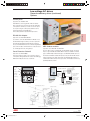
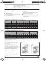
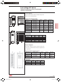
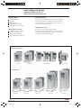
Low voltage AC drives
General machinery drives
Main features and dimensions
Unique features
Mounting options
Fast and extensive I/O
In addition to the conventional wall mounting and time-saving DIN
PID control
rail mounting, ACS140 also offers flange-mounting. The heatsink
Application macros
is located outside the enclosure and hence the major share of the
Many installation possibilities
power loss is external to the enclosure.
200 to 480 V, 1-phase or 3-phase
Heatsinkless series
More value for money
In cases where space is a limitation, drives without
Possibility to have IP 21 enclosure
a heatsink can be delivered as standard. The user has to provide
Very fast and accurate control
an installation surface with sufficient cooling. For more information,
Extremely good repeatability
please refer to the ACS140 User’s Manual.
Cost optimization without the panel
Mounting options
mounting on DIN rail
wall mounting
heatsinkless
flange mounting
149 mm
119 mm
80 mm
frame size H
3/54
80 mm
frame size A
245 mm
146 mm
146 mm
146 mm
218 mm
Dimensions
186 mm
80 mm
frame size B
169 mm
80 mm
frame size C
176 mm
80 mm
frame size D
ABB
1SDC007200C0201
0302_LVACdrives.indd 54
7-02-2005 17:04:52
Low voltage AC drives
General machinery drives
Ratings, types and voltages
1-phase supply with heatsink
Nominal
motor
Nominal ratings
Input
Output
current
current
Frame
size/
weight
Max.
output
current
Overcurrent
(peak)
Overtemp.
(heatsink)
Line
fuse1)
Power losses
Power
Control
circuit
circuit
P N 2)
kW
kg
I 1N
A
I 2N
A
A
A
oC
A
W
ACS141-K18-1
0.12
A/0.9
2.7
1.0
1.5
3.2
90
6
7
8
ACS141-K25-1
0.18
A/0.9
4.4
1.4
2.1
4.5
90
6
10
10
ACS141-K37-1
0.25
A/0.9
5.4
1.7
2.6
5.5
90
10
12
12
ACS141-K75-1
0.37
A/0.9
6.9
2.2
3.3
7.1
90
10
13
14
ACS141-1K1-1
0.55
A/0.9
9.0
3.0
4.5
9.7
90
10
19
16
ACS141-1K6-1
0.75
B/1.2
10.8
4.3
6.5
13.8
90
16
27
17
ACS141-2K1-1
1.1
C/1.6
14.8
5.9
8.9
19.0
95
16
39
18
ACS141-2K7-1
1.5
C/1.6
18.2
7.0
10.5
23.5
95
20
48
19
ACS141-4K1-1
2.2
D/1.9
22.0
9.0
13.5
34.5
95
25
70
20
Max.
output
current
Overcurrent
(peak)
Overtemp.
(heatsink)
Line
fuse1)
W
LV AC drives
Type/order code
1-phase supply heatsinkless
Type/order code
Nominal
motor
Frame
size/
weight
Nominal ratings
Input
Output
current
current
Power losses
Power
Control
circuit
circuit
P N 2)
kW
kg
I 1N
A
I 2N
A
A
A
oC
A
W
ACS141-H18-1
0.12
H/0.8
2.7
1.0
1.5
3.2
90
6
7
8
ACS141-H25-1
0.18
H/0.8
4.4
1.4
2.1
4.5
90
6
10
10
ACS141-H37-1
0.25
H/0.8
5.4
1.7
2.6
5.5
90
10
12
12
ACS141-H75-1
0.37
H/0.8
6.9
2.2
3.3
7.1
90
10
13
14
ACS141-1H1-1
0.55
H/0.8
9.0
3.0
4.5
9.7
90
10
19
16
ACS141-1H6-1
0.75
H/0.8
10.8
4.3
6.5
13.8
90
16
27
17
Overcurrent
(peak)
Overtemp.
(heatsink)
Line
fuse1)
W
3-phase supply with heatsink
Type/order code
Nominal
motor
Frame
size/
weight
Nominal ratings
Input
Output
current
current
Max.
output
current
Power losses
Power
Control
circuit
circuit
P N 2)
kW
kg
I 1N
A
I 2N
A
A
A
oC
A
W
W
ACS143-K75-1
0.37
A/0.8
3.2
2.2
3.3
7.1
90
6
13
14
ACS143-1K1-1
0.55
A/0.8
4.2
3.0
4.5
9.7
90
6
19
16
ACS143-1K6-1
0.75
B/1.1
5.3
4.3
6.5
13.8
90
6
27
17
ACS143-2K1-1
1.1
C/1.5
7.2
5.9
8.9
19.0
90
10
39
18
ACS143-2K7-1
1.5
C/1.5
8.9
7.0
10.5
23.5
95
10
48
19
ACS143-4K1-1
2.2
D/1.8
12.0
9.0
13.5
34.5
95
16
70
20
Max.
output
current
Overcurrent
(peak)
Overtemp.
(heatsink)
Line
fuse1)
3-phase supply with heatsink
Type/order code
Nominal
motor
Frame
size/
weight
Nominal ratings
Input
Output
current
current
Power losses
Power
Control
circuit
circuit
P N 2)
kW
kg
I 1N
A
I 2N
A
A
A
oC
A
W
W
ACS143-K75-3
0.37
A/0.8
2.0
1.2
1.8
4.2
90
6
14
14
ACS143-1K1-3
0.55
A/0.8
2.8
1.7
2.6
5.6
90
6
20
16
ACS143-1K6-3
0.75
B/1.1
3.6
2.0
3.0
6.6
90
6
27
17
ACS143-2K1-3
1.1
C/1.1
4.8
2.8
4.2
9.2
90
6
39
18
ACS143-2K7-3
1.5
C/1.5
5.8
3.6
5.4
11.9
95
10
48
19
ACS143-4K1-3
2.2
D/1.8
7.9
4.9
7.4
16.3
95
10
70
20
Max.
output
current
Overcurrent
(peak)
Overtemp.
(heatsink)
Line
fuse1)
3-phase supply heatsinkless
1)
2)
Frame
size/
weight
Nominal ratings
Input
Output
current
current
Power losses
Power
Control
circuit
circuit
Type/order code
Nominal
motor
kg
H/0.8
I 1N
A
2.0
I 2N
A
1.2
A
1.8
A
4.2
oC
ACS143-H75-3
P N 2)
kW
0.37
90
A
6
W
14
W
14
ACS143-1H1-3
0.55
H/0.8
2.8
1.7
2.6
5.6
90
6
20
16
ACS143-1H6-3
0.75
H/0.8
3.6
2.0
3.0
6.6
90
6
27
17
ACS143-2H1-3
1.1
H/0.8
4.8
2.8
4.2
9.2
90
6
39
18
Fuse type: UL class CC or T. For non-UL installations IEC269 gG.
PN rated motor power. The power ratings in kW apply to most 2- and 4-pole IEC 34 motors. The current ratings are the
same regardless of supply voltages. The rated current of the ACS100 drive must be higher than or equal to the rated
motor current to achieve the rated motor power given in the table.
ABB
3/55
1SDC007200C0201
0302_LVACdrives.indd 55
7-02-2005 17:04:54
Low voltage AC drives
General machinery drives (continued)
Technical specification
Mains connection
Protection limits
Power range
0.12 to 2.2 kW
Overvoltage, 200 to 240 V units
Voltage
1-phase and 3-phase, 200 to 240 V, ±10%
Running V DC
420 (corr. to 295 V input)
3-phase, 380 to 480 V, ±10%
Start inhibit V DC
390 (corr. to 276 V input)
Frequency
48 to 63 Hz
Overvoltage, 380 to 480 V units
Power Factor
0.98
Running V DC
Use 60°C rated power cable (75°C if Tamb above 45°C).
Start inhibit V DC
Max. wire sizes (mm2)
842 (corr. to 595 V input)
661 (corr. to 380 - 415 V input)
765 (corr. to 440 - 480 V input)
4 single core/torque 0.8 Nm
Undervoltage, 200 to 240 V units
Motor connection
Voltage
3-phase, from 0 to USUPPLY
Frequency
0 to 300 Hz
Continuous loading
Running V DC
200 (corr. to 142 V input)
Start inhibit V DC
230 (corr. to 162 V input)
Undervoltage, 380 to 480 V units
Running V DC
Start inhibit V DC
capability (constant
333 (corr. to 247 V input)
436 (corr. to 380 - 415 V input)
505 (corr. to 440 - 480 V input)
torque at a max. ambient
temperature of 40°C)
Rated output current I2N
Overload capacity
At constant torque 1.5 x I2N, for 1 minute every 10 minutes
(at a max. ambientat
At constant torque 1.25 x I2N, for 2 minutes every 10 minutes
temp. of 40°C)
Environmental limits
Ambient temperatures
Output current = I2, fswitch = 4 kHz: 0 to 40°C
Output current = 0.8 · I2, fswitch = 4 kHz: 40 to 50°C
Characteristic data for short-time, intermittent and
periodic load cycles are available on request.
Output current = I2, fswitch = 8 kHz: 0 to 30°C
Switching frequency
Standard 4 kHz, Low-noise 8 kHz, Silent 16 kHz
Output current = 0.9 · I2, fswitch = 8 kHz: 30 to 40°C
Acceleration time
0.1 to 1800 s
Deceleration time
0.1 to 1800 s
Output current = 0.75 · I2, fswitch = 16 kHz: 0 to 30°C
Altitude
Output current = I2: 0 to 1000 m
Output current reduced by 1% per 100 m
For max. motor cable lengths see „Options/Input and Output Chokes“
over 1000 m to 2000 m
Relative humidity
Programmable control connections
Max. wire sizes (mm2)
0.5-1.5 (AWG 22...AWG 16)/torque 0.4 Nm
Two analog inputs:
Voltage signal
0 (2) to 10 V, 200 kΩ single-ended
Current signal
0 (4) to 20 mA, 500 Ω single-ended
lower than 95%
(without condensation)
Protection class
IP 20
Paint colour
NCS 1502-Y, RAL 9002, PMS 420 C
Contamination levels
no conductive dust, corrosive liquids
or gases (IEC 721-3-3).
Potentiometer
reference value
10 V ±2% max. 10 mA, 1 kΩ ≤ R ≤ 10 kΩ
Response time
≤ 60 ms
Resolution
0.1%
Accuracy:
±1%
One analog output
0 (4) to 20 mA, load <500 Ω
Auxiliary voltage
12 V DC, max. 100 mA
Five digital inputs
12 V ... 24 V DC with internal or external supply,
PNP and NPN
Product compliance
Low Voltage Directive 73/23/EEC with supplements
EMC Directive 89/336/EEC with supplements
Quality assurance system ISO 9001 and ISO 14001
CE, UL, ULc and C-Tick approvals
Options
Input impedance
1.5 kΩ
Control panel
Response time
≤ 9 ms
Extension cable 3 m with IP 65 Kit for control panels PEC-98-0008
Two relay outputs
Switching voltage
RS 485/232 adapter
12 to 250 V AC or max 30 V DC/0.5 A
Maximum continuous
current
EMC IP 20 input filters
10 mA to 2 A
Serial communication
3/56
Brake units and choppers
Fieldbus modules
for control panel or
external control
DriveWindow Light 2
Input and output chokes
Modbus protocol
NEMA 1/ IP 21 Installation kits
ABB
1SDC007200C0201
0302_LVACdrives.indd 56
7-02-2005 17:04:55
Low voltage AC drives
General machinery drives (continued)
Options
Control panel
Type/order code: ACS100 - PAN
ACS140 drives can be bought with or without a detachable control panel. If you prefer to buy the drive without the
control panel we still offer you a chance to have the panel
as an option. Using the control panel, parameters can be
exchanged between two ACS140 drives.
LV AC drives
This is called parameter upload/download procedure.
RS 485/232 Adapter
Type/order code: ACS140 RS 485/232
If you want to control the ACS140 drive via Modbus or use
the DriveWindow Light 2 software you need to replace the
panel with the RS 485/232 adapter. When the adapter is
used, several ACS140 units can be controlled using Modbus
protocol. The modbus communication also creates the base
ABC fieldbus modules
for controlling the drive via other gateways.
Type/order codes: ABC-PDP and ABC-DEV
Up to ten drives can be controlled with one ABC fieldbus module. The drives
Panel Extension Cable Kit
may be of type ACS140 and ACS160. ABC modules are available for Profibus
Type/order code: PEC-98-0008
(type code ABC-PDP) and DeviceNet (type code ABC-DEV) fieldbus protocols.
This option includes a gasket, a 3 m connection cable for
The module is DIN rail mountable with protection class IP 20. The ABC module
control panels, fixing material for the cables and a drilling jig.
requires 24 V DC power supply and provides an RS 485 Modbus interface for
With this kit IP 65 protection class is achieved.
communication with the drives. The response time on the Modbus network is approximately 200 ms per drive.
control
modes
RS 485 terminal X2
fault
indicator
units
display
modes
shaft
direction
start/stop
menu
RS 485 bus
termination
jumpers S2
and S3
3 (A)
2 (C)
1 (B)
3 (A)
2 (C)
direction
enter
1 (B)
ACS140 with
RS 485/232
adapter
up/down
LEDs:
RxD
TxD
power
RS 232/RS 485
mode select
jumper S5
communication
speed setting
DIP-switch S1
RS 232
terminal X4
RS 485 terminal X3
mounting plate or door
clamp for cable
mounting screws
with sleeve
gasket
cable hole
control panel
plastic clamp with tape
ABB
3/57
1SDC007200C0201
0302_LVACdrives.indd 57
7-02-2005 17:04:55
Low voltage AC drives
General machinery drives (continued)
Options (continued)
EMC Filters
Instructions to comply with EN61800-3:
To comply with:
To comply with:
2nd Environment, unrestricted distribution, always use optional
1st Environment, unrestricted distribution, please contact your
RFI filter as specified in the table below
ABB drives channerl partner.
2nd Environment, restricted distribution, always use optional
1st Environment, restricted distribution, always use optional RFI
RFI filter as specified in the table below. If RFI filters are to be
filter as specified in the table below.
avoided, an EMC plan has to be created between the customer
and the sales person.
1-phase supply voltage 200 to 240 V, 0.12 to 2.2 kW
Type/order code
Filter type
Max. motor cable length m
Switching frequency
4 kHz
1st environment
8 kHz
16 kHz
Dimensions
2nd environment
4 kHz
8 kHz
16 kHz
A
mm
B
mm
C
mm
D
mm
ACS141-K18-1, -H18-1
ACS100/140-IFAB-1
30
20
10
50
50
10
81
186
191
42
ACS141-K25-1, -H25-1
ACS100/140-IFAB-1
30
20
10
50
50
10
81
186
191
42
ACS141-K37-1, -H37-1
ACS100/140-IFAB-1
30
20
10
50
50
10
81
186
191
42
ACS141-K75-1, -H75-1
ACS100/140-IFAB-1
30
20
10
75
75
10
81
186
191
42
ACS141-1K1-1, -1H1-1
ACS100/140-IFAB-1
30
20
10
75
75
10
81
186
191
42
ACS141-1K6-1, -1H6-1
ACS100/140-IFAB-1
30
20
10
75
75
10
81
186
228
42
ACS141-2K1-1
ACS100/140-IFCD-1
30
20
10
75
75
10
81
286
211
42
ACS141-2K7-1
ACS100/140-IFCD-1
30
20
10
75
75
10
81
286
211
42
ACS141-4K1-1
ACS100/140-IFCD-1
30
20
10
75
75
10
81
286
218
42
3-phase supply voltage 380 to 480 V, 0.37 to 2.2 kW
Type/order code
Filter type
Max. motor cable length m
Switching frequency
4 kHz
1st environment
8 kHz
16 kHz
Dimensions
2nd environment
4 kHz
8 kHz
16 kHz
A
mm
B
mm
C
mm
D
mm
ACS143-K75-3, -H75-3
ACS140-IFAB-3
30
20
10
30
30
10
81
186
191
42
ACS143-1K1-3, -1H1-3
ACS140-IFAB-3
30
20
10
50
50
10
81
186
191
42
ACS143-1K6-3, -1H6-3
ACS140-IFAB-3
30
20
10
50
50
10
81
186
228
42
ACS143-2K1-3, -2H1-3
ACS140-IFAB-3
30
20
10
50
50
10
81
286
211
42
ACS143-2K7-3
ACS140-IFCD-3
30
20
10
50
50
10
81
286
211
42
ACS143-4K1-3
ACS140-IFCD-3
30
20
10
50
50
10
81
286
218
42
RFI filter type code ACS100 -FLT-C allows you to use longer motor cables.
Please contact your ABB drives channel partner. IFAB, IFCD and FLT-C filters with protection class IP 20.
Note! With types ACS...H mount the filter next to the drive.
3-phase supply voltage 200 to 240 V,
0.37 to 2.2 kW
Use EMC filter type ACS140-FLT-C with all
ACS103-xKx-1 converter types. Maximum motor cable
length is 100 m in 1st Environment, restricted distribution with
4 kHz and 8 kHz switching frequency. For ACS103-4K1-1
with EMC filter the maximum continuous load is 70% of
nominal.
NEMA 1/ IP 21 Installation Kit
Type/order code: NEMA 1/ IP 21
With this installation kit NEMA 1/ IP 21 protection class is
achieved for ACS140 and for the EMC filter, if the filter is
attached directly to the drive.
3/58
ABB
1SDC007200C0201
0302_LVACdrives.indd 58
7-02-2005 17:04:57
Low voltage AC drives
General machinery drives (continued)
Options (continued)
Brake Options
Compact-sized brake units which include brake chopper and
resistor, can be used with ACS140.
Brake units technical data
Frequency converter
Resistor
Continuous
Max. output
input voltage
OHM
output W
20 s W
ACS-BRK-A
200 – 240 V AC
400
150
350
380 – 480 V AC
ACS-BRK-B
1000
200 – 240 V AC
150
400
32
2000
1000
380 – 480 V AC
ACS-BRK-C
2400
200 – 240 V AC
4500
380 – 480 V AC
ACS-BRK-D
12000
200 – 240 V AC
10.5
7000
14000
4
5000
30000
50
400
2400
380 – 480 V AC
ACS-BRK-E
LV AC drives
Brake unit
type/order code
42000
200 – 240 V AC
–
ACS-BRK-F
200 – 240 V AC
–
Dimensions
Brake unit
type/order code
Width
mm
Height
mm
Depth
mm
Weight
kg
ACS-BRK-A
90
ACS-BRK-B
90
240
180
1.2
300
285
ACS-BRK-C
1.5
150
500
347
7.5
ACS-BRK-D
270
600
450
20.5
ACS-BRK-E
270
600
450
18.5
ACS-BRK-F
90
300
285
1.5
Brake Choppers
With a brake chopper the customer selects the resistor used.
This ensures an optimum match between the equipment and
the requirements.
Brake choppers technical data
Brake chopper
type/order code
ACS-BRK-BL
Fequency converter
Resistance
Continuous
Max. output
input voltage
OHM
output W
20 s W
200 - 240 V AC
150
400
1000
32
2000
4500
380 - 480 V AC
ACS-BRK-CL
200 - 240 V AC
2400
380 - 480 V AC
12000
Dimensions
Brake chopper
type/order code
ABB
Width
Height
Depth
mm
mm
mm
ACS-BRK-BL
93
250
75
ACS-BRK-CL
125
360
106.5
3/59
1SDC007200C0201
0302_LVACdrives.indd 59
7-02-2005 17:04:58