1
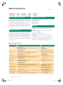
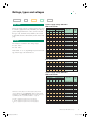
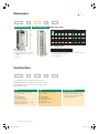
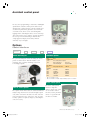
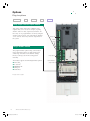
ABB standard drives ACS550, 0.75 to 355 kW Technical catalogue BUSINESS PROFILE INDUSTRIES PRODUCTS APPLICATIONS EXPERTISE PARTNERS SERVICES ACS550_EN_revG.indd 1 25.5.2005 14:33:02 Two ways to select your drive Choice 1: Simply contact your local ABB drives sales office (see page 15) and let them know what you want. Use page 3 as a reference section for more information. Type code: 1 2 3 4 5 ACS550 - Choice 2: Build up your own ordering code using the simple 7-step approach below. Each step is accompanied by a reference to a page that is filled with useful information. 01 - 03A3 - 4 + B055 Product series Rating and types Voltages Dimensions Construction 6 Options 7 2 OR External options 3AFE 64792857 REV G EN 25.5.2005 ACS550_EN_revG.indd 2 25.5.2005 14:33:34 Contents ABB standard drives, ACS550 Page ABB standard drives .................................................................................................................................4 Ratings, types and voltages .....................................................................................................................5 Dimensions ................................................................................................................................................6 Construction ..............................................................................................................................................6 1 2 3 4 5 Assistant control panel .............................................................................................................................7 Options ......................................................................................................................................................7 Control interfaces How to select options........................................................................................................................7 Basic control panel ............................................................................................................................7 Plug-in options Extended relay output option module ................................................................................................8 Plug-in fieldbus module .....................................................................................................................8 External options DriveWindow Light 2 .........................................................................................................................9 Output chokes ..................................................................................................................................9 Brake units and choppers ...............................................................................................................10 6 7 Technical data..........................................................................................................................................10 Cooling............................................................................................................................................10 Fuse connections ............................................................................................................................11 Technical specification ............................................................................................................................12 Control connections ................................................................................................................................13 Service products .....................................................................................................................................14 Contact and web information .................................................................................................................15 3AFE 64792857 REV G EN 25.5.2005 ACS550_EN_revG.indd 3 3 25.5.2005 14:33:34 ABB standard drives ACS550 - 01 - 03A3 - 4 What is an ABB standard drive? The ABB standard drive is simple to buy, install, configure and use, saving considerable time. It is widely available through ABB’s distributors, hence the use of the term standard. The drive has common user and process interface with fieldbus, common software tools for sizing, commissioning, maintenance and common spare parts. Where can it be used? The ABB standard drive can be used in a wide range of industries. Typical applications include pump, fan and constant torque use, such as conveyors. The ABB standard drive is ideal in those situations where there is a need for simplicity to install, commission and use and where customizing or special product engineering is not required. + B055 ABB standard drive promises Precise delivery Quick installation Rapid start-up Trouble-free use Highlights Assistant control panel providing intuitive use of the drive Patent pending swinging choke for superior harmonic reduction Sensorless vector control Integral RFI filter for 1st and 2nd environment as standard Flexible fieldbus system with built-in Modbus and numerous internally mountable fieldbus adapters UL, cUL, CE, C-Tick and GOST R approved What are its main features? Feature Note Benefit Two soft-keys, function of which changes according to the state of the panel Built-in “Help” button Real-time clock, allows timed tracing of faults and setting of parameters to activate at various times of day Changed parameters menu Easy commissioning Fast set-up Easier configuration Rapid fault diagnosis Quick access to recent parameter changes Brake chopper Built-in up to 11 kW Reduced cost Chokes Swinging chokes - matches the right inductance to the right load, thereby suppressing and reducing harmonics Reduces Total Harmonic Distortion (THD) emissions up to 25% Connectivity Simple to install: Easy connection of cables Easy connection to external fieldbus systems through multiple I/Os and plug-in options Reduced installation time Secure cable connections Diagnostic assistant Activated when fault occurs Quick fault diagnostics EMC 1st and 2nd environment RFI filters as standard No need for additional external filtering Fieldbus Built-in Modbus using RS 485 Optional plug-in fieldbus modules Reduced cost Intuitive features Noise optimisation: Increases switching frequency of drive when drive temperature is reduced Controlled cooling fan: the drive is cooled only when necessary Assistant control panel 4 Considerable motor noise reduction Reduces inverter noise and improves energy efficiency Maintenance assistant Monitors running hours or motor rotation Takes care of preventative maintenance of drive, the motor or run application Mounting template Supplied separately with unit Quick and easy to mark mounting screw holes on installation surface Sensorless vector control Improved motor control performance Enables wider range of applications Start-up assistant Easy set-up of parameters Guides user through all essential settings without going to parameter list 3AFE 64792857 REV G EN 25.5.2005 ACS550_EN_revG.indd 4 25.5.2005 14:33:34 Ratings, types and voltages ACS550 - 01 - 03A3 - 4 Type code This is the unique reference number (shown above and in column 7, right) that clearly indentifies your drive by power rating and frame size. Once you have selected the type code, the frame size (column 8) can be used to determine the drives dimensions, shown on the next page. Voltages The ACS550 is available in two voltage ranges: 4 = 380 - 480 V 2 = 208 - 240 V Insert either “4” or “2”, depending on your chosen voltage, into the type code shown above. + B055 3-phase supply voltage 380-480 V Wall mounted units Normal use Ratings Heavy-duty use Type code Frame size 2.4 3.3 4.1 5.4 6.9 8.8 11.9 15.4 23 31 38 44 59 77 96 124 156 162 ACS550-01-03A3-4 ACS550-01-04A1-4 ACS550-01-05A4-4 ACS550-01-06A9-4 ACS550-01-08A8-4 ACS550-01-012A-4 ACS550-01-015A-4 ACS550-01-023A-4 ACS550-01-031A-4 ACS550-01-038A-4 ACS550-01-044A-4 ACS550-01-059A-4 ACS550-01-072A-4 ACS550-01-096A-4 ACS550-01-124A-4 ACS550-01-157A-4 ACS550-01-180A-4 ACS550-01-195A-4 R1 R1 R1 R1 R1 R1 R2 R2 R3 R3 R4 R4 R4 R5 R6 R6 R6 R6 192 224 302 414 477 515 590 ACS550-02-245A-4 ACS550-02-289A-4 ACS550-02-368A-4 ACS550-02-486A-4 ACS550-02-526A-4 ACS550-02-602A-4 ACS550-02-645A-4 R7 R7 R8 R8 R8 R8 R8 PN kW PN hp I2N A Phd kW Phd hp I2hd A 1.1 1.5 2.2 3 4 5.5 7.5 11 15 18.5 22 30 37 45 55 75 90 110 1.5 2 3 3 5 7.5 10 15 20 25 30 40 50 75 100 125 150 150 3.3 4.1 5.4 6.9 8.8 11.9 15.4 23 31 38 44 59 72 96 124 157 180 195 0.75 1.1 1.5 2.2 3 4 5.5 7.5 11 15 18.5 22 30 37 45 55 75 90 1 1.5 2 3 3 5 7.5 10 15 20 25 30 40 60 75 100 125 125 150 200 250 350 400 450 500 Free standing units 132 160 200 250 280 315 355 200 200 300 400 450 500 500 245 289 368 486 526 602 645 110 132 160 200 250 280 315 3-phase supply voltage 208-240 V Wall mounted units Ratings Normal use Heavy-duty use PN I2N Phd Phd I2hd PN kW hp A kW hp A Normal use vs heavy-duty use. For the majority of pump, fan and conveyor applications, select “Normal use” figures. For high overload requirements, select “Heavy-duty use” figures. If in doubt contact your local ABB sales office or your drives distributor - see page 15. PN for kW = Typical motor power in 400 V at normal use PN for hp = Typical motor power in 460 V at normal use Phd for kW = Typical motor power in 400 V at heavy-duty use Phd for hp = Typical motor power in 460 V at heavy-duty use 0.75 1.1 1.5 2.2 4.0 5.5 7.5 11.0 15.0 18.5 22.0 30.0 37.0 45.0 55.0 75.0 1.0 1.5 2.0 3.0 5.0 7.5 10.0 15.0 20.0 25.0 30.0 40.0 50.0 60.0 75.0 100 4.6 6.6 7.5 11.8 16.7 24.2 30.8 46.2 59.4 74.8 88.0 114 143 178 221 248 0.75 0.75 1.1 1.5 3.0 4.0 5.5 7.5 11.0 15.0 18.5 22.0 30.0 37.0 45.0 55.0 0.8 1.0 1.5 2.0 3.0 5.0 7.5 10.0 15.0 20.0 25.0 30.0 40 50 60 75 3.5 4.6 6.6 7.5 11.8 16.7 24.2 30.8 46.2 59.4 74.8 88.0 114 150 178 192 Type code Frame size ACS550-01-04A6-2 ACS550-01-06A6-2 ACS550-01-07A5-2 ACS550-01-012A-2 ACS550-01-017A-2 ACS550-01-024A-2 ACS550-01-031A-2 ACS550-01-046A-2 ACS550-01-059A-2 ACS550-01-075A-2 ACS550-01-088A-2 ACS550-01-114A-2 ACS550-01-143A-2 ACS550-01-178A-2 ACS550-01-221A-2 ACS550-01-248A-2 R1 R1 R1 R1 R1 R2 R2 R3 R3 R4 R4 R4 R6 R6 R6 R6 3AFE 64792857 REV G EN 25.5.2005 ACS550_EN_revG.indd 5 5 25.5.2005 14:33:34 Dimensions ACS550 - 01 - Wall mounted units 03A3 - 4 + Free standing units B055 Wall mounted units Dimensions and weights Frame size H2 H1 R1 R2 R3 R4 R5 R6 H1 IP 54 / UL type 12 IP 21 / UL type 1 H1 mm H2 mm W mm D mm Weight kg H mm W mm D mm Weight kg 369 469 583 689 739 880 330 430 490 596 602 700 125 125 203 203 265 300 212 222 231 262 286 400 6.5 9 16 24 34 69 449 549 611 742 776 924 213 213 257 257 369 410 234 245 253 284 309 423 8.2 11.2 18.5 26.5 38.5 80 Free standing units R7 R8 D W H1 = Height with cable connection box H2 = Height without cable connection box W = Width D = Depth *) D W 1507 2024 n/a n/a 250*) 347*) 520*) 617*) 115 230 The dimensions apply to bookshelf mounting. In flat type mounting the width and depth change places. n/a = not applicable Construction ACS550 - 01 - 03A3 - 4 + B055 “01” within the type code (shown above) varies depending on the drive mounting arrangement, and power rating. Choose the correct one for your needs from the table below: 01 6 Wall mounted, frame size R1-R6 0.75 to 110 kW IP 21 Built-in EMC filter Standard software Built-in Modbus interface Cable connection box Brake chopper in frame sizes R1-R2 Assistant control panel 02 Free standing, frame size R7-R8 110 to 355 kW IP 21 Built-in EMC filter Standard software Built-in Modbus interface Pedestal unit Assistant control panel for IP 54 units... If IP 54 is required, simply select “01” and then see page 7 to find the correct “Option” code. Free standing (02) units are not available in IP 54. 3AFE 64792857 REV G EN 25.5.2005 ACS550_EN_revG.indd 6 25.5.2005 14:33:34 Assistant control panel For easy drive programming, a detachable, multilingual alphanumeric assistant control panel is delivered as standard. The control panel has various assistants and a built-in help function to guide the user. It includes a real time clock, which can be used during fault logging and in controlling the drive, such as start/stop. The control panel can be used for copying parameters for back up or for downloading to another drive. A large graphical display and soft keys make it extremely easy to navigate. Options Control interfaces ACS550 - 01 - 03A3 - 4 + B055 Panel mounting kit Available options Protection class B055 IP 54 Control panel 0J400 If no control panel is required J404 Basic control panel ACS-CP-C Panel mounting kit ACS/H-CP-EXT The panel mounting kit enables mounting of control panels on cabinet doors. This kit includes a 3 m extension cable, a gasket, mounting screws and a mounting template. 1) 2) I/O options1) L511 Relay output extension OREL-01 Fieldbus2) K451 K452 K454 K457 K462 DeviceNet LonWorks Profibus-DP CANOpen ControlNet RDNA-01 RLON-01 RPBA-01 RCAN-01 RCNA-01 One slot available for relay One slot available for fieldbus adapter. Modbus built-in as standard. Basic control panel How to select options The options shown in the table are available within the ACS550 range. Each has an associated 4-figure option code, which is shown in the table. It is this code that replaces B055 in the type code above. You can order as many options as required, simply by extending the code as necessary. The basic control panel features a single line numeric display. The panel can be used to control the drive, set the parameter values or copy them from one drive to another. 3AFE 64792857 REV G EN 25.5.2005 ACS550_EN_revG.indd 7 7 25.5.2005 14:33:38 Options Plug-in options ACS550 - 01 - 03A3 - 4 + B055 Relay output extension option module This plug-in option offers three additional relay outputs. They can be used, for example, in pump and fan control or many supervisory functions. All the relays can be programmed to on/off by using the assistant control panel’s clock. Alternatively, fieldbus can be used to control any external components in the system. Analog I/O Digital inputs Plug-in fieldbus module The plug-in fieldbus options bring connectivity to major automation systems. A single twisted pair avoids large amounts of conventional cabling, thereby reducing cost and increasing system reliability. The ACS550 supports the following fieldbus options: DeviceNet LONWORKS® PROFIBUS DP CANopen ControlNet Relay outputs Built-in Modbus using RS 485 For type codes see page 7 8 3AFE 64792857 REV G EN 25.5.2005 ACS550_EN_revG.indd 8 25.5.2005 14:33:44 Options External options A separate order line and type code is required for any of these external options. These numbers are shown in the last column of the respective tables. DriveWindow Light 2 DriveWindow Light 2 is PC software used for rapid commissioning and controlling of drives. It has features for programming, monitoring, trouble shooting and maintenance. It is also a set-up and control tool which is Win98, WinNT, Win2000 and WinXP compatible. DriveWindow Light 2 operates both off- and on-line. No additional PC hardware is required. It uses the PC’s RS-232 port. It is compatible with drive types ACS140, ACS160, ACS400, ACS550, ACS600, ACS800 and DCS400. DriveWindow Light 2 features Graphical start-up wizards Off- and on-line viewing and changing of drive parameters Backup and restore parameters. In a fault situation the parameters can be reloaded resulting in time savings. Graphical monitoring of actual signal values I/O mapping table Control of the drive Output chokes Output chokes are used when motor cables above normal length are required. Cable can be roughly 1.5 times standard cable length, see below. The maximum switching frequency with output chokes is 4 kHz. Selection table Type code Max. cable mm2 I A Max. cable length with choke (m) Max. cable length without choke (m) Output choke type code ACS550-01-03A3-4 ACS550-01-04A1-4 ACS550-01-05A4-4 ACS550-01-06A9-4 ACS550-01-08A8-4 ACS550-01-012A-4 ACS550-01-015A-4 ACS550-01-023A-4 ACS550-01-031A-4 ACS550-01-038A-4 ACS550-01-044A-4 ACS550-01-059A-4 ACS550-01-072A-4 10 10 10 10 10 10 10 16 16 16 35 35 35 15 15 15 15 15 15 15 28 28 28 65 65 65 150 150 150 150 150 150 250 250 250 250 300 300 300 100 100 100 100 100 100 200 200 200 200 200 200 200 NOCH-0016-6X NOCH-0016-6X NOCH-0016-6X NOCH-0016-6X NOCH-0016-6X NOCH-0016-6X NOCH-0016-6X NOCH-0030-6X NOCH-0030-6X NOCH-0030-6X NOCH-0070-6X NOCH-0070-6X NOCH-0070-6X X stands for degree of protection where 2 = IP 22 and 5 = IP 54 Dimensions Output choke type code A mm B mm C mm Weight kg NOCH-0016-62/65 NOCH-0030-62/65 199 249 323 348 154 172 6 9 NOCH-0070-62/65 279 433 202 15.5 Note An output choke does not improve the EMC performance of the drive. To fulfil local EMC requirements use sufficient RFI filtering. For more information refer to the ACS550 Technical Reference Manual. 3AFE 64792857 REV G EN 25.5.2005 ACS550_EN_revG.indd 9 9 25.5.2005 14:33:50 Options External options W D Brake units and choppers H Frame sizes R1 to R2 are delivered with integrated brake choppers as standard. Other units can use the compact-sized brake units which include brake chopper and resistor. For more information please refer to the ACS-BRK Brake Units Installation and Start-up Guide. Brake units technical data Frequency converter input voltage Resistor ohm Continuous output W Max. output 20 s W Brake unit type code 200 - 240 V AC 380 - 480 V AC 200 - 240 V AC 380 - 480 V AC 32 2000 ACS-BRK-C Width (W) mm Height (H) mm 10.5 7000 4500 12000 14000 42000 ACS-BRK-D 150 270 500 600 Dimensions Depth (D) mm 347 450 Weight kg 7.5 20.5 Brake unit type code ACS-BRK-C ACS-BRK-D Technical data Cooling ACS550 is fitted with cooling air fans. The cooling air must be free from corrosive materials and not above the maximum ambient temperature of 40oC (50oC with derating). For more specific environmental limits see page 12. Cooling air flow 380 - 480 V units 10 Type code Frame size ACS550-01-03A3-4 ACS550-01-04A1-4 ACS550-01-05A4-4 ACS550-01-06A9-4 ACS550-01-08A8-4 ACS550-01-012A-4 ACS550-01-015A-4 ACS550-01-023A-4 ACS550-01-031A-4 ACS550-01-038A-4 ACS550-01-044A-4 ACS550-01-059A-4 ACS550-01-072A-4 ACS550-01-096A-4 ACS550-01-124A-4 ACS550-01-157A-4 ACS550-01-180A-4 ACS550-01-195A-4 ACS550-02-245A-4 ACS550-02-289A-4 ACS550-02-368A-4 ACS550-02-486A-4 ACS550-02-526A-4 ACS550-02-602A-4 ACS550-02-645A-4 R1 R1 R1 R1 R1 R1 R2 R2 R3 R3 R4 R4 R4 R5 R6 R6 R6 R6 R7 R7 R8 R8 R8 R8 R8 Heat dissipation W 40 52 73 97 127 172 232 337 457 562 667 907 1120 1440 1940 2310 2810 3050 3850 4550 6850 7850 7600 8100 9100 BTU/Hr 137 178 249 331 434 587 792 1151 1561 1919 2278 3098 3825 4918 6625 7889 9597 10416 13148 15539 23394 26809 25955 27663 31078 Cooling air flow 208 - 240 V units Air flow m3/h 44 44 44 44 44 44 88 88 134 134 280 280 280 168 405 405 405 405 540 540 1220 1220 1220 1220 1220 ft3/min 26 26 26 26 26 26 52 52 79 79 165 165 165 99 238 238 238 238 318 318 718 718 718 718 718 Type code Frame size ACS550-01-04A6-2 ACS550-01-06A6-2 ACS550-01-07A5-2 ACS550-01-012A-2 ACS550-01-017A-2 ACS550-01-024A-2 ACS550-01-031A-2 ACS550-01-046A-2 ACS550-01-059A-2 ACS550-01-075A-2 ACS550-01-088A-2 ACS550-01-114A-2 ACS550-01-143A-2 ACS550-01-178A-2 ACS550-01-221A-2 ACS550-01-248A-2 R1 R1 R1 R1 R1 R2 R2 R3 R3 R4 R4 R4 R6 R6 R6 R6 Heat dissipation W 55 73 81 118 161 227 285 420 536 671 786 1014 1268 1575 1952 2189 BTU/Hr 189 249 276 404 551 776 973 1434 1829 2290 2685 3463 4331 5379 6666 7474 Air flow m3/h 44 44 44 44 44 88 88 134 134 280 280 280 405 405 405 405 ft3/min 26 26 26 26 26 52 52 79 79 165 165 165 238 238 238 238 Free space requirements Enclosure type Space above mm Space below mm Space on left/right mm Wall mounted Free standing 200 200 200 0 0 0 3AFE 64792857 REV G EN 25.5.2005 ACS550_EN_revG.indd 10 25.5.2005 14:33:51 Technical data Fuse connections Standard fuses can be used with ABB standard drives. For input fuse connections see tables below. Recommended input protection fuses for 380 - 480 V units IEC fuses Type code Frame size ACS550-01-03A3-4 ACS550-01-04A1-4 ACS550-01-05A4-4 ACS550-01-06A9-4 ACS550-01-08A8-4 ACS550-01-012A-4 ACS550-01-015A-4 ACS550-01-023A-4 ACS550-01-031A-4 ACS550-01-038A-4 ACS550-01-044A-4 ACS550-01-059A-4 ACS550-01-072A-4 ACS550-01-096A-4 ACS550-01-124A-4 ACS550-01-157A-4 ACS550-01-180A-4 ACS550-01-195A-4 ACS550-02-245A-4 ACS550-02-289A-4 ACS550-02-368A-4 ACS550-02-486A-4 ACS550-02-526A-4 ACS550-02-602A-4 ACS550-02-645A-4 R1 R1 R1 R1 R1 R1 R2 R2 R3 R3 R4 R4 R4 R5 R6 R6 R6 R6 R7 R7 R8 R8 R8 R8 R8 IEC fuses Fuse type Type code Frame size UL Class T UL Class T UL Class T UL Class T UL Class T UL Class T UL Class T UL Class T UL Class T UL Class T UL Class T UL Class T UL Class T UL Class T UL Class T UL Class T UL Class T UL Class T UL Class T UL Class T UL Class T UL Class T UL Class T UL Class T UL Class T ACS550-01-04A6-2 ACS550-01-06A6-2 ACS550-01-07A5-2 ACS550-01-012A-2 ACS550-01-017A-2 ACS550-01-024A-2 ACS550-01-031A-2 ACS550-01-046A-2 ACS550-01-059A-2 ACS550-01-075A-2 ACS550-01-088A-2 ACS550-01-114A-2 ACS550-01-143A-2 ACS550-01-178A-2 ACS550-01-221A-2 ACS550-01-248A-2 R1 R1 R1 R1 R1 R2 R2 R3 R3 R4 R4 R4 R6 R6 R6 R6 A A *) UL fuses Fuse type *) 10 10 10 10 10 16 16 25 35 50 50 63 80 125 160 200 250 250 250 315 400 500 630 630 800 Recommended input protection fuses for 208 - 240 V units gG gG gG gG gG gG gG gG gG gG gG gG gG gG gG gG gG gG gG gG gG gG gG gG gG 10 10 10 10 15 15 20 30 40 50 60 80 90 125 175 200 250 250 250 315 400 500 630 630 800 UL fuses Fuse type Fuse type *) A A 10 10 10 16 25 25 40 63 63 80 100 125 200 250 315 315 gG gG gG gG gG gG gG gG gG gG gG gG gG gG gG gG 10 10 10 15 25 30 40 60 80 100 110 150 200 250 300 350 UL Class T UL Class T UL Class T UL Class T UL Class T UL Class T UL Class T UL Class T UL Class T UL Class T UL Class T UL Class T UL Class T UL Class T UL Class T UL Class T According to IEC-60269 standard 3AFE 64792857 REV G EN 25.5.2005 ACS550_EN_revG.indd 11 11 25.5.2005 14:33:51 Technical specification ACS550 - 01 - 03A3 - 4 + B055 Mains connection Programmable control connections Voltage and power range 3-phase, 380 to 480 V, +10/-15%, 0.75 to 355 kW 3-phase, 200 to 240 V, +10/-15%, 0.75 to 75 kW Auto-identification of input line Frequency 48 to 63 Hz Power factor 0.98 Two analog inputs Voltage signal Current signal Potentiometer reference value Maximum delay Resolution Accuracy 0 (2) to 10 V, Rin > 312 kΩ single-ended 0 (4) to 20 mA, Rin = 100 Ω single-ended 10 V ±2% max. 10 mA, R < 10 kΩ 12...32 ms 0.1% ±1% Two analog outputs 0 (4) to 20 mA, load < 500 Ω Motor connection Auxiliary voltage 24 V DC ±10%, max. 250 mA Voltage 3-phase, from 0 to USUPPLY Six digital inputs Frequency 0 to 500 Hz Continuous loading capability Rated output current I2 Input impedance Maximum delay 12 V... 24 V DC with internal or external supply, PNP and NPN 2.4 kΩ 5 ms ± 1 ms Three relay outputs Maximum switching voltage Maximum switching current Maximum continuous current 250 V AC/30 V DC 6 A/30 V DC; 1500 V A/230 V AC 2 A rms Serial communication RS 485 Modbus protocol (constant torque at a max ambient temperature of 400C) Overload capacity (at a max. ambient temperature of 400C) Switching frequency Standard Selectable At normal use 1.1 x I2N for 1 minute every 10 minutes At heavy-duty use 1.5 x I2hd for 1 minute every 10 minutes Always 1.8 x I2hd for 2 seconds every 60 seconds Default 4 kHz 0.75 to 110 kW up to 355 kW Protection limits 1 kHz, 4 kHz, 8 kHz, 12 kHz 1 kHz, 4 kHz Acceleration time 0.1 to 1800 s Deceleration time 0.1 to 1800 s Speed control Static accuracy Dynamic accuracy 20% of motor nominal slip < 1% s with 100% torque step Torque control Torque step rise time Non-linearity < 10 ms with nominal torque ± 5% with nominal torque Overvoltage trip limits Running V DC Start inhibit V DC Undervoltage trip limits Running V DC Start inhibit V DC 842 (corr. to 595 V input) 661 (corr. to 380 - 415 V input), 765 (corr. to 440 - 480 V input) 333 (corr. to 247 V input) 436 (corr. to 380 - 415 V input), 505 (corr. to 440 - 480 V input) Product compliance Low Voltage Directive 73/23/EEC with supplements Environmental limits Ambient temperature No frost allowed -15 to 40oC fswitch 4 kHz, derating please contact supplier 40 to 50oC Altitude Output current Protection class IP 21 or IP 54 Enclosure colour NCS 1502-Y, RAL 9002, PMS 420 C Contamination levels IEC 721-3-3 No conductive dust allowed Class 1C2 (chemical gases), Class 1S2 (solid particles) Class 2C2 (chemical gases), Class 2S2 (solid particles) Class 3C2 (chemical gases), Class 3S2 (solid particles) Operation 12 Quality assurance system ISO 9001 and Environmental system ISO 14001 Rated current available at 0 to 1000 m reduced by 1% per 100 m over 1000 to 2000 m lower than 95% (without condensation) Storage EMC Directive 89/336/EEC with supplements UL, cUL, CE, C-Tick and GOST R approvals Relative humidity Transportation Machinery Directive 98/37/EC EMC (according to EN61800-3) 1st environment restricted distribution for frame sizes R3, R4 with 75 m motor cables and for frame sizes R1, R2, R5, R6 with 100 m motor cables as standard. 2nd environment unrestricted distribution for frame sizes R1 to R4 with 300 m motor cables and for frame sizes R5 to R8 with 100 m motor cables as standard. These cable lengths are for EMC purposes only. Operational cable lengths are available in the output choke selection table on page 9. For longer motor cable lengths, external EMC filters are available on request. 3AFE 64792857 REV G EN 25.5.2005 ACS550_EN_revG.indd 12 25.5.2005 14:33:52 Control connections ACS550 - 01 - 03A3 - 4 + B055 These connections are shown as examples only. Please refer to the ACS550 User’s Manual, chapter Installations, for more detailed information. ACS550 X1 ramp pair sel. const. speed 1 fwd/ rev 10 11 12 13 14 15 16 17 18 start/ stop DI configuration NPN connected (sink) RS 485 Multidrop application AI1: AI2: +24V GND DCOM DI1 DI2 DI3 DI4 DI5 DI6 19 20 21 RO1C RO1A RO1B 22 23 24 RO2C RO2A RO2B 25 26 27 RO3C RO3A RO3B Other Modbus device 1 2 3 4 5 6 7 8 9 R<10 kΩ 0-10 V 0(4)-20 mA + 24V const. speed 1 DI configuration PNP connected (source) with external power supply ACS550 X3 SCR B A GND 28 SCR 29 B B A GND SCR 30 A 31 AGND 32 SCR start/ stop fwd/ rev +- 0V DIP switch RS 485 interface SCR AI1 AGND +10V AI2 AGND AO1 AO2 AGND 10 11 12 13 14 15 16 17 18 DIP switch analog inputs AI1: AI2: +24V GND DCOM DI1 DI2 DI3 DI4 DI5 DI6 19 20 21 RO1C RO1A RO1B 22 23 24 RO2C RO2A RO2B 25 26 27 RO3C RO3A RO3B Not termin. Signal termination is selected by DIP switch 3AFE 64792857 REV G EN 25.5.2005 ACS550_EN_revG.indd 13 0-10 V 0-10 V NO NO 0...20 mA Ground the cable screen on the sourcing end DIP switch analog inputs NO R<10 kΩ SCR AI1 AGND +10V AI2 AGND AO1 AO2 AGND NO 1 2 3 4 5 6 7 8 9 NO NO ACS550 X1 13 25.5.2005 14:33:52 Service products ABB has created a lifecycle management model for ABB drives products and systems to provide customers with maximum profit for purchased assets by maintaining high availability, eliminating unplanned repair costs and extending system lifetime. The lifecycle management model comprises a palette of dedicated services for the entire lifecycle of the ABB standard drive, ACS550. The services begin with drive dimensioning, professional commissioning and training, continue with spare part services, proactive scheduled maintenance programs and support services and end with smooth transition to new technology and recycling at the end of the product lifecycle. Training services ABB offers dedicated training on ABB drives for your service and operating personnel. Upon successful completion of the training course your personnel will have acquired the skills to use ABB drives correctly and safely, and also to get the best results from their application. The training courses are broken down into modules that allow for customization of the contents depending on the objectives and skill levels of the participants. Training services Service product code G165E G165 Start-up services Using ABB’s start-up services you can trust that your drives are correctly commissioned and well-tuned to their application. ABB employs authorized professionals who have been thoroughly trained for their job. Start-up services Service type Description ACS550 fundamentals ACS550 startup & maintenance 1D Training services Training services For more information on our training services, please contact your local ABB representative or visit the ABB University web pages at http://www.abb.com/ abbuniversity. On-site spares kits Service product code Service type 68299918 68299900 64731700 64731718 ACS550, (R7-R8) 75 km ACS550, (R7-R8) 30 km ACS550, (R1-R6) 30 km ACS550, (R1-R6) 75 km Description Professional start-up Professional start-up Professional start-up Professional start-up On-site spares kits contain the most critical spare parts for your AC drives. The contents of the kit can be chosen according to the number of drives in use. Having a spares kit on site reduces the downtime of equipment and increases the availability of critical processes. ABB maintenance services ABB maintenance services ensure optimal operation of your drives and extends their useful life. ABB has a service organization that spans the globe. For more information on our ACS550 services, please contact your local ABB representative or visit our web pages at http://www.abb.com > Products & Services > Motors, Drives and Power Electronics > Drives > Drive Services. 14 3AFE 64792857 REV G EN 25.5.2005 ACS550_EN_revG.indd 14 25.5.2005 14:33:55 Contact and web information ABB’s worldwide presence is built on strong local companies working together with the local distributor and channel partner network across borders to achieve a uniform level of services for all our customers. By combining the experience and know-how gained in local and global markets, we ensure that our customers in all industries can gain the full benefit from our products. For further details about all our variable speed drive products and services please contact your nearest ABB drives channel partner or visit the ABB website www.abb.com/motors&drives. For orders, quotations, etc. please contact your local ABB drives channel partner, ABB office, or visit the website www.abb.com/drivespartners. Argentina (Valentin Alsina) Tel: +54 (0)114 229 5707 Fax: +54 (0)114 229 5593 Croatia (Zagreb) Tel: +385 1 600 8550 Fax: +385 1 619 5111 Italy (Milano) Tel: +39 02 2414 3792 Fax: +39 02 2414 3979 Poland (Lodz) Tel: +48 42 299 3000 Fax: +48 42 299 3340 Switzerland (Zürich) Tel: +41 (0)58 586 0000 Fax: +41 (0)58 586 0603 Australia (Victoria) Tel: 1800 222 435 Tel: +61 3 8544 0000 Fax: +61 3 8544 0004 Czech Republic (Prague) Tel: +420 234 322 360 Fax: +420 234 322 310 Japan (Tokyo) Tel: +81 (0)3 5784 6010 Fax: +81 (0)3 5784 6275 Portugal (Amadora) Tel: +351 21 425 6239 Fax: +351 21 425 6392 Taiwan (Taipei) Tel: +886 2 2577 6090 Fax: +886 2 2577 9467 Fax: +866 2 2577 9434 Denmark (Skovlunde) Tel: +45 44 504 345 Fax: +45 44 504 365 Latvia (Riga) Tel: +371 7 063 600 Fax: +371 7 063 601 Romania (Bucarest) Tel: +40 21 310 4377 Fax: +40 21 310 4383 Estonia (Tallinn) Tel: +372 6 711 800 Fax: +372 6 711 810 Lithuania (Vilnius) Tel: +370 5 273 8300 Fax: +370 5 273 8333 Russia (Moscow) Tel: +7 095 960 22 00 Fax: +7 095 913 96 96/95 Finland (Helsinki) Tel: +358 10 22 11 Tel: +358 10 222 1999 Fax: +358 10 222 2913 Luxembourg (Leudelange) Tel: +352 493 116 Fax: +352 492 859 Saudi-Arabia (Al Khobar) Tel: +966 (0)3 882 9394 Fax: +966 (0)3 882 4603 Macedonia (Skopje) Tel: +389 2 118 010 Fax: +389 2 118 774 Serbia and Montenegro (Belgrade) Tel: +381 11 324 4341 Fax: +381 11 324 1623 Austria (Vienna) Tel: 0800 201 009 Tel: +43 1 60109-0 Fax: +43 1 60109-8312 Belarus (Minsk) Tel: +375 172 236 711 Tel: +375 172 239 185 Fax: +375 172 239 154 Belgium (Zaventem) Tel: +32 2 718 6313 Fax: +32 2 718 6664 Bolivia (La Paz) Tel: +591 2 242 3636 Fax: +591 2 242 3698 Bosnia Herzegovina (Tuzla) Tel: +387 35 255 097 Fax: +387 35 255 098 Brazil (Sao Paulo) Tel: 0800 149 111 Tel: +55 11 3688 9282 Fax: +55 11 3684 1991 Bulgaria (Sofia) Tel: +359 2 981 4533 Fax: +359 2 980 0846 Canada (Montreal) Tel: +1 514 215 3006 Fax: +1 514 332 0609 Chile (Santiago) Tel: +56 2 471 4391 Fax: +56 2 471 4399 China (Beijing) Tel: +86 10 8456 6688 Fax: +86 10 8456 7636 Colombia (Bogota) Tel: +57 1 417 8000 Fax: +57 1 413 4086 France (Champagne) Tel: +33 (0)810 020 000 Fax: +33 (0)472 054 041 Germany (Lampertheim) Tel: +01805 123 580 Tel: +49 (0)6206 503 503 Fax: +49 (0)6206 503 600 Greece (Athens) Tel: +30 210 289 1900 Fax: +30 210 289 1999 Hungary (Budapest) Tel: +36 1 443 2224 Fax: +36 1 443 2144 India (Bangalore) Tel: +91 80 837 0416 Fax: +91 80 839 9173 Indonesia (Jakarta) Tel: +62 21 590 9955 Fax: +62 21 590 0115 Fax: +62 21 590 0116 Ireland (Dublin) Tel: +353 1 405 7300 Fax: +353 1 405 7312 Israel (Tirat Carmel) Tel: +972 4 858 1188 Fax: +972 4 858 1199 Malaysia (Kuala Lumpur) Tel: +60 3 5628 4888 Fax: +60 3 5631 2926 Mexico (Mexico City) Tel: +52 55 5328 1400 Fax: +52 55 5328 1482/1439 Singapore Tel: +65 6776 5711 Fax: +65 6778 0222 Slovakia (Banska Bystrica) Tel: +421 48 410 2324 Fax: +421 48 410 2325 The Netherlands (Rotterdam) Tel: +31 (0)10 407 8362 Fax: +31 (0)10 407 8433 Slovenia (Ljubljana) Tel: +386 1 587 5482 Fax: +386 1 587 5495 New Zealand (Auckland) Tel: +64 9 356 2170 Fax: +64 9 357 0019 South Africa (Johannesburg) Tel: +27 11 617 2000 Fax: +27 11 908 2061 Norway (Oslo) Tel: +47 22 872 000 Fax: +47 22 872 541 South Korea (Seoul) Tel: +82 2 528 2794 Fax: +82 2 528 2338 Peru (Lima) Tel: +51 1 561 0404 Fax: +51 1 561 3040 Spain (Barcelona) Tel: +34 (9)3 728 8700 Fax: +34 (9)3 728 8743 Philippines (Metro Manila Tel: +63 2 821 7777 Fax: +63 2 823 0309 Fax: +63 2 824 4637 Sweden (Västerås) Tel: +46 (0)21 32 90 00 Fax: +46 (0)21 14 86 71 Thailand (Bangkok) Tel: +66 (0)2665 1000 Fax: +66 (0)2665 1042 Turkey (Istanbul) Tel: +90 216 528 2200 Fax +90 216 365 2944 United Kingdom (Manchester) Tel: +44 (0)161 445 5555 Fax. +44 (0)161 445 6066 Uruguay (Montevideo) Tel: +598 2 707 7300 Tel: +598 2 707 7466 USA (New Berlin) Tel: +1 800 752 0696 Tel: +1 262 785 3200 Fax: +1 262 785 0397 Venezuela (Caracas) Tel: +58 212 203 1817 Fax: +58 212 237 6270 3AFE 64792857 REV G EN 25.5.2005 ACS550_EN_revG.indd 15 15 25.5.2005 14:33:58 Specifications subject to change without notice © Copyright 2005 ABB. All rights reserved. 3AFE 64792857 REV G EN 25.5.2005 ABB Oy Drives P. O. Box 184 FI - 00381 Helsinki Finland Telephone +358 10 22 11 Fax +358 10 22 23764 Internet http://www.abb.com/motors&drives ACS550_EN_revG.indd 16 25.5.2005 14:33:59