1
2011
03 multifunzione GB 2011_digitali 24/05/11 14.28 Pagina 63
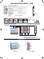
NETWORK ANALYSER
PARAMETERS TABLE . . . . . . . . . . . . . . . . . . . . . . . . . . . . . . . . . . . . . . . . . . . . . . . . . . . . . . . . . . . . . . . . . . . . . . . . . . . . 64
NETWORK ANALYSERS
1RANM8N / 2RAN968N . . . . . . . . . . . . . . . . . . . . . . . . . . . . . . . . . . . . . . . . . . . . . . . . . . . . . . . . . . . . . . . . . . . . . . . . . . . 66
ANALOGUE OUTPUT MODULES . . . . . . . . . . . . . . . . . . . . . . . . . . . . . . . . . . . . . . . . . . . . . . . . . . . . . . . . . . . . . . . . . . 73
MULTIFUNCTION METERS
PARAMETERS TABLE . . . . . . . . . . . . . . . . . . . . . . . . . . . . . . . . . . . . . . . . . . . . . . . . . . . . . . . . . . . . . . . . . . . . . . . . . . . . 64
LED MULTIFUNCTION METERS - TRUE RMS
Single phase 2 DIN modules . . . . . . . . . . . . . . . . . . . . . . . . . . . . . . . . . . . . . . . . . . . . . . . . . . . . . . . . . . . . . . . . . . . . . . . 74
Three phase 2 DIN modules, 72x72 mm and 96x96 mm . . . . . . . . . . . . . . . . . . . . . . . . . . . . . . . . . . . . . . . . . . . . . . . . . . 79
Three phase 6 DIN modules and 96x96 mm . . . . . . . . . . . . . . . . . . . . . . . . . . . . . . . . . . . . . . . . . . . . . . . . . . . . . . . . . . . 84
A LCD TRIFASE CON COMANDO PER MODULI ANALOGICI - VERO VALORE EFFICACE
Three phase 6 DIN modules . . . . . . . . . . . . . . . . . . . . . . . . . . . . . . . . . . . . . . . . . . . . . . . . . . . . . . . . . . . . . . . . . . . . . . . 93
Analogue outputs module - 1RUA1 . . . . . . . . . . . . . . . . . . . . . . . . . . . . . . . . . . . . . . . . . . . . . . . . . . . . . . . . . . . . . . . . . 101
THREE PHASE LCD MULTIFUNCTION METERS - TRUE RMS
Three phase 6 DIN modules . . . . . . . . . . . . . . . . . . . . . . . . . . . . . . . . . . . . . . . . . . . . . . . . . . . . . . . . . . . . . . . . . . . . . . . 102
Three phase 4 DIN modules input 5A by CT . . . . . . . . . . . . . . . . . . . . . . . . . . . . . . . . . . . . . . . . . . . . . . . . . . . . . . . . . . 110
Direct input 10A - 16A - 32A - 63A . . . . . . . . . . . . . . . . . . . . . . . . . . . . . . . . . . . . . . . . . . . . . . . . . . . . . . . . . . . . . . . . 116
DC version . . . . . . . . . . . . . . . . . . . . . . . . . . . . . . . . . . . . . . . . . . . . . . . . . . . . . . . . . . . . . . . . . . . . . . . . . . . . . . . . . . 123
LCD 4 LINES (LED 7 DISPLAY) MULTIFUNCTION METERS - TRUE RMS
Three phase 72x72 mm and 96x96 mm . . . . . . . . . . . . . . . . . . . . . . . . . . . . . . . . . . . . . . . . . . . . . . . . . . . . . . . . . . . . . . 128
SOFTWARE USE . . . . . . . . . . . . . . . . . . . . . . . . . . . . . . . . . . . . . . . . . . . . . . . . . . . . . . . . . . . . . . . . . . . . . . . . . . . . . . . . 136
COMPUTER INTERFACE . . . . . . . . . . . . . . . . . . . . . . . . . . . . . . . . . . . . . . . . . . . . . . . . . . . . . . . . . . . . . . . . . . . . . . . . 138
63
03 multifunzione GB 2011_digitali 24/05/11 14.28 Pagina 64
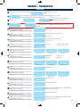
64
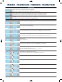
1RANM23
2RAN72C
2RAN96C
2RAN...C-C100
2RAN72C485
2RAN96C485
2RAN...C485-C100
1RANM6
2RAN96
1RANM6R
2RAN96R
1RANM6C
2RAN96C
1RANM6CS
2RAN96CS
1RANM6C485
2RAN96C485
•
•
•
•
•
•
•
•
•
•
•
•
•
•
•
•
•
•
•
•
•
•
•
•
•
•
•
•
•
•
•
•
•
•
•
•
•
•
•
•
•
•
•
•
•
•
•
•
•
•
•
•
•
•
•
•
•
•
•
•
•
•
•
•
•
•
•
•
•
•
•
•
•
•
•
•
•
•
•
•
•
•
•
•
•
•
•
•
•
•
•
•
•
•
•
•
•
•
•
•
•
•
•
•
•
•
•
•
•
•
•
•
•
•
•
•
•
•
•
•
•
•
•
•
•
•
•
1
1
2
2
•
•
•
•
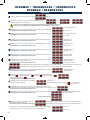
2 DIN
2 DIN
•
•
72x72 / 96x96
6 DIN / 96x96
1RANM6CS485
1RANM2CT
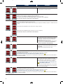
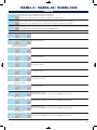
DC Voltage 800 V max
DC Voltage ..../100V by divider
DC Current .../60mV
Bidirectional power (kW)
Bidirectional Total Energy (import/export)
Bidirectional Ampere-hour Ah (import/export)
Harmonic distorsion
•
Total Harmonic distorsion
•
Voltage / Current crest factor
•
Active Energy 4 tarifs (+/-)
•
Reactive Energy 4 tarifs (+/-)
•
Total integration time (15min)
10,15,20,30,60min selectable
Voltage phase-neutral
•
Voltage phase-phase
•
Medium phase voltage
•
Current (direct insertion)
Current (insertion by CT)
•
Current on neutral
•
Medium Current
•
Power Factor
•
Total Power Factor
•
Apparent Power
•
Total Apparent Power
•
Active Power (+/-)
•
Total Active Power (+/-)
•
Reactive Power
•
Total Reactive Power
•
Frequency
•
Total Active Energy (import) resettable
•
Relative Active Energy
•
Total Active Energy (export) resettable
•
Total Reactive Energy resettable
•
Total working hours
•
Partial working hours resettable
•
Acoustic pre-alarm
Phase sequence
•
Voltage asimmetry
OUTPUT RELAY (alarm threshold)
•
MODBUS SLAVE RTU RS232
MODBUS SLAVE RTU RS485
•
BLUETOOTH ACCESS (max 10 meters - Class 2) Baude rate 115200
PERMANENT MEMORY (EEPROM)
•
selectable
400V insertion, 3 or 4 wires, 2 or 3 systems (H1)
selectable
VT..../100V, 3 or 4 wires, 2 or 3 systems (0...9,9kV) (H2)
VT..../100V, 3 or 4 wires, 2 or 3 systems (10...100kV) (H3) selectable
Software on www.revalco.it
•
Option Split Core CT (up to 100A)
Option ETHERNET or PROFIBUS
Dimensions in mm
8 DIN / 96x96
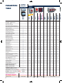
SINGLE
PHASE
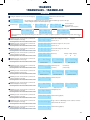
1RANM2
1RANM8N
2RAN968N
PARAMETERS
TABLE
NETWORK
ANALYSER
THREE PHASE
03 multifunzione GB 2011_digitali 24/05/11 14.28 Pagina 65
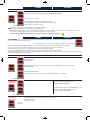
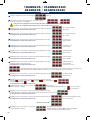
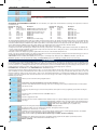
2RAE96L4C
2RAE72L4C
2RAE96L4CS
2RAE96L4C485
2RAE72L4C485
2RAE96L4CS485
1RAEM410C485 - 1RAEM416C485
1RAEM432C485 - 1RAEM463C485
1RAEM410CS - 1RAEM416CS
1RAEM432CS - 1RAEM463CS
1RAEM410C - 1RAEM416C
1RAEM432C - 1RAEM463C
1RAEM4CHDC
1RAEM4CSHDC
1RAEM4C485HDC
1RAEM4CS485HDC
1RAEM4CDC
1RAEM4CSDC
1RAEM4C485DC
1RAEM4CS485DC
1RAEM4CS485
1RAEM4CS485-C100
1RAEM4C485
1RAEM4C485-C100
1RAEM4CS
1RAEM4CS-C100
1RAEM4C
1RAEM4C-C100
1RAEMBL485
1RAEMCS485
1RAEMC485
1RAEMCS
1RAEMC
1RAEM
1RANM6C232
1RANM6CS485
2RAN96CS485
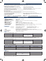
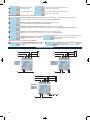
MULTIFUNCTION METERS
THREE PHASE A.C. AND SINGLE PHASE D.C. VERSIONS
•
•
•
•
•
•
•
•
•
•
•
•
•
•
•
•
•
•
•
•
•
•
•
•
•
•
•
•
•
•
•
•
•
•
•
•
•
•
•
•
•
•
•
•
•
•
•
•
•
•
•
•
•
•
•
•
•
•
•
•
•
•
•
•
•
•
•
•
•
•
•
•
•
•
•
•
•
•
•
•
•
•
•
•
•
•
•
•
•
•
•
•
•
•
•
•
•
•
•
•
•
•
•
•
•
•
•
•
•
•
•
•
•
•
•
•
•
•
•
•
•
•
•
•
•
•
•
•
•
•
•
•
•
•
•
•
•
•
•
•
•
•
•
•
•
•
•
•
•
•
•
•
•
•
•
•
•
•
•
•
•
•
•
•
•
•
•
•
•
•
•
•
•
•
•
•
•
•
•
•
•
•
•
•
•
•
•
•
•
•
•
•
•
•
•
•
•
•
•
•
•
•
•
•
•
•
•
•
•
•
•
•
•
•
•
•
•
•
•
•
•
•
•
•
•
•
•
•
•
•
•
•
•
•
•
•
•
•
•
•
•
•
•
•
•
•
•
•
•
•
•
•
•
•
•
•
•
•
•
2
2
•
•
•
•
•
•
•
•
•
•
•
•
•
•
•
•
•
•
•
•
•
•
•
•
•
•
•
2
•
•
•
•
•
•
•
•
•
•
•
•
•
•
•
•
•
•
•
•
•
•
•
•
•
2
2
1
•
•
•
•
•
•
•
1
•
•
•
•
1
1
1
1
1 1
2
2
•
•
•
•
•
•
•
•
•
•
•
•
•
•
•
•
•
•
•
•
•
•
•
•
•
•
•
•
•
•
•
•
•
•
•
•
•
•
•
•
•
• 96x96
6 DIN
6 DIN / 96x96
4 DIN
72x72 / 96x96
•
96x96
65
03 multifunzione GB 2011_digitali 24/05/11 14.28 Pagina 66
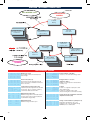
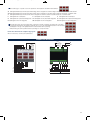
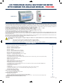
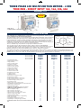
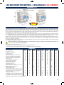
NETWORK ANALYSERS 1RANM8N / 2RAN968N
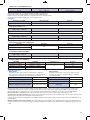
DIMENSIONS in mm
91 +0,8
58
A
45
85
140
The 140 mm dimensions correspond to 8 DIN modules
Weight: 0,61 Kg
91 +0,8
89
A = 97,3 without terminals cover
A = 116,5 with terminals cover
Weight: 0,55 kg
96
96
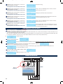
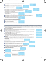
INSTALLING AND CONNECTING
INSTALLATION PROCEDURE
1. Mount the instrument on DIN rail
2.
Turn power off before connecting the instrument to current transformers and/or voltage connections.
3.
Connect current lines to built-in current transformers (CTs). (OPTIONALY). Take care to orient the CTs correctly. Connect the voltage wires to the voltage
measurement inputs. Start with the N wire.
4. Connect digital outputs (relay output terminals) to the quipment (if applicable).
5. Connect digital input port to the equipment (if applicable).
6. Connect RS 485 port to the communication network. Verify connect polarization.
7. Power on the instrument
CONNECTION - MEASUREMENT
The instrument incorporates internal current transformer (5 A input current), together with accompanying burden resistor. Pay attention to the polarity of current phases – they
need to match the polarity of voltage phases. Instrument monitor will report incorrect power polarity otherwise. For extending voltage and current measuring range, use appropriate voltage and current transformers and set correct voltage and current transformation factors. Primary of voltage transformers have to be rated to handle line voltages
and secondary have to match selected instrument voltage range. It is necessary to protect instruments voltage inputs with external fuses or circuit breakers. (not show in
connection diagrams), 1 A or smaller fuses with 10 kA interr. current rating. Output of external current transformer will produce dangerous voltages if left open while current
is flowing through primary winding. Do not disconnect CT output while it’s connected to the live circuit to prevent damage to the CT or the operator.
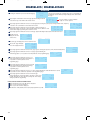
TROUBLESHOOTING INSTALLATION PROBLEMS
In the case of incorrect power please check:
- verify that the instrument is showing the same current as measured in the 5 A CT loop. If this is not the case, verify current transformation factor set on instrument
If this factor is set correctly, check the current harmonics.
- verify that the CTs are wired to the correct phases and oriented to match voltage phase orientations.
- verify the setting on the instrument (3-wire, 4 wire or Aaron) match instruments connection scheme.
In the case of inverse polarity of power (on all phase), use option Invert. Pwr. Sign in System setting configuration menu.
LEDS: YELLOW = comunication activity; RED = digital output status or energy pulse output indicators
NETWORK COMMUNICATION
MODBUS PROTOCOL: RAN provides serial communication interface to other systems connected on MODBUS network. MODBUS is standard communications protocol
in industry, allowing connecting industrial electronic devices across the network. RAN implements RTU serial transmission mode with CRC (cyclic redundancy check) error
correction. ASCII mode is not supported. This allows remote reading and configuring of the meter by a MODBUS controller or PC with special control program. The communication protocol is a subset of Modicon MODBUS, OSI model level 7, providing client/server communication. Client role is provided by the master of network and the
slave nodes as servers. The protocol is a master/slave protocol. Only one master and up to 247 slaves can be connected to the RS485 network at a time.
MODBUS communication is always initiated by a master (controller). Slaves never transmit data without a request, and never communicate between each other. Only one
transaction is active at a time. The master always addresses one or all slaves (the master doesn’t have an address). The master can address each slave individually (unicast mode). Conversation consists of request from the master and reply from the slave. Address of ‘0’ is used for addresing all slaves at the same time (broadcast mode).
Each device on MODBUS network must be assigned a unique address between 1 and 247. More than two devices on the same network with the same addresses, the
communication will fail. RAN sends and receives data in fixed format. Data byte is binary coded and transmitted with least-significant bit first.
The baud rate is programmable as 4800 bps or 9600 with 8 bit data and 1 stop bit.
Available baud rates: 2400, 4800, 9600, 19200, 38400, 57600
Available formats: none parity / 1 stop bit, none parity / 2 stop bits, even parity / 1 stop bit
RS-485 CONNECTION: RS485 output drivers on RAMN8 supports up to 32 devices at a time, often it is necessary to install repeaters in MODBUS network where more
than 32 devices are installed. Single pair of wires is used for connection (2-wire connection system). It is recommended to use screened twisted-pair cable to minimize
noise-related signal errors. The cable screen must be connected to the connector housing (e.g. ground) at one side only (preferably at the controller/master). Maximum
distance for reliable communication is 1000 m (baud rate 9600 ,2x1.5mm2 gauge). RS-485 requires line termination with two 100..150 Ω/0.5 W resistors. Install one resistor at the controller/master input/output and the other at the most remote device (at each extremity of the cable).
Visit web page http://www.modbus.org for more information about MODBUS network, hardware and software specifications.
It is possible to use standard PC, equipped with suitable program, as a MODBUS controller/master with an RS-485 driver/converter (two-wire, half duplex mode).
Available RS-232 to RS-485 converters handle data direction control automatically.
TROUBLESHOOTING COMMUNICATION PROBLEMS: If Power monitor doesn’t communicate with the controller, please check:
- Verify the instrument
- Examine the interconnection cable
- Check that termination resistors ( if installed and correct values)
- Verify that communication hardware is properly installed and working (PC or MODBUS controller
- Verify entered registers addresses
- Measure polarisation (d.c.) voltages present on a MODBUS network between D0(+) and D1(-), they should be lower than 7 V d.c.( toward COM/GND)
- If communication fails from time to time, the probable cause is noise on the network. Locate the noise source and remove the cabling from it, lower communication speed,
use lower termination resistance.
- Make sure that the number of devices on a MODBUS network doesn’t exceed maximum allowed (32 for the standard version of instrument, without repeater).
- Verify that a MODBUS network length doesn’t exceed maximum allowed.
- If other devices installed in the network, verify that they conform to MODBUS.
66
03 multifunzione GB 2011_digitali 24/05/11 14.28 Pagina 67
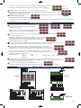
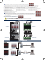
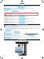
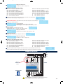
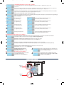
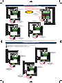
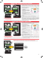
CONNECTION DIAGRAMS
A
external source
(10...30VDC)
Three-phase with neutral 3N3E (4 wires)
LOAD
LOAD
13 14
DIGITAL
INPUT
Three-phase without neutral 3-2E
(Aaron, balanced load)
B
U1
-C
U2
U3
U1
N
Output
digital BUS
for analogue
modules
15 17 19
22
24
23
U2
U3
26
25
15 17 19
21 22
U3 N
26
23
27
Three-phase without neutral 3-2E
(Aaron, balanced load)
LOAD
LOAD
DIGITAL INPUT
external source (10...30VDC)
U2
Three-phase without neutral
3-2E (Aaron, balanced load)
voltage transformers connection
27
Three-phase without neutral 3-3E
(3 wires, balanced load)
15
17
19
21
15
17
19
21
15
17
19
U1
U2
U3
N
U1
U2
U3
N
U1
U2
U3 N
Three-phase with neutral
3N3E (4 wires)
voltage transformers connection
B
U1
N
Three-phase without neutral
3-3E (3 wires, balanced load)
voltage transformers connection
Three-phase with neutral
3N3E (4 wires)
voltage transformers connection
Three-phase
with neutral
3N3E (4 wires)
Three-phase without neutral 3-3E
(3 wires, balanced load)
voltage transformers connection
21
Three-phase without neutral 3-2E
(Aaron, balanced load)
voltage transformers connection
Fuse 2A
(option)
SERIAL COMMUNICATION
RS485
+
-
Scheme n. 1: Connection between instruments
and PC for distances up to 800m
RS232
Max 800 m
A
LOAD
Three-phase without neutral 3-3E
(3 wires, balanced load)
LOAD
Fuse 2A
(option)
0,5A-100V
+
2RAN968N
1RANM8N
Max 15 m
Telephone Line
RS232
RS232
Max 15 m
Max 15 m
RS485
1RINT
Scheme n. 2: Connection via Modem
67
03 multifunzione GB 2011_digitali 24/05/11 14.28 Pagina 68
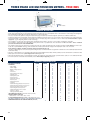
INTRODUCTION
RAN is a quadrant power and energy meter for replacing many separate measuring instruments, like ammeters, voltmeters, power factor and power meters, energy counters, etc. The instrument can be used as a single phase or 3-phase meter (aron, star or delta connection).
Instrument performs the following simultaneous measurements:
- true RMS voltage, current measurements
- frequency and phase angle measurements
- system voltage and current and neutral wire current (in 3phase systems)
- voltage phase sequence (in 3phase systems)
- 4 quadrant power measurements, phase and total power and power factor
- voltage and current THD and harmonic components (up to 31st component),
- phase voltage and current crest factor measurement,
- active and reactive energy counting,
- current maximum and power inside integration period.
- current peaks ,voltage sags and dips and thd peaks.
-power on demand (connecting and disconnecting loads ,for reducing peek power )
Other instrument features:
- direct connection of current inputs or to current transformers with 5 A output (no problems with wiring positioning and burden resistor)
- wide voltage range from 0 V to 500 V, extended with voltage transformers
- active and reactive energy logging (optionally with built in 32kbyts memory ,up to 42 days of integration period of 15 minutes, with time stamp)
- optionally RealTimeClock(RTC) with battery
- RS485 communication port compatible with industry-standard MODBUS protocol,
- 4 opto-insulated configurable digital inputs
- 2 digital configurable outputs
- backlight LCD with 4x20 characters
Standards: EN62053-21:2003-1 Class 1 for static active energy meters
EN62053-21:2003-1
Class 2 for static reactive energy meters
EN 61326
Electromagnetic compatibility (EMC)
EN 61010-1
Safety (LVD) CAT II 600V /CAT III 300V
TECHNICAL SPECIFICATIONS
GENERAL:
- POWER SUPPLY VOLTAGE
- PROTECTION CLASSIFICATION
- POLLUTION / PROTECTION DEGREE
- MEMORY / LED
- OVER VOLTAGE CATEGORY
- LOAD
- DIMENSIONS / WEIGHT
- TEMPERATURE CONDITIONS
- OPERATION CONDITIONS
- STORAGE CONDITIONS
MEASURING SYSTEM:
- CONFIGURATION
3 voltage inputs
3 current inputs
- SYSTEM
- MEASURING PRINCIPLE
- DISPLAY UPDATE
180 V a.c. ÷ 260 V a.c., 50 Hz/60 Hz
double insulation
3 / IP 40
EEPROM 2Mbits / Digital outputs status indicator (Alarms or Energy pulses or Power demand)
CAT II 600 V / CAT III 300 V
5 VA max.
1RANM8N = 8 DIN modules - 2RAN968N: 96 x 96 x 105 mm / 0,50 kg
range 0 °C ÷ +40 °C; humidity range 30 %RH ÷ 75 %RH, non-condensing
Working temperature range -10 °C ÷ +50 °C. Maximum relative humidity 85 %RH (0 °C ÷ +40 °C), non-condensing
Temperature range -10 °C ÷ +70 °C
Maximum relative humidity 90 %RH (-10 °C ÷ +40 °C); 70 %RH (+40 °C ÷ +70 °C)
Voltage input loading: less than 0.1 VA
Line-to-neutral input impedance is 520 kΩ.
Line-to-line input impedance is 1 MΩ.
Voltage input overload: ×1.2 Un , ×2 Un (for <2 sec)
Current transformer (In= 5A)
Current input loading: less than 0.1 VA
Current input overload: x2 In , ×40 In (for < 0.5 sec)
All system with or without current and/or voltage transformers ,balanced or unbalanced load.
Single phase (1N1E); 3-phase (3-2E, Aaron); 3-phase (3-3E, with no neutral); 3-phase (3N3E, with neutral)
TRMS ,4 quadrants, 10 periods, 128 scans/period
1 update/s, harmonics 1 update/2 s
VOLTAGE:
- TRMS PHASE TO NEUTRAL VOLTAGE LX – N, AC
Nominal input range (V)
Phase to neutral voltage range (V)
140 / 280 / 500
0.00 UN ÷ 0.14 UN
140 / 280 / 500
0.15 UN ÷ 1.10 UN
Resolution (V)
0.1
Accuracy
±0.6 V
±0.5 V
Starting voltage: 0.01 UN
Voltage crest factor is 1.5 × UN (measuring range). Over-range indication with ↑↑↑ mark. Over-range indicator appears when line voltage is out-of-range.
Accuracy apply for frequency range 45.00 Hz ÷ 65.00 Hz. Line-to-neutral input impedance is 600 kΩ. Line-to-line input impedance is 1200 kΩ.
- TRMS PHASE TO PHASE VOLTAGE LX – LY, AC
Nominal input range (V)
Phase to Phase voltage range (V)
Resolution (V)
0.00 UN ÷ 1.10 UN
0.1
140
280
Accuracy
±(1.0 % + 0.2 V)
500
Input voltage range: LX – N = 500 VRMS (single phase);
±(1.0 % + 0.5 V)
±(1.0 % + 1.0 V)
290 VRMS (3-phase);
LX – LY = 500 VRMS
- VOLTAGE INPUT TRANSFORMATION FACTOR
Nominal input range (V)
Factor
Comment
0.0 ÷ 140.0
1× ÷ 1279×
140 kV @ 110 V input
0.0 ÷ 280.0
1× ÷ 612×
140 kV @ 230 V input
0.0 ÷ 500.0
1× ÷ 351×
140 kV @ 400 V input
Starting voltage: 0.01 UN * VTF. Voltage TF and current TF are linked together, their product is limited to 20 MW per phase.
CURRENT:
- TRMS CURRENT
Current range (A)
0.0 – 0.049
0.050 ÷ 6.200
Resolution (A)
0.001
Starting current: 0.04 IN (=0.02A @ direct 5A input)
Nominal current input range is 0 A ÷ 5 A (IN). Current crest factor is 2.0 × IN. Over-range indication with ↑↑↑ mark.
Accuracy apply for frequency range 45.00 Hz ÷ 65.00 Hz.
68
Accuracy
±0.005 A
±0.5 %
03 multifunzione GB 2011_digitali 24/05/11 14.28 Pagina 69
- CURRENT INPUT TRANSFORMATION FACTOR
Nominal current range (A)
Factor
Comment
0.0 ÷ 5.0
5 A/5 A ÷ 10000 A/5 A
20 MW max./phase
Starting current: 0.04 IN * CTF (e.g =0.4A @ 5A input through 100/5 current transformer)
Voltage TF and current TF are linked together, their product is limited to 20 MW per phase.
Displayed voltage are max.140 kV (@ max.VTF). Displayed current are max. 10 kA (@ max.ITF).
VTF and ITF product is limited to 20 MW / phase power ,60 MW total power.
FREQUENCY
Frequency range (Hz)
Resolution (Hz)
Accuracy
45.00 ÷ 65.00 (for voltage range 0.15 Un < U )
0.01
±0.04 Hz
Voltage range * voltage TF *
current range * current TF
Resolution (W, VA, VAr)
Accuracy
0.0 ÷ 20000000.0
0.1
±(0.4 %FS + 0.5 % of reading)
Voltage range * voltage TF *
current range * current TF
Resolution (W, VA, VAr)
Accuracy
0.0 ÷ 60000000.0
0.1
±(0.5 %FS + 1 % of reading)
POWER AND ENERGIES
- PHASE ACTIVE POWER (P, Q, S)
- TOTAL ACTIVE POWER (Pt, Qt, St)
Accuracy apply for: voltage range 0.15 Un < U < 1.10 Un; current range 0.01 In < I < 1.2 In; power factor 0.40 ÷ 1.00; frequency range 45.00 Hz ÷ 65.00 Hz
- PHASE POWER FACTOR & TOTAL POWER FACTOR
PF range
Resolution
0.00 ÷ 0.39
Accuracy
±0.04
0.01
0.40 ÷ 1.00
±0.02
Accuracy apply for: voltage range 0.15 Un < U < 1.10 Un; current range 0.01 In < I < 1.2 In; frequency range 45.00 Hz ÷ 65.00 Hz
- ACTIVE ENERGY AND REACTIVE ENERGY
Voltage range * voltage TF *
current range * current TF
Resolution (Wh - VArh)
Accuracy
0 ÷ 1.000.000
10
±(1.5 % + 3 dig)
THD & HARMONICS
- VOLTAGE / CURRENT THD & HARMONICS
VOLTAGE
CURRENT
Resolution (%)
harmonics U < 0.05 Un
harmonics I < 0.05 Un
harmonics U >= 0.05 Un
harmonics I >= 0.05 Un
THD
THD
±5 %
±1 %
0.1
±1 %
DIGITAL INPUTS/OUTPUTS
- DIGITAL INPUTS
Configurable as 40-bit counters triggers (increments of 0.01 ... 100/ pulse of
power or any other counting or for counting working hours of external equipment)
or as integration period synchronization or tariff selectors (2 or 4 tariffs)
input voltage (max. AC/DC)
Accuracy
- DIGITAL OUTPUTS
Configurable as alarms (voltage, current, active or reactive power, freq.
out of range), as energy pulse output (0.001 kWh/pulse...1 kWh/pulse)
or power demand outputs
25 V
switching voltage (max.AC)
25 V
threshold voltage
6V
switching current (max.)
1A
input impedance
2.2 kΩ
pulse out width
approx. 50 ms
activation sequence (IP sync.and counters)
LO-> HI -> LO transition
(min. 50ms HI pulse width)
output type
Relay, normally open
(N.O.)
MEASUREMENT METHODS
Measurement methods are based on the digital sampling of the input signals. Each input (3 voltages and 3 currents) is sampled 128 times in each input cycle.
Sampling frequency depends on the frequency at the synchronisation input (one of the 3 voltage inputs). Sampling period is 200mS (e.g. 10 cycles @50Hz).
Basic measured values are calculated at the end of each sampling period. FFT based results are calculated on every 8th input cycle (every 160ms@50Hz).
Measured values (Basic calculations): Phase voltage; Phase current; Phase active power; Phase to phase voltage; Neutral conductor current.
Calculated values (using measured values): Phase apparent power; Phase reactive power; Phase power factor; Phase voltage crest factor; Phase current crest factor;
Total active power; Total reactive power; Total apparent power; Total power factor.
In a 3wire systems connection, the following values are not available for displaying: neutral conductor current; phase powers and power factor; crest/thd/harmonics of not
applicable signals.
Additional calculation (using FFT transformation): Phase voltage THD; Phase current THD; Phase voltage individual harmonics; Phase current individual harmonics
Energy are calculate every 1 second ,based on average power during all sampling periods of 200 mS (e.g. 5 samples periods/second @50Hz). Energy values are in Ws
or VArs.
69
03 multifunzione GB 2011_digitali 24/05/11 14.28 Pagina 70
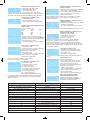
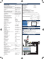
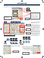
OPERATION - INSTRUMENTS SCREENS LOOPS
Power ON
INFO SCREENS LOOP
MEASUREMENTS
SCREENS
U, I, P, Uu
Metering
U 1/2/3 and I 1/2/3
Total Harmonic Distorsion
and Harmonics
P, Q, S, Pf
Phase Power
U and I
Total Harmonic Distorsion
and Crest Factor
Pt, Qt, St, Pft
Totals Power,
Frequency, Tariff
kWh and kVArh
Total Energy
Ptmax and Qtmax
Maximum and Last IP
imp / h: min
Counters 1/2
Imax
Maximum phases Current
kWh and kVArh
Energy Tariffs 1/2/3/4
CONFIGURATION
SCREENS
MEASUREMENTS SCREENS
V
A
W
Vv
230.8
2.583
518.7
399.8
232.4
2.622
542.4
402.5
229.8
2.557
486.0
398.0
W
VA
VAr
Pf
518.7
596.2
293.9
0.87i
542.4
609.4
277.8
0.89i
486.0
587.6
330.2
0.84i
Metering (U, I, P, Uu)
Phase Voltage, Current, Power and phase to
phase Voltage
Phase Power (P, Q, S, Pf)
Phase Active, Reactive, Apparent Power and
phase Power Factor (not available in 3wire and
Aaron connection)
TOTAL 4w TR1 13/15m
kW 1.547
VA 1.791 50.02Hz L1
Var 0.902 PfT
0.86I
Totals (Frequency, Tariff, Pt, Qt, St, Pft)
Total Active, Reactive, Apparent Power and Total
Power Factor, Type of connection, Frequency,
current Tariff, remain/selected IP time
KW+
KVAr+
KW+
KVAr+
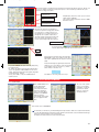
Maximum and Last IP Power
Maximum average Active Positive and Reactive
Power in any IP and in Last elapsed (based on
accumulated IP energy/IP time)
kWh+ tot
kWh- tot
kVArh+ tot
kVArh- tot
>00001207.83 Energy (total/sum. of all tariffs)
00000000.00 cursor ( > ) is on current Active Energy counter
>00000990.42
00000000.00
kWh+
kWhkVArh+
kVArh-
00000807.35
00000000.00 (example for tariff 1)
00000690.26 Number of screens depend of selected number
00000000.00 of tariffs (2 or 4)
TR1
TR1
TR1
TR1
Energy in tariffs 1 to 4 screens
Counters
Count.1:
00000101.50
inc/imp:0.50 Counter 1 is configured as input pulse counter
Count.2: 0000010h52m (pulse weight is 0.50 )
inc/imp: time Counter 2 is configured as time counter
(measure working time of external device activity)
I1 max.
I2 max.
I3 max.
70
max.
max.
lst.
lst.
1.97
1.04
1.63
0.98
2.981 A.
3.018 A
2.756 A
Maximum IP Current
Maximum average Current in any IP
Uthd
UCRf
Ithd
ICRf
3.45
1.40
5.18
1.78
3.26
1.46
6.02
1.83
3.78
1.42
4.59
1.80
Voltage and Current Total Harmonics Distortion
(thd) and Crest Factor (CRf)
U1: 230.8 V thd: 3.45 Voltage or Current Harmonics (example for U1)
h3: 3.12
h5: 0.61 Displayed are odd harmonics (h3 …h13)
h7: 0.18
h9: 0.02 All harmonics (h2…h31) are available through
h11: 0.08 h13: 0.00 MODBUS protocol communication.
03 multifunzione GB 2011_digitali 24/05/11 14.28 Pagina 71
INFO SCREENS LOOP
For quickly reviewed/checked instrument setting ,without to enter in configuration menu, press and hold SEL key for 1 s in any measurement screen. When first information screen is displayed use UP and DOWN keys to browse through instrument settings (abbreviations have the same meaning as in corresponding configuration
screens). Instrument automatically returns from info to measurements 10 seconds after last keys activity.
Communication
information
Press and hold SEL key for one second for entering in
Info Screens Loop and short press SEL key
for Exit from loop
Metering
information
IP and digital inputs
information
Instrument type / version
information
Press UP or DOWN keys
to browse
through info screens
Counters
information
Calibration and
current time/date
Output 1/2
setting information
Recorder status
information
Output 1/2
status information
R E V A L C O
3ph Energy Analyzer
RANM8 ver.: 436/1
ser.no: 00000000
Volt.range:
Voltage TF:
Current TF:
Conn: 4wire
Comm.mode:
Net.addr.:
Baud.rate:
280 V
1 x
5/5A
MODBUS
1
9600
Energy tariffs: 2
IPsync.:
input3
IPlength: 15 min.
IPremain: 11 min.
Instrument information screen
Manufacturer type, version and serial number
of instrument
Metering system information screen (example)
Voltage range, Voltage and Current Transformers
Factors and type of measurement connection
Count.1: STOP
inc/imp: 0.01
Count.2: RUN
inc/imp: time
Record.stat: STOP
Lap rec.no.:
0
Lap occurred:
No
FreeLapRec:
191
Input counters information screen (example)
Counter status, increment factor and mode
(pulse or time counter)
Recorder status information screen (example)
Recorder status, number of stored records and
info of available free records before lap (circular
buffer behavior)
Communication information screen (example)
Communication setting, net address and speed
Out1: alarm>> [OFF]
Ref.inp.:
I1
Ref.val.: 55.00 A
Delay: 05s
Output 1 information (example)
Current output status (OFF/ON), output mode and
information depended about selected mode
IP and digital inputs information screen (example)
Selected number of Tariffs, source for Tariffs
synchronization, IP length (presetted and remain)
Cal.date: 10.08.08
Current date/time:
29.04.09 15:28:34
Calibration and current instrument date/time
Current time/date only on instruments with build in
Real Time Clock
CONFIGURATION SCREENS
To enter in configuration press and hold SEL key for 5 s in any measurement screen.
Use UP and DOWN keys to select configuration submenu and press SEL. In selected configuration submenu use SEL key for selecting one of available parameters
and adjust/modify it with UP and DOWN key. For exit from submenu to main configuration menu and for exit from main configuration menu to measurements, select
EXIT and press UP or DOWN. Instrument automatically returns from configuration menu to measurements 3 minutes after last keys activity.
Exit
> Metering system
Communication.
Digital inputs.
Inputs counters
Digital output 1
Digital output 2
Clear regs./counts.
System settings
Recorder settings
Main configuration screen
UP and DOWN key to move cursor and/or scroll screen through all configuration options.
SEL key to enter in selected submenu
Select EXIT for return in measure
71
03 multifunzione GB 2011_digitali 24/05/11 14.28 Pagina 72
Volt.range:
Voltage TF:
Current TF:
Conn: 4wire
280 V
1 x
5/5A
EXIT
Metering system configuration screen
= Voltage range 140V, 280V or 500V
= Voltage Transformation Factor
= Current Transformation Factor
= select connection, 4wire, 3wire or Aaron
Maximum value of Voltage and Current Transformation Factor are in interaction
and depend of voltage range and max power (20MW per phase, 60MW total)
Comm.mode:
Net.addr.:
Baud.rate:
MODBUS
1
9600
EXIT
Energy tariffs:
IPsync.:
IPlength:
2
input3
15 min.
EXIT
Count.1: STOP
inc/imp: 0.01
Count.2: RUN
inc/imp: time EXIT
Communication configuration screen
= select MODBUS or OFF
= select network address from 1 to 247
= select communication speed 4800 or 9600
Integration period (IP) and digital inputs configuration screen
= select no.of tariffs , 2 or 4
input 1
input 2
tariff no.
OFF
OFF
1
ON
OFF
2
OFF
ON
3
ON
ON
4
= select source for IP synchronization, internal
timer, input 2, input 3 or remote through MODBUS
(internal timer is always active in conjunction with
selected synchronization source)
= select IP time length (10, 15, 20, 30 or 60 min)
Input counters configuration screen
= select STOP or RUN
= select increment factor of counter on every input
pulse or select time for counting time
(hours|minutes) of input activity.
= select STOP or RUN
= select increment factor of counter on every input
pulse or select time for counting time
(hours|minutes) of input activity.
Counter 1 is connected on input 3, counter 2 on input 4.
If IPsync: input 3, counter 1 count IP periods.
Record.mode: STOP
Rec.activ.enr: eP+
Rec.react.enr: --EXIT
Recorder status configuration screen
= select STOP or RUN
= select active energy for recording
eP+, positive active energy
eP-, negative active energy
eP+/-, positive and negative active energy
= select reactive energy for recording
eQ+ , positive reactive energy
eQ- , negative reactive energy
eQ+/-, positive and negative reactive energy
If user STOP and RUN recording with different energy selected, instrument
prompt warning message before execute/store new settings with deleting
old/previous records.
Out1 mode: alarm>>
Ref.inp.:
I1
Ref.val.: 55.00 A
Delay: 05s
EXIT
Alarm is signaled if reference quantity (ref.inp.) is equal/higher or lower than
preset value. Output relay is closed as long as such condition lasts or for
minimum condition time
Output 1 and Output 2 configuration screen
(example for pulse out)
= Out 1/2 mode: pulse output (for ext. energy counter)
Out1 mode: puls.out
Ref.inp.:
Ptot+
= Total Active Positive Energy
Puls.wgt: 2.500 kWh
= select pulse weight (amount energy per pulse)
EXIT
Output relay is closed for approx. 50 ms whenever predefined energy value is reached
Out1 mode: pwr.dem.
Max.IPpwr: 1.000 kW
Con.pwr1.: 2.500 kW
EXIT
Output 1 and Output 2 configuration screen
(example for Power demand)
= Out 1/2 mode: Power demand
= select maximum Power in IP time
= select power of controlled load
(connected on output 1/2)
Output relay is closed if Power trends is lower than preset value (MaxIPpwr).
Relay goes into open state if IP Power trends go higher than preset value.
Connection Power (Con.pwr.) is set for each output independently. Instrument
checks Power on each input every minutes and will disconnect only one load if calculation shows this is adequate (output 1 has priority) and same when the possibility
to reconnect any of the loads.
Clr.energy cnt.
Clr.IP max.
Clr.counters
Clr.rec.data EXIT
Clear registers / counters screen
= clear Energy counters, Total and Tariff Energy
= clear IP max Power and max Current registers
= clear Counter 1 and 2
= clear Energy recorder data/memory
If recorder memory in not empty instrument prompt warning and clear confirmation
message.
System settings screen
Password / Change password
Password DISABLED
User can disable or enable or change password
Change password
for entering in configuration screens. This action
always required entering current password.
Password are four keys (or double keys) sequence.
Initial password is four SEL keys.
Reinit / Invert.Pwr.Signal = toggled on pressing SEL key
Reinit = load default parameters (see default table)
Invert. Pwr. Sign. = inverting powers signs
= adjust instrument time/date
Adj.RTC
EXIT
(only on instruments with build on Real Time Clock)
EXIT
Adjust DATE/TIME:.
29.04.09 15:28:34
Ouput mode
Reference signal
alarm >> (alarm ON, higher or equal the setted value)
see table
alarm >> (alarm ON, lower the setted value)
see table
pulse output (Energy pulse out)
Ptot+ (Total Active positive Energy)
Power demand
Ptot+ (Total Active positive Power)
OFF (force OFF status)
-
ON (force ON status)
-
Reference signal
72
Output 1 and Output 2 configuration screen
(example for alarms)
= Out 1/2 mode: select output function (*see table)
= select reference signal (*see table)
= select reference signal value (alarm threshold)
= select output action delay (1..12 seconds)
(minimum condition time)
Adjust current instrument date/time
(with build on Real Time Clock only)
Use SEL key for moving cursor on desired
date/time part and adjust using UP/DOWN keys.
Select EXIT for save changes and exit.
Referred value units
Wh, kWh ,MWh
Referred value units
Ptot+
Total Active positive Power
W ,kW ,MW
Qtot+
Total Reactive positive Power
Var ,kVAr ,MVAr
I1
Current on line/phase1 (I1)
A ,kA
Ix
Current on any line/phase (I1 or I2 or I3)
A ,kA
U1
Voltage on line/phase1 (U1)
V ,kV
Ux
Voltage on any line/phase (U1 or U 2 or U3)
V ,kV
Freq
Frequency
Hz
03 multifunzione GB 2011_digitali 24/05/11 14.28 Pagina 73
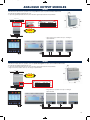
ANALOGUE OUTPUT MODULES
1RUAN3
- With this three modules device it is possible to select four positive DC outputs only, between 0-20mA; 4/20mA: 0-10V;
0-5V through the minidips situated under the cover
- 2 outputs are galvanically insulated from the other 2 and all are galvanically insulated from output RS485
58
Analogue output 3
Analogue output 4
Analogue output 2
SELECTABLE POSITIVE ONLY OUTPUTS
7
8
9
10 11
85
45
12
52,5
NEW
1
2
3
4
5
6
Analogue output 1
- Using 3 devices it is possible to have up to 12 analogue
outputs maximum
1RUAN4
- With this four modules device it is possible to select four positive and negative DC outputs, between 0-20mA; 4/20mA: 0-10V;
0-5V through the minidips situated under the cover
- 2 outputs are galvanically insulated from the other 2 and all are galvanically insulated from output RS485.
- Using 3 devices it is possible to have up to 12 analogue outputs maximum
58
Analogue output 3
Analogue output 4
Analogue output 2
85
7
8
9 10 11 12
NEW
45
SELECTABLE POSITIVE AND NEGATIVE OUTPUTS
1
2
3
4
5
70
6
Analogue output 1
- Using 3 devices it is possible to have up to 12 analogue
outputs maximum
73
03 multifunzione GB 2011_digitali 24/05/11 14.28 Pagina 74
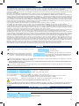
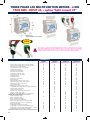
LED MULTIFUNCTION METERS - TRUE RMS
SINGLE PHASE
1RANM2
1RANM2CT
-
Two display 3 digit each
Easy and immediate reading without possible incomprehensions or further elaborations.
The use of one button only permits to change the measurements pages in natural way.
During the program phase, the instrument shows the different possibilities present in the device, so it
is not necessary to have in hands the user’s manual all the time.
The “power supply” page can be used in all the cases on which is important the information of
“power supply loss” (e.g. in refrigerating machines and/or cold storage).
The 2 modules dimension is the right compromise between the necessity to reduce the space and a
good readability of measurements that it is one off the main scope in an electrical net.
The possibility to reset the energy and contemporary the hour/minutes value permits, in easy way, to
see the relative consumption in a fixed time.
1RANM2 model is usable as priority relay 16A
CONNECTION DIAGRAMS
DIMENSIONS in mm
The 35 mm dimension correspond to 2 DIN modules
Weight kg. 0,30
58
6
7
LOAD
5
8
1RANM2CT
LOAD
1RANM2
85
45
35
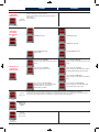
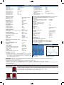
TECHNICAL CHARACTERISTICS
-
-
PARAMETERS
- Ph-N voltage
V
- Current (direct connection)
A
- Current (connection by means of C.T.)
A
- Power factor
ind/cap
- Apparent power
PVA
- Active power
PW
- Reactive power
Pvar
- Frequency
Hz
- Active Energy (resettable capacity)
kW/h
- Reactive Energy (resettable capacity)
kvar/h
- Partial working time (resettable capacity)
hh
- Acoustical pre-alarm
OUTPUT RELAYS (contact 250V-2500W) selectable on principal measures (V-A-Hz-Pw)
Auxiliary power supply
- nominal value U AUX
230V 50/60 Hz
- range
0.9...1.1 UAUX
- max absorbed power
2 VA
Input voltmeter circuit
Ph-N voltage
- direct insertion (Ph-N)
max 300 V
- permanent overload
120%
- thermic overload (1 s)
150%
1,5MΩ Ph-N
- input impedance of voltmeter circuit
Input ammeter circuit
- current:
direct insertion
max 32A
insertion by means of C.T.
5A
- permanent overload
120%
- thermic overload (1 s)
200%
- range adjustment, CT ratio
5...999
Voltage measurement range
- VLN measurement range (voltage phase, direct insertion) 0...250 V
- accuracy class
0.5% f.s ± 2 digit
Current Measurement range:
- measurement range:
direct insertion
0,1...26A
accuracy class on range 0,1... 26A
0.5% f.s ±
74
2
digit
1RANM2
1RANM2CT
•
•
•
•
•
•
•
•
•
•
•
•
•
•
•
•
•
N.C.16A
N.O. 10A
- measurement range:
insertion by means of C.T.
accuracy class on range 0,05...5 A
Frequency Measurement range:
- nominal value
- range
- accuracy class
- response time
Active Power
- range
direct insertion
insertion by means of C.T.
- accuracy class
Reactive Power
- range
- accuracy class
Apparent Power
- range
- accuracy class
Active Energy (Wh)
- resettable visualization
- calculating period
- energy counting
direct insertion
insertion by means of C.T.
- accuracy class with current 0,05...1.0 In
0,05...5A
0.5% f.s ± 2 digit
50/60Hz
45...65 Hz
0.3% vm ± 1 digit
< 300mS
8 kW
500 kW
1% f.s ± 2 digit
250 kvar
1% f.s ± 2 digit
250 kVA
1% f.s ± 2 digit
Two separate
15 minutes
9,99 / 999 kWh
9,99 / 999 kWh
2% fs ± 2 digit
03 multifunzione GB 2011_digitali 24/05/11 14.28 Pagina 75
Reactive Energy (varh)
- energy counting resettable
9,99 / 999 kvarh
- calculating period
15 minutes
- accuracy class with current 0.05...1.0 In
2% fs ± 2 digit
Power Factor
0...1...0
- range cosϕ
- accuracy class with current 0.1...1.0 In and voltage 0.8...1.2 Un 2% fs ± 2 digit
Working time
- Partial working time
hh:mm (from previous reset)
Digital filter
- Average
1...15
Compatible current transformers
- Nominal current
5A
- Ratio
1...200
Visualization
- display
2 numerical lines
- number of characters
6 on two lines
- colour
RED
Mechanical characteristics
- mounting
on DIN rail DIN50022
- protection
IP20/ frontal IP30
Electrical characteristics, options
Galvanic insulation
- alarm relay coil-contact
3kV
Relay characteristics (1RANM2)
- N.C. contact maxV....maxI....maxP
250VAC,16A (resistive load), 2500W
Relay characteristics (1RANM2CT)
- N.O. contact maxV....maxI....maxP
250VAC,10A (resistive load), 2500W
MEASUREMENT’S TYPOLOGY
True RMS up to the 20th harmonic wave
Crest factor up to 2,5
(Voltage and Current)
ALARM RELAYS
One relay with normally closed or normally open contact.
Possibility to set the interventation threshold:
- “Hi” more of .... (>) and “Lo” less of... (<)
- delayed to the excitation “ - - - ” or to the disexcitation “ - - - ”
MEASURE’S CHANEL TO WHICH THE THRESHOLD IS REFERRED:
- min or max line Voltage
- min or max line Current
- min or max Frequency (1RANM2CT only)
- min or max Active Power
When loads more than 10A are present, it is necessary to use
(relays) auxiliary contactors
Environment conditions
Ambient temperature:
- nominal temperature
- range
- storage temperature
- humidity
- atmospheric pressure
0...+45 °C
-5...+55 °C
-10...+70 °C
10...95 %
70...110 kPa
Standards CEI
- Safety CEI EN 61010-1 300V CAT III
- Accuracy class CEI EN 60688
- Electromagnetic compatibility (immunity) CEI EN 61000-6-2 (ex EN 50082-2)
- Electromagnetic compatibility (emission) CEI EN 61000-6-4 (ex EN 50081-2)
- Protection IP CEI EN 60529
USABLE AS:
- motor protection
- overload
- low consumption
- not presence of phase
- priority relay
- anomaly of frequency
- high consumption
- min voltage
1RANM2
1RANM2CT
- Single phase multifunction meter direct insertion, 230V - 26A
(usable on domestic homes and low loads)
- Instrument furnished already calibrated with the following data:
selected cource = ACTIVE POWER
maximum threshold = 4,0 kW
acoustic alarm = 8 sec
time isteresis = 10 min
Single phase multifunction meter by means of CT, 230V - from
5A to 1000/5A (for industrial use)
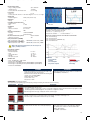
OPERATION: Measurements displaing.
The measurements and signalling pages which appear (pushing and releasing the frontal button) are the following:
PUSHED BUTTON
RELEASED
DESCRIPTION
This FLASHING signal appears only if:
- this page is selected as “default page” (see the correspondent configuration chapter) and the instruments is just light-on or if the
auxiliary supply failed, immediately light-on or the parameters configuration is finished.
After the changement of this page, it disappears from the selection pages.
This page is selected in case of the display’s light is extremely high; selectable as “default page” also.
The sole line light-on, means that the device is in any case working.
“Blank” page
On the upper line the value of the voltage (V) is displayed.
On the downer line the value of the current (A) is displayed.
On the upper line the value of the voltage (V) is displayed.
On the downer line the value of the current (A) is displayed.
The decimal point is in function of the selected CT value.
100/5A = 99.9 indication
over 100/5A = 999 indication
voltage / current
75
03 multifunzione GB 2011_digitali 24/05/11 14.28 Pagina 76
1RANM2
PUSHED BUTTON
RELEASED
1RANM2CT
DESCRIPTION
On the downer line the value of the frequency (Hz) is
displayed with one decimal resolution
frequency
On the downer line the value of the Active Power (kW) is displayed.
1RANM2 model has always the centesimal resolution (<9,99 kW max)
Active Power can be POSITIVE or NEGATIVE depending by the sense of the current.
If a red point (in the lower part of the extreme right) is light-on, it means that the value is NEGATIVE.
It is necessary to verify the corrent insertion of the instruments.
active power
Power Factor (Cos ϕ).
It is the Phase displacement between voltage and current.
When the showed value is 1,00 PF indication means that the phase displacement is ZERO (not capacitive or inductive but resistive only).
Phase displacement is POSITIVE (current is delayed to the voltage = Inductive).
Phase displacement is NEGATIVE (voltage is delayed to the current = Capacitive).
It is necessary to verify the corrent insertion of the instruments.
power factor
reactive power
On the downer line the value of the Reactive Power (kvar) is
displayed, with or without decimal points (decimal or centesimal resolution). The Reactive Power can be POSITIVE or
NEGATIVE like the Power Factor (Cos ϕ).
If a red point (in the lower part of the extreme right) is light-on,
it means that the value is NEGATIVE. It is necessary to
verify the corrent insertion of the instruments.
On the downer line the value of the Apparent Power (kVA) is
displayed, with or without decimal points (decimal or centesimal resolution).
Apparent Power is always positive (Vrms x Irms).
apparent power
active energy
On the entire display the Active Energy (kWh positive and/or negative) value appears, 6 numbers.
The example shows 134.261 kWh.
To grant long duration of the instrument’s memory, automatic backup is effected every 15 minutes.
If the instrument is light-off, the sum related to the last 15 minutes can be losed.
The sum can be resetted by a long pressure of the frontal button. The value starts to flash, and after few seconds the numbers
show permanentely ZERO.
On the entire display the Reactive Energy (kvarh positive
and/or negative) value appears, 6 numbers. The example
shows 1583 kvarh. To grant long duration of the instrument’s
memory, automatic backup is effected every 15 minutes.
reactive energy
If the instrument is light-off, the sum related to the
last 15 minutes can be lossed.
The sum can be resetted by a long pressure of the frontal button. The value starts to flash, and after few seconds the numbers show permanentely ZERO.
partial hour-counter
76
On the entire display the Partial Hour-counter(hh) appears, 6 numbers.
The example shows 4.320 hours from the last zeroing.
To grant long duration of the instrument’s memory, automatic backup is effected every 15 minutes.
If the instrument is light-off, the sum related to the last 15 minutes can be losed.
The sum can be resetted by a long pressure of the frontal button. The value starts to flash, and after few seconds the numbers
show permanentely ZERO.
03 multifunzione GB 2011_digitali 24/05/11 14.28 Pagina 77
1RANM2
PUSHED BUTTON
RELEASED
1RANM2CT
DESCRIPTION
Situation of output relay
Off = rest relay (closed contact), this situation is present with light-off instrument
On = Active relay (open contact)
Note: all the pages flash during the interventation of threshold
The showed light point shows that the interventation condition is present.
This point light-on on all the other pages too.
output situation
The activation of relay is evidenced by the display’s flash, every page is displayed.
The threshold interventation can be delayed during the configuration phase.
The immediate overpassing of the selected value is displayed by the presence of a red point situated on the extreme right of the upper diplay, contemporary an
acoustic alarm (pre-alarm) is emitted. This acoustic signal continue until the interventation of the relay.
The acoustic alarm is always inhibited within the firts 10 seconds starting from the powering of the device.
1RANM2
1RANM2CT
PROGRAMMING: Make a long pressure (4 seconds about) on the frontal button staying in a page where the reset of parameter is not allowed.
So not on the pages of Energy and Hour-counter.
The following page appears: the flashing point means that it is possible now the configuration.
After 4 seconds the pages with configuration parameters start to be displayed; one page every 4 seconds showing the actual selected value.
If it is necessary to see the values without any modification don’t touch nothing until the automatic end of the showed pages.
To change the values of parameters, it is enough to press the button while this parameter is displayed.
The value change immediately and closed to him a flashing point appears meaning that the value is in modification phase.
To fast forward maintain pressure on the front button. When the needed value is displayed release the button and after 4 seconds the further parameter appears, the
modified value is automatically saved permanentely.
DEFAULT PARAMETER
POSSIBLE VALUES
DESCRIPTION
Output will be activated when the value of selected measure will be HIGHER than the value of selected threshold
(MAX THRESHOLD).
Default setting.
Output will be activated when the value of selected measure will be LOWER than the value of selected threshold
(MIN THRESHOLD).
Output will be NEVER activated.
In this case, all the parameters related to the threshold CANNOT be displayed, so not settable
threshold mode
AVAILABLE IF tSh
IS DIFFERENT
FROM OFF ONLY
The delay time will be applied to the ACTIVATION, the output
light-off after the programmed delay time only.
(DELAYED TO THE EXCITATION).
The delay time will be applied to the DEACTIVATION, the output light-off after the programmed delay time only.
(DELAYED TO THE DISEXCITATION).
delay setting
AVAILABLE IF tSh
IS DIFFERENT
FROM OFF ONLY
It is the delayed value with which the alarm contact come back to the close situation after an eventual interventation.
It is particular usefull to avoid continuous interventations of the device.
Esxpressed in seconds.
Default setting = 600
VALUE
from 0 to 999
delay
77
03 multifunzione GB 2011_digitali 24/05/11 14.28 Pagina 78
1RANM2
DESCRIPTION
DEFAULT PARAMETER POSSIBLE VALUES
AVAILABLE IF tSh
IS DIFFERENT
FROM OFF ONLY
VALUE
from 0 to 255
1RANM2CT
It is the delayed value with which the alarm contact works
after the overpassing of the selected level.
This acoustic signal (pre-alarm) is always present together
with the delay.
Default setting = 8
max sound duration
AVAILABLE IF
tSh IS DIFFERENT FROM OFF
ONLY
VOLTAGE threshold.
VOLTAGE threshold.
CURRENT threshold.
CURRENT threshold.
FREQUENCY threshold.
threshold source
AVAILABLE IF tSh
IS DIFFERENT
FROM OFF ONLY
ACTIVE POWER threshold.
Default setting.
ACTIVE POWER threshold.
“Src” selected for VOLTAGE.
Selection range from 0 to 999 V without decimal
points.
“Src” selected for VOLTAGE.
Selection range from 0 to 999 V without decimal
points.
“Src” selected for CURRENT.
Selection range from 0 to 99,9 A
A“Src” selected for CURRENT.
Selection range from 0 to 999 A with or without
decimal point depending by the selected CT
“Src” selected for FREQUENCY.
Selection range from 0 to 99,9 Hz with decimal
point.
threshold value
“Src” selected for ACTIVE POWER.
Selection range from 0 to 99,9 kW (decimal
point depends by the Power value).
Default setting = 2,80 kW
VALUE
from 1 to 15
“Src” selected for ACTIVE POWER.
Selection range from 0 to 99,9 kW (decimal
point depends by the Power value).
It is the number (n) of single measures effected on the electrical parameter before it’s visualization on the display.
Practically it is the filter of the measure stabilization. The numbering rise up from 1 to 15; more higher is the selected number,
more slow are the eventual variations of reading. This is valid for all the measured parameters.
average
ONE OF THE
AVAILABLE
PAGES
Select the main page that you want to see after the initial powering of the instrument.
Default page
VALUE
from 5 to 999
every 5 steps
current
transformer
secondary 5A
78
Select the ratio .../5A of the current transformer.
03 multifunzione GB 2011_digitali 24/05/11 14.28 Pagina 79
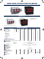
THREE PHASE
+ OPTION “SPLIT CURRENT CT”
- 2 modules DIN (the smaller present on the market) is the best solution in order to save space on cabinets and in meantime to have a good
readability of measures; main scope of multifunction meters in an electrical net.
- Nine red leds with high intensity on three lines, permit to show 3 measurements at the same time.
- Two buttons on front permit to change the measurement pages easily and in natural way.
- During the setting phase, the instrument shows the different possibilities present in the device; so it is not necessary to have in the hands
the user’s manual all the time.
- “Power supply” page can be used in all the cases on which is important the information of “lost power supply” (example in refrigerating
machines and/or cold storage)
- The possibility to reset the energy consumption and time, permits to show in easy way the relative consumption in a certain time
- Current on neutral wire: meaning of Iunbalanced measurement (unbalanced current). It is frequent now, also in normal distribution nets,
the use of devices on which the load is not linear. With the scope to calculate correctly the neutral cable and to verify the correspondence with the project data, measurement of current on neutral ( or unbalanced current measure) become fundamental.
These loads absorb not sinusoidal currents, generating harmonic waves as consequence. Third harmonic waves and their multiples, in a
3phase system, are in phase between them constituting homopolar terns.
In a 4 wire systems these homopolar terns (Io) makes an aritmetical sum and go along
i1A (t)
i1B (t)
i1C (t)
the neutral cable; as result the current on it is: Ino=3*Io. So, as example, a third harmonic component I3, present on 3 phases with amplitude 40% respect to the fundamental, causes on neutral a current higher than the fundamental (1,2*Inom)
It was in the past a rare situation. Current on neutral was caused principally by the 0
unbalanced loads and the solution was to calculate the section of neutral cables equal
i3A (t)
i3B (t)
i3C (t)
or less to the phase cables section.
Now the standard CEI 64-8 art. 524.3, explain well that: neutral cable in multiphase cir120°
240°
360°
480°
cuits, on which the phase cables have section more than 16mm2 (copper wire) or
25mm2 (aluminium cable), can have less section (min 16mm2 or 25mm2 in any case)
on condition that the section supports the current present on neutral: unbalanced current added of eventual harmonic waves, Our device 1RANM23 is able to measure
this current.
NEW
True RMS measurements reading up to 20th harmonic wave
1RANM23
2RAN72C - 2RAN72C485
L3
L2
L1
2RAN96C - 2RAN96C485
These codes (....-C100) are supplied together with a mini split core transformer
in class 1 able to measure up to 100A and powers up to 23kW single phase. This
solution permits a quick installation in already existing panels or nets as that it is
not necessary to disconnect the power cable as needed by the classic current
transformers. This CT accepts a cable diameter 12mm.
2RAN72C...C100
2RAN96C...C100
CONNECTION DIAGRAMS
58
- 2 DIN modules
- Weight kg. 0,30
N
L3
L2
L1
LOAD
DIMENSIONS in mm
P1
P2
P1
P2
P1
P2
S1
S2
S1
S2
S1
S2
N
L3
L2
L1
N
L3
L2
L1
Power supply
V
Option for model
2RAN72C485
2RAN96C485
85
45
1RANM23
35
B
RS485 A
68+0,8 (92+0,8)
L1
N
L2
S1
S2
S1
S2
S1
S2
P1
P2
P1
P2
P1
P2
L3
68+0,8 (92+0,8)
66x66 (90x90)
Option for model
2RAN72C485...C100
2RAN96C485...C100
2RAN72C
2RAN96C
L1
L2
L3
N
B
RS485 A
ø12mm max
100A max
1
L1
82
- Weight kg. 0,30
2
1
5
72x72
(96x96)
1
2
2
L2
2RAN72C....C100
2RAN96C....C100
L3
N
79
03 multifunzione GB 2011_digitali 24/05/11 14.28 Pagina 80
TECHNICAL CHARACTERISTICS
- Ph-Ph voltage
- Ph-N voltage
- Medium voltage of phase
- Phase current
- Medium current of phase
- Current on neutral
- Phase Active Power (+/-)
- Total Active Power (+/-)
- Phase Reactive Power
- Total Reactive Power
- Phase Apparent Power
VL1, VL2, VL3
VL1-N, VL2-N, VL3-N
medium VL
I1, I2, I3
medium I
Iun (< unbalance >)
L1, L2, L3
Pw
L1, L2, L3
Pvar
L1, L2, L3
Auxiliary power supply
230V 50/60 Hz selfsupplied
- nominal value U AUX
- range
0.6...1.1 Uaux
- max absorbed power
2 VA
Input voltmeter circuit
Ph-Ph voltage
- direct insertion
max 500 V
- permanent overload
120%
- thermic overload (1 s)
150%
2MΩ Ph-N/Ph-Ph
- input impedance
Input ammeter circuit
Current:
- nominal current
5A
- permanent overload
120%
- thermic overload (1 s)
200%
- range adjustment, CT ratio
5…1000
Voltage measurement
Range:
- VLN measurement range (voltage phase, direct insertion) 0...290 V
- accuracy class
0.5% f.s ± 2 digit
Current measurement
range:
- insertion by means of C.T.
0.05...5.00 A
- accuracy class on range 0.05...5.00 A
0.5% f.s ± 2 digit
Frequency measurement
range:
- nominal value
50 / 60 Hz
- range
45...80 Hz
- accuracy class
0.3% vm ± 1 digit
- response time
< 300mS
Apparent Power measurement (S1, S2, S3)
- range
870 KVA
- accuracy class
1% f.s ± 2 digit
Active Energy measurement (Wh)
- import / export kWhmeter
2, different
- resettable
yes
- calculating period
15 minutes
- energy counting
999.999 kWh
- accuracy class with current 0.05...1.0 In
2% fs ± 2 digit
Reactive Energy measurement (varh)
- energy counting
999.999 kVARh
- resettable
yes
- calculating period
15 minutes
- accuracy class with current 0.05...1.0 In
2% fs ± 2 digit
Power Factor measurement
-1…0…+1
- cosϕ range
- accuracy class with current 0.1...1.0 In and voltage 0.8...1.2 Un 2% fs ± 2 digit
- cosϕ value measured in continuous wave (from 0,00 to 1,00 in all quadrants) permits to display the Active Power in import and export, as consequence inductive and catacitive Reactive Power too.
- Total Apparent Power
- Total Active Energy (import)
- Total Active Energy(export)
- Total Reactive Energy
- Total and Partial working time
- Phase Power Factor
- Total Equivalent Power factor
- Frequency
- Sequence of phases
- Phase-neutral Asimmetry voltage
*resettable parameters
Pva
+kW/h*
-kW/h*
kvar/h*
hh:mm*
ind/cap L1, L2, L3
Total ind/cap
Hz
L1>L2>L3 (symbol only)
(>L1 L2 L3-N) - (<L1 L2 L3-N)
Phase/phase voltages measurement (medium value) V=(V12+V23+V31)/3
Phase current measurement (medium value) A=(A12+A23+A31)/3
Working time
- Total working time (with presence of voltage)
hh 999.999
hh 999.999
- Partial working time (from previous reset)
Digital filter
- Average (to stabilize the measures)
1…15
Compatible current transformers
- Nominal current
5A
- Ratio
1...200
Visualization
- display
3 numerical lines LED
- number of characters
9 on three lines
- colour
red
Mechanical characteristics
- mounting
on DIN rail DIN50022
- protection
IP20/ frontal IP30
Environment conditions
Ambient temperature:
- nominal temperature
0...+45 °C
- range
-5...+55 °C
- storage temperature
-10...+70 °C
- humidity
10...95 %
- atmospheric pressure
70...110 kPa
Standards CEI
- Safety CEI EN 61010-1 300V CAT III
- Accuracy class CEI EN 60688
- Electromagnetic compatibility (immunity) CEI EN 61000-6-2
- Electromagnetic compatibility (emission) CEI EN 61000-6-4
- Protection IP CEI EN 60529
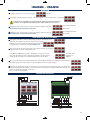
MEASUREMENT’S TYPOLOGY
True RMS up to the 20th harmonic wave
Crest factor up to 2,5
(Voltage and Current)
OPERATION: Instrument furnished already calibrated with the following data: Average = 3; default page = lost voltage; Current transformer = 25/5A;
Nominal voltage = 213V (ph-n) and 400V (ph-ph)
- When powered the device makes a self test (all segments of leds light-on for some seconds).
Changement of pages can be effected “FORWARD” by short pressure of right button, or “BACKWARD” by short pressure of left button.
Maintaining pressure on buttons you can have: fast forward, reset or configuration of parameters. When one of the button is pressed, the “title” of the page is shown.
- Measurements displaing
The measurements and signalling pages that appear (pushing and releasing the frontal button) are the following:
PUSHED BUTTON
RELEASED
DESCRIPTION
This FLASHING signal appears only if:
- this page is selected as “default page” (see the correspondent configuration chapter) and the instruments is just light-on or if the
auxiliary supply light-off and immediately light-on, or the parameters configuration is finished.
After the changement of this page, it disappears from the selection pages.
On the downer line the value of the voltage in Volt is displayed
medium voltage phase-phase
80
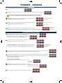
03 multifunzione GB 2011_digitali 24/05/11 14.28 Pagina 81
PUSHED BUTTON
RELEASED
DESCRIPTION
Measurement of voltage in Volt; the first upper led lights-on
If the small points, on the right, light-on (close to
each value of the voltage) it means that the
sequence of the phases is WRONG.
phase-phase voltages
Measurement of voltage in Volt; the central led lights-on
If the small points, on the right, light-on (close to
each value of the voltage) it means that the
sequence of the phases is WRONG.
phase-neutral voltages
On the downer line the value of asimmetry in Volt is displayed.
phase-phase voltage asimmetry
On the downer line the value of current in Ampere is displayed.
medium current
Values of current in Ampere. The bottom led lights-on
phase-phase currents
On the downer line the value of current in Ampere is displayed.
current on neutral
On the downer line the value of frequency in Hz is displayed.
frequency
Measurement of Actice Power in Watt.
The example shows 5775 W (5,775kW).
active power - phase 1
If on the right side of the value, a little point lightson it means that the value is NEGATIVE
active power - phase 2
active power - phase 3
Measurement of Actice Power in Watt.
The example shows 17325 W (17,325kW).
If on the right side of the value, a little point lightson it means that the value is NEGATIVE
total active power
81
03 multifunzione GB 2011_digitali 24/05/11 14.28 Pagina 82
PUSHED BUTTON
RELEASED
DESCRIPTION
Power factor (cosϕ). 4 quadrants value, between 0.00 and +/- 1.00.
If the displacement is POSITIVE (inductive) the indications on the display will be <ind> and a point on the
right lower side will be lights-off.
power factor - phase 1
If the displacement is NEGATIVE (capacitive) the indications on the
display will be <cap> and a point on the right lower side will be lights-on.
When the value is 1.00, the indication conventionally will be <ind>.
power factor - phase 2
power factor - phase 3
Power factor (cosϕ). 4 quadrants value, between 0.00 and
+/- 1.00.
If the displacement is POSITIVE (inductive) the indications
on the display will be <ind> and a point on the right lower
side will be lights-off.
If the displacement is NEGATIVE (capacitive)
the indications on the display will be <cap> and
a point on the right lower side will be lights-on.
When the value is 1.00, the indication conventionally will be <ind>.
total power factor
Measurement of Reactive Power in Var.
The example shows 954 var (0,954kvar).
reactive power - phase 1
If on the right side of the value, a little point lights-on it means
that the value is NEGATIVE, so the measured value is CAPACITIVE instead of INDUCTIVE.
reactive power - phase 2
reactive power - phase 3
Measurement of Reactive Power in Var.
The example shows 2862var (2,862kvar).
If on the right side of the value, a little point lights-on it
means that the value is NEGATIVE, so the measured
value is CAPACITIVE instead of INDUCTIVE.
total reactive power
Measurement of Apparent Power in VA.
The example shows 5775 VA (5,775kVA).
apparent power - phase 1
apparent power - phase 2
apparent power - phase 3
Measurement of Apparent Power in VA.
The example shows 17325 VA (17,325kVA).
total apparent power
82
03 multifunzione GB 2011_digitali 24/05/11 14.28 Pagina 83
PUSHED BUTTON
RELEASED
DESCRIPTION
Measurement of Energy in kWh.
The example shows 12521 KWh. When 999999 is displayed, counting start again from 0.
RESET:
By a long pressure of right button only, the value flashes, and after few seconds it will be resetted.
active energy (import)
Measurement of Energy in kWh.
The example shows 327 KWh. When 999999 is displayed, counting start again from 0.
RESET:
By a long pressure of right button only, the value flashes, and after few seconds it will be resetted.
active energy (export)
Measurement of Energy in kvarh.
The example shows 2543 kvarh. When 999999 is displayed, counting start again from 0.
RESET:
By a long pressure of right button only, the value flashes, and after few seconds it will be resetted.
reactive energy
Measurements of hours (h). It shows the total working time (from powering of instrument).
The example shows 37820 h. When 999999 is displayed, counting start again from 0.
total hourmeter
Measurements of hours (h). It shows the partial working time (from last reset of instrument).
The example shows 249 h. When 999999 is displayed, counting start again from 0.
RESET:
By a long pressure of right button only, the value flashes, and after few seconds it will be resetted.
partial hourmeter
PROGRAMMING: Make a long pressure (4 seconds about) on the RIGHT button, while you stay in a page where the resettable parameters are NOT
allowed. So not on the pages of Energy or Hour-counter otherwise you obtain the reset of these values without enter on the configuration pages.
The following page appears:
Where in the central line you’ll see the device type and release n°. Dot on upper right side of display flashes, three leds light-on meaning the configuration mode. This situation will remain until the end of procedure.
After 4 seconds the pages with configuration parameters start to be displayed; one page every 4 seconds showing the actual selected value.
If it is necessary to see the values without any modification don’t touch nothing until the automatic end of the showed pages.
To change the values of parameters, it is enough to press the RIGHT button while this parameter is displayed.
The value change immediately and closed to him a flashing points appear meaning that the value is in modification phase.
To fast forward maintain pressure on the RIGHT button.
The following can be made by pressing the left button:
- pressed during the automatic display of the pages, it increases the time you stay on this page until it is released.
- pressed during the setting of some value (when all the points on the right flashes) decrease step by step this value and it increases the time you stay on this page until
it is released.
The modified value is automatically saved in permanent way when the automatic display of the pages starts again.
The following pages can be present or not depending by the model of instruments.
DEFAULT PARAMETER POSSIBLE VALUES
VALUE
from 1 to 15
DESCRIPTION
It is the number (n) of single measures effected on the electrical parameter before it’s visualization on the display.
Practically it is the filter of the measure stabilization. The numbering rise up from 1 to 15; more higher is the selected number,
more slow are the eventual variations of reading. This is valid for all the measured parameters.
average
Select the main page that you want to see after the initial powering of the instrument.
ONE OF THE
AVAILABLE
PAGES
Default page
CT .../5A
VALUE
from 5 to 999
every 5
steps
VALUE
from
200 to 262
voltage setting
Select the ratio .../5A of the current transformer.
It represent the NOMINAL voltage value of end scale value.
Phase-phase voltage on the central line.
Phase-neutral voltage on the lower line.
The default value (calibrated in factory) is 231V (400V phase-phase).
83
03 multifunzione GB 2011_digitali 24/05/11 14.28 Pagina 84
THREE PHASE LED MULTIFUNCTION METERS
1RANM6....
2RAN96....
DIMENSIONS in mm
91 +0,8
58
91 +0,8
85
45
A = 97,3 without terminals cover
A = 116,5 with terminals cover
Weight: 0,55 kg
A
89
96
105
96
The 105 mm dimensions correspond to 6 DIN modules
TECHNICAL CHARACTERISTICS
MODULAR VERSION
SWITCHBOARD VERSION
1RANM6
2RAN96
1RANM6R
2RAN96R
1RANM6C
2RAN96C
1RANM6CS
2RAN96CS
•
•
•
•
•
•
•
•
•
•
•
•
•
•
•
•
•
•
•
•
•
•
•
•
•
•
•
•
•
•
•
•
1RANM6C485 1RANM6CS485 1RANM6C232
2RAN96C485 2RAN96CS485
ELECTRICAL PARAMETERS
- Phase-phase Voltage
- Phase-neutral Voltage
- Current
- Total Active Power
- Total Reactive Power
- Total Apparent Power
- Total Active Energy
- Partial Active Energy
- Total Reactive Energy
- Power Factor
- Frequency
- Phase sequence
- Partial and Total working hours
Possibility to use the output contacts by software
(for example: turn-on or turn-off an engine)
The software is available, free of charge, on our internet address www.revalco.it
STANDARD POWER SUPPLY
NOMINAL INPUT VALUES
Voltage
Primary current
Secondary current
Frequency
SELECTABLE CAPACITIES
PRECISION CLASS
CONSUMPTION
FRONT PROTECTION DEGREE
INSULATION CLASS
WORKING TEMPERATURE
STORAGE TEMPERATURE
TEST VOLTAGE
MEMORY
TWO OUTPUT REED RELAYS
NA (0,5A-1000V)
with high power (max 20VA),
switching voltage (1000VDC) or peak AC
SERIAL OUTPUT
PROTOCOL
INSULATION VOLTAGE
WEIGHT kg
84
•
•
•
•
•
•
•
•
•
•
•
•
•
•
•
•
•
•
•
•
•
•
•
•
•
•
•
•
•
•
•
•
•
•
•
•
•
•
•
•
•
•
•
230 VAC 50/60Hz
500V
from 5A to 6000A selectable by button located at the front
5A (1A on request)
from 40 to 60 Hz
from 5A to 1000A with steps of 5A – from 1000A to 6000A with steps of 50A
2% ± 2 digit (Power and Energy) 0,5% ± 2 digit (all other values)
4VA
IP20
II
-5°C ......... +50°C
-20°C ......... +70°C
2kV at 50Hz for 1 minute
EEPROM
NA (0,5A-1000V)
NA (0,5A-1000V)
RS485
MODBUS SLAVE RTU
3kV
0,50
RS232
MODBUS SLAVE RTU
ASCI on request
03 multifunzione GB 2011_digitali 24/05/11 14.28 Pagina 85
1RANM6 - 2RAN96
OPERATION
Powering the instrument you can see the following page
Main fault
By pressing the front button, the introduction page of this analyser appears, on which the actual version is also identified.
In this position, the configuration selection menu page will appear (see at the bottom of this page)
To enter into the configuration menu maintain pressure on the front button for a few seconds
three voltages phase/phase
Maintaining pressure on the front button you will see the parameters displayed on this page
Releasing the button the measurements will be shown
three currents
three voltages phase/neutral
Maintaining pressure on the front button you will see the parameters displayed on this page
Releasing the button the measurements will be shown
three currents
CONFIGURATION SELECTION MENU
By pressing the front button for a few seconds a flashing page appears, indicating that you are
entering into the configuration selection menu, and you will see for example:
Maintain pressure on the front button untill the following page is displayed.
Releasing the button the further pages will be automatically shown
After a few seconds the CT selection page appears, by pressing the front button you can select the
required CT value. From 5A up to 999A with steps of 5A
From 1000A up to 6000A with steps of 50A for their display it is necessary to refer in kA
values where this unit measurement is indicated by the illumination of the light located on
the extreme right of the display . To fast forward maintain pressure on the front button
The example shows
the displays of a
1200A CT
After a few seconds the page of the mathematical medium n° of samples appears; practically it is the stability filter of the measurement.
The numbering goes from 1 to 60; the higher is the selected number the slower is the change of displays.
Automatically the following page appears: here it is possible to select and memorise the main page that you want to see after the initial
energising of the instrument. By pressing in succession the front button, the various titles of the pages available appear and when you
see the one required release the button to memorise it.
After 5 seconds the next page appears.
CONNECTION DIAGRAMS
230V ~ 50 Hz
N
V
17
15
2
1
3
4
19
6
7
5A
S1
S2
S1
S2
S1
S2
P1
P2
P1
P2
P1
P2
8
230V 50Hz
13
N
L1
N
1RANM6
V
5A
N L
L1
L2
L3
L1
L2
L3
S1
S2
S1
S2
S1
S2
P1
P2
P1
P2
P1
P2
N
2RAN96
85
03 multifunzione GB 2011_digitali 24/05/11 14.28 Pagina 86
1RANM6R - 2RAN96R
OPERATION
Powering the instrument you can see the following page
Main fault
By pressing the front button, the introduction page of this analyser appears, on which the actual version is also identified.
In this position, the configuration selection menu page will appear (see at the bottom of this page)
To enter into the configuration menu maintain pressure on the front button for a few seconds
Maintaining pressure on the front button you will see the parameters displayed on this page
Releasing the button the measurements will be shown
three voltages phase/phase
three currents
Maintaining pressure on the front button you will see the parameters displayed on this page
Releasing the button the measurements will be shown
three voltages phase/neutral
three currents
Showing the actual
situation of
the thresholds
Maintaining pressure on the front button you will see the parameters displayed on this page
Releasing the button ,the activation(ON) or the deactivation(OFF) of the two thresholds (th1 and th2) appears
CONFIGURATION SELECTION MENU
By pressing the front button for a few seconds a flashing page appears, indicating that you are entering
into the configuration selection menu, and you will see for example:
Maintain pressure on the front button untill the following page is displayed.
Releasing the button further pages will be automatically shown
After a few seconds the CT selection page appears, by pressing the front button you can select
the required CT value. From 5A up to 999A with steps of 5A
From 1000A up to 6000A with steps of 50A for their display it is necessary to refer in kA
values where this unit measurement is indicated by the illumination of the light located on
the extreme right of the display . To fast forward maintain pressure on the front button
The example shows
the displays of a
1200A CT
After a few seconds the page of the mathematical medium n° of samples appears; practically it is the stability filter of the measurement.
The numbering goes from 1 to 60; the higher is the selected number the slower is the change of displays.
Automatically the following page appears: here it is possible to select and memorise the main page that you want to see after the initial
energising of the instrument. By pressing in succession the front button, the various titles of the pages available appear and when you
see the one required release the button to memorise it.
After 5 seconds the next page appears.
1st alarm threshold configuration page
When pressing the front button it is possible to choose between:
OFF,
Hi (max alarm),
Lo (min alarn)
On the further page it is possible to select the delay time of the 1st threshold
When pressing the front button it is possible to choose between:
OFF - On (excitation relay delay) or
On - OFF (disexcitation relay delay)
On the further page it is possible to select the delay time up to max 30 seconds
86
03 multifunzione GB 2011_digitali 24/05/11 14.28 Pagina 87
On the further page it is possible to select the parameter to which applies the 1st alarm threshold between:
3U alarm applied simultaneously to the three phase-neutral voltages, where is enough that one of the three voltages exceeds the selected value to activate the alarm
3UF alarm applied simultaneously to the three phase-phase voltages, where is enough that one of the three voltages exceeds the selected value to activate the alarm
3i
alarm applied simultaneously to the three currents, where is enough that one of the three currents exceeds the selected value to activate the alarm
i1
alarm applied to the L1 current phase
i2
alarm applied to the L2 current phase
i3
alarm applied to the L3 current phase
U1 alarm applied to the L1 phase-neutral voltage phase U2 alarm applied to the L2 phase-neutral voltage phase U3 alarm applied to the L3 phase-neutral voltage phase
U12 alarm applied to the L1-L2 voltage phase
U23 alarm applied to the L2-L3 voltage phase
U31 alarm applied to the L3-L1 voltage phase
The further page shows also the percentage value of the alarm.It is possible to modify the percentage value of the alarm;
by pressing the front button the percentage is varied with steps of 1%( to fast forward maintain pressure on the front button)
and displayed on the page is the equality between the numerical value and the percentage.
Example: having choosen the parameter 3UF, the percentage 51% correspond to 255V
Now the 2nd alarm threshold configuration page appears
Where it is necessary to act exactly as explained above
CONNECTION DIAGRAMS
Alarm 2
Alarm 2
V
N
13
17
15
3
4
19
6
7
5A
L1
L2
L3
S1
S2
S1
S2
S1
S2
P1
P2
P1
P2
P1
P2
N
L1
Alarm 1
21 22 23 24
8
230V 50Hz
2
1
0,5A - 100V NA
230V ~ 50 Hz
NA
Alarm 1
C
0,5A - 100V
C
N L
L1
L2
L3
N
1RANM6R
V
5A
S1
S2
S1
S2
S1
S2
P1
P2
P1
P2
P1
P2
N
2RAN96R
87
03 multifunzione GB 2011_digitali 24/05/11 14.28 Pagina 88
1RANM6C / 1RANM6C485 / 1RANM6C232
2RAN96C / 2RAN96C485
OPERATION
Powering the instrument you can see the following page
Main fault
By pressing the front button, the introduction page of this analyser appears
on which the actual version is also identified.
or
or
In this position, the configuration selection menu page will appear (see at the bottom of this page)
To enter into the configuration menu maintain pressure on the front button for a few seconds
three voltages phase/phase
Maintaining pressure on the front button you will see the parameters displayed on this page
Releasing the button the measurements will be shown
three currents
Maintaining pressure on the front button you will see the parameters displayed on this page
Releasing the button the measurements will be shown
three voltages phase/neutral
three currents
Maintaining pressure on the front button you will see the parameter displayed on this page
Releasing the button the measurement will be shown
Total Active Power,
expressed in Watt
Maintaining pressure on the front button you will see the parameter displayed on this page
Releasing the button the measurement will be shown
Total Reactive Power
expressed in Var
Maintaining pressure on the front button you will see the parameter displayed on this page
Releasing the button the measurement will be shown
Total Apparent Power,
expressed in VA
Maintaining pressure on the front button you will see the parameter displayed on this page
Releasing the button the measurement will be shown
Total Active Energy
expressed in kWh
Maintaining pressure on the front button you will see the parameter displayed on this page
showing the quantity of energy used in 15 min
Releasing the button the measurement will be shown
Relative Active Energy,
expressed in kWh,
memorised every 15 min.
The flashing symbol means that the instrument is counting the used energy during 15 minutes; when the symbol becomes static it means
that the 15 minutes are passed and the final value is shown. To zero this value, maintain pressure on the front button.
Maintaining pressure on the front button you will see the parameter displayed on this page
Releasing the button the measurement will be shown
Maintaining pressure on the front button you will see the parameters displayed on this page
Capacitive (
) or Inductive Power Factor (
) in number (
), or in electrical degrees (
Frequency from 30hz to 70Hz (
)
Releasing the button the measurement will be shown
Maintaining pressure on the front button you will see the
parameters displayed on this page
Total Reactive Energy
expressed in kVar
)
Phase sequence
Releasing the button this indication appears
or
(not correct sequence)
(correct sequence)
Maintaining pressure on the front button you will see the parameter displayed on this page
Hourmeter indicating the working hours of the instrument, the memorising of the time occurs every 15 min
Releasing the button the measurement will be shown
Maintaining pressure on the front button you will see the parameter displayed on this page
Releasing the button the measurement will be shown
Partial hourmeter indicating the working
hours of the instrument
(zeroing in the next page)
Maintaining pressure on the front button you will see
the parameters displayed on this page:
Releasing the button the measurement will be shown
Actual analogue bar of the Active Power respect to the Total Apparent Power
Actual analogue bar of the Reactive Power respect to the Total Apparent Power
This page serves to give an immediate visual display showing the situation of the installation
Releasing the button you can see for example at cosϕ1 the following display:
Active Power
Reactive Power
88
03 multifunzione GB 2011_digitali 24/05/11 14.28 Pagina 89
If the value of the cosphi goes down, the phase displacement angle is immediately displayed, and the Active
Power’s bar goes down while the Reactive Power’s bar will increase as for example in the figure:
Active Power
Reactive Power
Maintaining pressure on the front button you see the parameter displayed on this page
Visual simulation of the rotation of the electromechanical active kWh-meter indicating how much energy you are using at that time
Releasing the button the graphics will be shown
Maintaining pressure on the front button you see
the parameter displayed on this page
Releasing the button the graphics will be shown
Analogue display bar of the Active Power (settable)
If for example the selected CT is 50/5A but it is well known that the installation is already at 100% with 40A, You’ll set the instrument in the way that with 40A the
bar shows 100%
CONFIGURATION SELECTION MENU
By pressing the front button for few seconds a flashing page appears,
indicating that you are entering into the configuration selection menu,
and you will see for example:
or
or
Maintain pressure on the front button untill the following page is displayed.
Releasing the button the further pages will be automatically shown
After a few seconds the CT selection page appears, by pressing the front button you can select the required CT value.
From 5A up to 999A with steps of 5A
From 1000A up to 6000A with steps of 50A and for their display it is necessary to refer in kA
values where this unit measurement is indicated by the illumination of the light located on
the extreme right of the display . To fast forward maintain pressure on the front button
The example shows the displays of a 1200A CT
After a few seconds the page of the mathematical medium n° of samples appears; practically it is the stability filter of the measurement.
The numbering goes from 1 to 60; the higher is the selected number the slower is the change of displays.
After a few seconds the following page appears, on which it is possible to select the end scale value
of the analogue bar of the Active Power (Act Ratio). The indicated example shows a value of 92% that can
be modified (with steps of 1%) by pressing the front button(To fast forward maintain pressure on the front button)
Releasing the button the page will show also the numerical equality in Watt of the percentage choosen
In function of the nominal calibration data. If for example the CT 50/5A is selected and the percentage is 92% you’ll see:
where 6900W correspond to the end scale (92%)
calculated as follow: 92% = Vnom
x CT value x 3
230V ph/n
50/5A
230 x 50 = 11500
11.500 : 5 = 2300 2300 x 3 = 6900
(400V ph/ph)
Automatically the following page appears: here it is possible to select and memorise the main page that you want to see after the
initial energising of the instrument. . By pressing in succession the front button, the various titles of the pages available appear and when
you see the one required release the button to memorise it.
After 5 seconds the next page appears( version 1RANM6C485 only)
on which, by pressing the front button, it is possible to change the address to assign)
serial address
CONNECTION DIAGRAMS - For serial communication, see the proper pages
230V ~ 50 Hz
1RANM6C
N
L1
2RAN96C
V
5A
L1
L2
L3
S1
S2
S1
S2
S1
S2
P1
P2
P1
P2
P1
P2
N
A
B
A
B
2RAN96C485
1RANM6C485
1RANM6C232
89
03 multifunzione GB 2011_digitali 24/05/11 14.28 Pagina 90
1RANM6CS / 1RANM6CS485
2RAN96CS / 2RAN96CS485
OPERATION
Powering the instrument you can see the following page
Main fault
By pressing the front button, the introduction page of this analyser appears,
on which the actual version is also identified.
or
In this position, the configuration selection menu page will appear (see at the bottom of this page)
To enter into the configuration menu maintain pressure on the front button for a few seconds
three voltages phase/phase
Maintaining pressure on the front button you will see the parameters displayed on this page
Releasing the button the measurements will be shown
three currents
Maintaining pressure on the front button you will see the parameters displayed on this page
Releasing the button the measurements will be shown
three voltages phase/neutral
three currents
Maintaining pressure on the front button you will see the parameter displayed on this page
Releasing the button the measurement will be shown
Total Active Power,
expressed in Watt
Maintaining pressure on the front button you will see the parameter displayed on this page
Releasing the button the measurement will be shown
Total Reactive Power
expressed in Var
Maintaining pressure on the front button you will see the parameter displayed on this page
Releasing the button the measurement will be shown
Total Apparent Power,
expressed in VA
Maintaining pressure on the front button you will see the parameter displayed on this page
Releasing the button the measurement will be shown
Total Active Energy
expressed in kWh
Maintaining pressure on the front button you will see the parameter displayed on this page
showing the quantity of energy used in 15 min
Releasing the button the measurement will be shown
Relative Active Energy
expressed in kWh
memorised every 15 min.
The flashing symbol means that the instrument is counting the used energy during 15 minutes; when the symbol becomes static it means
that the 15 minutes are passed and the final value is shown. To zero this value, maintain pressure on the front button.
Maintaining pressure on the front button you will see the parameter displayed on this page
Releasing the button the measurement will be shown
Maintaining pressure on the front button you will see the parameters displayed on this page
Capacitive (
) or Inductive Power Factor (
) in number (
), or in electrical degrees (
Frequency from 30Hz to 70Hz (
)
Releasing the button the measurement will be shown
Maintaining pressure on the front button you will see the
parameter displayed on this page
Total Reactive Energy
expressed in kVar,
)
Phase sequence
Releasing the button this indication appears :
or
(not correct sequence)
(correct sequence)
Maintaining pressure on the front button you will see the parameter displayed on this page
Hourmeter indicating the working hours of the instrument, the memorising of the time occurs every 15 min
Releasing the button the measurement will be shown
Maintaining pressure on the front button you will see the parameter displayed on this page
Releasing the button the measurement will be shown
Partial hourmeter indicating the working
hours of the instrument
(zeroing in the next page)
Maintaining pressure on the front button you will see the
parameter displayed on this page
90
Actual situation of the thresholds
Releasing the button, the activation (ON) or the deactivation (OFF)
of the two thresholds (th1 and th2) appears showing
03 multifunzione GB 2011_digitali 24/05/11 14.28 Pagina 91
Maintaining pressure on the front button you see the
parameters displayed in this page
Releasing the button the measurement will be shown
Actual analogue bar of the Active Power respect to the Total Apparent Power
Actual analogue bar of the Reactive Power respect to the Total Apparent Power
This page serves to give an immediate visual situation of the installation
Releasing the button you can see for example at cosϕ1 the following display
Active Power
Reactive Power
If the value of the cosphi goes down, the phase displacement angle is immediately displayed, and the
Active Power’s bar goes down while the Reactive Power’s bar will increase as for example in the figure:
Active Power
Reactive Power
Maintaining pressure on the front button you see the parameter displayed on this page
Visual simulation of the rotation of the electromechanical active kWh-meter indicating how much energy you are using at that time
Releasing the button the graphics will be shown
Maintaining pressure on the front button you see
the parameter displayed on this page
Releasing the button the graphics will be shown
Analogue display bar of the Active Power (settable)
If for example the selected CT is 50/5A but it is well known that the installation is already at 100% with 40A,
You’ll set the instrument in the way that with 40A the bar shows 100%
CONFIGURATION SELECTION MENU
By pressing the front button for a few seconds a flashing page appears, indicating that you are entering
into the configuration selection menu, and you will see for example:
or
Maintain pressure on the front button untill the following page is displayed.
Releasing the button the further pages will be automatically shown
After a few seconds the CT selection page appears, by pressing the front button you can select the
required CT value. From 5A up to 999A with steps of 5A
From 1000A up to 6000A with steps of 50A and for their display it is necessary to refer in kA
values where this unit measurent is indicated by the illumination of the light located on the
extreme right of the display. To fast forward maintain pressure on the front button
The example shows
the display of
a 1200A CT
After a few seconds the page of the mathematically medium n° of samples appears; practically it is the stability filter of the measurement.
The numbering goes from 1 to 60; the higher is the selected number the slower is the change of displays.
After a few seconds the following page appears, on which it is possible to select the end scale value of the
analogue bar of the Active Power (Act Ratio). The indicated example shows a value of 92% that can be
modified (with steps of 1%) by pressing the front button
(To fast forward maintain pressure on the front button).
Releasing the button the page will show also the numerical equality in Watt of the percentage choosen
In function of the nominal calibration data. If for example the CT 50/5A is selected and the percentage is 92% you’ll see:
where 6900W correspond to the end scale (92%)
Calculated as follow: 92% = Vnom
x
CT value x 3
230V ph/n
50/5A
230 x 50 = 11500
11.500 : 5 = 2300 2300 x 3 = 6900
(400V ph/ph)
Automatically the following page appears: here it is possible to select and memorise the main page that you want to see after the initial
energising of the instrument. By pressing in succession the front button, the various titles of the pages available appear and
when you see the one required release the button to memorise it.
After 5 seconds the next page appears. (version 1RANM6CS485 only)
on which , by pressing the front button, it is possible to change the address to assign
1st alarm threshold configuration page
Where pressing the front button it is possible to choose between:
OFF
Hi (max alarm),
Lo (min alarn)
serial address
OFF,
On the further page it is possible to select the delay time of the 1st threshold
Where pressing the front button it is possible to choose between:
OFF - On (excitation relay delay) or
On - OFF (disexcitation relay delay)
On the further page it is possible to select the delay time up to max 30 seconds
91
03 multifunzione GB 2011_digitali 24/05/11 14.29 Pagina 92
On the further page it is possible to select the parameter to which apply the 1st alarm threshold between:
3U alarm applied simultaneously to the three phase-neutral voltages, where is enough that one of the three voltages exceeds the selected value to activate the alarm
3UF alarm applied simultaneously to the three phase-phase voltages, where is enough that one of the three voltages exceeds the selected value to activate the alarm
3i alarm applied simultaneously to the three currents, where is enough that one of the three currents exceeds the selected value to activate the alarm
i1 alarm applied to the L1 current phase
i2 alarm applied to the L2 current phase
i3 alarm applied to the L3 current phase
U1 alarm applied to the L1 phase-neutral voltage phase U2 alarm applied to the L2 phase-neutral voltage phase U3 alarm applied to the L3 phase-neutral voltage phase
Act alarm applied to the Active Power
rEA alarm applied to the Reactive Power
APP alarm applied to the Apparent Power
U12 alarm applied to the L1-L2 voltage phase
U23 alarm applied to the L2-L3 voltage phase
U31 alarm applied to the L3-L1 voltage phase
FrE alarm applied to the frequency
deg alarm applied to the electrical degrees of the Power factor
CoS alarm applied to the COSphi of the Power Factor
The further page shows also the percentage value of the alarm.It is possible to modify the percentage value of the alarm; by pressing
the front button the percentage is varied with steps of 1%( to fast forward maintain pressure on the front button) and displayed on the
page is the equality between the numerical value and the percentage. Example: having choosen the parameter 3UF, the percentage
51% correspond to 255V
Now the 2nd alarm threshold configuration page appears
Where it is necessary to act exactly as explained before
If in the configuration phase you decide NOT to use one or both threshold, these will remain available
to be controlled via MODBUS SLAVE RTU, by the controll software.
CONNECTION DIAGRAMS
Alarm 2
0,5A - 100V
C
230V ~ 50 Hz
NA
N
L1
Alarm 1
1RANM6CS
2RAN96CS
V
5A
L1
L2
L3
S1
S2
S1
S2
S1
S2
P1
P2
P1
P2
P1
P2
N
A
B
A
B
2RAN96CS485
1RANM6CS485
SERIAL COMMUNICATION
Scheme n. 1: Connection between instruments and PC for distances up to 800m
RS485
-
Max 800 m
+
+
2RAN96C485
2RAN96CS485
RS232
Max 15 m
-
1RANM6C485
1RANM6CS485
1RINT
RS485
Scheme n. 2: Connection via Modem
RS485
+
-
Max 800 m
Telephone Line
RS232
RS232
Max 15 m
Max 15 m
MODEM
+
2RAN96C485
2RAN96CS485
92
1RANM6C485
1RANM6CS485
RS485
1RINT
MODEM
03 multifunzione GB 2011_digitali 24/05/11 14.29 Pagina 93
LCD THREE-PHASE DIGITAL MULTIFUNCTION METER
WITH COMMAND FOR ANALOGUE MODULES - TRUE RMS
1RAEMCS485-UA
1RUA1
GENERAL DESCRIPTION
The 6 DIN modules instrument is suitable for use in industrial environments. Simple and compact, has an alphanumeric display with 2 lines / 16 characters each, and 3 buttons to select the display and programming keyboard. The simplicity of the customization operations and clarity of information on the display make it not necessary the use
of the instruction manual, which is very rarely available, especially in the field. This instrument is suitable for measures of AC voltages and currents only; internally in fact there
is the presence of 3 current tansformers which cannot permit the measures of DC components. The device correctly installed, supports (on the terminals) a maximum current of 6A and a maximum phase-neutral voltage of 290VAC. Input Voltages can be direct or through VTs.
Instrument has the programmability of both nominal value of the primary VT (85.....10000Vp) and secondary (.../100Vp or ... 400Vp).
In case of direct connection, the primary must be set at 400Vp (= 231Vn) and secondary at.... / 400Vp.
All voltage measurements have a resolution of 0,1 V. Input Currents can be direct( up to 5A, max 400Vp) or through CTs.
Instrument has the programmability of both nominal value of the primary CT (5.....6000A) and secondary (.../1A or .../5A).
In case of direct connection, the primary must be set at 5A and secondary a t.... /5A.
All current measurements have a resolution of 0,1 A. The range of “standard “ measures is available which is deemed useful to have in an industrial, high precision environment. The details concerning the Powers and Power Factor, are provided with a sign on four quadrants according to Annex E of the standard EN61268. The resolution for the
Powers is 1W -1VAR - 1VA
The accumulation of the energies, individually resettable (consumed, produced and reactive), can be useful where you have to plan interventions to the system and / or periodical checks of the lines operation, detect the consumption of the area, establish cost centers, etc.. etc..
The accumulation of energy has a resolution of 1kWh (1kvarh).
The instrument uses a simple aggregation of energies for diagnostic / statistics. In no way the instrument is to be considered a substitute of an energy
kW-hour meter.
Also available:
2 Hour-counters -Total hours reader (not resettable) and partial hours reader (resettable),
1 programmable Interface RS485 opto-insulated 3kV high speed , MODBUS RTU.protocol
1 high speed (max load 150mA ) interface for connection with analogue modules series 1RUA1 or equivalent
FEATURES SUMMARY
1RAEMCS485-UA
- Measure of 3 Phase/Phase voltages and 3 Phase/Neutral voltages
- Measure of threephase average voltage
- Measure of asymmetric Phase/Phase voltages
- Measure of 3 currents and average current
- Measure of Frequency
- Measure of 3 Active and Reactive Powers, 4 quadrants
- Measure of Total Active and Reactive Power, 4 quadrants
- Measure of 3 Apparent Powers and Total Apparent Power
- Measure of 3 lines Cosphi and Total Cosphi
- Totalization of consumed and produced Active Energy, resettable
- Totalization of Total Reactive Energy, resettable
- Total and partial working hours counter (Partial resettable)
- 2 programmable thresholds as alarm or as implusive outputs proportional to Active or Reactive energy - N.O. contact (0,5A/1000V-20VA)
-Summary page of the thresholds state
- Indication of correct voltage phase sequence
- Indication of power failure
- RS485 High-Speed Interface, 5 speed, 3KV opto-insulated
- MODBUS RTU and ASCII full-compliance protocol
- Programmable parameters from menu and keyboard
- Programmable parameters, Energy reset, Partial hours counter reset, Output relay commands (if threshold in OFF) in MODBUS way
- Programmable password for programm access
- Factory parameters reset function
- First page setting
- CT Primary current setting, from 5 A to 6000A, step 5A and VT Primary voltage setting, from 87V to 10000V
- CT Secondary current setting (.../1 A or ..../5 A ) and VT Secondary voltage setting, ( 400V or 100V)
- Analogue average setting (V, I and P)
- Bootloader firmware upgrade by RS485
Features controls for analog modules 1RUA1
- Up to 15 modules1 RUA individually managed 1RUA1
Parameters and control of each module
- Page display of module status
- Choosing of measuring source of each module between 18 possible quantities
- Setting of 4 points output: beginning scale measure-beginning analogue output scale / end scale measure-end scale analogue output
- PERMANENT MEMORY FOR SET POINT AND ENERGIES (EEPROM)
- DIMENSIONS
•
•
•
•
•
•
•
•
•
•
•
•
•
•
•
•
•
•
•
•
•
•
•
•
•
•
•
•
•
•
•
•
6 DIN modules
93
03 multifunzione GB 2011_digitali 24/05/11 14.29 Pagina 94
TECHNICAL CHARACTERISTICS
94
Environmental conditions
- Operating temperature
- Extreme range
- Storage temperature
- Relative humidity
- Atmospheric pressure
0...+45 °C
-5...+55 °C
-10...+70 °C
10...95 %
70...110 kPa
CEI Standards:
- Safety CEI EN 61010-1 300V CAT III
- Precision CEI EN 60688
- EMC (immunity) CEI EN 61000-6-2 (ex EN 50082-2)
- EMC (emission) CEI EN 61000-6-4 (ex EN 50081-2)
- IP Protection degree CEI EN 60529
- Powers and Cosφ measurement CEI EN 61268 All. “E” – EN 60375
Modbus:
- MODBUS APPLICATION PROTOCOL SPECIFICATION V1.1b, 28.12.2006.
SUMMARY POWERS DIAGRAM:
MEASUREMENT’S TYPOLOGY:
Crest factor
up to 2,5
(Voltage and
Current)
True RMS up
to the 20th
harmonic
wave
SERIAL INTERFACE
RS 485 galvanically insulated (3 kV), suitable for conventional net
COMMUNICATION DATA
MODBUS RTU Protocol
Address from 1 to 255
Selectable speed on “485” (bps) version: 9600, 19200, 38400, 57600, 115200
Selectable speed on “BT” (bps) version:
standard 115200; on request 9600, 19200, 38400, 57600
Parity: N; Bits: 8; Stop Bit: 1
The MODBUS registers table of instrument is available on request or on the
web site.
CONNECTION DIAGRAM
mA
V
C
-
3 4
5
6
7
1
LOAD
Power Supply
90...260VAC/DC
2
MAX 150mA
MODBUS
RX / TX
ser
BUS command
15 anal modules
RS485
B
A
19 20
1
25
2
27
4 5
9
P1
P2
P1
P2
P1
P2
S1
S2
S1
S2
S1
S2
29 30 31 32 33 34 35 36
12
15
18
V
Alarm / Imp 1
Auxiliary Power Supply
- Nominal voltage (Vaux)
90…250 VAC or VDC
- Maximum Power Consumption
2 VA
Voltage circuit (Instrument for direct insertion)
- Maximum permissible voltage (Vmax)
290V Ph/N(500V Ph/Ph)
- Nominal voltage of measure (Vnom)
400 V Ph/Ph (231V Ph/N)
- Measuring direct range 0-290V Ph/N (500Vff) TRMS up to 20th harmonic wave
- Input impedance
≈ 2MΩ Ph/N and Ph/Ph
- VT range
=Vnom
- Class
0.5%*Vmax ± 2 digit
Voltage circuit (Instrument for insertion by VT... /100V)
- Maximum permissible voltage (Vmax)
75V Ph/N (130V Ph/Ph)
- Nominal voltage of measure (Vnom)
57,75V Ph/N (100V Ph/Ph)
- Measuring direct range 0-75V Ph/N (130V Ph/Ph) TRMS up to 20th harmonic wave
- Input impedance
≈ 500KΩ Ph/N and Ph/Ph
- VT range (primary)
86,5…10000V Ph/Ph (50…5774V Ph/N)
- Class
0.5%*Vmax ± 2 digit
Compatible Voltage transformers
- Nominal voltage (secondary)
.../100 V or .../400V
Current circuits for CT .../5A
- Maximum permissible current (Imax)
6A
- Nominal current of measure (Inom)
5A
- Direct measuring range
0.03...6A
- Input impedance
≈ 20mΩ ± 1%
- Permanent overload
110% (Inom)
- Thermal overload (1 s)
200% (Inom)
- CT range (primary)
5…6000A with steps of 5A
- Class
0.5%*Imax ± 2 digit
Compatible Current transformers
- Nominal current (secondary)
...../5 A or ...... /1A
Frequency
- Frequency range
19.50...100.00Hz
- Operation range (V1)
35 – 290V Ph/N
- Class
0.05% ± 1 digit
Lines Power
- Measurement for each line
±54MW /±54Mvar /54MVA
- Class (0.05 > Inom > 1.0)
1 % f.s ± 2 digit
Total Powers
- Measurement
±162MW /±162Mvar /162MVA
- Class (0.05 > Inom > 1.0)
1 % f.s ± 2 digit
Power Factor (all)
- Measuring range cosφ
-1.00…0.00…+1.00
- Class (0.1 > Inom > 1.0, 0.8 > Vnom >1.2)
2% fs ± 2 digit
Energy totalization
- Counting capacity
999999999kWh /kvarh
- Counting period
15 min.
- Reset possibility
YES
- Class (0.05 > Inom > 1.0)
2% Max
Total Hours counter
- Counting capacity
999999:59 hhhhhh:mm
- Counting period
15 min.
- Reset possibility
NO
- Class
2% Max
Partial Hours counter
- Counting capacity
999999:59 hhhhhh:mm
- Counting period
15 min.
- Reset possibility
YES
- Class
2% Max
Display
- LCD back illuminated, 16 characters x 2 lines, temp. -20°/+70°.
Outputs relays
- Type of contact
N. O.
- Contact
1000VAC / 0,5 A AC(residual load) / 20VA max.
- Insulation coil- contact
4.25kVAC
- Remote operation by MODBUS
YES (programmable)
Serial RS485 interface
- Insulation
3kV
- Max speed communication
115.200 bps
- Communication protocol
MODBUS RTU Full-compliant / JBUS
- Remote Programmability and commands
YES
Special functions
- Securing access to the programming parameters by a 3-digit password
- Black-out indicator system
Mechanical Characteristics
- Dimensions
Standard 4 DIN modules
- Mounting type
DIN50022
- Protection degree
IP20/ Frontal IP30
Alarm / Imp 2
NO
N
L1 L2 L3
N
L3
L2
L1
03 multifunzione GB 2011_digitali 24/05/11 14.29 Pagina 95
FUNCTIONS
The instrument measures in real time the electrical parameters of the system to which it is connected, and it is able to show them on a page of measure, selectable by
short pressures on the keys, down pressures to "forward" and up pressure to go "back ". The first page to be displayed on the front is programmable
The instrument has two independent thresholds, allowing you to set for each threshold the parameter you wish to control; the type of threshold (off, maximum or ), the
threshold value (1/1000 of the full scale of the controlled parameter), the application of any delay on energization or de-energization and the delay time in decimal seconds
up to 25.5 Sec (0 = no delay).
Please refer to "Programming Keyboard Standard parameters" for details on the values of programming and the "Operation of programmable thresholds.
The instrument can be plugged into an RS485 network of instruments that communicates with MODBUS RTU or MODBUS ASCII. For reliability of communication, you
should use all the tricks in implementing network RS485 (polarizations, termination, etc. ..) especially when using many devices each ring and the distances are
considerable (hundreds of meters). Please note that any converters to be used must have highand proven quality to maximize the features of the network instruments
The communication speed is programmable between 9600bps and 115.200bps. Where in the ring are present only these instruments, we strongly recommend to use the
fastest communication. If the speed is too low and the demands are very frequent and / or the number of registers required is high, it can get slow interactions with the
instrument. All measurements and parameters are available simultaneously on read command MODBUS RTU or MODBUS ASCII. You do not need any selection protocol
because the instrument automatically adjusts the response to the application format.
Please note that by its nature, the ASCII communication is slower than the RTU, given the greater consistency of telegrams.
The instrument also provides the setting “on the fly” by remote control of the operating parameters via MODBUS write command to its registers which allow it.
It is permitted, under certain conditions, to perform some major-operations and commands, such as restoring factory settings on models which support it, the reset of the
counters, the direct control of on / off output relays for models with a threshold etc. etc.. For details of the MODBUS communication, refer to the relevant section below.
The instrument also automatically accepts a program in “menù” way that allows you to instantly configure a large number of parameters and quickly set up many
instruments to be all equal. Refer to the appropriate section of this manual. A page of black-out report is present
It 's a page like the measuring but with flashing content, which must be programmed as the first to be shown when the device is lights-on. When you act on the keys to
change the measurements page, the “black-out “condition is cleared which also reappears at the end of any programming parameters from the keyboard.
The instrument has 2 hour counters ; one for the total operating time (life of the instrument) and the second resettable useful to take into account for example,the
average consumption, if cleared, together with one or more counters of energy. It is provided that the change of operating parameters and the reset of the counters are
protected by a 3 digits password (disabled) This password is not oriented to a total protection, but only to prevent accidental access to the programming and the subsequent
alteration of the parameters unwanted by unauthorized personnel. The password, when present, protects the remote functionality of programming and command.
If the password is set and then forgotten, there is a quick way to recover or delete it. You will need to scan any combination, or resend the product to the factory for
reprogramming. The display section of the situation of 15 analog outputs managed, which can be accessed with a short press on "Enter" button, permits to control the
output values of analogue modules eventually connected. Keep in mind that: The voltage and current values shown (inter-related, not independent) are the ones who the
instrument send as implementation and not the effective present on the output of the relative module. If the relative module is absent or on failure, the instrument not
diagnostic it and continues to behave as if it is present. There is no feedback between instrument and connected modules on the output bus.
More analog modules connected to the bus output can have the same address. It means that if for example there are 5 modules with address 2, they will behave in an
identical manner in accordance with the planning for the module number 2 and their progress will be visible on the display page of module 2.
OPERATION
When switched-on the info firmware page appears for 2 seconds:
Immediately after, the selected measuring page will be presented with the parameter “Default Page”. If the first page is
the “black-out” , the following flashing message will appear:
14.04.11
01.15.01
PowerOn
Ready
Date (dd-mm-yy)
FW version (mod-rev)
The display (flashing) occurs only once after power-on or when this
page is selected as the start page and exit the programming of standard parameters. When you press a button it disappears from the
selection of display pages
When the first measurement page appears, you can immediately start to work with the keys to scroll through the available pages. The sliding may be “forward” with
short press on the DOWN button or “BACK” with the UP button.
The prolonged duration of pressure on “down” button causes, as well as the advancement of the page, also the entrance into the programming of the
“standard” parameters of the instrument.
To see the status of analogue modules, is sufficient that starting from the vision of the standard measures, you briefly press the” Enter” key. The correspondent
page to the currently selected module, appears (e.g. 1):
PRESSED BUTTON
RELEASED BUTTON
DESCRIPTION
Analog
Output01
An01(Act) 87.0%
I17.40 V08.70
Percentage value of considered measurement
Real value on the module output. mA and V
To see the pages related to the other outputs, press “DOWN “ to go on (02,03, ...) or “UP” to go back (15:14, ...).
On the first line appears:
Number of the module AnXX and in parenthesis the name of the represented parameter (i.e. Act = Active Power)
Percentage value of the instantaneous measurement with mark (from 100,0% to -100.0%)
On the second line appears:
Instantaneous forecasted values to the outputs of the correspondent module, current (mA) and voltage (V).
The values of voltage and current are not independent but related between them (1 mA = 0.5 V)
To return to the standard measurement display , simply press SHORTLY the “ENTER” key. Releasing it you go back to the standard measurement previously selected.
The prolonged duration of pressure on the “Enter” key, causes the entry to the programming of the parameters of analog modules connected to the
instrument
DISPLAY OF STANDARD MEASURES
The measurement and reporting pages which appear by briefly pressing and releasing in succession the “DOWN” button, as example may be as follows:
PRESSED BUTTON
RELEASED BUTTON
RAEM UA CS >>
485 : 001
RAEM UA CS >>
485 : 001
DESCRIPTION
Instrument name – Options – SQZ
MODBUS Node number
The view is the same if button is pressed or released
95
03 multifunzione GB 2011_digitali 24/05/11 14.29 Pagina 96
PRESSED BUTTON
RELEASED BUTTON
Vavg(V) 2 P (kW)
Iavg(A) Pf(tot)
V=400.0 2 P=69.3
I=100.0 Pf-0.99I
In(A) DVp(V)
Fre(Hz)
In 0.0 DV 0.0
F=50.00
Three-phase average voltage (V) – Three-phase Active Power (kW)
Three-phase average Current (A) – Power factor
Current in Neutral wire – Asymmetry Vp
Frequency (Hz)
Vp(V)
V23
V12
V31
Vp(V) 1=400.0
2=400.0 3=400.0
Voltage V1/V2
Vn(V)
V2
V1
V3
Vn(V) 1=231.0
2=231.0 3=231.0
Voltage V1
I(A)
I2
I1
I3
I(A) 1=100
2=100.0 3=100.0
Current Iine 1
PfLine Pf1
Pf2
Pf3
PfLine 1=-0.99I
2=-0.99I 3=-0.99I
Power Factor line 1
L1 Act Power
L1 Act Power
W
23100.0
Active Power line 1 (Title)
L2 Act Power
W
23100.0
Active Power line 2 (Title)
L3 Act Power
W
23100.0
Active Power line 3 (Title)
Total Act Power
W
69300.0
Total Active Power (Title)
L2 Act Power
L3 Act Power
Total Act Power
L1 Rea Power
L2 Rea Power
L3 Rea Power
Total Rea Power
L1 App Power
L2 App Power
L3 App Power
Total App Power
96
DESCRIPTION
Voltage V2/V3 – Voltage V3/V1
Voltage V2 – Voltage V3
Current Iine 2 – Current ine 3
Power Factor line 2 – Power Factor line 3
Active Power line 1 (Value)
Active Power line 2 (Value)
Active Power line 3 (Value)
Total Active Power (Value)
L1 Rea Power
var 0.0
Reactive Power line 1 (Title)
L2 Rea Power
var 0.0
Reactive Power line 2 (Title)
L3 Rea Power
var 0.0
Reactive Power line 3 (Title)
Total Rea Power
var 69300.0
Total Reactive Power (Title)
L1 App Power
VA 23100.0
Apparent Power line 1 (Title)
L2 App Power
VA 23100.0
Apparent Power line 2 (Title)
L3 App Power
VA 23100.0
Apparent Power line 3 (Title)
Total App Power
VA 69300.0
Total Apparent Power (Title)
Reactive Power line 1 (Value)
Reactive Power line 2 (Value)
Reactive Power line 3 (Value)
Total Reactive Power (Value)
Apparent Power line 1 (Value)
Apparent Power line 2 (Value)
Apparent Power line 3 (Value)
Total Apparent Power (Value)
03 multifunzione GB 2011_digitali 24/05/11 14.29 Pagina 97
PRESSED BUTTON
RELEASED BUTTON
Total Act Ene(+)
Total Act Ene(+)
kWh 999999999
Total Active Energy Buyed [+] (Title)
Total Act Ene(-)
kWh
0
Total Active Energy Selled [-] (Title)
Total Act Ene(-)
Total Rea Ene
Total Rea Ene
kvarh
0
Total Time
Total Time hh:mm
999999:59
Relative Time
Rel Time hh:mm
999999:59
Relais Outputs
Relais1 (W+)=ON
Relais2 (V12)=OFF
DESCRIPTION
Total Active Energy Buyed [+] (Value)
Total Active Energy Selled [-] (Value)
Total Reactive Energy (Title)
Total Reactive Energy (Value)
Total hours-counter (Title)
Total hours-counter (Value)
Partial hours-counter (Title)
Partial hours-counter (Value)
Relay outputs (Title) / Status Relay 1
Status relay 2
SPECIAL INDICATIONS ON THE DISPLAY
These indications relate solely to the display and not the values detected by the remote, which remain unchanged
Numerical values out of the scale
It may happen that some areas of the display don’t permit the representation of the numerical value due to the limited space available. In this case the digits are replaced
with the characters "^ ".
Measurement values out of scale
If the device detects a signal of excessive measure, the value of the parameter flashes (voltage or current) associated to its measurement. In the presence of such
information is necessary to verify that you are not exceeding the maximum input signal for the instrument, it can be damage.
This condition can be detected remotely on specific registers.
Indications related to the Power Factor (Pf)
In absence of its apparent power (VA = 0), the indication of the Power Factor is displayed with small lines “-,--“ and quadrant “I” or “C” disappear.
However from remote the survey is continuous and may not be significant.
In addition, the sign of the Power Factor from remote, must be taken from its relative Active Power and from relative indicator in the appropriate register for the quadrant
PROGRAMMING FROM KEYBOARD OF “STANDARD” PARAMETERS
To enter in programming phase , press and hold the DOWN button (more than 4 seconds)
When the input request is recognized, the confirmation page appears at the entrance of the programming.
Releasing the button, the display flashes (indicates that you are in programming phase)
If the "Password" is enabled (different from 000), the password request page appears, if not chosen correctly with the UP and DOWN buttons, let you exit from
programming mode after few seconds, returning to the standard display mode.
Otherwise, the programming pages begin to flow slowly ( one every 4 sec. about) showing the title and the current setting. If you do not touch UP or DOWN at the end
of the last page, the meter returns to normal display without any physical changes.
During this scrolling (but not during a modification), speeding up the return to standard mode, simply press the ENTER button briefly
To make changes, simply press a key when you see the desired page, respectively: UP key = increases the value and DOWN key = decrease the value.
At that point (when the button is pressed), the display is stable for easy reading and setting; the value advances unit by unit
For values far from the needed, you can use the fast forward by holding down the button for more than 2 seconds.
The longer it stays down and more scroll speed increse (4 speeds).
All values are 'roll' type; once reached the maximum value allowed them restart from the minimum and vice-versa.
When the value is correct, simply release the button for more than 4 seconds, so the scrolling of pages restart and the modified value is automatically stored
[1]
Programming entry
Program
Mode
[1]
Password Input. Appears only if "CHANGE PASSWORD" has been modified and is different from 000. If you do not respond to the
request with the correct value, you return to normal viewing of the measures.
[1]
Default parameters. Back to factory settings (except the hours and energy counters, if present).
Enter Password
000
Default
Parameters
It appears only if the instrument has been calibrated also for use of current transformation ratio ... / 1A.
Secondary adjustment: .../ 5A= 0 or .../1 A=1. Default = .../5A
Nominal value of primary CT, in steps of 5A. Represents the displayed value of current when on the input terminals is present the
nominal value of secondary current. Primary adjustment from 5 to 6000. Default = 100
From remote, the value in reading / writing must be considered with one decimal (Default = 100.0A)
CT Current Ratio
/5A
A
CT Set
100
97
03 multifunzione GB 2011_digitali 24/05/11 14.29 Pagina 98
It appears only if the instrument has been calibrated also for use of voltage transformation ratio ... /100V
Secondary adjustment : .../400V=0 or .../100V=1 Default = .../400V
In direct connection the value must be set to the phase/phase nominal voltage. During the adjustment,
above the Vp value, the equivalent Vn (phase/neutral) value appear. Adjustment from 86 to 10000Vp.
Default = 400Vp (231Vn). From remote, the value in reading / writing is the phase/neutral value,
in Modbus and menu’ mode with one decimal (Default=231.0 Vn).
Average analogue measurements (V, I and P).
Number of readings on which the measurement is made. More it is
large and more the updating measures is slow.
Adjustment from 1 to 15. Default = 3
VT Voltage Ratio
/400V
VT Set
Vp
400
Vn
Vp
COVER
231
400
PRESSED BUTTON (adjustment)
Average
3
Default Page
0
Page displayed when instrument is powered. Number of page which must be displayed when the instrument is turned-on. Please
refer to the numbers of pages. Adjustment from 0 to the number of the last page. Default = 0 (black-out
Set / Change Password. Numbers from 000 to 999 to block the access to the programming of parameters. With 000 (Default numbers) it is inactive, so the password request don’t appear and any
request by remote are permitted. Default = 0 (off)
[2]
Change Password
0
COVER
PRESSED BUTTON (> 4 sec)
DESCRIPTION
Act Ene(+) Reset
kWh
1523
Act Ene(+) Reset
kWh
0
[1] Reset consumed Energy (+). Press and hold the DOWN button (> 4 sec) to perform the reset.
During the pressure, the display stops flashing and just keeps flashing the message "Reset ".
When the value goes to zero, release the button
Act Ene(-) Reset
kWh
871
Act Ene(-) Reset
kWh
0
[1] Reset produced Energy (-). Press and hold the DOWN button (> 4 sec) to perform the reset.
During the pressure, the display stops flashing and just keeps flashing the message "Reset ".
When the value goes to zero, release the button
Rea Ene Reset
kvarh 203
Rea Ene Reset
kvarh
0
[1] Reset Reactive Energy. Press and hold the DOWN button (> 4 sec) to perform the reset.
During the pressure, the display stops flashing and just keeps flashing the message "Reset ".
When the value goes to zero, release the button
Rel Time Reset
1854:03
Rel Time Reset
0:00
[1] Reset Partial hours-counter. Press and hold the DOWN button (> 4 sec) to perform the reset.
During the pressure, the display stops flashing and just keeps flashing the message "Reset ".
When the value goes to zero, release the button
Selection of a Threshold 1 function. Adjustable between: Hi = Maximum Threshold (1), Lo = Minimum Threshold (2)
Off= Threshold off (0). If the threshold is Off, the following pages relate to it WILL BE NOT PRESENT. Default = Hi (maximum).
Th1 Sel
Hi
Th1 Dly
0.1
This page is present only if Th1 Sel is different from Off. Value of delay time of output relay,
expressed in seconds. Adjustable between 0.0 and 25.5 in steps of 0,1. Default = 0.1
This page is present only if Th1 Sel is different from Off. Assignment of delay time of output relay.
The delay time is applicable at the beginning of the intervention condition of the threshold (Off-On, 0), or to the end (On-Off, 1).
Default = Off-On (beginning)
Th1 Src
W+
This page is present only if Th1 Sel is different from Off. Assignment of parameter to which the threshold acts. Selectable between: 3Vp, V12, V23, V31,DVp, 3Vn, V1, V2, V3, 3I, I1, I2, I3, In, W+,
W-, Hz. Default = W+
This page is present only if Th1 Sel is different from Off. Adjustment of threshold value as a percentage of full scale, adjustable between 0.0% and 120.0%. During the adjustment, on the second line
above the percentage value, the equivalent value appears. Default = 50.0%
Th1 DD
Off-On
Th1 Val%
W+
50.0%
W+
COVER
Selection of a Threshold 2 function. Adjustable between: Hi = Maximum Threshold (1),
Lo = Minimum Threshold (2), Off= Threshold off (0). If the threshold is Off, the following pages relate to it WILL BE NOT PRESENT.
Default = Hi (maximum).
PRESSED BUTTON (adjustment)
Th2 Sel
Th2 Dly
0.1
This page is present only if Th2 Sel is different from Off. Value of delay time of output relay,
expressed in seconds. Adjustable between 0.0 and 25.5 in steps of 0,1. Default = 0.1
Hi
Th2 DD
Off-On
This page is present only if Th2 Sel is different from Off. Assignment of delay time of output relay. The delay time is applicable at the
beginning of the intervention condition of the threshold (Off-On, 0), or to the end (On-Off, 1). Default = Off-On (beginning)
This page is present only if Th2 Sel is different from Off. Assignment of parameter to which the
threshold acts. Selectable between: 3Vp, V12, V23, V31,DVp, 3Vn, V1, V2, V3, 3I, I1, I2, I3, In,
W+, W-, Hz. Default = W+
Th2 Src
W+
This page is present only if Th2 Sel is different from Off. Adjustment of threshold value as a
percentage of full scale, adjustable between 0.0% and 120.0%. During the adjustment, on the second
line above the percentage value, the equivalent value appears. Default = 50.0%
W+
Th2 Val%
50.0%
W+
COVER
NOTE [1]: The parameter is not accessible in menu’.
NOTE [2]: Parameter “Write-Only” from remote (not readable in serial way).
98
[1]
34650.0
50.0%
PRESSED BUTTON (adjustment)
MODBUS node number (and ID in menu’ way). It is the identification number of the instrument for serial communications of
various instruments in series. Adjustment from 1 to 255. Default = 1
Serial port speed. The type of interface changes depending on the model. The meaning of values
from 0 to 4 is: 0 = 9600 1 = 19200 2 = 38400 3 = 57600, 4 = 115 200 bps. Default = 4
34650.0
50.0%
[1]
Node
1
Speed
4
03 multifunzione GB 2011_digitali 24/05/11 14.29 Pagina 99
PROGRAMMING OF THE PARAMETERS FROM THE KEYBOARD OF ANALOGUE MODULES
To enter into the programming of the parameters of one of the 15 modules, select its page, then press and hold the ENTER key (more than 4 sec).
The following behavior is similar to the described for the programming of “standard” parameters, however, we repeat it for clarity.
When the request to enter in programming is recognized, the confirmation page appears at the entrance of the programming.
Releasing the button, the display flashes (indicates that you are in programming phase). If the “Password” is enabled (different from 000), the password request page
appears, if not chosen correctly with the UP and DOWN buttons, let you exit from programming mode after few seconds, returning to the standard display mode.
Otherwise, the programming pages begin to flow slowly (one every 4 sec. about) showing the title and the current setting. If you do not touch UP or DOWN at the end
of the last page, the meter returns to normal display without any physical changes. During this scrolling (but not during a modification), speeding up the return to standard
mode, simply press the ENTER button briefly. To make changes, simply press a key when you see the desired page, respectively: UP key = increases the value and
DOWN key = decrease the value. At that point (when the button is pressed), the display is stable for easy reading and setting; the value advances unit by unit
For values far from the needed, you can use the fast forward by holding down the button for more than 2 seconds.
The longer it stays down and more scroll speed increase (4 speeds). All values are ‘roll’ type; once reached the maximum value allowed them restart from the minimum
and vice-versa. When the value is correct, simply release the button for more than 4 seconds, so the scrolling of pages restart and the modified value is automatically stored. Displayed pages for ONE module only, as example ( equal for every other module)
Access to programming of parameters for ONE module (eg 01). Press and hold the ENTER
button (> 4 sec) to enter. When the right-hand page appears, release the button.
It starts flashing, then start the programming sequence
Analog
Output 01
Analog Output 01
Program Mode
PRESSED BUTTON (< 4 sec)
PRESSED BUTTON (> 4 sec)
Password Input. Appears only if “CHANGE PASSWORD” has been modified and is different from 000.
If you do not respond to the request with the correct value, you return to normal viewing of the module status.
Selection of measurement source for the analogue output
Sources Available: OFF, Vpa, V12, V23, V31, V1, V2, V3, Ia, I1, I2, I3, In, Act, Rea, App, PF, Hz,
Default = OFF
Enter Password
000
An01 Select SRC
(OFF)
COVER
PRESSED BUTTON (adjustment)
DESCRIPTION
An01 SRC MinVal
(Act) 0.0%
An01 34650.0
(Act)Min 50.0%
This page is present only if SRC Sel. is different from OFF
Minimum % value of the parameter pointed by SRC.
Range: depending on SRC, from 0.0% to 100.0%, or from -100.0% to 100.0%. Default = 0%
An01 OUT MinVal
I 0.00 V 0.00
An01 V 0.00
OUTMin I 0.00
This page is present only if SRC Sel is different from OFF
Minimum value at the output of “SRC MinVal”
Range: + / - 20.00mA, with steps of 0.01mA (= +/- 10.00V with steps of 0.005V). Default = 0.00mA (0.00V)
An01 SRC MaxVal
(Act) 100.0%
An01 69300.0
(Act)Max 100.0%
This page is present only if SRC Sel. is different from OFF
Maximum % value of the parameter pointed by SRC
Range: depending on SRC, from 0.0% to 100.0%, or from -100.0% to 100.0%. Default = 100%
An01 OUT MaxVal
I 20.00 V 10.00
An01 V 10.00
OUTMax I 20.00
This page is present only if SRC Sel is different from OFF.
Maximum value at the output of “SRC MaxVal”
Range: + / - 20.00mA, with steps of 0.01mA (= +/- 10.00V with steps of 0.005V).
Default = 20.00mA (10.00V)
To calculate the absolute number of parameter: Standard Parameters number+1+ [(Module number -1) x5 ]+ Relative number of parameter
OPERATION OF THE ANALOGUE CONTROL MODULES
The instrument, through the control bus, sends in sequence the command codes to each module in cyclical way. The commands are write-only, and are in any case sent
f whether the modules are connected or not and their reference source (SRC) is set to OFF. The command sent to a module whose source of reference is OFF, forces
the outputs to electrical zero (0mA - 0V). This ensures uniformity of the update times of the modules, regardless the increase or decrease of their number. The typical
time to update the full potential block of 15 units is 750 msec. It is provided that the modules must operate near the instrument and that the bus does not exceed the length
of several meters. However, if the modules must be removed and / or communication is infrequent / difficult, it may be necessary to use a line termination resistor with
value between 120 and 470 Ohm, to connect in parallel to the 2 wires . Please note that the bus is not protected from short –circuits and that it is planned for the maximum load of 15 units plus the eventual termination resistance. Do not apply more loads or different loads than the required. Let’s describe how to use the modules:
Each module can have a valid address from 1 to 15 (with zero, it not answer and goes to electrical zero). More modules can have the same address.
Their outputs will have identical behavior in response to the command to them address. The outputs of the modules are bidirectional (positive and negative) and related
to each other, then not independent. The value at terminals is: 1 mA = 0.5 V. The comfort is to have available on terminal V or I, with the same reference, the simultaneous parameters which can also be used simultaneously. The operating range of the outputs is between -20 and +20 mA to the terminal “I“ and as consequence, -10
and +10 V to terminal “V.” The values of out scale can reach 8-9% above the nominal full scale.
The measures that are converted by the instrument for the control of analogue modules, and programmed on the relative parameters 'SRC' are the following:
Parameter
Forecasted
N. choice
Full Scale
(Select SRC) (= 100.0%)
Description
N.
0
1
2
3
4
5
6
7
8
9
Code sending for outputs with electrical zero
Average of phase/phase voltage
V12
V23
V31
Voltage asymmetry (f/f)
V1
V2
V3
Average Current
10
11
12
13
14
15
16
17
18
OFF
Vpa
V12
V23
V31
DVp
V1
V2
V3
Ia
0
VT Set (value f/f)
VT Set (value f/f)
VT Set (value f/f)
VT Set (value f/f)
VT Set (value f/f)
VT Set (value f/n)
VT Set (value f/n)
VT Set (value f/n)
CT Set
Parameter
Forecasted
choice
Full Scal
(Select SRC) (= 100.0%)
I1
I2
I3
In
Act
Rea
App
Pf
Hz
CT Set
CT Set
CT Set
CT Set
CT Set * VT Set(f/n) *3
CT Set * VT Set(f/n) *3
CT Set * VT Set(f/n) *3
1.00
100.00Hz
Description
I1
I2
I3
Current in Neutral
Three-phase Active Power (with mark)
Three-phase Reactive Power (with mark)
Three-phase Apparent Power
Power Factor (with mark)
Frequency (measured on V1 line)
99
03 multifunzione GB 2011_digitali 24/05/11 14.29 Pagina 100
Choose the parameter in SRC, you then choose his minimum percentage value (SRC MinVal) to which correspond an output value OUT MinVal expressed in mA with
corresponding Volt. Same thing for the maximum value of the parameter (MaxVal SRC) to which the value OUT MaxVal will be associated
The calculation of current value to the analogue output is the following:
Hence knowing that 1mA = 0.5 V: Vout = Iout value / 2
If ,for any reason, the transmission of the value to the respective
module stops, after 2 seconds about of non-communication, it carry the outputs to electric zero .
OPERATION OF PROGRAMMABLE THRESHOLDS
The instrument l can apply two independent thresholds, maximum or minimum to the value, as percentage of a chosen parameter,, compared to its expected full scale.
Parameter
N. choice
(Th1 Src
/ Th2 Src)
0 3Vp
Forecasted
Full Scale
(= 100.0%)
VT Set (value f/f)
1
2
3
4
V12
V23
V31
DVp
VT Set (value f/f)
VT Set (value f/f)
VT Set (value f/f)
VT Set (value f/f)
5
3Vn
VT Set (value f/n)
6
7
8
V1
V2
V3
VT Set (value f/n)
VT Set(value f/n)
VT Set (value f/n)
Description
Max or Min for one of the
ph/ph voltages
Max or Min for V12
Max or Min for V23
Max or Min for V31
Max or Min for ph/ph
asymmetry voltage
Max or Min for one of the ph/n
voltages
Max or Min for V1
Max or Min for V2
Max or Min for V3
Parameter
N. choice
(Th1 Src
/ Th2 Src)
9 3I
10 I1
11 I2
12 I3
13 In
14 W+
15 W16 Hz
Forecasted
Full Scale
(= 100.0%)
Description
CT Set
CT Set
CT Set
CT Set
CT Set
Max or Min for one of the currents
Max or Min for A1
Max or Min for A2
Max or Min for A3
Max or Min for the current
on neutral
CT Set * VT Set(f/n) * 3 Max or Min for the instantaneous
Active Power consumed
CT Set * VT Set(f/n) * 3 Max or Min for the instantaneous
Active Power produced
100.00Hz
Max or Min for the Frequency
(measured on V1 line)
The following description refers to the threshold 1, but also exactly applicable to threshold 2.
The operating point of the threshold ("threshold active") is provided for condition "greater than Th1 Val" if Th1 Sel = Hi, otherwise “less-than Th1 Val" if Th1 Sel = Lo.
The condition of “active threshold' attempts to act on the CLOSURE of N.O. contacts of the respective relay, which happens with delay if in Th1 Dly page, Th1 DD is
"Off-On"; otherwise the closure is instantaneous. The rest point of the threshold ("threshold at rest") is provided for condition "less than or equal to Th1 Val" if Th1 Sel =
Hi, or "greater than or equal to Th1 Val" if Th1 Sel = Lo.
The condition of "threshold at rest" try to act on OPENING of N.O. contact of its relay, which happens with delay if inTh1 Dly page, Th1 DD is "On-Off", otherwise the closure is instantaneous. There are two cases in which the output relays do not reflect its status as a threshold, namely:
1) in the first 10 seconds from the switch-on of the instrument, when the relays are forced to rest to avoid unwanted interventions during the stabilization of the measures
2) in all programming of parameters from keyboard, where they are kept in the state wherethem were when you access to procedures, to avoid the partial modification of
the parameters could cause the undesired change of status.
The relay status is showed on the display on the proper page. When Th (n) Sel = Off (threshold off), a possibility to control directly the relay from appropriate Modbus
commands for instantaneous opening and closure of relay, not subjected to selection of Th(n) and Dly Th(n) DD, is given. On the page of the status of relay, into parenthesis, instead of the source code, the letters "Rem" (REMOTE) appears, to indicate the availability of remote access of the relay.
100
03 multifunzione GB 2011_digitali 24/05/11 14.29 Pagina 101
ANALOGUE OUTPUTS MODULE - 1RUA1
C
BUS INTERFACE TO ANALOGUE MODULES
- Up to 15 modules presents on bus
- Galvanic insulation between all modules (each module is independent from the others)
- Modules can be added or removed every time without influences on the complessive
functioning
mA
V
- AUXILIARY SUPPLY
90...260VAC 40 / 60 Hz
- Analogue outputs selectable on the multifunction instruments (by software) to link
to the needed parameter:
0,5 - 1 - 2 - 2,5 - 5 - 10 V (connection between terminals C and V)
1 - 2 - 4…20 - 5 - 10 - 20 mA (connection between terminals C and mA)
- MODULE ADDRESS
from 1 to 15 selectable by frontal minidip
- TEMPERATURE working: -10°C ÷ +55 °C; storage: -20°C ÷ 80°C
- TEST VOLTAGE
2kV at 50Hz for 1 min (relay-supply)
- PROTECTION DEGREE
IP 20 on terminals - IP40 on front
- INSULATION CLASS
II
- SIGNALLINGS
GREEN led:
device correctly powered
YELLOW led: active communication
- DIMENSIONS
1 DIN module
3 4 5
6
7
Aux supply
90...260VAC
1
2
+
Digital
signal
Input
WAVEFORM:
ESAMPLE:
To select output 4/20mA linked to Active Power as the
mA
following:
Input Min
Output Min
20mA
Input Max
Output Max
OS
OSP
OSD
DS
OQ
Sinusoidal wave,
factor form 1,11
Partial sinusoidal wave
form (SCR)
Distorted sinusoidal
wave form
Double half-wave form
Square wave form
4mA
-1000W
0
+1000W
P(W)
MODULES CONNECTION EXAMPLE
AUXILIARY SUPPLY
230VAC
+
MULTIFUNCTION INSTRUMENT
+
1
2
3 .................................................... 15
UP TO 15 ANALOGUE OUTPUT MODULES LINKED TO A ELECTRICAL
PARAMETER FROM MULTIFUNCTION INSTRUMENT
DIMENSIONS IN mm
58
58
85
45
85
45
105
1RAEMCS485-UA
6 DIN modules
17,5
1RUA1
1 DIN module
101
03 multifunzione GB 2011_digitali 24/05/11 14.29 Pagina 102
THREE PHASE LCD MULTIFUNCION METERS - TRUE RMS
DIMENSIONS in mm
58
85
45
1RAEM6....
6 DIN modules
105
GENERAL DESCRIPTION
-
Advanced technology of light blue display and blue leds, has visibility and luminosity comparable with the conventional red led display of previous generation.
All the electrical measurements are represented in their natural form without the use of any multiplicator factor or other artificies for scale change or measuring units.
Easy and immediate reading without possible incomprehensions or further elaborations.
The use of one button only permits to change the measurements pages in natural way. The button is lighted to permit the use in darkness ambient also.
During the program phase, the instrument shows the different possibilities present in the device, so it is not necessary to have in hands the user’s manual all the time.
The first powered page can be selected in the program phase. The “power supply” page can be used in all the cases on which is important the information of “power
supply loss” (e.g. in refrigerating machines and/or cold storage).
- The possibility to reset the energy and contemporary the hour/minutes value permits, in easy way, to see the relative consumption in a fixed time.
- The possibility to communicate by the rs485 modbus protocol permits to enter , as peripheric bus, into an automation net. This is one of the “ faster” instrument
present in the market due the 115200 BAUDE RATE.
- The software to install on the PC, showed free of charge on the web site, is simple and extremely potent. It permits to visualize, in RS485 MODBUS connection, by a
double wire or by BLUETOOH technology, all the measurements showed by the instrument to diagnose with simplicity the status of an electrical net.
By the double possibilities: visualizer and 3-Phase Voltage and Current Oscilloscope
It permits a complete diagnosis of the electrical system showing the wave form without interferences against the normal functions of the instrument(measurement and
memorization mode).
In presence of critical situations or not easy diagnoseable phenomena with available numerical data, exixt the possibility to send to the instrument a command of normal
activity suspension and enter in the “quick voltage/current oscilloscope” mode.
In this mode the isntrument is able to show graphically, in real time, the needed wave form (voltage/current sysncroinized wave of phase L1 or in combination with phases L2 and L3; therefore 6 sinusoidal waves visualized) and see what actually is happening on the net.
TECHNICAL CHARACTERISTICS
6 DIN MODULAR VERSION
1RAEM
- PARAMETERS
- Ph-N voltage
- Ph-Ph voltage
- Medium voltage of phases
- Current
- Power factor
- Total equivalent power factor
- Apparent power
- Total Apparent power
- Active power (+/-)
- Total Active power (+/-)
- Reactive power
- Total Reactive power
- Frequency
- Total Active Energy (import) resettable parameter
- Total Active Energy (export) resettable parameter
- Reactive Total energy resettable parameter
- Total working time resettable parameter
- Partial working time parametro azzerabile
- Sequence of phases
- Voltage asymmetry (Ph-N)
- TWO ALARM OUTPUT RELAYS (contact N.O. 1000V-0,5A-20VA)
- PROTOCOL MODBUS SLAVE RTU
Baude rate 9600 - 19200 - 38400 - 56800 - 115200
- ACCESS BLUETOOTH POINT (max 10 meters - Class 2) Baude rate 115200
- The software is available, free of charge, on our internet address www.revalco.it
- PERMANENT MEMORY FOR SET POINT AND ENERGIES (EEPROM)
•
•
•
•
•
•
102
1RAEMC
1RAEMCS
1RAEMC485
1RAEMCS485
1RAEMBL485
•
•
•
•
•
•
•
•
•
•
•
•
•
•
•
•
•
•
•
•
•
•
•
•
•
•
•
•
•
•
•
•
•
•
•
•
•
•
•
•
•
•
•
•
•
•
•
•
•
•
•
•
•
•
•
•
•
•
•
•
•
•
•
•
•
•
•
•
•
•
•
•
•
•
•
•
•
•
•
•
•
•
•
•
•
•
•
•
•
•
•
•
•
•
•
•
•
•
•
•
•
•
•
•
•
•
•
•
•
•
•
•
•
03 multifunzione GB 2011_digitali 24/05/11 14.29 Pagina 103
TECHNICAL CHARACTERISTICS
Auxiliary power supply
- nominal value U AUX
230
-P1
-P2
- range
- max absorbed power
230V, 50/60 Hz
22...36VAC and 19...70VDC
44..130VAC and 70...240VDC
0.9...1.1 UAUX
2 VA
Input voltmeter circuit
- direct insertion
- permanent overload
- thermic overload (1 s)
- input impedance of voltmeter circuit
Phase-phase voltage:
max 500 V
120%
150%
≈ 2 MΩ Ph-N/Phase-Phase
Input ammeter circuit
- nominal current
- permanent overload
- thermic overload (1 s)
- range adjustment, CT ratio
5A
120%
200%
5...6000
Relay characteristics
- N.O. contacts maxV....maxI....maxP
1000V 0.5A 20VA
Environment conditions
- ambient temperature:
- range
- storage temperature
- humidity
- atmospheric pressure
0...+45 °C
-5...+55 °C
-10...+70 °C
10...95 %
70...110 kPa
Standards CEI
- Safety CEI EN 61010-1 300V CLASS III
- Accuracy class CEI EN 60688
- Electromagnetic compatibility (immunity) CEI EN 61000-6-2 (ex EN 50082-2)
- Electromagnetic compatibility (emission) CEI EN 61000-6-4 (ex EN 50081-2)
- Protection IP CEI EN 60529
Voltage measurement range
- VLN measurement range (voltage phase, direct insertion) 0...290 V
- accuracy class
0.5% f.s ± 2 digit
Current Measurement range:
- measurement range insertion on CT secondary
- accuracy class on range 0,05.....5A
0.05...5.00 A
0.5% f.s ± 2 digit
Frequency Measurement range:
- nominal value
- range
- accuracy class
- response time
50/60Hz
45...80 Hz
0.3% vm ± 1 digit
< 300mS
Active Power (P1, P2, P3)
- range
- accuracy class
85 MW
1% f.s ± 2 digit
Reactive Power (Q1, Q2, Q3)
- range
- accuracy class
85 Mvar
1% f.s ± 2 digit
Apparent Power (S1, S2, S3)
- range
- accuracy class
85 MVA
1% f.s ± 2 digit
Active Energy (Wh)
- import / export counters resettable
- calculating period
- energy counting
- accuracy class with current 0.05...1.0 In
Two separate
15 minutes
4.294.967.295 kWh
2% fs ± 2 digit
Reactive Energy (varh)
- energy counting resettable
- calculating period
- accuracy class with current 0.05...1.0 In
4.294.967.295 kvarh
15 minutes
2% fs ± 2 digit
Power Factor
-1...0...+1
- range cosϕ
- accuracy class with current 0.1...1.0 In and voltage 0.8...1.2 Un 2% fs ± 2 digit
Phase/phase voltages measurement (medium value) V=(V12+V23+V31)/3
Phase current measurement (medium value) A=(A12+A23+A31)/3
Working time
- Total working time
- Partial working time
hh:mm (in presence of aux power supply)
hh:mm (from previous reset)
Digital filter
- Average
1...15
True RMS up to the 20th harmonic wave
Crest factor up to 2,5
(Voltage and Current)
SERIAL INTERFACE
Two types are forecasted:
1) “485” version: Serial interface RS 485 galvanically insulated (3 kV), suitable for conventional net.
2) “BL” (BLUETOOTH) version: BLUETOOTH interface class 2E. RS 485
interface, galvanically insulated(3 kV). This version permits to execute an
access point on net RS485 also, with a fixed speed on demand.
The standard type has 115.200 bps.
A115200bps BLUETOOH interface only permits to have the oscilloscope
function, and eventually RS485 also if connected with the same speed
(115200bps).
Version “BL” in any case can be connected and used as “485”, independently by the bluetooh option present.
COMMUNICATION DATA
Compatible current transformers
- Nominal current
5A
- Ratio
1...1200
Visualization
- display
- number of characters
- colour
LCD with white leds
18 on two lines
BLUE
Mechanical characteristics
- mounting
- protection
on DIN rail DIN50022/ encased DIN43700
IP20/ frontal IP30
Electrical characteristics, options
- alarm relay coil-contact
- RS 485
MEASUREMENT’S TYPOLOGY:
MODBUS RTU Protocol
Address from 1 to 255
Selectable speed on “485” (bps) version:
9600, 19200, 38400, 57600, 115200
Selectable speed on “BT” (bps) version:
standard 115200; on request 9600, 19200, 38400, 57600
Parity: N; Bits: 8; Stop Bit: 1
The MODBUS registers table of instrument is available on request or on the
web site.
Galvanic insulation
4.25kV
3kV
103
03 multifunzione GB 2011_digitali 24/05/11 14.29 Pagina 104
1RAEM
OPERATION
27.12.04
Powering the instrument you can see the following page
Software date revision and version.
22.0
PowerOn
Ready
First powering page. A different page can be selected within the available page present on this type.
At first powering the display shows automatically this page
RAE
Introduction page.
RAE
Update
TRMS
22.0
TRMS
Prog
Program page.Entering in this page and maintaining pressed the button, it is possible to program the parameters of
instruments. “Prog” flashes until to enter in program phase. ( )
*
Maintaining pressure on the front button you will see the
parameters displayed on this page
Releasing the button the measurements will be shown
3V:
I1
Maintaining pressure on the front button you will see the
parameters displayed on this page.
Releasing the button the measurements will be shown
Vp V12 V23 V31
A I1 I2 I3
Phase-phase voltage L1-L2, L2-L3, L3-L1
Maintaining pressure on the front button you will see the
parameters displayed on this page.
Releasing the button the measurements will be shown
Vn V1
A I1
Phase-neutral voltage L1-N, L2-N, L3-N
Medium phase voltage (L1+L2+L3)/3
F:
I2
I3
V2
I2
Frequency
Current I1, I2, I3
V3
I3
Current I1, I2, I3
Current I1, I2, I3
CONFIGURATION SELECTION MENU
To enter in program phase, see “OPERATION” (red rectangle)
The sliding of “programmation parameters” pages is automatic.
To intervene on one or more of these pages it is enough to press the button and start with a serie of short pressure and releases to increase the numbers one by
one; to fasr forward maintain pressure on the front button.
Once selected the needed number, release the button and the actual page will advance to the next. At the end of the forecasted pages the instrument will go itself
to “measurement visualization” mode and, in case of any modification madde, will save the new values in the permanent memory.
Program
mode
( )
*
Program mode page.
Selection of current transformer ratio.
VT Set
231
CT Set
1000
End scale, nominal measurement ph-n. Calibrated in factory. This page is used on models with voltage transformer only.
Mathematical medium n° of samples, practically it is the stability filter of the measurements. Calibrated in
factory. In case of not stabilized measurement, increase the number.
Default
Page
Average
3
Choose of first page at first powering. “Power On Ready” page selected in factory is useful when it is important to know
if an electric interrumption occoured.
CONNECTION DIAGRAM
L
(+)
Power Supply
LOAD
N
L3
L2
L1
P1
P2
S1
S2
17 18
6
N
104
P1
P2
P1
P2
S1
S2
S1
S2
N
21 22 23 24
8
10
12
L1 L2 L3
V
N
L3
L2
L1
03 multifunzione GB 2011_digitali 24/05/11 14.29 Pagina 105
1RAEMC / 1RAEMC485
OPERATION
27.12.04
Powering the instrument you can see the following page
Software date revision and version.
22.0
PowerOn
Ready
Introduction page.
RAE
TRMS C
Prog
Update
First powering page. A different page can be selected within teh available page present on this type.
At first powering the display shows automatically this page
Correct sequence of phases indication.
RAE TRMS C
RAE TRMS C
Light OFF = correct sequence
or
22.0
or
485
Adr: 001
Program page.Entering in this page and maintaining pressed the button, it is possible
to program the parameters of instruments. “Prog” flashes until to enter in program
phase.
( )
RAE TRMS C
485 Adr:001 prog
*
Frequency
3V:
I1
Maintaining pressure on the front button you will see the
parameters displayed on this page.
Releasing the button the measurements will be shown
Vp V12 V23 V31
A I1 I2 I3
Phase-phase voltage L1-L2, L2-L3, L3-L1
Maintaining pressure on the front button you will see the
parameters displayed on this page.
Releasing the button the measurements will be shown
Vn V1
A I1
Phase-neutral voltage L1-N, L2-N, L3-N
Maintaining pressure on the front button you will see the
parameters displayed on this page.
Releasing the button the measurements will be shown
Maintaining pressure on the front button you will see the
parameters displayed on these pages.
Releasing the button the measurements will be shown
F:
I2
I3
Medium phase voltage (L1+L2+L3)/3
Maintaining pressure on the front button you will see the
parameters displayed on this page
Releasing the button the measurements will be shown
V2
I2
V3
I3
Pf1 Pf2 Pf3
1.00 1.00 1.00
L1
W
Act Power
0
Current I1, I2, I3
Current I1, I2, I3
Current I1, I2, I3
Phase Cosϕ
L1
L2
W
Act Power
0
Active power L1
Maintaining pressure on the front button you will see the
parameters displayed on this page.
Releasing the button the measurements will be shown
T.Act.P
W
Maintaining pressure on the front button you will see the
parameters displayed on these pages.
Releasing the button the measurements will be shown
L1
var
Pf
I+1.00
Rea Power
0
Tot Rea Power
var
0
Maintaining pressure on the front button you will see the
parameters displayed on these pages.
Releasing the button the measurements will be shown
L1
VA
App Power
0
Apparent power L1
L2
L3
W
Active power L3
Total Active power
I/C Total Cosϕ
(L1+L2+L3)
(I=Ind, C=Cap)
L2
var
L3
Act Power
0
Active power L2
Reactive power L1
Maintaining pressure on the front button you will see the
parameters displayed on this page.
Releasing the button the measurements will be shown
Ind/Cap Ind/Cap Ind/Cap
Rea Power
0
L3
var
Reactive power L2
Rea Power
0
Reactive power L3
Total Reactive power
L2
VA
App Power
0
Apparent power L2
L3
VA
App Power
0
Apparent power L3
Maintaining pressure on the front button you will see the
parameters displayed on this page.
Releasing the button the measurements will be shown
Tot App Power
VA
0
Total Apparent power
Maintaining pressure on the front button you will see the
parameters displayed on this page.
Releasing the button the measurements will be shown
T.Act +Ene kWh
0
Total Active Energy (Import)
Maintaining pressure on the front button you will see the
parameters displayed on this page.
Releasing the button the measurements will be shown
Tot Act +Ene Res
0
Energy counter reset. Maintaining pressure on button, word “Res”
flashes until the end of the reset.
Maintaining pressure on the front button you will see the
parameters displayed on this page.
Releasing the button the measurements will be shown
T.Act -Ene kWh
0
Total Active Energy (Export)
Maintaining pressure on the front button you will see the
parameters displayed on this page.
Releasing the button the measurements will be shown
Tot Act -Ene Res
0
Energy counter reset. Maintaining pressure on button, word “Res”
flashes until the end of the reset.
105
03 multifunzione GB 2011_digitali 24/05/11 14.29 Pagina 106
Maintaining pressure on the front button you will see the
parameters displayed on this page.
Releasing the button the measurements will be shown
T.Rea Ene kvarh
0
Total Reactive Energy
Maintaining pressure on the front button you will see the
parameters displayed on this page.
Releasing the button the measurements will be shown
Tot Rea Ene Res
0
Energy counter reset. Maintaining pressure on button, word “Res”
flashes until the end of the reset.
Maintaining pressure on the front button you will see the
parameters displayed on this page.
Releasing the button the measurements will be shown
Tot Time
Working hours and minutes with powered instrument.
Maintaining pressure on the front button you will see the
parameters displayed on this page.
Releasing the button the measurements will be shown
Rel Time
Maintaining pressure on the front button you will see the
parameters displayed on this page.
Releasing the button the measurements will be shown
Rel Time
0h 21m
1h 52m
Maintaining pressure on the front button you will see the
parameters displayed on this page.
Releasing the button the measurements will be shown
Res
0 0
Asym V
0
Working hours and minutes with powered instrument and from the
last reset.Counting time between two resets.
Energy counter reset. Maintaining pressure on button, word “Res”
flashes until the end of the reset.
Phase asymmetry. Max L1 Phase-neutral voltage value or L2 or L3
less the minimum value of L1 or L2 or L3. The difference determine
the voltage lack between the phases.
CONFIGURATION SELECTION MENU
To enter in program phase, see “OPERATION” (red rectangle)
The sliding of “programmation parameters” pages is automatic.
To intervene on one or more of these pages it is enough to press the button and start with a serie of short pressure and releases to increase the numbers one by
one; to fasr forward maintain pressure on the front button.
Once selected the needed number, release the button and the actual page will advance to the next. At the end of the forecasted pages the instrument will go itself
to “measurement visualization” mode and, in case of any modification madde, will save the new values in the permanent memory.
Program
mode
( )
*
Program mode page.
Selection of current transformer ratio.
VT Set
231
CT Set
1000
End scale, nominal measurement ph-n. Calibrated in factory. This page is used on models with voltage transformer only.
Mathematical medium n° of samples, practically it is the stability filter of the measurements. Calibrated in
factory. In case of not stabilized measurement, increase the number.
Average
3
Choose of first page at first powering. “Power On Ready” page selected in factory is useful when it is important to know
if an electric interrumption occoured.
Default
Page
485 Speed
Serial speed 0=9600, 1=19200, 2=38400, 3=57600, 4=115200
Baude rate = selected speed: N.8.1
485 Address
1
MODBUS RTU address (froom 1 to 255)
58
CONNECTION DIAGRAMS
MODBUS
RX / TX
L
RS485
B
A
(+)
Option for
1RAEMC485
13 14
Power Supply
LOAD
N
L3
L2
L1
P1
P2
P1
P2
P1
P2
S1
S2
S1
S2
S1
S2
N
17 18
6
1RAEMC
21 22 23 24
8
10
12
V
N
106
N
L3
L2
L1
L1 L2 L3
03 multifunzione GB 2011_digitali 24/05/11 14.29 Pagina 107
1RAEMCS
1RAEMCS485 - 1RAEMBL485
OPERATION
27.12.04
Powering the instrument you can see the following page
Software date revision and version.
22.0
PowerOn
Ready
Introduction page.
Update
First powering page. A different page can be selected within teh available page present on this type.
At first powering the display shows automatically this page
RAE
RAE
TRMS CS
22.0
or
TRMS CS
Prog
RAE
485
or
TRMS CS
Adr: 001
or
RAE
BL
RAE TRMS CS
485 Adr:001 Prog
Correct sequence of
phases indication.
Light OFF = correct sequence
TRMS CS
Adr: 001
or
RAE TRMS CS
BL Adr:001 Prog
Program page.Entering in this page and maintaining pressed the button, it is possible to program the parameters of instruments. “Prog” flashes until to enter in
program phase.
( )
*
Frequency
3V:
I1
Maintaining pressure on the front button you will see the
parameters displayed on this page.
Releasing the button the measurements will be shown
Vp V12 V23 V31
A I1 I2 I3
Phase-phase voltage L1-L2, L2-L3, L3-L1
Maintaining pressure on the front button you will see the
parameters displayed on this page.
Releasing the button the measurements will be shown
Vn V1
A I1
Phase-neutral voltage L1-N, L2-N, L3-N
Maintaining pressure on the front button you will see the
parameters displayed on this page.
Releasing the button the measurements will be shown
Maintaining pressure on the front button you will see the
parameters displayed on these pages.
Releasing the button the measurements will be shown
F:
I2
I3
Medium phase voltage (L1+L2+L3)/3
Maintaining pressure on the front button you will see the
parameters displayed on this page
Releasing the button the measurements will be shown
V2
I2
V3
I3
Pf1 Pf2 Pf3
1.00 1.00 1.00
L1
W
Act Power
0
Current I1, I2, I3
Current I1, I2, I3
Current I1, I2, I3
Phase Cosϕ
L1
L2
W
Act Power
0
Active power L1
Maintaining pressure on the front button you will see the
parameters displayed on this page.
Releasing the button the measurements will be shown
T.Act.P
W
Maintaining pressure on the front button you will see the
parameters displayed on these pages.
Releasing the button the measurements will be shown
L1
var
Pf
I+1.00
Rea Power
0
Tot Rea Power
var
0
Maintaining pressure on the front button you will see the
parameters displayed on these pages.
Releasing the button the measurements will be shown
L1
VA
App Power
0
Apparent power L1
L2
L3
W
Active power L3
Total Active power
I/C Total Cosϕ
(L1+L2+L3)
(I=Ind, C=Cap)
L2
var
L3
Act Power
0
Active power L2
Reactive power L1
Maintaining pressure on the front button you will see the
parameters displayed on this page.
Releasing the button the measurements will be shown
Ind/Cap Ind/Cap Ind/Cap
Rea Power
0
L3
var
Reactive power L2
Rea Power
0
Reactive power L3
Total Reactive power
L2
VA
App Power
0
Apparent power L2
L3
VA
App Power
0
Apparent power L3
Maintaining pressure on the front button you will see the
parameters displayed on this page.
Releasing the button the measurements will be shown
Tot App Power
VA
0
Total Apparent power
Maintaining pressure on the front button you will see the
parameters displayed on this page.
Releasing the button the measurements will be shown
T.Act +Ene kWh
0
Total Active Energy (Import)
Maintaining pressure on the front button you will see the
parameters displayed on this page.
Releasing the button the measurements will be shown
Tot Act +Ene Res
0
Energy counter reset. Maintaining pressure on button, word “Res”
flashes until the end of the reset.
Maintaining pressure on the front button you will see the
parameters displayed on this page.
Releasing the button the measurements will be shown
T.Act -Ene kWh
0
Total Active Energy (Export)
107
03 multifunzione GB 2011_digitali 24/05/11 14.29 Pagina 108
Maintaining pressure on the front button you will see the
parameters displayed on this page.
Releasing the button the measurements will be shown
Tot Act -Ene Res
0
Energy counter reset. Maintaining pressure on button, word “Res”
flashes until the end of the reset.
Maintaining pressure on the front button you will see the
parameters displayed on this page.
Releasing the button the measurements will be shown
T.Rea Ene kvarh
0
Reattiva Total Reactive Energy
Maintaining pressure on the front button you will see the
parameters displayed on this page.
Releasing the button the measurements will be shown
Tot Rea Ene Res
0
Energy counter reset. Maintaining pressure on button, word “Res”
flashes until the end of the reset.
Maintaining pressure on the front button you will see the
parameters displayed on this page.
Releasing the button the measurements will be shown
Tot Time
Working hours and minutes with powered instrument.
0h 21m
Maintaining pressure on the front button you will see the
parameters displayed on this page.
Releasing the button the measurements will be shown
Rel Time
Maintaining pressure on the front button you will see the
parameters displayed on this page.
Releasing the button the measurements will be shown
Rel Time
Maintaining pressure on the front button you will see the
parameters displayed on this page.
Releasing the button the measurements will be shown
Asym V
Working hours and minutes with powered instrument and from the
last reset.Counting time between two resets.
1h 52m
Energy counter reset. Maintaining pressure on button, word “Res”
flashes until the end of the reset.
Res
0 0
Phase asymmetry. Max L1 Phase-neutral voltage value or L2 or L3
less the minimum value of L1 or L2 or L3. The difference determine
the voltage lack between the phases.
0
Maintaining pressure on the front button you will see the
parameters displayed on this page.
Releasing the button the measurements will be shown
Out1
Off
Thresholds status with output relays. “ On” means that the alarm is
active and the contact is closed ( the relay is normally open)
Out2
Off
CONFIGURATION SELECTION MENU
To enter in program phase, see “OPERATION” (red rectangle)
The sliding of “programmation parameters” pages is automatic.
To intervene on one or more of these pages it is enough to press the button and start with a serie of short pressure and releases to increase the numbers one by
one; to fasr forward maintain pressure on the front button.
Once selected the needed number, release the button and the actual page will advance to the next. At the end of the forecasted pages the instrument will go itself
to “measurement visualization” mode and, in case of any modification madde, will save the new values in the permanent memory.
Program
mode
( )
*
Program mode page.
Selection of current transformer ratio.
VT Set
231
CT Set
1000
End scale, nominal measurement ph-n. Calibrated in factory. This page is used on models with voltage transformer only.
Mathematical medium n° of samples, practically it is the stability filter of the measurements. Calibrated in
factory. In case of not stabilized measurement, increase the number.
Default
Page
Average
3
Choose of first page at first powering. “Power On Ready” page selected in factory is useful when it is important to know
if an electric interrumption occoured.
Serial speed 0=9600, 1=19200, 2=38400, 3=57600, 4=115200
Baude rate = selected speed: N.8.1
485 Address
485 Speed
1
MODBUS RTU address (froom 1 to 255)
58
QUALIFICATION OF RELAY 1 as threshold. If “Off” is selected, this relay can be used by serial way as
a peripheric to command another net.
Th1 Sel
Hi
Threshold 1 qualified.
Function selection: “Hi” intervention for higher values.
Threshold higher. Lower or equal value is the stand-by condition.
Threshold 1 qualified.
Function selection: “Lo” intervention for lower values.
Threshold lower. Higher or equal value is the stand-by condition.
Th1 DD
Off-On
Lo
Delay type of threshold 1.
“Off-On” delay to the excitation = delay from hold to work.
Delay type of threshold 1.
“On-Off” delay to the disexcitation = delay from work to hold.
108
Th1 Sel
Th1 DD
On-Off
Th1 Sel
Off
03 multifunzione GB 2011_digitali 24/05/11 14.29 Pagina 109
Th1 Dly
0.2
Delay time of threshold 1.
From 0.0 sec, to 25.0 sec- steps 0.1 sec
Parameters to which the threshold 1 is related.
3Vff = min or max value of 3 phase-phase voltages.
3I
= min or max value of currents.
Pim+= min or max value of buyed power (+, import).
Vas = min or max value of voltage asymmetry.
V23 = min or max value of phase-phase voltage L2.
V1 = min or max value of phase-neutral voltage L1.
V3 = min or max value of phase-neutral voltage L3.
I2
= min or max value of current L2.
3Vn = min or max value of 3 phase-neutral voltages.
Fre = min or max value of frequency.
Pex- = min or max value of selled power (-, export).
V12 = min or max value of phase-phase voltage L1.
V31 = min or max value of phase-phase voltage L3.
V2 = min or max value of phase-neutral voltage L2.
I1
= min or max value of current L1.
I3
= min or max value of current L3.
Threshold 1 selected as alarm on buyed power. Selected on the 50% of the nominal value.
Nominal value= (CT value) x (ph-n voltage value) x 3.
Th1 Val 346500.0
PIm+
50%
Th2 Sel
QUALIFICATION OF RELAY 2 as threshold. If “Off” is selected, this relay can be used by serial way as
a peripheric to command another net.
Th2 Sel
Hi
Threshold 2 qualified.
Function selection: “Lo” intervention for lower values.
Threshold lower. Higher or equal value is the stand-by condition.
Th2 DD
Off-On
0.2
Th2 Sel
Lo
Delay type of threshold 2.
“Off-On” delay to the excitation = delay from hold to work.
Th2 DD
Delay type of threshold 2.
“On-Off” delay to the disexcitation = delay from work to hold.
Th2 Dly
Off
Threshold 2 qualified.
Function selection: “Hi” intervention for higher values.
Threshold higher. Lower or equal value is the stand-by condition.
On-Off
Delay time of threshold 2.
From 0.0 sec, to 25.0 sec- steps 0.1 sec
Parameters to which the threshold 2 is related.
3Vff = min or max value of 3 phase-phase voltages.
3I
= min or max value of currents.
Pim+= min or max value of buyed power (+, import).
Vas = min or max value of voltage asymmetry.
V23 = min or max value of phase-phase voltage L2.
V1 = min or max value of phase-neutral voltage L1.
V3 = min or max value of phase-neutral voltage L3.
I2
= min or max value of current L2.
3Vn = min or max value of 3 phase-neutral voltages.
Fre = min or max value of frequency.
Pex- = min or max value of selled power (-, export).
V12 = min or max value of phase-phase voltage L1.
V31 = min or max value of phase-phase voltage L3.
V2 = min or max value of phase-neutral voltage L2.
I1
= min or max value of current L1.
I3
= min or max value of current L3.
Th2 Val
Fre
Threshold 2 selected as alarm on frequency. Selected 50 Hz.Value of selected parameter as reference for
the correspondent selected alarm value. Being it an absolute value, the selection correspond to the real value.
50.0
50.0
CONNECTION DIAGRAMS
L
MODBUS
RX / TX
RS485
A
B
Option for
1RAEMCS485
versions
1RAEMBL485
(+)
2
P1
P2
P1
P2
P1
P2
S1
S2
S1
S2
S1
S2
3
4
N
L3
L2
L1
N
17 18
13 14
1
Power Supply
LOAD
N
L3
L2
L1
6
1RAEMCS
21 22 23 24
8
10
12
V
N
L1 L2 L3
BLUETOOTH
If on 1RAEMBL485 version, RS485 is not connected, it is necessary to
mount a 120 Ohm resistance between terminals 13 and 14.
109
03 multifunzione GB 2011_digitali 24/05/11 14.29 Pagina 110
THREE PHASE LCD MULTIFUNCTION METERS - 4 DIN
TRUE RMS - INPUT 5A + option “Split current CT”
DIMENSIONS in mm
58
L3
85
L2
L1
45
70
- Weight kg 0,70
- Sealable terminals cover included
NEW
These codes (....-C100) are supplied together with 3 mini split core transformers in class 1 able to
measure up to 100A and powers up to 70kW three phase. This solution permits a quick installation
in already existing panels or nets as that it is not necessary to disconnect the power cable as needed by the classic current transformers. This CT accepts a cable diameter 12mm maximum.
PARAMETERS
1RAEM4C
1RAEM4C-C100
- 3 phase-to-phase voltages, direct or from VT (optional)
- 3 phase-to-neutral voltages, direct or from VT (optional)
- 3 currents from CT..../5A (1 decimal)
- Current in neutral from CT..../5A (1 decimal)
- Frequency with 2 decimals
- 3 x Active Powers with 4 dialsi
- Total Active Powers with 4 dials
- 3 x Reactive Powers with 4 dials
- Total Reactive Powers with 4 dials
- 3 x Apparent Powers
- Total Apparent Power
- Power Factor of the 3 phases
- Total Power Factor
- Total Active Energy (import) resettable parameter
- Total Active Energy ( export) resettable parameter
- Total Reactive Energy resettable parameter
- Total operation counter
- Partial operation counter resettable parameter
- Programmable threshold with “NO” relay output 500mA/1000V
- Threshold status summary page
- Threshold activation signal
- Indication of the correct voltage phase sequence
- Indication of failed voltage supply
- RS485 3kV optoinsulated high-speed 5-speed interface
- MODBUS RTU SLAVE PROTOCOL Full compliance
- Keypad configurable settings
- Remote configurable settings
- Remote resetting of the energies
- Remote resetting of the partial counter
- Remote relay output control (if the threshold is OFF)
- Configurable password for access to programming
- Restore factory settings
- Programming of initial page upon start-up
- Programming of CT.../5A of 5 to 6000A with step of 5A
- Programming of VT (optional) with double indication L-L and L-N
- Programming of the analog average (V, A and P)
- Download the software for free from our website www.revalco.it
110
•
•
•
•
•
•
•
•
•
•
•
•
•
•
1RAEM4CS
1RAEM4CS-C100
•
•
•
•
•
•
•
•
•
•
•
•
•
•
•
•
•
•
•
•
•
•
•
•
•
•
•
•
•
•
•
•
•
•
•
1RAEM4C485
1RAEM4C485-C100
•
•
•
•
•
•
•
•
•
•
•
•
•
•
•
•
•
•
•
•
•
•
•
•
•
•
•
•
•
•
•
•
•
1RAEM4CS485
1RAEM4CS485-C100
•
•
•
•
•
•
•
•
•
•
•
•
•
•
•
•
•
•
•
•
•
•
•
•
•
•
•
•
•
•
•
•
•
•
•
•
•
03 multifunzione GB 2011_digitali 24/05/11 14.29 Pagina 111
GENERAL DESCRIPTION
The 4 DIN instrument is suited for use in an industrial environment. Simple and extremely compact, it features an alphanumerical display with 2 eight-character lines, 6
auxiliary LEDs and 2 buttons for display selection and keyboard programming. The machine is extremely user-friendly and information is presented clearly on the
display. It is unlikely you will need to consult instruction manual which is not generally kept readily available at the site. When properly installed, the instrument can
accept full intake flow from external CT 5A to 6A max. Voltage can be direct, max 290Vac Phase/Neutral (=230Vac+25%), or from VT (optional). In this case it is possible to program the full scale value for equivalent voltage at up to 400Vfn (=690Vcc), with guarantee of the displayed values up to 25% more (500Vfn/860Vff).
For direct connection, the Vt must be the same as the rated phase/neutral voltage, normally 231Vac.
There is a “standard” range of measurements for a high precision industrial environment.
II
I
- W (production)
+ W (consumption)
The power and power factor data are indicated on 4 dials according to annex E in standard EN61268.
+ var
+ var
The individually resettable energies (consumed, produced and reactive) can be easily calculated when you need to
- cosφ /Cap
+ cosφ /Ind
service the system and/or test line operation, determine zone consumption values, establish cost centres, etc.
φ
NOTE: The instrument uses simple energy totalizing methods for purposes of diagnostics and statistics.
The instrument cannot replace an energy counter. The following are provided according to model:
IV
III
2 counters (non-resettable total and resettable partial value)
+ W (consumption)
- W (production)
1 threshold with output on “NO” control relay (500mA/1000V), fully programmable.
- var
- var
1 x RS485 3kV optoinsulated programmable high speed interface with MODBUS RTU protocol.
+ cosφ /Cap
- cosφ /Ind
The operating instructions, measurements and technical specifications are given below.
TECHNICAL SPECIFICATIONS
Auxiliary power supply
- UAUX nominal value
230
-P1
-P2
- max rated consumption
Amp measuring circuits for CT /5
- Max applicable current (Imax)
- Rated current measurement (Inom)
- Direct current range
- Input impedance
- Permanent overload
- Thermal overload (1 s)
- Current transformer (Ct) control range (/5)
- Precision
Compatible amp transformers
- rated current
- Transformer ratio
Voltmeter measuring circuits (instrument for direct insertion)
- Max applicable voltage (Vmax)
- Rated voltage measurement (Vnom)
- Direct measuring field
- Input impedance of voltage circuit
- Vt control range
- Precision
Voltmeter measuring circuits (instrument for insertion from VT /100)
- Maximum applicable voltage (Vmax)
- Rated voltage measurement (Vnom)
- Direct measuring range
- Imput impedance
- Control range VT
- Class
Compatible voltmeter transformers
- Rated voltage
- Transformer ratio
Frequency measurement
- Frequency measuring range
- Operating range (V1)
- Precision
Single power measurement
- Measurement capacity per line
- Precision (0.05 > Inom > 1.0)
Total power measurements
- Measuring capacity
- Precision (0.05 > Inom > 1.0)
Power factor measurement (all)
- Measuring range cosφ
- Precision (0.1 > Inom > 1.0, 0.8 > Vnom >1.2)
Energy totalizing
- Counting capacity
- Counting period
- Resettable
- Precision (0.05 > Inom > 1.0)
Operating counter
- Counting capacity
- Counting period
- Resettable
- Precision
Partial counter
- Counting capacity
- Counting period
- Resettable
- Precision
Screens
- Display
- Auxiliary signals
230V 50/60 Hz
22...36VCA and 19...70VCC
44...130VCA and 70....240VCC
2 VA
6A
5A
0.03...6A
approx 20mΩ ± 1%
110% (Inom)
200% (Inom)
5…6000A at steps of 5A (0...100A on models ....-C100)
0.5%*Imax ± 2 digits
5A
1…1200
300 Vf n (5 20 Vff)
231Vfn(400Vff)
0-300Vfn (520Vff) TRMS up to 20ma arm.
approx 2MΩ Phase/Neutral and Phase/Phase
=Vnom
0.5%*Vmax ± 2 digits
75Vfn(130Vff)
57,75 Vfn(100Vff)
0-75Vfn(130Vff) TRMS up to 20ma arm.
500KΩ Phase/Neutral and Phase/Phase about
50…400Vfn(86,5…692Vff)
0.5%*Vmax ± 2 digit
100 V
1...6
9.50...100.00Hz
35 – 300 Vfn
0.1% ± 1 digit
±2.88 MW /±2.88Mvar /2.88MVA
1 % full scale ± 2 digits
±8.64 MW /±8.64Mvar /8.64MVA
1 % ± 2 digits
-1.00…0.00…+1.00
2% full scale ± 2 digits
99999999kWh /kvarh
15 minutes
YES
2% Max
99999:59 hhhhhh:mm
15 minutes
NO
2% Max
99999:59 hhhhhh:mm
15 minutes
YES
2% Max
Backlit LCD, 8 characters x 2 lines, temp. -20°/+70°
6 red LEDs
111
03 multifunzione GB 2011_digitali 24/05/11 14.29 Pagina 112
Relay control output (only “S” models)
- Type of contact
- Contact specifications
- Reel-contact insulation
- Remote operation via MODBUS
RS485 serial interface (only “485” models)
- Insulation
- Max communication speed
- Communication protocol
- Programmability and remote controls
Special functions
- 3-digit password for programming the settings
- Black-out indicator system
Terminal specifications
- Rated current
- Cable cross-section
- Torque
Mechanical properties
- Dimensions
- Type of assembly
- Degree of protection
Environmental conditions
- Operating temperature:
Nominal range
Extreme range
- Storage temperature
- Relative humidity
- Atmospheric pressure
Standards of reference
- Safety
- Precision
- Electromagnetic compatibility (immunity)
- Electromagnetic compatibility (emission)
- Cover protection (IP code)
Modbus:
- Protocol specifications
NO
1000Vac / 0.5Aac(res. load) / 20VA max
4.25kVac
YES, only for “S485” models
3kV
115.200 bps
MODBUS RTU Full-compliant / JBUS
YES
30A
22-10AWG 4mm²
0.5Nm (4.5lb.in)
Standard 4 DIN modules
DIN50022 guide
for entire device: IP20/ Front IP30
0...+45 °C
-5...+55 °C
-10...+70 °C
10...95 %
70...110 kPa
CEI EN 61010-1
CEI EN 60688
CEI EN 61000-6-2
CEI EN 61000-6-4
CEI EN 60529
300V CAT III
(ex EN 50082-2)
(ex EN 50081-2)
V1.1b, 28.12.2006
GENERAL OPERATION (FOR ALL MODELS)
The instrument calculates and monitors the electrical measurements of the plant to which it is connected. It displays the information on one of the pages on the display,
selected by quickly pressing one of the buttons. The right button is for “next” and the left button is for “previous”. The 6 LEDs on the right help to indicate the main electrical measurement pages and switch on according to the type of measurement shown on the display at the time. The first measurement page that appears upon startup can be programmed.
The “S” models with threshold allow you to configure the measurement to be controlled, the type of threshold (off, maximum or minimum), the millesimal threshold value
in relation to the full scale of the controlled measurement, time delay upon activation or deactivation, if applicable, and the time delay in tenths of a second up to 25.5
seconds (0=no delay)
Refer to the “Programming” section for details on programming values and the “Operation of the programmable threshold” section.
The “485” models with RS485 interface can communicate via a network when they are assigned a programmable address of between 1 and 255. You are advised not
to put more than 32 devices on a network so as to ensure reliable communication.
If this is not adequate, there are “special” versions able to support more than 64 devices.
Communication speed can be set at between 9600bps and 115,200bps.
You are advised to set the communication speed at maximum if only these devices are used.
If the speed is set too low and there are frequent requests and/or there is a high number of required records, interactions with the instrument may also slow down. All
measurements and parameters can be viewed on the MODBUS RTU reader interface.
The instrument also enables “on the fly” remote programming of the work settings via the MODBUS writer interface with the respective records that support it. In certain
situations you are also allowed to carry out some macro-operations and controls, such as restoring the factory settings of models that enable this, resetting of the totalizers or direct switching on and off of the output relay for models with threshold. Note: the “485” models offer additional measurements via Modbus, in particular single
phase measurements of the powers and cosφ values. Some models feature a blackout indication page.
It is like the measurement page but with flashing content which has to be programmed like the initial page shown on start-up.
When you press the keys to change the measurement page, the “blackout” condition is reset. This is proposed again after any programming of the settings on the keyboard. Some models feature 2 counters – one for total operation and another that can be reset. The latter allows you to check the average consumption if reset together
with one or more energy totalizers.
Some models require a 3-digit password (that can be excluded) to change the work settings and reset the counters.
This password is not intended to guarantee full protection but to prevent accidental access to the programming area and ensure the settings are not changed by someone not authorized to do so.
There is no easy way to recover or cancel a password that has been configured and then forgotten. You will have to try all the combinations or return the
product to the factory for reprogramming.
NOTES AND OPERATING INSTRUCTIONS
DO NOT PRESS ANY OF THE KEYS while switching on the instrument (i.e. when connecting it to the auxiliary power supply).
Otherwise you may accidentally start the calibration procedure normally carried out at the factory which, if the instrument is connected to the system rather than to the
respective calibration devices, could cause the instrument to be permanently uncalibrated. In the interest of safety, ALWAYS WAIT FOR THE INITIAL DIAGNOSTICS
TO FINISH (scanning of the LEDs) before pressing any of the keys.
“S” instruments with threshold: The threshold relay is blocked for the first ten seconds after the instrument is switched on.
The relay is “frozen” until you have finished configuring the settings.
OPERATION
When you start up the device, the firmware information page appears for a few seconds and all the LEDs switch on in order (initial diagnostics).
You will then see, for a few seconds, the page with the “title” of the measurements that will appear on the display, and the respective LED will switch on if the page requires it to
do so. When the first measurement page appears, you can press the buttons to scroll through the available pages.
You can scroll FORWARDS by QUICKLY PRESSING the RIGHT-HAND button, or BACKWARDS by pressing the LEFT-HAND button.
Pressing and holding the right-hand button will take you to the next page as well as allow you to program the instrument’s settings.
Pressing one of the 2 buttons quickly displays the “title” of the measurement page to be displayed.
112
03 multifunzione GB 2011_digitali 24/05/11 14.29 Pagina 113
1RAEM4C / 1RAEM4C485 / 1RAEM4CS / 1RAEM4CS485
OPERATION
The measurement and indication pages that can be accessed by pressing and QUICKLY releasing the RIGHT-HAND button are as follows:
Appears only for about 3 seconds when the instrument is switched on.
03.12.08
Provides information on the instrument’s firmware and operating details.
84.00.00
When this page is displayed, the LEDs flash quickly to indicate they are working properly.
PowerOn
Ready
Black-out page
For this to appear, it has to be configured as the default page. Appears only when the instrument is switched on.
It disappears as soon as the display is moved. It reappears after the settings are configured using the keypad.
RAEM4CS
485: 001
INFO page. Indicates the instrument model and version. The lit-up square (first line on the right) indicates the voltage phases are OUT OF
SEQUENCE. The square does not appear when the sequence is correct. Only in the case of the “485” models does the last value at the bottom
on the right indicate the node number of the instrument on the MODBUS network.
PRESSED BUTTON
V12 V23
V31
WHEN RELEASED
400 400
400
DESCRIPTION
Value of each phase-to-phase voltage (V)
Phase-to-phase voltages
V1 V2
V3
231 231
231
Value of each phase-to-neutral voltage (V)
Phase-to-neutral voltages
A1
A2
A1=100.0
A2=100.0
Value of A1 and A2 (A)
The values have decimal points if the selected CT is less than 1000A (/5), otherwise they are whole.
Currents of Lines 1 and 2
A3
An
A3=100.0
An=200.0
Value of A3 and Neutral Current (A)
The values have decimal points if the selected CT is less than 1000A (/5), otherwise they are whole.
Current of Line 3 / Current in neutral
Hz
Hz
50.00
Frequency (Hz)
This is measured by V1.
Frequency
W
W
46170
Total active power (W)
The measurement is POSITIVE for consumed power, NEGATIVE for power produced.
Total active power
Pf tot
Pf tot
-1.00
Three-phase power factor (Cosφ)
The value is the same as the active line power.
The offset is void without the indicators “C” (capacitive) or “I” (inductive).
Power factor
var
var
-796
Measurement of Three-phase Reactive Power (var)
The measurement is POSITIVE for dials 1 and 2, NEGATIVE for dials 3 and 4.
Reactive power
VA
Value of Three-phase Apparent Power (VA)
VA
46177
Three-phase apparent power
kWh+
kWh+
78973588
Total Active Energy consumed (kWh)
Totalizing of total active energy consumed
kWh-
kWh1347
Total active energy produced (kWh)
Totalizing of total active energy produced
kvarh
kvarh
45921
Total reactive energy (kvarh)
Totalizing of total reactive energy
T Time
T Time
97163:58
The instrument’s operating time in hours and minutes (hhhhh:mm)
Total counter
113
03 multifunzione GB 2011_digitali 24/05/11 14.29 Pagina 114
PRESSED BUTTON
R Time
WHEN RELEASED
R Time
80445:21
DESCRIPTION
Time since last reset in hours and minutes (hhhhh:mm)
Partial counter
Out
Out= On
Src= Wt
ONLY FOR “S” MODELS
Status of output relay contact (On=closed) and source of the threshold
Relay
OPERATION OF THE PROGRAMMABLE THRESHOLD. The “S” models allow you to apply a max or min threshold as a percentage of the required size, in relation to
its intended full scale.
Required size Full scale
Description
Required size Full scale
Description
(Th1 Src)
(= 100.0%)
(Th1 Src)
(= 100.0%)
W+
CT Set * VT Set * 3 Max/Min instantly consumed active power
V1
VT Set
Max/Min V1
WCT Set * VT Set * 3 Max/Min instantly produced active power
V2
VT Set
Max or Min of V2
Hz
100Hz
Max/Min frequency measured on V1
V3
VT Set
Max or Min of V3
3Vf
VT Set * 1,73
Max/Min a phase-to-phase voltage
3A
CT Set
Max or Min of a current
V12
VT Set * 1,73
Max/Min V12
A1
CT Set
Max or Min of A1
V23
VT Set * 1,73
Max/Min V23
A2
CT Set
Max or Min of A2
V31
VT Set * 1,73
Max/Min V31
A3
CT Set
Max or Min of A3
3Vn
VT Set
Max/Min phase-to-neutral voltage
An
CT Set * 3
Max or Min of An
The threshold activation (threshold active) point is the condition “more than Th1 Val” if Th1 Sel = Hi; otherwise “less than Th1 Val” if Th1 Sel = Lo. The threshold’s quiescent operating (threshold inactive) point is the condition “less than or equal to Th1 Val” if Th1 Sel=Hi; otherwise “more than or equal to Th1 Val” if Th1 Sel=Lo. The “active threshold” condition attempts to CLOSE the relay’s “NO” contacts and this occurs instantly unless there is the delay Th1 Dly if Th1 DD is “Off-On”. The “inactive threshold” condition attempts to OPEN the relay’s “NO” contacts and this occurs instantly unless there is the delay Th1 Dly if Th1 DD is “On-Off”.
There are 2 cases whereby the output relay does NOT mirror the threshold condition. These are as follows:
• During the first 10 seconds from starting up the instrument, when the relay is kept inactive to avoid unwanted operation while the measurements are stabilized, and
• when the settings are being programmed on the keypad, it is kept at the same status at the time of starting the procedure, to prevent partial modification of the settings from causing unwanted change to its status.
Relay status is shown on the display at page “OUT”, together with the title of the size of the threshold selected in Th1 Src.
Closing of the relay also determines flashing of the LED associated with the selected size (when applicable), providing the selected measurement page is not the one
associated with the LED, in which case the LED light remains steady.
“S485” Models: when Th1 Sel=OFF (threshold OFF), there is the option of controlling the relay directly by means of MODBUS commands to open and close
INSTANTLY, regardless of the Th1 Dly and Th1 DD settings. “Src=REM”(REMOTE) appears on the OUT page to indicate remote access of the relay.
PROGRAMMING
For programming, press and hold the RIGHT-HAND button (for 4 seconds or more). The first page to appear when you are granted access to the programming mode is
the one of programmable values. Releasing the button will make the display flash (to indicate you are in programming mode) and the pages begin to scroll through slowly
(one every 4 seconds or so), indicating the title and value of the current set-point. If you do not touch the button when you get the last page, normal operation is restored without saving any changes. To make a change, simply press one of the buttons when the required page appears, respectively:
LEFT-HAND button = DECREASES the value; RIGHT-HAND button = INCREASES the value.
At that point (after pressing the button) the display remains steady so you can check the modification and the value changes by one unit. If you have to modify a value
quite considerably, you can press and hold the button for more than 2 seconds to speed up the process. The longer you hold down the button, the faster you can scroll
through the numbers (4 speeds). They are all “roll” values so when you get to the maximum permitted value you restarted from the minimum value, and vice versa. When
you have set the value as required, release the button and wait for over 4 seconds. The pages then continue scrolling and the modification is automatically saved.
Modifiable pages then follow.
Program
Mode
indicates you have entered the setting configuration phase.
Password
000
A password is only requested if NewPassw is set at a value other than 0 (see below).
Select the correct number and wait for the next page. In the case of a missing or incorrect entry, the instrument returns to normal operation
after about 4 seconds.
Default
Param
By pressing a key when this page is shown, all value parameters return equal to the factory programming, except totalizer resetting one
by one.
CT Set
100
VT Set
231
Average
3
114
Select the CT value (/5) in Ampères. Between 5 and 6000 in steps of 5.
Default = 100
Select the voltage full-scale value.
If in direct connection, it must be settable between 87 and 692 at steps of 1 V (default = 400) equal to the rated value of the phase-to-neutral
line voltage.
During configuration, above is the phase-to-phase value settable between 87
692
and 692, at steps of 1 V (Default = 400). Below is the phase-to-neutral value
400
settable between 50 and 400 at steps of 1 V (Default = 231)
Average of the analog values measured (V, A and P). To stabilize the displayed values.
The higher the number, more of the measurements are stable – although they will be slow to update.
Settable between 1 and 15 at steps of 1. Default = 3
Default
Page
Configuration of the first measurement page to be viewed upon start-up. Using the buttons to scroll through displays the “titles” of the available
pages – the same ones that appear when you press the right-hand button in sequence.
Settable on all the available pages. Default = Blackout detection page, if available, otherwise the INFO page.
NewPassw
0
Setting this at zero disables password protection for programming with the keypad. The same applies for password protection for
programming by remote control. Settable between 0 and 999 at steps of 1.
Default = 0 (disabled)
03 multifunzione GB 2011_digitali 24/05/11 14.29 Pagina 115
kWh+ ->0
78973588
Resetting the Totalizer of
the Total Active Energy
consumed
kWh+ 0
0
kWh- ->0
1347
Resetting the Totalizer of
the Total Active Energy
produced
kWh- 0
0
kvarh->0
45921
Resetting the Totalizer of the
Total Reactive Energy
kvarh->0
0
Resetting the Partial counter
R Time->0
80445:21
R Time->0
0:00
Pressing and holding the right-hand button for more
than 4 seconds reset the value
Pressing and holding the right-hand button for more
than 4 seconds reset the value
Pressing and holding the right-hand button for more
than 4 seconds reset the value
Pressing and holding the right-hand button for more
than 4 seconds reset the value
THE WINDOWS BELOW APPLY ONLY TO THE “S” MODELS
Selecting the threshold operation mode. Settable between: Hi=High threshold, Lo=Low threshold and Off=threshold disabled.
If the threshold is OFF, you will not view the following pages. Default = Hi (high threshold).
Th1 Sel
Hi
Delay time for activation of the output relay (page displayed only if Th1 Sel is not Off)
In seconds. Settable between 0.0 and 25.5 in steps of 0.1. Default = 0.1
Th1 Dly
0.1
Assigning the delay time for activating the threshold (page displayed only if Th1 Sel is not Off)
The delay time is applicable from the start of threshold activation (Off-On) or at the end (On-Off). Default = Off-On (at the start)
Th1 DD
Off-On
Assigning the size for activating the threshold (page displayed only if Th1 Sel is not Off)
Settable at: W+, W-, Hz, 3Vf, V12, V23, V31, 3Vn, V1, V2, V3, 3A, A1, A2, A3,An. Default = W+
Th1 Src
W+
Regulating the threshold value as a percentage
of the full scale (page displayed only if Th1 Sel
is not Off)
THE WINDOWS BELOW APPLY ONLY TO THE “485” MODELS
Th1 Val%
W+ 50.0
Assigning the MODBUS address node number
(of the “INFO” page). Settable between 1 and 255.
Node
1
Default = 1
At the top is the effective value of the threshold for the selected
size. Settable between: 0.0 and 100.0, in steps of 0.1.
34650
W+ 50.0
Default = 50.0(%)
Speed
4
Configuring the speed of the RS485 serial port (bps).
Default = 4
Settable between 0 and 4
(0=9600, 1=19200, 2=38400, 3=57600, 4=115200)
CONNECTION DIAGRAMS
Option for
1RAEM4CS485
version
Option for
1RAEM4C485
version
1RAEM4C
1RAEM4CS
N.O.
C
0,5A-1000V
20VA
ø12mm max
100A max
2
2
2
ø12mm max
100A max
1
2
1
2
1
2
1
1
1
1=S1
2=S2
1=S1
2=S2
Option for
1RAEM4CS485-C100
version
Option for
1RAEM4C485-C100
version
1RAEM4C-C100
1RAEM4CS-C100
115
03 multifunzione GB 2011_digitali 24/05/11 14.29 Pagina 116
THREE PHASE LCD MULTIFUNCTION METERS - 4 DIN
TRUE RMS - DIRECT INPUT 10A, 16A, 32A, 63A
DIMENSIONS in mm
58
NEW
85
- Weight kg 0,70
- Sealable terminals cover included
45
70
GENERAL DESCRIPTION
These instruments are compatible with the correspondent currents of magneto-thermic switches present
II
I
on the distribution boards and requested by the market.
- W (production)
+ W (consumption)
The 4 DIN instrument is suited for use in an industrial and civil market. Simple and extremely compact, it features an + var
+ var
- cosφ /Cap
+ cosφ /Ind
alphanumerical display with 2 eight-character lines, 6 auxiliary LEDs and 2 buttons for display selection and keyboard programming. The machine is extremely user-friendly and information is presented clearly on the display. It is
φ
unlikely you will need to consult instruction manual which is not generally kept readily available at the site. The
instruments are self-supplied; they keep the auxiliary supply from the same connections used for the measure. The
IV
III
current measure is direct and it is not necessary to use external transformers.
+ W (consumption)
- W (production)
- var
- var
There is a “standard” range of measurements for a high precision industrial environment.
+ cosφ /Cap
- cosφ /Ind
The power and power factor data are indicated on 4 dials according to annex E in standard EN61268.
The individually resettable energies (consumed, produced and reactive) can be easily calculated when you need to
service the system and/or test line operation, determine zone consumption values, establish cost centres, etc.
NOTE: The instrument uses simple energy totalizing methods for purposes of diagnostics and statistics.
The instrument cannot replace an energy counter. The following are provided according to model: 2 counters (non-resettable total and resettable partial value); 1 threshold with output on “NO” control relay (500mA/1000V), fully programmable (for model ...CS); 1 x RS485 3kV optoinsulated programmable high speed interface with
MODBUS RTU protocol (for model ...C485). The operating instructions, measurements and technical specifications are given below.
PARAMETERS
- direct insertion 63A
- direct insertion 32A
- direct insertion 16A
- direct insertion 10A
- 3x voltages Phase-phase
- Medium voltage three-phase
- Voltage asimmetry
- 3 phase-to-neutral voltages
- 3x currents, 2 decimals
- Medium current, 2 decimals
- Current in neutral, 2 decimals
- Frequency with 2 decimals
- 3 x Active Powers, 4 dials
- Total Active Powers, 4 dials
- 3 x Reactive Powers, 4 dials
- Total Reactive Powers, 4 dials
- 3 x Apparent Powers
- Total Apparent Power
- Power Factor of the 3 phases, 4 dials
- Total Power Factor, 4 dials
- Total Active Energy (import) resettable parameter
- Total Active Energy (export) resettable parameter
- Total Reactive Energy resettable parameter
- Total operation counter
- Partial operation counter resettable parameter
- Programmable threshold with “NO” relay output 500mA/1000V
- Threshold status summary page
- Threshold activation signal
- RS485 3kV optoinsulated high-speed 5-speed interface
- MODBUS RTU SLAVE PROTOCOL Full compliance
- Remote configurable settings
- Remote resetting of the energies
- Remote resetting of the partial counter
- Indication of the correct voltage phase sequence
- Indication of failed voltage supply
- Keypad configurable settings
- Configurable password for access to programming
- Restore factory settings
- Programming of initial page upon start-up
- Programming of the analog average (V, A and P)
- Download the software for free from our website www.revalco.it
116
1RAEM463C
1RAEM432C
1RAEM416C
1RAEM410C
•
•
•
•
•
•
•
•
•
•
•
•
•
•
•
•
•
•
•
•
•
•
•
•
•
•
•
•
•
1RAEM463CS
1RAEM432CS
1RAEM416CS
1RAEM410CS
1RAEM463C485
1RAEM432C485
1RAEM416C485
1RAEM410C485
•
•
•
•
•
•
•
•
•
•
•
•
•
•
•
•
•
•
•
•
•
•
•
•
•
•
•
•
•
•
•
•
•
•
•
•
•
•
•
•
•
•
•
•
•
•
•
•
•
•
•
•
•
•
•
•
•
•
•
•
•
•
•
•
•
•
03 multifunzione GB 2011_digitali 24/05/11 14.29 Pagina 117
TECHNICAL SPECIFICATIONS
Auxiliary power supply
- UAUX nominal value
230
-P1
-P2
- max rated consumption
Voltmeter measuring circuits (instrument for direct insertion)
- Max applicable voltage (Vmax)
- Rated voltage measurement (Vnom)
- Direct measuring field
- Input impedance of voltage circuit
- Precision
Current direct measuring circuits (1RAEM463... and 1RAEM432...)
- Max applicable current (Imax)
- Rated current measurement (Inom)
- Direct current range
- Resolution
- Permanent overload
- Thermal overload (1 s)
- Precision
Current direct measuring circuits (1RAEM416... and 1RAEM410...)
- Max applicable current (Imax)
- Rated current measurement (Inom)
- Direct current range
- Resolution
- Permanent overload
- Thermal overload (1 s)
- Precision
Frequency measurement
- Frequency measuring range
- Operating range (V1)
- Precision
Single power measurement
- Measurement capacity per line
- Precision (0.05 > Inom > 1.0)
Total power measurements
- Measuring capacity
- Precision (0.05 > Inom > 1.0)
Power factor measurement (all)
- Measuring range cosφ
- Precision (0.1 > Inom > 1.0, 0.8 > Vnom >1.2)
Energy totalizing
- Counting capacity
- Counting period
- Resettable
- Precision (0.05 > Inom > 1.0)
Operating counter
- Counting capacity
- Counting period
- Resettable
- Precision
Partial counter
- Counting capacity
- Counting period
- Resettable
- Precision
Screens
- Display
- Auxiliary signals
Relay control output (only “S” models)
- Type of contact
- Contact specifications
- Reel-contact insulation
RS485 serial interface (only “485” models)
- Insulation
- Max communication speed
- Communication protocol
- Programmability and remote controls
Special functions
- 3-digit password for programming the settings
- Black-out indicator system
Terminal specifications
- Rated Current
- Wire range
- Torque min. / max
- Strip lenght
Mechanical properties
- Dimensions
- Type of assembly
- Degree of protection
Environmental conditions
- Operating temperature:
Nominal / Extreme range
- Storage temperature
- Relative humidity / Atmospheric pressure
230V 50/60 Hz
22...36VCA and 19...70VCC
44...130VCA and 70....240VCC
2 VA
300 Vf n (5 20 Vff)
231Vfn(400Vff)
0-300Vfn (520Vff) TRMS up to 20ma arm.
approx 2MΩ Phase/Neutral and Phase/Phase
0.5%*Vmax ± 2 digits
70A
63A (32A)
0.20...70.00A (0.20…35.00A)
200mA
110% (Inom)
200% (Inom)
0.5%*Imax ± 2 digits
21A
16A (10A)
0.10...21.00A (0.10…11.00)
100mA
110% (Inom)
200% (Inom)
0.5%*Imax ± 0,1A
9.50...100.00Hz
35 – 300 Vfn
0.1% ± 1 digit
±18 kW /±18 kvar / 18kVA
1 % full scale ± 2 digits
±55 kW /±55 kvar / 55kVA
1 % ± 2 digits
-1.00…0.00…+1.00
2% full scale ± 2 digits
99999999kWh /kvarh
15 minutes
YES
2% Max
99999:59 hhhhhh:mm
15 minutes
NO
2% Max
99999:59 hhhhhh:mm
15 minutes
YES
2% Max
Backlit LCD, 8 characters x 2 lines, temp. -20°/+70°
6 red LEDs
NO
1000Vac / 0.5Aac(res. load) / 20VA max
4.25kVac
3kV
115.200 bps
MODBUS RTU Full-compliant / JBUS
YES
70A
2,5mm² - 16mm²
1.2Nm / 1.5Nm
12mm
Standard 4 DIN modules
DIN50022 guide
for entire device: IP20/ Front IP30
0...+45 °C / -5...+55 °C
-10...+70 °C
10...95 % / 70...110 kPa
117
03 multifunzione GB 2011_digitali 24/05/11 14.29 Pagina 118
Standards of reference
- Safety
- Precision
- Electromagnetic compatibility (immunity)
- Electromagnetic compatibility (emission)
- Cover protection (IP code)
Modbus:
- Protocol specifications
CEI EN 61010-1
CEI EN 60688
CEI EN 61000-6-2
CEI EN 61000-6-4
CEI EN 60529
300V CAT III
(ex EN 50082-2)
(ex EN 50081-2)
V1.1b, 28.12.2006
GENERAL OPERATION (FOR ALL MODELS)
The instrument calculates and monitors the electrical measurements of the plant to which it is connected. It displays the information on one of the pages on the display,
selected by quickly pressing one of the buttons. The right button is for “next” and the left button is for “previous”. The 6 LEDs on the right help to indicate the main electrical measurement pages and switch on according to the type of measurement shown on the display at the time. The first measurement page that appears upon startup can be programmed.
The “S” models with threshold allow you to configure the measurement to be controlled, the type of threshold (off, maximum or minimum), the millesimal threshold value
in relation to the full scale of the controlled measurement, time delay upon activation or deactivation, if applicable, and the time delay in tenths of a second up to 25.5
seconds (0=no delay)
Refer to the “Programming” section for details on programming values and the “Operation of the programmable threshold” section.
The “485” models with RS485 interface can communicate via a network when they are assigned a programmable address of between 1 and 255. You are advised not
to put more than 32 devices on a network so as to ensure reliable communication.
If this is not adequate, there are “special” versions able to support more than 64 devices.
Communication speed can be set at between 9600bps and 115,200bps.
You are advised to set the communication speed at maximum if only these devices are used.
If the speed is set too low and there are frequent requests and/or there is a high number of required records, interactions with the instrument may also slow down. All
measurements and parameters can be viewed on the MODBUS RTU reader interface.
The instrument also enables “on the fly” remote programming of the work settings via the MODBUS writer interface with the respective records that support it. In certain
situations you are also allowed to carry out some macro-operations and controls, such as restoring the factory settings of models that enable this, resetting of the totalizers. Some models feature a blackout indication page.
It is like the measurement page but with flashing content which has to be programmed like the initial page shown on start-up.
When you press the keys to change the measurement page, the “blackout” condition is reset. This is proposed again after any programming of the settings on the keyboard. Some models feature 2 counters – one for total operation and another that can be reset. The latter allows you to check the average consumption if reset together
with one or more energy totalizers.
Some models require a 3-digit password (that can be excluded) to change the work settings and reset the counters.
This password is not intended to guarantee full protection but to prevent accidental access to the programming area and ensure the settings are not changed by someone not authorized to do so.
There is no easy way to recover or cancel a password that has been configured and then forgotten. You will have to try all the combinations or return the
product to the factory for reprogramming.
NOTES AND OPERATING INSTRUCTIONS
DO NOT PRESS ANY OF THE KEYS while switching on the instrument (i.e. when connecting it to the auxiliary power supply).
Otherwise you may accidentally start the calibration procedure normally carried out at the factory which, if the instrument is connected to the system rather than to the
respective calibration devices, could cause the instrument to be permanently uncalibrated. In the interest of safety, ALWAYS WAIT FOR THE INITIAL DIAGNOSTICS
TO FINISH (scanning of the LEDs) before pressing any of the keys.
“S” instruments with threshold: The threshold relay is blocked for the first ten seconds after the instrument is switched on.
The relay is “frozen” until you have finished configuring the settings.
OPERATION
When you start up the device, the firmware information page appears for a few seconds and all the LEDs switch on in order (initial diagnostics).
You will then see, for a few seconds, the page with the “title” of the measurements that will appear on the display, and the respective LED will switch on if the page requires it to
do so. When the first measurement page appears, you can press the buttons to scroll through the available pages.
You can scroll FORWARDS by QUICKLY PRESSING the RIGHT-HAND button, or BACKWARDS by pressing the LEFT-HAND button.
Pressing and holding the right-hand button will take you to the next page as well as allow you to program the instrument’s settings.
Pressing one of the 2 buttons quickly displays the “title” of the measurement page to be displayed.
118
03 multifunzione GB 2011_digitali 24/05/11 14.29 Pagina 119
1RAEM4..C / 1RAEM4..CS / 1RAEM4..C485
OPERATION
The measurement and indication pages that can be accessed by pressing and QUICKLY releasing the RIGHT-HAND button are as follows:
Appears only for about 3 seconds when the instrument is switched on.
03.12.08
Provides information on the instrument’s firmware and operating details.
84.00.00
When this page is displayed, the LEDs flash quickly to indicate they are working properly.
PowerOn
Ready
Black-out page
For this to appear, it has to be configured as the default page. Appears only when the instrument is switched on.
It disappears as soon as the display is moved. It reappears after the settings are configured using the keypad.
RAEM463
485: 001
INFO page. Indicates the instrument model and version. The lit-up square (first line on the right) indicates the voltage phases are OUT OF
SEQUENCE. The square does not appear when the sequence is correct. Only in the case of the “485” models does the last value at the bottom
on the right indicate the node number of the instrument on the MODBUS network.
PRESSED BUTTON
V12 V23
V31
WHEN RELEASED
400 400
400
DESCRIPTION
Value of each phase-to-phase voltage (V)
Phase-to-phase voltages
V3p
Dvp
V3p=400
Dvp= 0
Phase-phase voltage (V)
3 phase medium voltage and
phase-phase voltage asimmetry
V1 V2
V3
231 231
231
Value of each phase-to-neutral voltage (V)
Phase-to-neutral voltages
A1
A1
63.00
Value of A1 (A)
The value has 2 decimals
Current of Line 1
A2
A2
63.00
Value of A2 (A)
The value has 2 decimals
Current of Line 2
A3
A3
63.00
Value of A3 (A)
The value has 2 decimals
Current of Line 3
Aa
An
Aa=63.00
An=0.00
Value of medium Current and current on neutral (A)
The values have 2 decimals
3 phase medium Current
and current on neutral
Hz
Hz
50.00
Frequency (Hz)
This is measured by V1.
Frequency
W1
W1
14553
Active power of line 1 (W)
The measurement is POSITIVE for consumed power, NEGATIVE for produced power.
Active power of line 1
W2
W2
14553
Active power of line 2 (W)
The measurement is POSITIVE for consumed power, NEGATIVE for produced power.
Active power of line 2
W3
W3
14553
Active power of line 3 (W)
The measurement is POSITIVE for consumed power, NEGATIVE for produced power.
Active power of line 3
W
W
46170
Total active power (W)
The measurement is POSITIVE for consumed power, NEGATIVE for produced power.
Total active power
119
03 multifunzione GB 2011_digitali 24/05/11 14.29 Pagina 120
Pf1
Pf1
1.00
Value of Pf1 (A)
The mark is the same of the line active power. Without the indicators “C” or “I” the deplacement is null.
If some lines appear, the value is not possible to measure.
Power factor of Line 1
Pf2
Pf2
1.00
Value of Pf2 (A)
The mark is the same of the line active power. Without the indicators “C” or “I” the deplacement is null.
If some lines appear, the value is not possible to measure.
Power factor of Line 2
Pf3
Pf3
1.00
Value of Pf3 (A)
The mark is the same of the line active power. Without the indicators “C” or “I” the deplacement is null.
If some lines appear, the value is not possible to measure.
Power factor of Line 3
Pf tot
Pf tot
1.00
Three-phase power factor (Cosφ)
The mark is the same of the line active power. Without the indicators “C” or “I” the deplacement is null.
If some lines appear, the value is not possible to measure.
Power factor
var 1
var 1
0
Reactive power of Line 1 (var)
The measurement is POSITIVE for dials 1 and 2, NEGATIVE for dials 3 and 4.
Reactive power of Line 1
var 2
var 2
0
Reactive power of Line 2 (var)
The measurement is POSITIVE for dials 1 and 2, NEGATIVE for dials 3 and 4.
Reactive power of Line 2
var 3
var 3
0
Reactive power of Line 3 (var)
The measurement is POSITIVE for dials 1 and 2, NEGATIVE for dials 3 and 4.
Reactive power of Line 3
var
var
0
Measurement of Three-phase Reactive Power (var)
The measurement is POSITIVE for dials 1 and 2, NEGATIVE for dials 3 and 4.
Reactive power
VA1
Value of Apparent power of Line 1 (VA)
VA1
14553
Apparent power of Line 1
VA2
Value of Apparent power of Line 2 (VA)
VA2
14553
Apparent power of Line 2
VA3
Value of Apparent power of Line 3 (VA)
VA3
14553
Apparent power of Line 3
VA
Value of Three-phase Apparent Power (VA)
VA
46177
Three-phase apparent power
kWh+
kWh+
78973588
Total Active Energy consumed (kWh)
Totalizing of total active energy consumed
kWh-
kWh1347
Total active energy produced (kWh)
Totalizing of total active energy produced
kvarh
kvarh
45921
Total reactive energy (kvarh)
Totalizing of total reactive energy
T Time
T Time
97163:58
Total counter
120
The instrument’s operating time in hours and minutes (hhhhh:mm)
03 multifunzione GB 2011_digitali 24/05/11 14.29 Pagina 121
PRESSED BUTTON
R Time
WHEN RELEASED
R Time
80445:21
DESCRIPTION
Time since last reset in hours and minutes (hhhhh:mm)
Partial counter
Out
Out= On
Src= Wt
ONLY FOR “S” MODELS
Status of output relay contact (On=closed) and source of the threshold
Relay
OPERATION OF THE PROGRAMMABLE THRESHOLD. The “S” models allow you to apply a max or min threshold as a percentage of the required size, in relation to
its intended full scale.
Required size Full scale
Description
Required size Full scale
Description
(Th1 Src)
(= 100.0%)
(Th1 Src)
(= 100.0%)
W+
Inom * Vnom * 3
Max/Min instantly consumed active power
V1
Vnom
Max/Min V1
WInom * Vnom * 3
Max/Min instantly produced active power
V2
Vnom
Max or Min of V2
Hz
100Hz
Max/Min frequency measured on V1
V3
Vnom
Max or Min of V3
3Vp
Vnom * 1,73
Max/Min of one phase voltage
3A
Inom
Max or Min of one phase current
V12
Vnom * 1,73
Max/Min of V12
A1
Inom
Max or Min of A1
V23
Vnom * 1,73
Max/Min of V23
A2
Inom
Max or Min of A2
V31
Vnom * 1,73
Max/Min of V31
A3
Inom
Max or Min of A3
3Vn
Vnom
Max/Min phase-to-neutral voltage
An
Inom * 3
Max or Min of An
DVp
Vnom * 1,73
Max/Min voltage asimmetry phase-phase
Inom is the nominal value of current. For models 63 and 32 Inom = 63A; for models 16 and 10 Inom = 16A
Vnom is the nominal voltage phase/neutral = 231V
The threshold activation (threshold active) point is the condition “more than Th1 Val” if Th1 Sel = Hi; otherwise “less than Th1 Val” if Th1 Sel = Lo. The threshold’s quiescent operating (threshold inactive) point is the condition “less than or equal to Th1 Val” if Th1 Sel=Hi; otherwise “more than or equal to Th1 Val” if Th1 Sel=Lo. The “active threshold” condition attempts to CLOSE the relay’s “NO” contacts and this occurs instantly unless there is the delay Th1 Dly if Th1 DD is “Off-On”. The “inactive threshold” condition attempts to OPEN the relay’s “NO” contacts and this occurs instantly unless there is the delay Th1 Dly if Th1 DD is “On-Off”.
There are 2 cases whereby the output relay does NOT mirror the threshold condition. These are as follows:
• During the first 10 seconds from starting up the instrument, when the relay is kept inactive to avoid unwanted operation while the measurements are stabilized, and
• when the settings are being programmed on the keypad, it is kept at the same status at the time of starting the procedure, to prevent partial modification of the settings from causing unwanted change to its status.
Relay status is shown on the display at page “OUT”, together with the title of the size of the threshold selected in Th1 Src.
Closing of the relay also determines flashing of the LED associated with the selected size (when applicable), providing the selected measurement page is not the one
associated with the LED, in which case the LED light remains steady.
“S485” Models: when Th1 Sel=OFF (threshold OFF), there is the option of controlling the relay directly by means of MODBUS commands to open and close
INSTANTLY, regardless of the Th1 Dly and Th1 DD settings. “Src=REM”(REMOTE) appears on the OUT page to indicate remote access of the relay.
PROGRAMMING
For programming, press and hold the RIGHT-HAND button (for 4 seconds or more). The first page to appear when you are granted access to the programming mode is
the one of programmable values. Releasing the button will make the display flash (to indicate you are in programming mode) and the pages begin to scroll through slowly
(one every 4 seconds or so), indicating the title and value of the current set-point. If you do not touch the button when you get the last page, normal operation is restored without saving any changes. To make a change, simply press one of the buttons when the required page appears, respectively:
LEFT-HAND button = DECREASES the value; RIGHT-HAND button = INCREASES the value.
At that point (after pressing the button) the display remains steady so you can check the modification and the value changes by one unit. If you have to modify a value
quite considerably, you can press and hold the button for more than 2 seconds to speed up the process. The longer you hold down the button, the faster you can scroll
through the numbers (4 speeds). They are all “roll” values so when you get to the maximum permitted value you restarted from the minimum value, and vice versa. When
you have set the value as required, release the button and wait for over 4 seconds. The pages then continue scrolling and the modification is automatically saved.
Modifiable pages then follow.
Program
Mode
indicates you have entered the setting configuration phase.
Password
000
A password is only requested if NewPassw is set at a value other than 0 (see below).
Select the correct number and wait for the next page. In the case of a missing or incorrect entry, the instrument returns to normal operation
after about 4 seconds.
Default
Param
By pressing a key when this page is shown, all value parameters return equal to the factory programming, except totalizer resetting one
by one.
Average
3
Average of the analog values measured (V, A and P). To stabilize the displayed values.
The higher the number, more of the measurements are stable – although they will be slow to update.
Settable between 1 and 15 at steps of 1. Default = 3
Default
Page
Configuration of the first measurement page to be viewed upon start-up. Using the buttons to scroll through displays the “titles” of the available
pages – the same ones that appear when you press the right-hand button in sequence.
Settable on all the available pages. Default = Blackout detection page, if available, otherwise the INFO page.
NewPassw
0
Setting this at zero disables password protection for programming with the keypad. The same applies for password protection for
programming by remote control. Settable between 0 and 999 at steps of 1.
Default = 0 (disabled)
kWh+ ->0
78973588
Resetting the Totalizer of
the Total Active Energy consumed
kWh- ->0
1347
Resetting the Totalizer of
the Total Active Energy produced
kWh+ 0
0
kWh- 0
0
Pressing and holding the right-hand button for more
than 4 seconds reset the value
Pressing and holding the right-hand button for more
than 4 seconds reset the value
121
03 multifunzione GB 2011_digitali 24/05/11 14.29 Pagina 122
kvarh->0
45921
Resetting the Totalizer of the
Total Reactive Energy
R Time->0
80445:21
Resetting the Partial counter
kvarh->0
0
R Time->0
0:00
Pressing and holding the right-hand button for more
than 4 seconds reset the value
Pressing and holding the right-hand button for more
than 4 seconds reset the value
THE WINDOWS BELOW APPLY ONLY TO THE “S” MODELS
Th1 Sel
Hi
Selecting the threshold operation mode. Settable between: Hi=High threshold, Lo=Low threshold and Off=threshold disabled.
If the threshold is OFF, you will not view the following pages. Default = Hi (high threshold).
Th1 Dly
0.1
Delay time for activation of the output relay (page displayed only if Th1 Sel is not Off)
In seconds. Settable between 0.0 and 25.5 in steps of 0.1. Default = 0.1
Assigning the delay time for activating the threshold (page displayed only if Th1 Sel is not Off)
The delay time is applicable from the start of threshold activation (Off-On) or at the end (On-Off). Default = Off-On (at the start)
Th1 DD
Off-On
Assigning the size for activating the threshold (page displayed only if Th1 Sel is not Off)
Settable at: W+, W-, Hz, 3Vf, V12, V23, V31, 3Vn, V1, V2, V3, 3A, A1, A2, A3,An. Default = W+
Th1 Src
W+
Regulating the threshold value as a percentage
of the full scale (page displayed only if Th1 Sel
is not Off)
THE WINDOWS BELOW APPLY ONLY TO THE “485” MODELS
Th1 Val%
W+ 50.0
Assigning the MODBUS address node number
(of the “INFO” page). Settable between 1 and 255.
Node
1
Default = 1
At the top is the effective value of the threshold for the selected
size. Settable between: 0.0 and 100.0, in steps of 0.1.
34650
W+ 50.0
Default = 50.0(%)
Configuring the speed of the RS485 serial port (bps).
Default = 4
Settable between 0 and 4
(0=9600, 1=19200, 2=38400, 3=57600, 4=115200)
Speed
4
CONNECTION DIAGRAMS
L1
LOAD
L2
L2
L3
L3
1RAEM463C
1RAEM432C
1RAEM416C
1RAEM410C
1RAEM463C485
1RAEM432C485
1RAEM416C485
1RAEM410C485
A
N
N
L2
L3
1RAEM463CS
1RAEM432CS
1RAEM416CS
1RAEM410CS
N
122
LOAD
L1
RS485
LOAD
L1
B
03 multifunzione GB 2011_digitali 24/05/11 14.29 Pagina 123
LCD MULTIFUNCTION METERS - 4 DIN MODULES D.C. VERSION
DIMENSIONS in mm
58
- Weight kg 0,70
- Sealable terminals cover included
85
45
70
NEW
GENERAL DESCRIPTION
The 4 DIN instrument is suited for use in industrial and civil market, specially on sectors related to the production of alternative energy (photovoltaic, wind energy) .
Simple and extremely compact, it features an alphanumerical display with 2 lines of eight-character lines, 6 auxiliary LEDS and 2 buttons for display selection and keyboard programming. The machine is extremely user-friendly and information is presented clearly on the display. It is unlikely you will need to consult instruction manual
which is not generally kept readily available at the site. When properly installed, the instrument measures the current from external shunt ..60mV. The instruments have
the possibility to select the current end scale value between 5,0 A to 3000 A DC by steps of 5,0A.
Two principal families (direct and “H” insertion) forecast respectively the voltmeter measure in DC direct insertion ( -800,.0 / + 800,0 VDC) or by external voltage divider …../ 100VDC. Other executions can be manufactured on request ( ex. 24VDC, 48VDC, 150VDC etc) but must be considered as “special executions” with different
costs. The instruments related to “H” family have the possibility to select the voltage end scale value between 10.0V to 3000 V DC by steps of 1,0V.
The high accuracy class measures offered by each instrument are the most used on the DC field. Every direct measure (Voltage, Current and Power) is bidirectional; so
the inversion of polarity is shown and the measured range is the same in positive or negative case; practically if the end scale is 3000.0A, these instruments are able to
measure from + 3000,0A to – 3000,0 ADC.
The individually resettable Energies and Ampere Hour can be easily calculated when you need to service the system and/or periodical test line operation, determine
zone consumption values, establish cost centres, etc.
NOTE: The instruments use simple Energy and Ampere Hour totalizing methods for purposes of diagnostics and statistics. These instruments cannot be considered as substitute of Energy kWhmeters.
The following are provided according to model:
1 threshold with output on “N.O.” control relay (500mA/1000V), fully programmable (model “S”)
1 x RS485 3kV optoinsulated programmable high speed interface with MODBUS RTU protocol (model “RS485)
PARAMETERS
Electrical parameters
1RAEM4C
DC
•
•
•
•
•
•
•
•
•
•
- DC Voltage 800.0 V max
- DC Voltage ..../100V by divider
- DC Current .../60mV
- Bidirectional power (kW)
- Total active energy (Import) resettable parameter
- Total active energy (Export) resettable parameter
- Ampère-hour Ah+ (Import) resettable parameter
- Ampère-hour Ah- (Export) resettable parameter
- Total working hours
- Partial working hours settable parameter
- Indication of failed voltage supply
- Programmed threshold V-A-W
- Output relay NO (500mA/1000V)
- Threshold activation signal
- Threshold status summary page
- Interface RS485 3kV optoinsulated 9600...115200bps
- MODBUS SLAVE RTU full compliance
- Remote configurable settings
- Keypad configurable settings
- Remote resetting of energies - ampere/hour - counter
- Remote relay output control (if the threshold is OFF)
- Configurable password for access to programming
- Restore factory settings
- Programming of initial page upon start-up
- Programming of current 5 to 3000ADC with step of 5A
- Programming of voltage from 10 to 3000.0VDC step 1V
- Programming of analog average (VDC, ADC and W)
- Download the software for free from our website www.revalco.it
1RAEM4C
SDC
•
•
•
•
•
•
•
•
•
•
•
•
•
•
•
•
•
•
•
•
•
•
•
•
•
•
1RAEM4C
485DC
•
•
•
•
•
•
•
•
•
•
•
•
•
•
•
•
•
•
•
•
1RAEM4C
S485DC
•
•
•
•
•
•
•
•
•
•
•
•
•
•
•
•
•
•
•
•
•
•
•
•
•
1RAEM4C
HDC
1RAEM4C
HSDC
1RAEM4C
H485DC
1RAEM4C
HS485DC
•
•
•
•
•
•
•
•
•
•
•
•
•
•
•
•
•
•
•
•
•
•
•
•
•
•
•
•
•
•
•
•
•
•
•
•
•
•
•
•
•
•
•
•
•
•
•
•
•
•
•
•
•
•
•
•
•
•
•
•
•
•
•
•
•
•
•
•
•
•
•
•
•
•
•
•
•
•
•
•
•
•
•
•
•
123
03 multifunzione GB 2011_digitali 24/05/11 14.29 Pagina 124
TECHNICAL SPECIFICATIONS
Auxiliary power supply
- UAUX nominal value
Partial counter
- Counting capacity
99999:59 hhhhhh:mm
- Counting period
15 minutes
- Reset
YES
Accuracy class
2 % max.
- max rated consumption 2 VA
Screens
Voltmeter measuring circuits (instrument for direct insertion)
- Back-lighted Display LCD, 8 characters x 2 lines, temp. -20°/+70°
- Max applicable voltage (Vmax)
+/- 960 VDC
- Auxiliary signals
6 red LEDS
- Rated voltage measurement (Vnom)
+/- 800 VDC
Relay control output (“S” models only)
- Direct measuring field
+/- 960 VDC
- Type of contact
N.O.
- Input impedance of voltage circuit
approx 2MΩ
- Contact specifications 1000VAC / 0.5A AC(resistive. load) / 20VA max
-Accuracy class
0.2% *2Vmax ± 2 digits
- Reel-contact insulation
4.25kVAC
Voltmeter measuring circuits
- Remote operation via MODBUS YES, only for “S485” models
(models “H” instruments; insertion from Voltage divider… /100VDC)
RS485 serial interface ( “RS485” models only)
- Max. applicable voltage (Vmax)
+/- 125 mVDC
- Insulation
3kV
- Rated voltage measurement (Vnom)
+/- 100 mVDC
- Max communication speed
115.200 bps
- Direct measuring range
+/- 125 mVDC.
- Communication protocol MODBUS RTU Full-compliant / JBUS
- Imput impedance
about 250 KΩ
- Programmability and remote controls
YES
- End scale Range FsV
+/-10VDC.....+/-3000VDC step 1V Special functions
-Accuracy Class
0.2%*Vmax ± 2 digit
- 3-digit password for programming the settings
Ammeter measuring circuits for Shunt …/60mV
- Black-out indicator system
- Max applicable current (Vmax)
+/- 72 mVDC
Mechanical properties
- Rated voltage measurement (Vnom)
+/- 60 mVDC
- Dimensions
Standard 4 DIN modules
- Direct measuring range
+/- 72 mVDC.
- Type of mounting
DIN50022 bar
- Imput impedance
about 50 KΩ
- Degree of protection
complete device IP20
- End scale Range FsA
+/-15ADC.....+/-3000ADC step 5A
Front IP30
-Accuracy Class
0.2%*2Vmax ± 2 digit
Environmental conditions
Power measurement
- Operating temperature:
Nominal range 0...+45 °C
- Measurement capacity for direct insertion (end scale) ±3,57 MW
Extreme range -5...+55 °C
- Measurement capacity for “H” models (end scale)
±12,96 MW
- Storage temperature
-10...+70 °C
-Accuracy class
0,5 % full scale ± 2 digits
- Relative humidity
10...95 %
Energy totalizing
- Atmospheric pressure
70...110 kPa
- Counting capacity
99999999kWh
Standards
- Counting period
15 minutes
- Safety CEI EN 61010-1 300V CAT III
- Reset
YES
- Accuracy class CEI EN 60688 (ex EN 50082-2)
-Accuracy class
2 % max.
- Electromagnetic compatibility (immunity) CEI EN 61000-6-2 (ex EN 50081-2)
Ampere-Hour totalizing
- Electromagnetic compatibility (emission) CEI EN 61000-6-4
- Counting capacity
99999999 Ah
- Cover protection (IP code) CEI EN 60529
- Counting period
15 minutes
Modbus:
- Reset
YES
-Protocol specifications V1.1b, 28.12.2006
-Accuracy class
2 % max.
Operating counter
- Counting capacity
99999:59 hhhhhh:mm
- Counting period
15 minutes
- Reset
NO
Accuracy class
2 % max.
110
230
-P1
-P2
110V 50/60Hz
230V 50/60 Hz
22...36VAC and 19...70VDC
44...130VAC and 70....240VDC
GENERAL OPERATION (FOR ALL MODELS)
The instrument calculates and monitors the electrical measurements of the plant to which it is connected. It displays the information on the selected pages of display
by quick pressure of the buttons. The right button is for “next” and the left button is for “previous” page.
The 6 LEDS on the right help to indicate the main electrical measurement pages and switch on according to the type of measurement shown on the display at the time.
The first measurement page that appears upon start-up can be programmed.
The “S” models with threshold allow you to configure the measurement to be controlled, the type of threshold (off, maximum or minimum), the millesimal threshold value
in relation to the full scale of the controlled measurement, time delay upon activation or deactivation, if applicable, and the time delay in tenths of a second up to 25.5
seconds (0=no delay). Refer to the “Programming” section for details on programming values and the “Operation of the programmable threshold” section.
The “RS485” models with RS485 interface can communicate via network when they are assigned a programmable address between 1 and 255. You are advised not
to put more than 32 devices on a network so as to ensure reliable communication. If this is not adequate, there are “special” versions able to support more than 64 devices. Communication speed can be set at between 9600bps and 115,200bps.You are advised to set the communication speed at maximum if only these devices are used.
If the speed is set too low and there are frequent requests and/or there is a high number of required records, interactions with the instrument may also slow down.
Allmeasurements and parameters can be viewed on the MODBUS RTU reader interface.
The instrument also enables “on the fly” remote programming of the work settings via the MODBUS writer interface with the respective records that support it. In certain
situations you are also allowed to carry out some macro-operations and controls, such as restoring the factory settings of models that enable this, resetting of the totalizers or direct switching on and off of the output relay for models with threshold.
Note: the “RS485” models offer additional measurements via MODBUS, in particular the TRUE RMS values to verify the presence or not of ripple
or alternate components residuals.
All models feature a blackout indication page. It is like the measurement page but with flashing content which has to be programmed like the initial page shown on start-up.
When you press the keys to change the measurement page, the “blackout” condition is reset. This is proposed again after any programming of the settings on the keyboard. All models feature 2 hour counters; one for total operation and another that can be resetted. The latter allows you to check the average consumption if resetted
together with one or more Energy totalizers.
All models require a 3-digit password (that can be excluded) to change the work settings and reset the counters.
This password is not intended to guarantee full protection but to prevent accidental access to the programming area and ensure the settings are not changed by someone not authorized to do so.
There is no easy way to recover or cancel a password that has been configured and then forgotten. You will have to try all the combinations or return the
product to the factory for reprogramming.
124
03 multifunzione GB 2011_digitali 24/05/11 14.29 Pagina 125
NOTES AND OPERATING INSTRUCTIONS
DO NOT PRESS ANY OF THE KEYS while switching on the instrument (i.e. when connecting it to the auxiliary power supply).
Otherwise you may accidentally start the calibration procedure normally carried out at the factory which, if the instrument is connected to the system rather than to the
respective calibration devices, could cause the instrument to be permanently not calibrated.
In the interest of safety, ALWAYS WAIT FOR THE INITIAL DIAGNOSTICSTO FINISH (scanning of the LEDS) before pressing any of the keys.
“S” instruments with threshold:
The threshold relay is blocked for the first ten seconds after the instrument is switched on.
The relay is “frozen” until you have finished configuring the settings.
1RAEM4C DC / ...SDC / ...485DC / ...S485DC
1RAEM4C HDC / ...HSDC / ...H485DC / ...HS485DC
OPERATION
When you start up the device, the firmware information page appears for a few seconds and all the LEDS switch on in sequence (initial diagnostics).
You will then see, for a few seconds, the page with the “title” of the measurements that will appear on the display, and the respective LED will switch on if the page requires it to do so. When the first measurement page appears, you can press the buttons to scroll through the available pages.
You can scroll FORWARDS by QUICKLY PRESSING the RIGHT-HAND button, or BACKWARDS by pressing the LEFT-HAND button.
Pressing and holding the right-hand button will take you to the next page as well as allow you to program the instrument’s settings.
Pressing one of the 2 buttons quickly displays the “title” of the measurement page to be displayed
The measurement and indication pages which can be accessed by pressing and Quickly releasing the RIGHT-HAND button are the follows:
Appears only for about 3 seconds when the instrument is switched on.
03.12.08
Provides information on the instrument’s firmware and operating details.
84.00.00
When this page is displayed, the LEDS flash quickly to indicate they are working properly.
Black-out page. For this to appear, it has to be configured as the default page.
Appears only when the instrument is switched on. It disappears as soon as the display is moved.
It reappears after the settings are configured using the keypad.
PowerOn
Ready
INFO page. Indicates the instrument model and version. The lightt-up square (first line on the right) indicates the voltage phases are
OUT OF SEQUENCE. The square does not appear when the sequence is correct. Only in the case of the “RS485” models does the last value
at the bottom on the right indicate the node number of the instrument on the MODBUS network.
RAECSDCH
485:001
PRESSED BUTTON
WHEN RELEASED
Volt DC
Volt DC
100.0
DESCRIPTION
Value of DC Voltage component, with + or - (V)
DC Voltage measure
Amp DC
Amp DC
-100.0
Value of DC Current component, with + or - (A)
DC Current measure
kW DC
kW DC
-10.00
Value of DC Power component, with + or - (kW)
DC Power measure
kWh+
kWh+
78973588
Total positive Energy (kWh)
Positive Energy totalizing
kWh-
kWh1347
Total negative Energy (kWh)
Negative Energy totalizing
Ah+
Ah+
1546170
Total positive Ampere-hour (Ah)
Positive Ampere-hour totalizing
Ah-
Total negative Ampere-hour (Ah)
Ah2723
Negative Ampere-hour totalizing
T Time
T Time
97163:58
Operating time in hours and minutes (hhhhh:mm)
Total counter
125
03 multifunzione GB 2011_digitali 24/05/11 14.29 Pagina 126
R Time
Time since last reset, in hours and minutes (hhhhh:mm)
R Time
80445:21
Partial counter
Out
FOR “S” MODELS ONLY
Status of output relay contact (On=closed) and source of the threshold
Out= On
Src= Wt
Relay
OPERATION OF THE PROGRAMMABLE THRESHOLD (“S” models only). These models allow you to apply a max or min threshold as a percentage of the required
size, in relation toits intended full scale.
Required parameter (Th1 Src) Full scale (= 100.0%)
Description
kW+
FsA * FsV
Max/Min instantly consumed positive Active Power
kWFsA * FsV
Max/Min instantly consumed negative Active Power
A+
FsA
Max/Min positive current
AFsA
Max/Min negative current
V+
FsV
Max/Min positive voltage
VFsV
Max/Min negative voltage
The threshold activation (threshold active) point is the condition “more than Th1 Val” if Th1 Sel = Hi; otherwise “less than Th1 Val” if Th1 Sel = Lo
The threshold’s quiescent operating (threshold inactive) point is the condition “less than or equal to Th1 Val” if Th1 Sel=Hi; otherwise “more than or equal to Th1 Val”
if Th1 Sel=Lo.
OFF
ON
-
Hi
+
0
OFF
-
OFF
-
ON
0
Hi
ON
Lo
+
0
OFF
ON
+
-
0
Lo
+
The “active threshold” condition attempts to CLOSE the relay’s “N.O.” contacts and this occurs instantly unless there is the delay Th1 Dly if Th1 DD is “Off-On”
The “inactive threshold” condition attempts to OPEN the relay’s “N.O.” contacts and this occurs instantly unless there is the delay Th1 Dly if Th1 DD is “On-Off”.
There are 2 cases whereby the output relay does NOT mirror the threshold condition. These are as follows:
- During the first 10 seconds from starting up the instrument, when the relay is kept inactive to avoid unwanted operation while the measurements are stabilized, and
- when the settings are being programmed on the keypad, it is kept at the same status at the time of starting the procedure, to prevent partial modification of the settings from causing unwanted change to its status.
Relay status is shown on the display at page “OUT”, together with the title of the size of the threshold selected in Th1 Src.
Closing of the relay also determines flashing of the LED associated with the selected size (when applicable), providing the selected measurement page is not the one
associated with the LED, in which case the LED light remains steady.
“RS485” Models:
when Th1 Sel=OFF (threshold OFF), there is the option of controlling the relay directly by means of MODBUS commands to open and close
INSTANTLY, regardless of the Th1 Dly and Th1 DD settings. “Src=REM”(REMOTE) appears on the OUT page to indicate remote access of the relay.
PROGRAMMING
For programming, press and hold the RIGHT-HAND button (for 4 seconds or more). The first page to appear when you are granted access to the programming mode is
the one of programmable values. Releasing the button will make the display flash (to indicate you are in programming mode) and the pages begin to scroll through slowly
(one every 4 seconds or so), indicating the title and value of the current set-point. If you do not touch the button when you get the last page, normal operation is restored without saving any changes. To make a change, simply press one of the buttons when the required page appears, respectively:
LEFT-HAND button = DECREASES the value; RIGHT-HAND button = INCREASES the value.
At that point (after pressing the button) the display remains steady so you can check the modification and the value changes by one unit. If you have to modify a value
quite considerably, you can press and hold the button for more than 2 seconds to speed up the process. The longer you hold down the button, the faster you can scroll
through the numbers (4 speeds). They are all “roll” values so when you get to the maximum permitted value you restarted from the minimum value, and vice versa. When
you have set the value as required, release the button and wait for over 4 seconds. The pages then continue scrolling and the modification is automatically saved.
Modifiable pages then follow.
Program
Mode
126
Indicates you have entered the setting configuration phase.
Password
000
A password is only requested if NewPassw is set at a value other than 0 (see below).
Select the correct number and wait for the next page. In the case of a missing or incorrect entry, the instrument returns to normal operation
after about 4 seconds.
Default
Param
By pressing a key when this page is shown, all value parameters return equal to the factory programming, except totalizer resetting one
by one.
FsA Set
100
To set the Current end scale value (…./60mVDC)in Ampere. Settable between 5 and 3000 at steps of 5
Default = 100
03 multifunzione GB 2011_digitali 24/05/11 14.29 Pagina 127
FsV Set
100
Average
25
THE WINDOWS BELOW APPLY ONLY TO THE “H” MODELS
To select the Voltage end scale value from voltage divider. Selectable from 10.0V to 3000 V DC by steps of 1,0V.
Default=100
Average of the analogue values measured (V, A and P). To stabilize the displayed values. More higher is the number, more stable are the
measurements , although they will be slow to update. Settable between 1 and 15 at steps of 1. Default = 25
Default
Page
Configuration of the first measurement page to be viewed upon start-up. Using the buttons to scroll through displays the “titles” of the available
pages – the same ones that appear when you press the right-hand button in sequence.
Settable on all the available pages. Default = Blackout detection page
NewPassw
0
Setting this at zero disables password protection for programming with the keypad. The same applies for password protection for programming by
remote control. Settable between 0 and 999 at steps of 1.
Default = 0 (disabled)
kWh+ ->0
78973588
Resetting the Totalizer
of positive Energy
kWh- ->0
1347
Pressing and holding the right-hand button for more
than 4 seconds, the value will be resetted
kWh+ ->0
0
Resetting the Totalizer
of negative Energy
Pressing and holding the right-hand button for more
than 4 seconds, the value will be resetted
kWh-Pressing
->0
0
Ah+ ->0
1546170
Resetting the Totalizer
of positive Ampere-hour
Ah+ ->0
0
Pressing and holding the right-hand button for more
than 4 seconds, the value will be resetted
Ah- ->0
2723
Resetting the Totalizer
of negative Ampere-hour
Ah- ->0
0
Pressing and holding the right-hand button for more.
than 4 seconds, the value will be resetted
R Time->0
80445:21
R Time->0
0:00
Resetting the Partial counter
Pressing and holding the right-hand button for more
than 4 seconds, the value will be resetted
THE WINDOWS BELOW APPLY ONLY TO THE “S” MODELS
Th1 Sel
Hi
Th1 Dly
0.1
Th1 DD
Off-On
Th1 Src
W+
Th1 Val%
kW+ 50.0
Selecting the threshold operation mode. Settable between: Hi=High threshold, Lo=Low threshold and Off=threshold disabled.
If the threshold is OFF, you will not view the following pages. Default = Hi (high threshold).
Delay time for activation of the output relay (page displayed only if Th1 Sel is not Off)
Expressed in seconds. Settable between 0.0 and 25.5 in steps of 0.1. Default = 0.1
Assigning the delay time for activating the threshold (page displayed only if Th1 Sel is not Off)
The delay time is applicable from the start of threshold activation (Off-On) or at the end (On-Off). Default = Off-On (at the start)
Assigning the size for activating the threshold (page displayed only if Th1 Sel is not Off)
Settable at: kW +, k W -, V+, V-, A +, A -. Default =k W+
Regulating the threshold value as a
percentage of the full scale
(page displayed only if Th1 Sel is not Off)
5.00
kW+ 50.0
THE WINDOWS BELOW APPLY ONLY TO THE “485” MODELS
Assigning the MODBUS address node number
Node
(of the “INFO”, ADR: nnn page).
1
Settable between 1 and 255. Default = 1
Speed
4
At the top is the effective value of the threshold for the
selected parameter. Settable between: 0.0 and 100.0, in
steps of 0.1. Default = 50.0 (%)
Configuring the speed of the RS485 serial port (bps)
Settable between 0 and 4 (0=9600, 1=19200, 2=38400,
3=57600, 4=115200). Default = 4
CONNECTION DIAGRAM
+
+
shunt .../60mV
Alimentazione
Option for
“S”
version
+
0,5A-1000V
20VA
allarme
Option for
“485”
version
-
-
+
C NA
127
03 multifunzione GB 2011_digitali 24/05/11 14.29 Pagina 128
THREE PHASE LCD 4 LINES (LED 7 display)
MULTIFUNCTION METERS - TRUE RMS
DIMENSIONS in mm
91 +0,8
67 +0,8
66
A
A
91 +0,8
67 +0,8
90
74
96
16
5
74
96
A = 97,3 without terminals cover A = 107 with terminals cover
Weight: 0,55 kg
A = 82 without terminals cover
Weight: 0,50 kg
A = 97 with terminals cover
TECHNICAL CHARACTERISTICS
Instruments available with secondary current 1A and prices on request. The ordering code is obtained changing ..L4.. with ..L1... Example: 2RAE96L1C
96X96 VERSION - 7 LED DISPLAYES
2RAE96L7C
96X96 VERSION
2RAE96L4C
72X72 VERSION
2RAE72L4C*
- PARAMETERS
- Ph-N voltage and Ph-Ph voltage
- Medium voltage of phases
- Current
- Power factor
- Total equivalent power factor
- Apparent power / Active power (+/-) / Reactive power
- Total Apparent power / - Total Active power (+/-) / Total Reactive power
- Frequency
- Total Active Energy (import) resettable parameter
- Total Active Energy (export) resettable parameter
- Reactive Total energy resettable parameter
- Total working time resettable parameter
- Partial working time parametro azzerabile
- Sequence of phases
- Voltage asymmetry (Ph-N)
- TWO ALARM OUTPUT RELAYS (contact N.O. 1000V-0,5A-20VA)
- PROTOCOL MODBUS SLAVE RTU
Baude rate 9600 - 19200 - 38400 - 56800 - 115200
- The software is available, free of charge, on our internet address www.revalco.it
- PERMANENT MEMORY FOR SET POINT AND ENERGIES (EEPROM)
- 400V insertion, 3 or 4 wires line, 2 or 3 systems (pages 121/122 and 125)
2RAE96L4CH1
2RAE96L7CS
2RAE96L4CS
2RAE96L7C485*
2RAE96L4C485*
2RAE72L4C485
2RAE96L7CS485*
2RAE96L4CS485*
•
•
•
•
•
•
•
•
•
•
•
•
•
•
•
•
•
•
•
•
•
•
•
•
•
•
•
•
•
•
•
•
•
•
•
•
•
•
•
•
•
•
•
•
•
•
•
•
•
•
2RAE96L4CS485H1*
•
•
•
•
•
•
•
•
•
•
•
•
•
•
•
•
•
•
•
•
2RAE72L4CH1
2RAE72L4C485H1
- VT..../100V insertion, 3 or 4 wires line, 2 or 3 systems (pages 121/122 and 125) 2RAE96L4CH2
2RAE96L4CS485H2*
2RAE72L4CH2
Primary voltage up to 9,9 kV
2RAE72L4C485H2
- VT..../100V insertion, 3 or 4 wires line, 2 or 3 systems (pages 121/122 and 125) 2RAE96L4CH3
2RAE96L4CS485H3*
2RAE72L4CH3
Primary voltage from 10 to 100 kV
2RAE72L4C485H3
* ETHERNET OPTION from serial transducer (suffix ETH2S) - * ETHERNET OPTION from web server (suffix ETH2WS)
* PROFIBUS OPTION (suffix PROF) not for code 2RAE72L4C
2RAE72L4C / 2RAE72L4C485 - 2RAE96L4C / 2RAE96L4C485
OPERATION
Powering the instrument you can see the following
page
First powering page. A different page can be selected within the available page
present on this type. At first powering the display shows automatically this page
PowerOn
Ready
By pressing “UP” front button, the introduction page appears showing:
instruments type, interface type, node number and software release.
RAE TRMS CS
485 Adr: 001 64.00
Correct sequence of phases indication.
Light OFF = correct sequence
By pressing again “UP” front button, the page shows phase-phase Medium Voltage values, Frequency, 3 Currents L1-L2-L3,
Total Active Power and Total Power Factor (Cosϕ).
By pressing again “UP” front button, the page shows the phase-phase Voltage L12-L23-L31,
phase-neutral Voltages L1-L2-L3, Phase-Neutral asimmetry Voltage and 3 Currents
L1-L2-L3.
By pressing again “UP” front button, the page shows
Power Factor (Cosϕ) of each phase and the Total Power
Factor (Cosϕ).
128
Pf1:
Pf2:
Pf3:
PfTot:
IND
IND
IND
IND
+0.99
+0.99
+0.99
+0.99
Vp
Vn
DV
A
400 400 400
231 231 231
0
1000 1000 1000
3V: 400 F: 50.0
A. 1000 1000 1000
W:
693000.0
PfTot:
IND +0.99
03 multifunzione GB 2011_digitali 24/05/11 14.29 Pagina 129
By pressing again “UP” front button, the page shows the Active Powers of L1-L2-L3.
By pressing again “UP” front button, the page shows the Reactive Powers
of L1-L2-L3.
By pressing again “UP” front button, the page
shows the Apparent Powers L1-L2-L3.
Apparent
L1:
L2:
L3:
Pwr (VA)
231000.0
231000.0
231000.0
React.
L1:
L2:
L3:
Pwr(var)
0.0
0.0
0.0
Active
L1:
L2:
L3:
By pressing again “UP” front button, the page shows the Total Powers (Active, Reactive and Apparent).
By pressing again “UP” front button, the page shows the Active Energy (Import +).
Settable parameter from programming page
By pressing again “UP” front button, the page shows the
Active Energy (Export -).
Settable parameter from programming page
Total
Energy
Total
Energy
Active
(-)
Active
Pwr(W)
231000.0
231000.0
231000.0
Total
W:
var:
VA:
(+)
kWh
347670.0
kWh
0.0
Total
Energy
By pressing again “UP” front button, the page shows the Total Active Energy. Settable parameter from programming page
By pressing again “UP” front button, the page shows the
Total and Partial Working Time
Partial working time is a settable from programming page
hh:mm
11327:53
3420:21
PARTICULAR VISUALIZATIONS RELATED TO THE POWER FACTOR
When Apparent Power is “0” some lines are displayed
Pf1:
When Cosϕ = 1 the mark is displayed
Pf2:
When Cosϕ = 0 no mark is displayed
Pf3:
2nd quadrant indication (seling Power) has ϕ = 120°
PfTot:
Reactive
kvarh
8630.0
Time
Tot:
Rel:
Powers
693000.0
0.0
693000.0
-.-+1.00
0.00
CAP -0.50
CONFIGURATION SELECTION MENU’
To enter in programming phase press the right-hand button (UP) more than 4 seconds. “Program Mode” page will be displayed and after 4 seconds the other pages
with actual values will be showed. If it is necessary to modify the parameters, press the button when it appears on the display. To increase the value press “UP” to
decrease it press “DOWN”. Maintaining pressure on the button the sliding is automatic and the speed increase automatically; once the needed value is displayed
release the button (the new value will be saved in a permanent memory)
INPUT PASSWORD ADMITTING
This page will be displayed only if parameter “Password” was modified and it is different from “000”. To enter in programming phase
Enter Password:
it is necessary to write the same memorized number otherwise you’ll go out from this page
000
CURRENT TRANSFORMER SELECTION (…/5A or .../1A)
In this page it is possible to select the primary value of CT in Ampere and it represent the end scale value of currents when 5A
CT Set
or 1A income. The possible range is from 5A to 6000A with 5A steps.
1000
The default value is 1000A.
VOLTAGE TRANSFORMER SELECTION (…/100V)
In this page it is possible to select the primary value of VT in Volts and it represent the end scale value of voltage when 100V
VT Set
income. Directly connected, this is the value of Phase-Neutral nominal voltage.
231
The possible range is from 50V to 4615V (8000V for Phase-Phase voltage V-ff). The default value 231V
AVERAGE
Average
In this page it is possible to select the reading numbers to which calculate the medium value. Practically it is the stability filter of
3
measurements. Increasing the number, stability increases too. Regulation is possible from 1 to 15 and the default number is 3.
DEFAULT PAGE
First powering page. A different page can be selected within the available pages. Default
page
0
The default page is 0.
SERIAL PORT SPEED
In this page it is possible to select the interface type which changes by the model chosen.
485 Speed
The meaning table is: 0= 9600 - 1=19200 – 2=38400 – 3=57600 – 4 =115200 bps. Default number is “0”
NODE ADDRESS ( MODBUS PROTOCOL)
It is the instrument identification number for serial communications in the net. 485 Address
The address numbers are included from 1 to 255. Default value is 1.
1
PASSWORD
In this page it is possible to change the password in order to be able to enter in programming pages;
Password
it is constituted by 3 numbers between 000 and 999. Default value is “000”
POSITIVE ACTIVE ENERGY RESET
It is enough to press one of the button to reset the value
TotalActive
Energy (-)
Reset
kvarh
0.0
R:
hh:mm
0.0
000
TotalActive
Energy (+)
Reset
kWh
0.0
NEGATIVE ACTIVE ENERGY RESET
It is enough to press one of the button to reset the value
REACTIVE ENERGY RESET
It is enough to press one of the button to reset the value
Rel. Time
Reset
0
TotalReactive
Energy Reset
kvarh
0.0
PARTIAL HOURS RESET
It is enough to press one of the button to reset the value
129
03 multifunzione GB 2011_digitali 24/05/11 14.29 Pagina 130
CONNECTION DIAGRAMS 96x96
NEW
Differently from the others, the CT connecting terminal
is fixed to avoid errors of insertion or damages caused
by a possible secondary terminals CT opening
Option for
2RAE96L4C485
Power supply
version
Power supply
2RAE96L4C
INSERTION WITH NEUTRAL
Power supply
2RAE96L4CH1
INSERTION WITH NEUTRAL
2RAE96L4CH1
ARON INSERTION
Power supply
The same instrument can be connected in three different ways. For this reason (into the
packing box) you’ll find 3 different connection labels. So depending by the chosen connection the customer has to fix the proper label on the back side of instrument
2RAE96L4CH1
INSERTION WITHOUT NEUTRAL
VT CONNECTION DIAGRAMS 96x96
a
TV1
B
A
a
b
TV2
B
b
A
a
B
b
TV3
TV=.../100: 3
2RAE96L4CH2 - 2RAE96L4CH3
INSERTION WITH NEUTRAL
A
a
B
b
A
a
B
b
Power supply
A
Power supply
Instruments with code ...CH2 show primary voltages up to 9,9kV
Instruments with code ...CH3 show primary voltages from 10kV to 100kV
TV1
TV3
TV=.../100V
A
a
B
b
A
a
B
b
Power supply
2RAE96L4CH2 - 2RAE96L4CH3
ARON INSERTION
TV1
TV3
TV=.../100V
2RAE96L4CH2 - 2RAE96L4CH3
INSERTION WITHOUT NEUTRAL
130
The same instrument can be connected in three different ways. For this reason (into
the packing box) you’ll find 3 different connection labels. So depending by the chosen
connection the customer has to fix the proper label on the back side of instrument
03 multifunzione GB 2011_digitali 24/05/11 14.29 Pagina 131
CONNECTION DIAGRAMS 72x72
2RAE72L4CH1
Differently from the others, the CT
connecting terminal is fixed to avoid
errors of insertion or damages caused by a
possible secondary terminals CT opening
2RAE72L4C
NEW
1 2 3 4 5 6 7 8 9
1 2 3 4 5 6 7 8 9
Option for
2RAE72L4C485
10 11 12 13 14 15
version
10 11
12 13 14 15
INSERTION
WITH
NEUTRAL
Option for
2RAE72L4CH1
2RAE72L4C485H1
version
2RAE72L4CH1
1 2 3 4 5 6 7 8 9
1 2 3 4 5 6 7 8 9
10 11 12 13 14 15
10 11 12 13 14 15
ARON
INSERTION
INSERTION
WITHOUT
NEUTRAL
Option for
2RAE72L4C485H1
Option for
version
2RAE72L4C485H1
version
The same instrument can be connected in three different ways. For this reason (into the packing box) you’ll find 3 different connection labels. So depending by the
chosen connection the customer has to fix the proper label on the back side of instrument
VT CONNECTION DIAGRAMS 72x72
TV3
B
A
B
b
a
b
TV1
A
a
2RAE72L4CH2
2RAE72L4CH3
TV=.../100: 3
B
TV3
B
b
A
A
a
TV1
b
A
a
B
b
TV2
a
TV=.../100V
The same instrument can be connected in three different ways. For this reason (into the packing box) you’ll find 3 different connection labels. So depending by
the chosen connection the customer has to fix the proper label on the back side of instrument
Instruments with code ...CH2 show primary voltages up to 9,9kV
Instruments with code ...CH3 show primary voltages from 10kV to 100kV
1 2 3 4 5 6 7 8 9
2RAE72L4CH2
2RAE72L4CH3
1 2 3 4 5 6 7 8 9
10 11 12 13 14 15
10 11 12 13 14 15
ARON
INSERTION
A
B
b
a
1 2 3 4 5 6 7 8 9
Option for
2RAE72L4C485H2
2RAE72L4C485H3
2RAE72L4C485H2
2RAE72L4C485H3
TV=.../100V
B
b
A
TV1
TV3
Option for
a
INSERTION
WITH
NEUTRAL
version
2RAE72L4CH2
2RAE72L4CH3
10 11 12 13 14 15
version
Option for
INSERTION
WITHOUT
NEUTRAL
2RAE72L4C485H2
2RAE72L4C485H3
version
131
03 multifunzione GB 2011_digitali 24/05/11 14.29 Pagina 132
2RAE96L4CS / 2RAE96L4CS485
OPERATION
Powering the instrument you can see the following page
This is the first powering page. A different page can be selected within the
available page present. At first powering the display shows automatically
this page
PowerOn
Ready
By pressing the frontal button “UP” the first page appears indicating: instrument
code, interface type, node number and software revision
Correct sequence of phases indication
light-out = correct sequence
RAE TRMS CS
485 Adr: 001 64.00
By pressing again the frontal button “UP”, the second page appears showing the 3 phase-phase voltages (medium value, Frequency,
3 currents L1 L2 L3, Total Active Power and Total Power Factor.
By pressing again the frontal button “UP”, the third page appears showing the 3
phase-phase voltages L12-L23-L31, 3 phase-neutral voltages L1-L2-L3, difference of the
phase-neutral voltages (asymmetry) and 3 currents L1 L2 L3.
Vp
Vn
DV
A
400 400 400
231 231 231
0
1000 1000 1000
By pressing again the frontal button “UP”, the fourth page appears indicating the phase-phase and total Power Factor.
The fifth page will
display the L1-L2-L3
Active Powers
Active
L1:
L2:
L3:
Pwr(W)
231000.0
231000.0
231000.0
The sixth page will display the L1-L2-L3 Reactive Powers
The seventh page will display
the L1-L2-L3 Apparent Powers
Apparent
L1:
L2:
L3:
Pwr (VA)
231000.0
231000.0
231000.0
React.
L1:
L2:
L3:
Pf1:
Pf2:
Pf3:
PfTot:
3V: 400 F: 50.0
A. 1000 1000 1000
W:
693000.0
PfTot:
IND +0.99
IND
IND
IND
IND
+0.99
+0.99
+0.99
+0.99
Pwr(var)
0.0
0.0
0.0
By pressing again the frontal button “UP”, the new page appears showing the all powers ( Active, Reactive and Apparent)
By pressing again the frontal button “UP”, the new page appears indicating the
Total
Active Energy (Import +). It is possible to reset this parameter on the programming page. Energy
Active
Total
W:
var:
VA:
Powers
693000.0
0.0
693000.0
(+)
kWh
347670.0
By pressing again the frontal button “UP”, the new
page appears indicating the Active Energy (Export -).
It is possible to reset this parameter on the
programming page.
Total
Energy
By pressing again the frontal button “UP”, the eleventh
page appears indicating the Total Reactive Energy.
It is possible to reset this parameter on the
programming page.
Total
Energy
Active
(-)
kWh
0.0
Reactive
kvarh
8630.0
By pressing again the frontal button “UP”, the new page appears indicating the Total and Partial hours counters
It is possible to reset the Partial hours parameter on the programming page.
By pressing again the frontal button “UP”, the thirteenth page
appears indicating the alarm relay situation. The status of relay cannot
be “ON” during the first 10 seconds after powering and cannot change
during the parameters programming.
Time
PARTICULAR DISPLAYING OF POWER FACTOR
When the Apparent power is null, little lines are displayed
When Cos phi =1 the mark is displayed
When Cos phi =0 no marks are displayed
The indication of 2nd quadrant (Power export) is displayed with Cos ϕ=120°
132
hh:mm
11327:53
3420:21
Tot:
Rel:
Pf1:
Pf2:
Pf3:
PfTot:
-.-+1.00
0.00
CAP -0.50
Outputs
State
Out1
Off
Out2
On
03 multifunzione GB 2011_digitali 24/05/11 14.29 Pagina 133
CONFIGURATION SELECTION MENU’
To enter in programming phase press the right-hand button (UP) more than 4 seconds. “Program Mode” page will be displayed and after 4 seconds the other pages
with actual values will be showed. If it is necessary to modify the parameters, press the button when it appears on the display. To increase the value press “UP”, to
decrease it press “DOWN”. Maintaining pressure on the button the sliding is automatic and the speed increase automatically; once the needed value is displayed
release the button (the new value will be saved in a permanent memory)
INPUT PASSWORD ADMITTING
This page will be displayed only if parameter “Password” was modified and it is different from “000”. To enter in programming phase
it is necessary to write the same memorized number otherwise you’ll go out from this page
THRESHOLD 1/THRESHOLD 2 SELECTION
In this page it is possible to select the threshold type (Hi=max, Lo=min) and if it must remain
light-out (OFF). In case OFF is selected, all the pages related to the threshold will be not present.
It will be possible to act the relay by a MODBUS command from serial line.
Th1 Sel
THRESHOLD 1/THRESHOLD 2 DELAY TYPE APPLICATION
In this page it is possible to select the delay threshold type which can be OFF-ON or ON-OFF.
This page will be displayed if Th1/Th2 different from OFF
Th1 DD
THRESHOLD 1/THRESHOLD 2 DELAY TIME
In this page it is possible to select the delay time threshold which can be selected from 0,0 to 25,5
seconds. This page will be displayed if Th1/Th2 different from OFF
Th1 Dly
THRESHOLD 1/THRESHOLD 2 PARAMETER
In this page it is possible to select the parameter to which associate the threshold between:
3Vn,3A, F, W+, W-, DW, V12,V23,V31, V1,V2, V3, A1, A2 and A3.
3 Phase-Phase voltages (Vff) is selected by default.
This page will be displayed if Th1/Th2 different from OFF
Enter Password:
000
Th2 Sel
Hi
Hi
Th2 DD
Off-On
Off-On
Th2 Dly
0.1
Th1 Src
0.1
Th2 Src
3Vff
THRESHOLD 1/THRESHOLD 2 PERCENTAGE VALUE
This page shows the selected parameter and its value . Default page = 50%. Starting with the selection,
over the percentage value , you’ll see the real equivalent value.
This page will be displayed if Th1/Th2 different from OFF
Th1 Val
3Vff
50%
3Vff
Th2 Val
3Vff
CURRENT TRANSFORMER SELECTION (…/5A or …/1A)
In this page it is possible to select the primary value of CT in Ampere and it represent the end scale value of currents when 5A
or 1A income. The possible range is from 5A to 6000A with 5A steps. The default value is 1000A.
CT Set
VOLTAGE TRANSFORMER SELECTION (…/100V)
In this page it is possible to select the primary value of VT in Volts and it represent the end scale value of voltage when 100V
income. Directly connected, this is the value of Phase-Neutral nominal voltage.
The possible range is from 50V to 4615V (8000V for Phase-Phase voltage V-ff). The default value 231V
VT Set
AVERAGE
In this page it is possible to select the reading numbers to which calculate the medium value. Practically it is the stability filter of
measurements. Increasing the number, stability increases too. Regulation is possible from 1 to 15 and the default number is 3.
Average
1000
231
3
DEFAULT PAGE
First powering page. A different page can be selected within the available pages. The default page is 0.
SERIAL PORT SPEED
In this page it is possible to select the interface type which changes by the model chosen.
The meaning table is: 0= 9600 - 1=19200 – 2=38400 – 3=57600 – 4 =115200 bps. Default number is “0”
NODE ADDRESS ( MODBUS PROTOCOL)
It is the instrument identification number for serial communications
in the net. The address numbers are included from 1 to 255.
Default value is 1.
Default
page
0
485 Speed
0
485 Address
1
PASSWORD
In this page it is possible to change the password in order to be able to enter in programming pages; it is constituted by 3 numbers
between 000 and 999. Default value is “000”
POSITIVE ACTIVE ENERGY RESET
It is enough to press one of the button to reset the value
50%
Password
000
TotalActive
Energy (+)
Reset
kWh
0.0
TotalActive
Energy (-)
NEGATIVE ACTIVE ENERGY RESET
Reset
kvarh It is enough to press one of the button to reset the value
0.0
REACTIVE ENERGY RESET
It is enough to press one of the button to reset the value
Rel. Time
Reset
R:
hh:mm
0.0
TotalReactive
Energy Reset
kvarh
0.0
PARTIAL HOURS RESET
It is enough to press one of the button to reset the value
133
03 multifunzione GB 2011_digitali 24/05/11 14.29 Pagina 134
CONNECTION DIAGRAMS
Differently from the others, the CT connecting
terminal is fixed to avoid errors of insertion or
damages caused by a possible secondary terminals CT opening
NEW
Option for
2RAE96L4CS485 version
Power
supply
Differently from the others, the CT connecting terminal
is fixed to avoid errors of insertion or damages caused
by a possible secondary terminals CT opening
Power
supply
2RAE96L4CS
INSERTION WITH NEUTRAL
Power
supply
2RAE96L4CS485H1
INSERTION WITH NEUTRAL
Power
supply
2RAE96L4CS485H1
ARON INSERTION
The same instrument can be connected in three different ways. For this reason (into the
packing box) you’ll find 3 different connection labels. So depending by the chosen connection
the customer has to fix the proper label on the back side of instrument
2RAE96L4CS485H1
INSERTION WITHOUT NEUTRAL
VT CONNECTION DIAGRAMS
Instruments with code ...CH2 show primary voltages up to 9,9kV
Instruments with code ...CH3 show primary voltages from 10kV to 100kV
A
Power
supply
a
TV1
a
b
TV2
B
b
A
a
B
b
TV3
TV=.../100: 3
A
a
B
b
A
a
B
b
TV1
2RAE96L4CS485H2 - 2RAE96L4CS485H3
INSERTION WITH NEUTRAL
TV3
Power
supply
A
B
TV=.../100V
2RAE96L4CS485H2 - 2RAE96L4CS485H3
ARON INSERTION
A
a
B
b
A
a
B
b
TV3
Power
supply
TV1
TV=.../100V
134
2RAE96L4CS485H2 - 2RAE96L4CS485H3
INSERTION WITHOUT NEUTRAL
The same instrument can be connected in three different ways. For this reason (into
the packing box) you’ll find 3 different connection labels. So depending by the chosen
connection the customer has to fix the proper label on the back side of instrument
03 multifunzione GB 2011_digitali 24/05/11 14.29 Pagina 135
ETHERNET OPTION - TYPE ETH2S FROM SERIAL TRANSDUCER
- PCB provided by an embedded RJ45 Ethernet socket and software
- Installing the software on a PC it is possible to have a series of tools which
permit, passing through the Ethernet net (LAN or Internet), to establish
NA
C
together with the instrument a connection similar to a COM port (standard
Alarm
communications port) generated in virtual way, taking advantage as signal
+
1
transport by the TCP/IP protocol.
- Hardware characteristics:
16 17 18 19 20 21 22 23 24 25 26 27 28 29 30
- Transmission speed from 150 to
1 2 3 4 5 6 7 8 9
115.200 baud
- Standard Ethernet socket RJ45
- Ethernet port speed: 10/100 Mbit
- Working situation controlled by 4
diagnostic leds
12 13 14 15
- Ethernet port galvanically insulated
1 2 3 4 5 6 7 8 9 10 11 12 13 14 15
- Not powered by the Ethernet cable
or by the data net
- Supports (without virtual COM port) UDP, ICMP(ping) and DHCP protocols
- Working temperature: from -5°C to 55°C
- In particular way, after the connection of instrument to the net, the software
L1
permits to:
L2
- To assign an univocal IP address ( example: 192.168.0.12)
L3
- Starting from IP address, to generate o PC a virtual port “COMx” (example:
N
COM6) to which refer using the forms of this hardware. Every supervision
FOR MODELS 2RAE96L4C485,
FOR MODEL 2RAE72L4C
software (SCADA or other) which dispose of Modbus RTU communication
2RAE96L4CS485, 2RAE96L4CS485H2
protocol will be able to converse with this device through this port avoiding the
AND 2RAE96L4CS485H3
TCP/IP translation but under the condition that the device be reachable in the
net (Intranet or Internet) by its IP (example by its address ping)
- ORDER EXAMPLES: 2RAE96L4C485230ETH2S; 2RAE96L4CS485-P1ETH2S; 2RAE96L4CS485H2-P2ETH2S
Alarm 2
NEW
V
5A
S1
S2
S1
S2
S1
S2
P1
P2
P1
P2
P1
P2
ETHERNET OPTION - TYPE ETH2WS FROM WEB SERVER
- PCB provided by an embedded RJ45 Ethernet socket and software which permits under a request by a normal browser ( example Internet Explorer) to
enter in a Web server organized in web pages (HTML)
NA
C
- Hardware characteristics:
Alarm
- Standard Ethernet socket RJ45
1
+
- Ethernet port speed: 10/100 Mbit
- Working situation controlled by 4
diagnostic leds
16 17 18 19 20 21 22 23 24 25 26 27 28 29 30
- Ethernet port galvanically insulated
1 2 3 4 5 6 7 8 9
- Not powered by the Ethernet cable
or by the data net
- Working temperature: from -5°C to
55°C
12 13 14 15
- In particular way, after the connection of instru1 2 3 4 5 6 7 8 9 10 11 12 13 14 15
ment to the net, the software permits to:
- To assign an univocal IP address (example:
192.168.0.12)
- To assign an alphanumerical name to the product
(example Substation SUD)
- Enter to a Web server like a normal internet
L1
site simply dialling its IP address in a
L2
browser ( example: Internet Explorer). In a simply
L3
graphic form (table) the main measures will be
N
shown
FOR MODELS 2RAE96L4C485,
FOR MODEL 2RAE72L4C
- Up to 8 contemporaneous sessions (8 different users contemporary connected)
2RAE96L4CS485, 2RAE96L4CS485H2
- Connect to this device through its IP but under the condition that the device
AND 2RAE96L4CS485H3
be rea chable in the net (Intranet or Internet) (example by its address ping)
- ORDER EXAMPLES: 2RAE96L4C485230ETH2WS; 2RAE96L4CS485-P1ETH2WS; 2RAE96L4CS485H2-P2ETH2WS
Alarm 2
NEW
V
5A
S1
S2
S1
S2
S1
S2
P1
P2
P1
P2
P1
P2
PROFIBUS OPTION – TYPE PROF
FOR MODELS 2RAE96L4C485, 2RAE96L4CS485, 2RAE96L4CS485H2 AND 2RAE96L4CS485H3
- ORDER EXAMPLES: 2RAE96L4C485230PROF; 2RAE96L4CS485-P1PROF; 2RAE96L4CS485H2-P2PROF
Alarm 2
NA
C
230V ~ 50 Hz
-
Alarm
1
+
16 17 18 19 20 21 22 23 24 25 26 27
28 29 30
NEW
1 2 3 4 5 6 7 8
Pin
1
2
3
4
5
6
7
8
9
DB9F PROFIBUS CONNECTOR
Signal
Line B
RTS
GND BUS (Insulated)
+5V BUS (Insulated output max 100mA)
PC side
3
5 4
8
6
Line A
V
5A
L1
L2
L3
9 10 11 12 13 14 15
N
L1
S1
S2
S1
S2
S1
S2
P1
P2
P1
P2
P1
P2
N
135
03 multifunzione GB 2011_digitali 24/05/11 14.29 Pagina 136
SOFTWARE USE
INSTRUCTIONS: Use of software equiped to the types provided by communication interface RS485, BL or RS485 and BL. After the download from CD or from the
INTERNET WEB SITE the free software( it permits to see the main measurements available on the instrument) proceed to its installation. Once installed the software,
execute the application. In “run” mode, the software will show this display:
Type
Version
Last Up- date
Baude Rate
“Com” port used
by the PC
The programm is working but being not
in communication with the instrument
don’t show the type, version and last
up-date.
Identification of the instrument is
automatic like the speed scanning of
“Baude rate” in order to intercept the
selected speed in the instrument.
Modbus address
Light green colour means that
the software is not in
communication with the
instrument.
Not alterable
By the mouse press start............
The instrument in this example is the BL type (the “Top” in our range). The software starts the scanning (self-identification) and it connect itself to the instrument.
Model
Type
Version
Last Up- date
Founded the connection by cableat 115200
bps or at 9600. Configured the display, it
visualize the data............OR
Configuration
area
Thresholds
area
Measurements
area
Connection with instrument effected
2RAE96BL485
BLUETOOTH
2RAE96BL485
2RAE96C485
2RAE96C485
Possibility to use the “access point” in
Bluetooth standard (peripheric inserted on
USB port or on PC). In this way it is possible to have a wireless connection with this
type of instrument with the advantage to
access to the instrument by everybody
know the PIN CODE (printed on the back of
the instrument).
More, being present the RS485 interface it
is possible the conversion from BLUETOOTH to RS485. It is possible to realize a
WIRELESS connection with the first instrument in a chain of instruments having the
RS485 interface only and by this access to
the others. Alternatively it is possible connect in RS485 this instrument also and proceed to the pothers,if present, by a classic
connection with two standard wires.
2RAE96CS485
2RAE96CS485
RS485
1RAEMBL485
1RAEMBL485
1RAEMC485
1RAEMC485
1RAEMCS485
1RAEMCS485
RS485
RS232
1RINT
Speed = 115.200 baude rate
Connection to bluetooth port (example
COM5); parametres become “AUTO”
By pressing STOP button the word changes to
START; the colour change (light green = stop).
From the display the data disappear being the
connection with the instrument suspended.
In this condition it is possible to push one of
the two graphic buttons. Press GRAPH
MODE.
Bluetooth connection
“Oscilloscope”
visualization mode
136
03 multifunzione GB 2011_digitali 24/05/11 14.29 Pagina 137
The software visualizes contemporary the measurements in numerical form and their wave form like the oscilloscope. It is capable to manage the synchronism of phase L1 and to visualize by six different traces, the
relative three voltages and currents.
“Oscilloscope”
visualization mode
Indipendently by the previous “Com” speed, it is forced
and blocked on 115200 bps.
The connection with the instrument continues in “MODBUS RTU” as before.
“Start of communication
“button”
Insertion of phases to visualize
(voltage and current)
“Enlarge” the window.
By pressing the “GO button, the connection with instrument starts.
Measurements and curves are simultaneous.
Colours are equal for the voltage phase and relative current. The n. 1 (relative to phase L1) is
blue-light blue, the n. 2 (relative to phase L2) is
red-light red, the n. 3(relative to phase L3) is
green-light green By pressing the left side of the
mouse on a graphic, the thickness of the line
increase, by pressing the right side id decrease.
Line 1 only is selected
By pressing the left side of the mouse on the graphic, thickness of line
increase; by pressing the right side of the mouse it decrease.
Close
Reduce
Coming back in measurement mode, when the button
START/STOP is green, it is possible to use the output
relay 1 (this is permitted when the output is not used as
alarm).
It is possible tu visualize the curves on the big display using
the “enlarge” button.
By “Reduce” the display come back small, while the button
“Close” the application is NOT CLOSED but it shows the
original display with measurements and graphic (the graphic
is setted up again as “Default”).
To stop, press “STOP”; to exit press “GRAPH EXIT” in
meantime actived.
It means that during the programm phase threshold 1
remains in “off” so it is possible to control it from remote
as an available resource for generic use ( swith-on or
switch-off lamps or machines etc.)
Th1 Sel
Off
Push STOP to restore the graphic access keys .
OSCILLOSCOPE FUNCTION
Press “SCOPE MODE”
After “SCOPE MODE” is pressed the graphic display
works as before but:
1) The numerical measurements are not displayed
2) The connection with the
instrument is not MODBUS
RTU but propietary
3) The display shows frequently a lot of graphic informations
The scope of this software
resource, is to obtain the
visualization of temporary
phenomena in real time
having an “oscilloscope
with six quick traces” .
This software version is FREEWARE.
In a next future, on the web site, you’ll find a PRO (professional) software to obtain a more complete electrical analysys of the data furnished by the instrument. It will be enriched by measurements as result of mathematical and geometrical the wave form analysys of the electrical signal.
The PRO version will be under use’s licence and not Freeware
137
03 multifunzione GB 2011_digitali 24/05/11 14.29 Pagina 138
COMPUTER INTERFACE
1RINT
Is an interface for use with personal computers compatible with IBM AT via a serial cable RS232 CANNON DB9 with the following characteristics:
PC Entry,
Interface Entry,
RINT SIDE
female connectors, nine pin
male connectors, nine pin
Tx = 2
Rx = 3
GND = 5
S
In cases of Line Disturbance, connect the “S” wire
(contained in the cable) to ground, on one side.
PC SIDE
Rx = 2
Tx = 3
GND = 5
S
This converter can work with either 422 or 485 which are selectable by means of a switch located in the upper part of the device (under the slide).
The device works also as galvanic separation between serial lines.
Switch to the left
side
Switch to the right
RS485
RS422
TEST VOLTAGE
POWER SUPPLY
WORKING TEMPERATURE
STORAGE TEMPERATURE
PROTECTION DEGREE
When the interface is powered, the working green led lights (Power ON),
while during the comunication, the yellow led lights (Rx) for the input signal
and the red led lights (Tx) for the output signal.
The speed of the serial comunication is selfconfigured, between 1200 baud
and 19200 baud. It adapts to the speed of the instrument to which the converter is connected.
2 kV a 50Hz for 1 minute
230V +/- 10% 50/60Hz
-5°C...+ 50°C
- 20°C...+ 80°C
IP 20
DIMENSIONS in mm
CONSUMPTION
BIDIRETIONAL SERIAL COMMUNICATION
3VA
selectable between
RS 232 / RS 422
and RS 232 / 485
3 rail DIN modules
DIMENSIONS
CONNECTION
SERIAL COMMUNICATION
58
Example of application: connection for distances more than 15 meters
Max 15 m
RS232
RS232
85
RS485
RS232
Max 800 m
Max 15 m
45
1RINT
1RINT
52,5
RINTC
The USB Serial Converter permits the installation of a virtual serial port (COM) by the use of a PC USB port.
New installed port will be “sen” by the operative Windows system as an additional COM port and it can be used in every
application. This device is supplied in a standard kit which includes:
- 485 cable which permits the use as converter from RS232 to RS485 interface
- 2323 adapter cable able to create the virtual serial port starting from an USB port.
Kit is comprehensive of software driver for Windows XP and Windows Vista.
Software available on our web site www.revalco.it
PC side
USB 2.0 interface full speed compatible
UART (Integrated serial interface) 7 or 8 bit with parity Odd/Even/Mark space/No parity
Hardware compatibility (RTS#/CTS#) or X-On/X-OFF software handshaking
Power supply from USB interface (max 50mA) only
ADAPTER Side
- Status indication “ FRAME TRANSMISSION ON AIR!”
- Two, not contemporaneous possibilities of use are possible:
1) RS485 Serial Interface galvanically insulated (3kV) for conventional
net, two wires
2) RS232 Serial Interface for conventional net, 5 wires
RS485 Communication data
- Communication with hardware interface, 2 wires (A and B)
- Up to 32 devices contemporary
- Ring with 800 meters max extension
- 3kV galvanic insulation
- Baud rate from 1200 to 115200 bps
RS232 Communication data
- Communication with hardware interface, 5 wires (RX-TX-CTS-RTS-GND)
- Point-point Connection
- Ring with15 meters max extension
- No galvanic insulation
- Baud rate from 1200 to 115200 bps
Cannon 9 poles
female
Cannon
9 poles male
WHITE cable – PIN B
BLACK cable – PIN A
TXD – Grey
GND – Blue
CTS – Violet
RTS – Yellow
RXD – Green
Ambient conditions
Ambient temperature: nominal range 0….+45°C – extreme range: -5…+55°C – storage temp.: -10….+70°C
Relative humidity: 10….95% - Atmospheric pressure: 70…110 kPa
Standards
Safety:
Electromagnetic Compatibility (immunity): CEI EN 61000-6-2 (ex EN 50082-2) - Electromagnetic Compatibility (emission):: CEI EN 61000-6-4 (ex EN 50081-2)
138
03 multifunzione GB 2011_digitali 24/05/11 14.29 Pagina 139
2TRP
Ethernet connection
By the use of a TRP transducer, it is possible to connect the electrical measurement station in a more wide net of ethernet resources.
From one side TRP will communicate in MODBUS RTU RS485
with the station or with the ring of stations present in the net
From the other it will be inserted by a RJ45 connector in an
ethernet ring.IP address is settable on the TRP transducer.
The transducer is galvanically insulated up to 3kV DC between two interfaces and it is protected by the surge of interface RS422/485. It is therefore recommanded in case of long wires connection and/or in case on whichit is possible to have differences of potential between the devices.
This TRP transducer has the I/F ethernet on the connector RJ45 and terminals for connection of I/F RS232/422/485 and power supply. It incorporate an “http”
server; it permits to enter on all function’s (communication parameters set also), directly through the ethernet way from a normal browser (example: Internet
Explorer).
1RAEMBL485
1RAEMBL485
1RAEMC485
1RAEMC485
1RAEMCS485
1RAEMCS485
BLUETOOTH
RS485
RS232
Ethernet
1RINT
Speed = 115.200 baude rate
2TRP Module
Ethernet
2TRP Module
2RAE96BL485
2RAE96C485
2RAE96BL485
2RAE96C485
2RAE96CS485
2RAE96CS485
BLUETOOTH
RS485
RS232
Ethernet
1RINT
Speed = 115.200 baude rate
2TRP Module
Ethernet
2TRP Module
SCREEN SETUP
TECHNICAL CHARACTERISTICS
Auxiliary power supply 10-30Vdc 1.2W
Interface data
Ethernet RJ45 10Mbps
RS232
RS422/485
Baud rate
from 1200bps to 115Kbps
Protocols
ARP,UDP, TCP, ICMP, HTTP, DHCP, IP
Status indicators
Power ON
Link
RX/TX Activity
Galvanic insulation
3000Vdc
Working temperature
from -20 to +75°C
Humidity: 10-95%
Dimensions
75x150x25mm
Weight
240g
Standards
EN 55022
EN 55024
EN 61000-3-2
EN 61000-3-3
139