1
Boot Version 10.2
for NIC, iSCSI, FCoE, and
RoCE Protocols
User Manual
P010097-01B Rev. A
Emulex Connects™ Servers, Storage and People
2
EMULEX CONFIDENTIAL. Copyright © 2003–2014 Emulex. All rights reserved worldwide. No part of this document
may be reproduced by any means or translated to any electronic medium without the prior written consent of Emulex.
Information furnished by Emulex is believed to be accurate and reliable. However, no responsibility is assumed by
Emulex for its use; or for any infringements of patents or other rights of third parties which may result from its use. No
license is granted by implication or otherwise under any patent, copyright or related rights of Emulex.
Emulex, the Emulex logo, AutoPilot Installer, AutoPilot Manager, BlockGuard, Connectivity Continuum,
Convergenomics, Emulex Connect, Emulex Secure, EZPilot, FibreSpy, HBAnyware, InSpeed, LightPulse, MultiPulse,
OneCommand, OneConnect, One Network. One Company., SBOD, SLI, and VEngine are trademarks of Emulex. All
other brand or product names referenced herein are trademarks or registered trademarks of their respective
companies or organizations.
Emulex provides this manual "as is" without any warranty of any kind, either expressed or implied, including but not
limited to the implied warranties of merchantability or fitness for a particular purpose. Emulex may make
improvements and changes to the product described in this manual at any time and without any notice. Emulex
assumes no responsibility for its use, nor for any infringements of patents or other rights of third parties that may
result. Periodic changes are made to information contained herein; although these changes will be incorporated into
new editions of this manual, Emulex disclaims any undertaking to give notice of such changes.
Emulex, 3333 Susan Street
Costa Mesa, CA 92626
Note: References to OCe11100 series products also apply to OCe11100R series products.
Boot Version 10.2 for NIC, iSCSI, FCoE, and RoCE Protocols User Manual
P010097-01B Rev. A
Table of Contents
Table of Contents
List of Figures .................................................................................... 13
List of Tables ..................................................................................... 19
1. Introduction ................................................................................... 20
Overview .............................................................................................. 20
Abbreviations ........................................................................................ 21
2. Configuring PXE Boot for NIC on LPe16202, OCe10100, and
OCe11100-series Adapters .................................................................... 25
Pre-OS ................................................................................................. 25
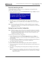
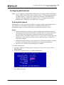
PXE Boot Process .................................................................................... 25
Remotely Installing with PXE for Windows Server 2008, 2008 R2, 2012,
and 2012 R2 .......................................................................................... 27
Remotely Installing with PXE for Linux and Citrix Servers ................................. 27
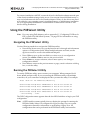
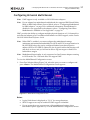
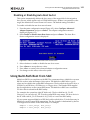
Using the PXESelect Utility ........................................................................ 28
Navigating the PXESelect Utility...............................................................28
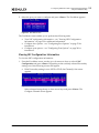
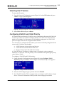
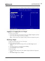
Running the PXESelect Utility..................................................................28
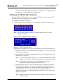
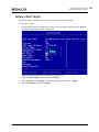
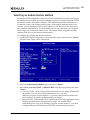
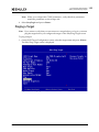
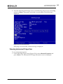
Setting Up a PXE Bootable Network...........................................................29
Personality Option ...............................................................................30
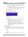
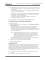
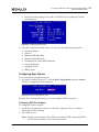
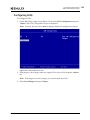
Configuring the Custom Personality Selection .................................................. 31
Advanced Mode Support ........................................................................32
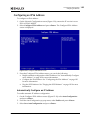
Configuring Ports When Multichannel is Disabled or Not Supported .....................34
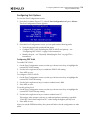
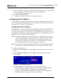
Configuring PXE Boot Support...................................................................... 34
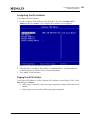
Configuring SR-IOV................................................................................... 35
Configuring the PXE VLAN ID and Priority ........................................................ 35
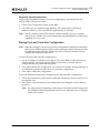
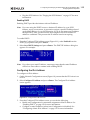
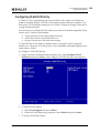
Physically Identifying the Port ..................................................................... 36
Erasing Ports and Controller Configuration ...................................................... 36
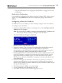
Configuring Universal Multichannel ...........................................................37
Configuring Minimum and Maximum Bandwidth................................................. 38
Configuring LPVID .................................................................................... 38
Configuring Multichannel for IBM Adapters ..................................................39
Multichannel Modes.................................................................................. 40
Multichannel Configuration......................................................................... 40
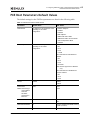
PXE Boot Parameters Default Values ............................................................ 42
3. Configuring PXE Boot for NIC on OCe14000-series Adapters ........................ 43
Pre-OS ................................................................................................. 43
PXE Boot Process .................................................................................... 43
Boot Version 10.2 for NIC, iSCSI, FCoE, and RoCE Protocols User Manual
P010097-01B Rev. A
3
Table of Contents
Remotely Installing with PXE for Windows Server 2008, 2008 R2, 2012,
and 2012 R2 .......................................................................................... 45
Remotely Installing with PXE for Linux and Citrix Servers ................................. 45
Using the PXESelect Utility ........................................................................ 46
Navigating the PXESelect Utility...............................................................46
Running the PXESelect Utility..................................................................46
Setting Up a PXE Bootable Network...........................................................47
Configuring Ports When Multichannel is Disabled or Not Supported .....................49
Configuring Personality ............................................................................. 49
Configuring SR-IOV................................................................................... 50
Configuring NIC Mode ............................................................................... 51
Loading Default Settings ............................................................................ 51
Selecting a Port ...................................................................................... 51
Viewing NIC Configuration Information........................................................... 52
Configuring Boot Options ........................................................................... 53
Configuring Port Options............................................................................ 54
Erasing Ports and Controller Configuration ...................................................... 55
Configuring Multichannel .......................................................................56
Enabling Multichannel............................................................................... 56
Configuring Personality ............................................................................. 57
Loading Default Settings ............................................................................ 58
Selecting a Port ...................................................................................... 59
Configuring Multichannel Options ................................................................. 60
Configuring Minimum and Maximum Bandwidth................................................. 61
Configuring LPVID .................................................................................... 61
Configuring Multichannel for IBM Adapters ..................................................62
Multichannel Modes.................................................................................. 63
Multichannel Configuration......................................................................... 63
PXE Boot Parameters Default Values ............................................................ 65
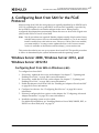
4. Configuring Boot from SAN for the FCoE Protocol..................................... 67
Windows Server 2008, Windows Server 2012, and Windows Server 2012
R2....................................................................................................... 67
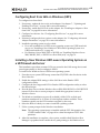
Configuring Boot from SAN on Windows (x64) ...............................................67
Configuring Boot from SAN on Windows (UEFI)..............................................68
Installing a New Windows UEFI-aware Operating System on a UEFI-based
x64 Server.........................................................................................68
Directing a UEFI-based Server to a Windows Server 2008, 2008 R2, 2012,
or 2012 R2 Operating System Image (Installed as UEFI-aware) Already
Installed on the SAN .............................................................................69
GUID Partition Table ............................................................................69
Boot Version 10.2 for NIC, iSCSI, FCoE, and RoCE Protocols User Manual
P010097-01B Rev. A
4
Table of Contents
Installing Windows Server 2008, 2008 R2, 2012, or 2012 R2 on a Boot
Disk (x64) ............................................................................................. 70
Linux, Citrix, and VMware......................................................................... 71
Configuring Boot from SAN on Linux, Citrix, or VMware (x86 and x64) .................71
Configuring Boot from SAN on Linux (UEFI) ..................................................71
Solaris ................................................................................................. 72
Configuring Boot from SAN on Solaris SFS (x86 and x64) ..................................72
Determining LUNs to Select for Boot from SAN .............................................72
Configuring Boot from SAN on Solaris SFS (SPARC) .........................................73
Installing Solaris from a Network Image......................................................73
Installing Solaris by Migrating an Image from a Local SCSI Disk ..........................75
Booting Solaris 10 from the Network on SPARC Machines .................................78
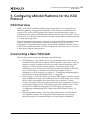
5. Configuring x86/x64 Platforms for the iSCSI Protocol ................................ 80
iSCSI Overview ....................................................................................... 80
Constructing a Basic iSCSI SAN.................................................................... 80
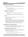
Managing an iSCSI Session ......................................................................... 81
Logging into an iSCSI Session...................................................................81
Security............................................................................................81
CHAP Authentication ................................................................................ 81
Configuring for the iSCSI Protocol ............................................................... 81
Setting Up Boot from SAN for iSCSI ...........................................................81
Windows Server ...................................................................................... 82
Linux and Citrix Servers............................................................................. 82
ESXi Server ............................................................................................ 83
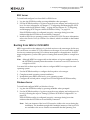
Booting from SAN for iSCSI MPIO ..............................................................83
Windows Server ...................................................................................... 83
Linux and Citrix Servers............................................................................. 84
ESXi 5.0, 5.1, or 5.5 Server......................................................................... 86
6. Using the FCoE Boot BIOS Utility for x86 and x64 Architectures................... 87
Navigating the FCoE BIOS Utility ................................................................. 87
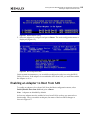
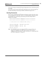
Starting the FCoE BIOS Utility .................................................................... 87
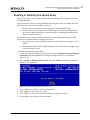
Enabling an Adapter to Boot from SAN.......................................................... 88
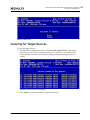
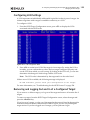
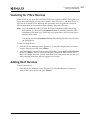
Scanning for Target Devices ...................................................................... 89
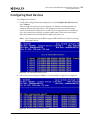
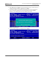
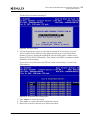
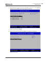
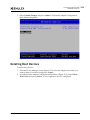
Configuring Boot Devices .......................................................................... 90
Configuring CEE Parameters ...................................................................... 93
Configuring Advanced Adapter Parameters.................................................... 93
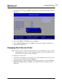
Changing the Default AL_PA ...................................................................94
Boot Version 10.2 for NIC, iSCSI, FCoE, and RoCE Protocols User Manual
P010097-01B Rev. A
5
Table of Contents
Changing the PLOGI Retry Timer ..............................................................96
Enabling or Disabling the Spinup Delay.......................................................97
Setting Auto Scan ................................................................................98
Enabling or Disabling EDD 3.0..................................................................99
Enabling or Disabling the Start Unit Command..............................................99
Enabling or Disabling the Environment Variable .......................................... 100
Enabling or Disabling Auto Boot Sector..................................................... 101
Using Multi-Path Boot from SAN .................................................................101
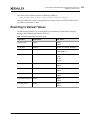
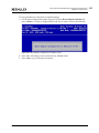
Resetting to Default Values ......................................................................102
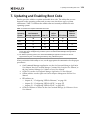
7. Updating and Enabling Boot Code....................................................... 104
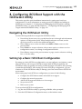
8. Configuring iSCSI Boot Support with the iSCSISelect Utility ....................... 105
Navigating the iSCSISelect Utility ...............................................................105
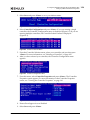
Setting Up a Basic iSCSI Boot Configuration...................................................105
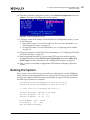
Booting the System ................................................................................107
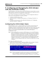
9. Configuring and Managing the iSCSI Initiator with the iSCSISelect
Utility ............................................................................................ 108
Configuring the iSCSI Initiator Name ...........................................................108
Selecting a Controller .............................................................................109
Viewing the Controller Properties ..............................................................110
Enabling Boot Support......................................................................... 110
Enabling IPv4 Boot Target Discovery using DHCP ......................................... 111
Enabling the MPIO Port ....................................................................... 111
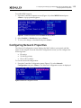
Configuring Network Properties.................................................................112
Selecting the IP Version....................................................................... 113
Configuring VLAN ID and VLAN Priority ..................................................... 113
Configuring the IP Address ................................................................... 114
Configuring the IPv4 Address..................................................................... 114
Configuring the IPv6 Address..................................................................... 115
Configuring a Static IPv4 Address ............................................................... 116
Configuring a Static IPv6 Address ............................................................... 117
Pinging the iSCSI Initiator......................................................................... 117
Identifying a Port...................................................................................118
Erasing the Current Configuration ..............................................................118
10. Configuring and Managing iSCSI Targets with the iSCSISelect Utility........... 119
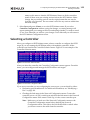
Adding iSCSI Targets ...............................................................................119
Using SendTargets Discovery to Add an iSCSI Target ..................................... 120
Boot Version 10.2 for NIC, iSCSI, FCoE, and RoCE Protocols User Manual
P010097-01B Rev. A
6
Table of Contents
Manually Adding an iSCSI Target ............................................................ 122
Managing an iSCSI Target .........................................................................123
Viewing Target Information .................................................................. 123
Editing a Target Configuration............................................................... 124
Setting an ISID Value .............................................................................. 125
Enabling CHAP Authentication ................................................................... 125
Pinging a Target.................................................................................... 128
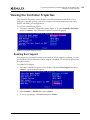
Viewing Advanced Target Properties ....................................................... 128
Configuring LUN Settings ..................................................................... 129
Removing and Logging Out and In of a Configured Target .............................. 129
Booting the System ............................................................................ 130
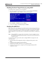
Discovering Targets through DHCP for iSCSI ..................................................131
Enabling DHCP Discovery Through the iSCSISelect Utility .................................133
11. Configuring UEFI for Ethernet ......................................................... 134
Overview .............................................................................................134
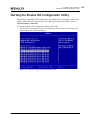
Navigating the Emulex NIC Configuration Utility ............................................134
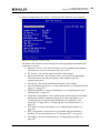
Starting the Emulex NIC Configuration Utility................................................135
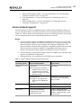
Advanced Mode Support ...................................................................... 137
Configuring Boot Mode ........................................................................ 138
Configuring iBFT ............................................................................... 139
Changing the iSCSI Name ......................................................................... 140
Selecting Multipath I/O ........................................................................... 140
Configuring CHAP Authentication Mode ........................................................ 140
Configuring Network Settings .................................................................... 141
Configuring the Primary and Secondary Targets .............................................. 143
Configuring Personality ....................................................................... 145
Selecting the NIC+RoCE Personality............................................................. 147
Selecting the Custom Personality ............................................................... 148
Configuring the Controller When Multichannel is Disabled or Not Supported ........ 149
Viewing the Configuration ........................................................................ 150
Configuring SR-IOV................................................................................. 150
Configuring NIC Mode ............................................................................. 151
Saving the Current Configuration ............................................................... 152
Configuring Universal Multichannel ......................................................... 153
Viewing the Configuration ........................................................................ 155
Configuring Minimum and Maximum Bandwidth............................................... 156
Configuring the LPVID ............................................................................. 157
Saving the Configuration.......................................................................... 158
Configuring Multichannel for IBM Adapters ................................................ 158
Boot Version 10.2 for NIC, iSCSI, FCoE, and RoCE Protocols User Manual
P010097-01B Rev. A
7
Table of Contents
Multichannel Modes................................................................................ 159
Multichannel Configuration....................................................................... 159
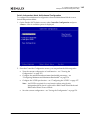
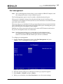
Port Management .............................................................................. 163
Feature on Demand............................................................................ 164
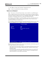
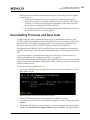
Downloading Firmware and Boot Code ........................................................165
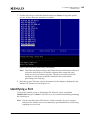
Identifying a Port...................................................................................168
Erasing Ports and Controller Configuration ...................................................169
UEFI NIC Diagnostics........................................................................... 170
EFI_DRIVER_DIAGNOSTICS_PROTOCOL.......................................................... 170
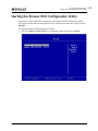
12. Configuring UEFI for iSCSI............................................................... 172
Overview .............................................................................................172
Navigating the Emulex iSCSI Configuration Utility...........................................172
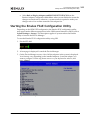
Starting the Emulex iSCSI Configuration Utility ..............................................173
Configuring MPIO ...................................................................................174
Configuring Boot Support .........................................................................176
Viewing the Controller Properties ..............................................................177
Configuring the Network..........................................................................178
Configuring the IP Version .................................................................... 179
Configuring an IPV4 Address ................................................................. 180
Automatically Assigning an IP Address through a DHCP Server ............................. 180
Manually Assigning an IP Address ................................................................ 181
Pinging the iSCSI Initiator......................................................................... 181
Configuring an IPV6 Address ................................................................. 182
Automatically Configure an IP Address ......................................................... 182
Configuring the IPv6 Address..................................................................... 183
Pinging the iSCSI Initiator......................................................................... 183
Configuring VLAN ID/Priority................................................................. 184
Updating Firmware ................................................................................185
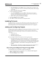
Adding and Configuring Targets .................................................................185
Discovering and Adding Boot Targets through DHCP ..................................... 185
Using SendTargets Discovery to Add an iSCSI Target ..................................... 186
Manually Adding, Discovering, and Managing Boot Targets ............................. 188
Setting a Boot Target ......................................................................... 190
Selecting an Authentication Method ........................................................ 191
Pinging a Target................................................................................ 192
Viewing Advanced Properties ................................................................ 193
Logging In or Logging Out of a Target ...................................................... 194
Deleting a Target .............................................................................. 194
Boot Version 10.2 for NIC, iSCSI, FCoE, and RoCE Protocols User Manual
P010097-01B Rev. A
8
Table of Contents
Configuring LUNs............................................................................... 195
iSNS Configuration ............................................................................. 196
Enabling iSNS Discovery ........................................................................... 197
Enabling iSNS Server Discovery via DHCP ...................................................... 197
Configuring the iSNS Server IP Address and TCP Port Number Manually .................. 198
Discovering Targets Using the iSNS Server ..................................................... 200
Erasing the Configuration.........................................................................201
13. Configuring UEFI for FCoE .............................................................. 202
Overview .............................................................................................202
Navigating the Emulex FCoE Configuration Utility ..........................................202
Starting the Emulex FCoE Configuration Utility..............................................203
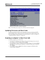
Updating Firmware and Boot Code .............................................................204
Enabling an Adapter to Boot from SAN.........................................................204
Configuring CEE FCF Parameters................................................................205
Scanning for Fibre Devices .......................................................................207
Adding Boot Devices ...............................................................................207
Deleting Boot Devices .............................................................................209
Changing Boot Device Order .....................................................................210
Configuring Adapter Parameters ................................................................213
Changing the PLOGI Retry Timer ............................................................ 213
Changing the Maximum LUNs per Target................................................... 214
Changing Boot Target Scan Method ......................................................... 215
Changing Device Discovery Delay............................................................ 217
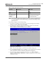
Resetting Emulex Adapters to Default Values ................................................218
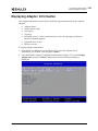
Displaying Adapter Information .................................................................220
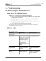
14. Troubleshooting .......................................................................... 221
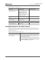
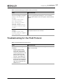
Troubleshooting for the NIC Protocol ..........................................................221
Issues During the PXE Boot Process ......................................................... 221
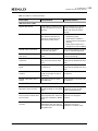
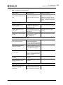
PXE Error Codes ................................................................................ 221
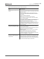
Troubleshooting for the iSCSI Protocol ........................................................224
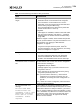
Troubleshooting for the FCoE Protocol ........................................................227
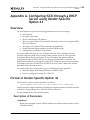
Appendix A. Configuring iSCSI through a DHCP Server using
Vendor-Specific Option 43 .................................................. 228
Overview .............................................................................................228
Format of Vendor-Specific Option 43 ..........................................................228
Description of Parameters.................................................................... 228
Boot Version 10.2 for NIC, iSCSI, FCoE, and RoCE Protocols User Manual
P010097-01B Rev. A
9
Table of Contents
Example ......................................................................................... 229
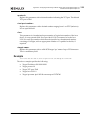
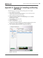
Appendix B. Example for Installing and Configuring Linux or Citrix for
PXE Boot and UEFI Boot...................................................... 230
Linux and Citrix PXE Server Remote Installation Procedure ..............................230
PXE Server ...................................................................................... 231
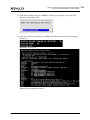
NFS Server Configuration Script ................................................................. 231
TFTP Server Setup ................................................................................. 232
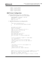
DHCP Server Configuration ....................................................................... 233
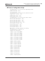
PXE Boot Server Configuration .................................................................. 234
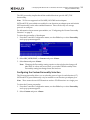
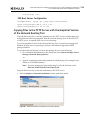
Copying Files to the TFTP Server with the Graphical Version of the
Network Booting Tool ......................................................................... 234
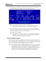
Configuring the Host .............................................................................. 236
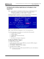
Enabling the PXE Client with a PXE-enabled Adapter ........................................ 237
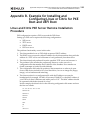
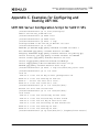
Appendix C. Examples for Configuring and Booting UEFI NIC ........................ 238
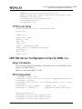
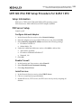
UEFI NIC Server Configuration Script for SLES11 SPx .......................................238
NFS Server Configuration Script ............................................................. 239
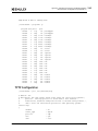
DHCP Server Configuration ................................................................... 240
TFTP Server Setup ............................................................................. 241
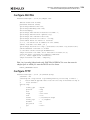
UEFI NIC Server Configuration Script for RHEL 6.x..........................................241
Setup Information.............................................................................. 241
NFS Configuration.............................................................................. 241
TFTP Configuration ............................................................................ 242
PXE Configuration.............................................................................. 243
Configuring DHCP .............................................................................. 244
Configuring the IBM HS22 Blade with e-Raptor MEZZ .......................................245
UEFI NIC IPv6 PXE Setup Procedure for SLES11 SP2 ........................................253
Setup Information.............................................................................. 253
PXE Server Setup............................................................................... 253
Configure Network Adapter ...................................................................... 253
Disable Firewall .................................................................................... 253
Install Services ..................................................................................... 253
Configure DHCPD6 ............................................................................. 254
Configure TFTP ................................................................................. 254
Configure ELILO Boot Loader..................................................................... 255
Create /tftpboot/elilo.conf with the Following Contents................................... 255
Copy Installation Files for FTP Transfer ........................................................ 255
Configure FTP to Enable Support for IPv6...................................................... 255
Restart the Necessary Services .................................................................. 260
PXE Client Setup ............................................................................... 260
Boot Version 10.2 for NIC, iSCSI, FCoE, and RoCE Protocols User Manual
P010097-01B Rev. A
10
Table of Contents
Appendix D. Example for Installing and Booting UEFI FCoE........................... 268
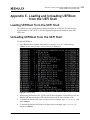
Appendix E. Loading and Unloading UEFIBoot from the UEFI Shell ................. 270
Loading UEFIBoot from the UEFI Shell .........................................................270
Unloading UEFIBoot from the UEFI Shell ......................................................270
Appendix F. Dell UEFI ........................................................................ 271
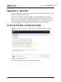
Accessing the Main Configuration Page ........................................................271
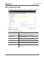
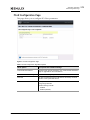
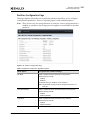
Main Configuration Page ..........................................................................272
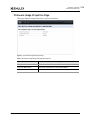
Firmware Image Properties Page ............................................................ 274
FCoE Configuration Page...................................................................... 275
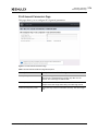
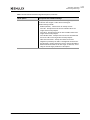
FCoE General Parameters Page.................................................................. 276
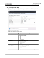
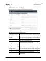
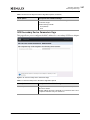
NIC Configuration Page ....................................................................... 278
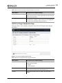
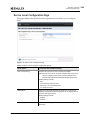
iSCSI Configuration Page...................................................................... 280
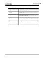
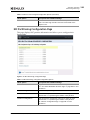
iSCSI General Parameters Page .................................................................. 281
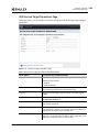
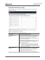
iSCSI Initiator Parameters Page.................................................................. 283
iSCSI First Target Parameters Page ............................................................. 284
iSCSI Second Target Parameters Page .......................................................... 286
iSCSI Secondary Device Parameters Page ...................................................... 287
Device Level Configuration Page ............................................................ 288
NIC Partitioning Configuration Page ........................................................ 289
Global Bandwidth Allocation Page .............................................................. 290
Partition Configuration Page ..................................................................... 291
Appendix G. Configuring PXE Boot for NIC on Dell OCe10100-based
Systems.......................................................................... 293
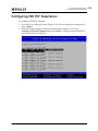
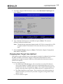
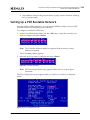
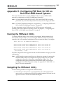
Running the PXESelect Utility ...................................................................293
Navigating the PXESelect Utility ................................................................293
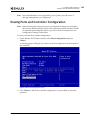
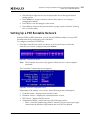
Setting Up a PXE Bootable Network ............................................................294
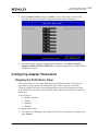
Configuring the Hide Setup Prompt ............................................................. 295
Configuring the Banner Message Timeout...................................................... 295
Setting the Configured Port Speed .............................................................. 295
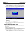
Configuring PXE Boot Support.................................................................... 296
Configuring the Boot Retry Count ............................................................... 296
Configuring Wake on LAN ......................................................................... 296
Configuring Flow Control ......................................................................... 296
Configuring SR-IOV................................................................................. 297
Configuring the PXE VLAN ID and Priority ...................................................... 297
Physically Identifying the Port ................................................................... 297
Erasing Ports and Controller Configuration .................................................... 298
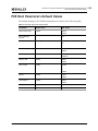
PXE Boot Parameters Default Values ...........................................................299
Boot Version 10.2 for NIC, iSCSI, FCoE, and RoCE Protocols User Manual
P010097-01B Rev. A
11
Table of Contents
Appendix H. Configuring PXE Boot for NIC on Dell OCe14000-based
Systems.......................................................................... 300
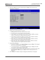
Running the PXESelect Utility ...................................................................300
Navigating the PXESelect Utility ................................................................300
Setting Up a PXE Bootable Network ............................................................301
Configuring NPar ............................................................................... 303
Selecting the Protocol ............................................................................ 304
Configuring Minimum and Maximum Bandwidth............................................... 305
Enabling NParEP Support ......................................................................... 305
Configuring Boot Options ..................................................................... 306
Configuring PXE Boot Support.................................................................... 307
Configuring the Hide Setup Prompt ............................................................. 307
Configuring the Banner Message Timeout...................................................... 307
Configuring the Boot Retry Count ............................................................... 307
Configuring Port Options...................................................................... 308
Setting the Configured Port Speed .............................................................. 308
Configuring Wake on LAN ......................................................................... 308
Configuring Flow Control ......................................................................... 309
Configuring the PXE VLAN ID and Priority ...................................................... 309
Physically Identifying the Port ................................................................... 309
Erasing Ports and Controller Configuration .................................................... 310
PXE Boot Parameters Default Values ...........................................................310
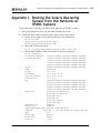
Appendix I. Booting the Solaris Operating System from the Network on
SPARC Systems................................................................. 312
Boot Version 10.2 for NIC, iSCSI, FCoE, and RoCE Protocols User Manual
P010097-01B Rev. A
12
List of Figures
List of Figures
Figure 2-1
Figure 2-2
Figure 2-3
Figure 2-4
Figure 2-5
Figure 2-6
Figure 2-7
Figure 2-8
Figure 2-9
Figure 2-10
Figure 2-11
Figure 2-12
Figure 2-13
Figure 3-1
Figure 3-2
Figure 3-3
Figure 3-4
Figure 3-5
Figure 3-6
Figure 3-7
Figure 3-8
Figure 3-9
Figure 3-10
Figure 3-11
Figure 3-12
Figure 3-13
Figure 3-14
Figure 3-15
Figure 3-16
Figure 3-17
Figure 3-18
Figure 6-1
Figure 6-2
Figure 6-3
Figure 6-4
Figure 6-5
Figure 6-6
Figure 6-7
Figure 6-8
PXE Boot Process ..........................................................................26
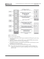
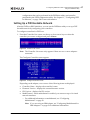
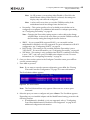
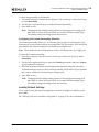
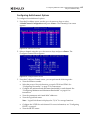
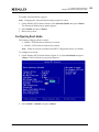
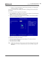
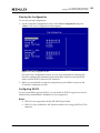
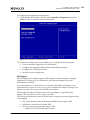
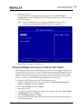
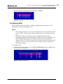
Controller Selection Menu ...............................................................29
Controller Configuration Menu ..........................................................29
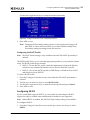
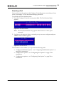
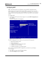
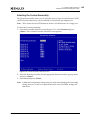
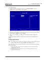
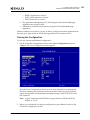
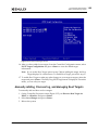
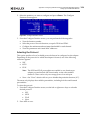
Port Selection Menu ......................................................................30
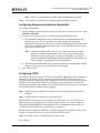
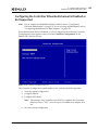
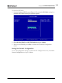
Controller Configuration Menu – Personality Selection..............................31
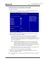
Custom Personality Selection on Multichannel Configuration Screen .............32
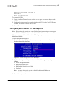
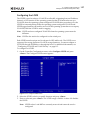
Controller Configuration Menu – Advanced Mode Support Selection ..............33
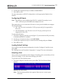
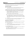
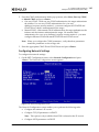
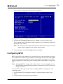
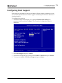
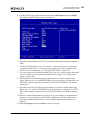
Port Configuration Screen ...............................................................34
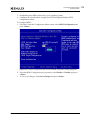
Configure PXE VLAN ID/Priority Menu..................................................35
Port Identification Screen ...............................................................36
MultiChannel Configuration Screen.....................................................37
Controller Configuration Screen - IBM Adapters......................................39
IBM Virtual Fabric Mode Configuration Screen........................................41
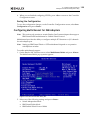
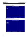
PXE Boot Process ..........................................................................44
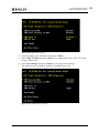
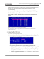
Controller List Screen ....................................................................47
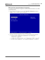
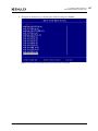
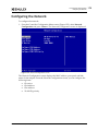
Configure Controller Screen .............................................................47
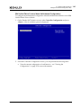
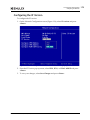
Port Selection Menu ......................................................................48
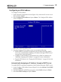
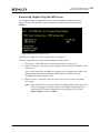
Configure Controller Screen – Personality Selection.................................50
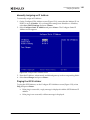
Port Selection Menu ......................................................................51
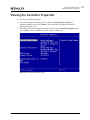
Port Menu Screen .........................................................................52
Channel(s) List Screen....................................................................52
Configure Channel Screen ...............................................................53
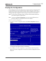
Boot Configuration Screen ...............................................................53
Port Configuration Screen ...............................................................54
Configure Controller Screen – MultiChannel Enabled ................................56
Port Selection Menu ......................................................................59
Port Menu Screen .........................................................................59
Channels List Screen......................................................................60
Configure Channel Screen ...............................................................60
Controller Configuration Screen - IBM Adapters......................................62
IBM Virtual Fabric Mode MultiChannel Configuration Screen .......................64
Emulex Adapter Listing...................................................................88
Main Configuration Menu.................................................................88
BIOS Status .................................................................................89
Devices Present on the Adapter ........................................................89
List of Saved Boot Devices Screen ......................................................90
Device Selection List Example Screen .................................................90
LUN Listing Screen ........................................................................91
Boot Device Selected .....................................................................91
Boot Version 10.2 for NIC, iSCSI, FCoE, and RoCE Protocols User Manual
P010097-01B Rev. A
13
List of Figures
Figure 6-9
Figure 6-10
Figure 6-11
Figure 6-12
Figure 6-13
Figure 6-14
Figure 6-15
Figure 6-16
Figure 6-17
Figure 6-18
Figure 6-19
Figure 6-20
Figure 6-21
Figure 6-22
Figure 8-1
Figure 8-2
Figure 8-3
Figure 8-4
Figure 8-5
Figure 9-1
Figure 9-2
Figure 9-3
Figure 9-4
Figure 9-5
Figure 9-6
Figure 9-7
Figure 9-8
Figure 9-9
Figure 9-10
Figure 9-11
Figure 9-12
Figure 9-13
Figure 9-14
Figure 9-15
Figure 9-16
Figure 9-17
Figure 10-1
Figure 10-2
Figure 10-3
Figure 10-4
Figure 10-5
Boot Devices Menu ........................................................................92
Primary Boot Device Set Up Screen ....................................................92
FCF Listing..................................................................................93
Save Edited Boot Record Dialog Box ...................................................93
Advanced Adapter Configuration Menu ................................................94
Change Default ALPA Screen ............................................................95
Change the PLOGI Retry Timer Screen.................................................96
Enable or Disable Spinup Delay Screen ................................................97
Set Auto Scan Menu .......................................................................98
Enable or Disable EDD 3.0 Screen ......................................................99
Enable or Disable Start Unit Command Screen ..................................... 100
Enable or Disable Environment Variable Screen.................................... 100
Enable or Disable Auto Boot Sector Format Screen................................ 101
Reset Adapter Configuration to Defaults Screen ................................... 103
iSCSI Initiator Configuration Menu.................................................... 106
Controller Selection Menu ............................................................. 106
Controller Configuration Menu ........................................................ 106
Controller Properties Screen .......................................................... 106
Network Configuration Screen ........................................................ 107
iSCSI Initiator Configuration Screen .................................................. 108
Controller Selection Menu ............................................................. 109
Controller Configuration Menu ........................................................ 109
Controller Properties Screen .......................................................... 110
Controller Properties Screen with Boot Support Pop-up Menu................... 110
Controller Properties Screen with Discover IPv4 Boot Target via DHCP
Pop-up Menu ............................................................................. 111
Controller Properties Screen with MPIO Port Pop-up Menu....................... 112
Network Configuration Screen ........................................................ 112
Network Configuration Screen with IP Version Pop-up Menu..................... 113
Configure VLAN ID/Priority Screen ................................................... 113
Configure IPv4 Address Screen ........................................................ 114
DHCP IP Address Dialog Box ........................................................... 115
Configure IPv6 Address Screen ........................................................ 115
Static IP Address Dialog Box for IPv4................................................. 116
Static IP Address Dialog Box for IPv6................................................. 117
Successful Ping Screen ................................................................. 117
Port Identification Screen ............................................................. 118
Controller Configuration Menu ........................................................ 120
Add/Ping iSCSI Target dialog box ..................................................... 120
Targets Discovered via SendTargets Screen......................................... 121
iSCSI Target Configuration Screen .................................................... 122
iSCSI Target Configuration Information.............................................. 123
Boot Version 10.2 for NIC, iSCSI, FCoE, and RoCE Protocols User Manual
P010097-01B Rev. A
14
List of Figures
Figure
Figure
Figure
Figure
Figure
Figure
Figure
Figure
Figure
Figure
Figure
Figure
Figure
Figure
Figure
Figure
Figure
Figure
Figure
Figure
Figure
Figure
Figure
Figure
Figure
Figure
Figure
Figure
Figure
Figure
Figure
Figure
Figure
Figure
Figure
Figure
Figure
Figure
Figure
Figure
10-6
10-7
10-8
10-9
10-10
10-11
10-12
10-13
11-1
11-2
11-3
11-4
11-5
11-6
11-7
11-8
11-9
11-10
11-11
11-12
11-13
11-14
11-15
11-16
11-17
11-18
11-19
11-20
11-21
11-22
11-23
11-24
11-25
11-26
11-27
11-28
11-29
12-1
12-2
12-3
Edit/Ping iSCSI Target Dialog Box .................................................... 124
One-way Chap Configuration Dialog Box ............................................ 126
Mutual CHAP Configuration Dialog Box .............................................. 127
Successful Ping Screen ................................................................. 128
Advanced Target Properties Screen .................................................. 128
LUN Configuration Menu ............................................................... 129
DHCP Server Screen..................................................................... 131
DHCP Server Scope Options............................................................ 132
Emulex NIC Configuration Utility Network Screen ................................. 135
Emulex NIC Selection Screen .......................................................... 136
Boot Mode Pop-up Menu ............................................................... 138
iBFT Configuration Screen ............................................................. 139
Network Configuration Screen ........................................................ 141
Primary Target Screen.................................................................. 143
Personality Selection Screen with Pop-up Menu ................................... 146
NIC+RoCE Profile Screen with Pop-Up Menu ........................................ 147
Custom Personality Selection Screen ................................................ 148
Controller Configuration Screen ...................................................... 149
View Configuration Screen............................................................. 150
Configure SRIOV Screen ................................................................ 151
Configure NIC Mode Pop-up Menu .................................................... 152
Controller Configuration Screen ...................................................... 154
Multichannel Configuration for Function 0 Screen ................................. 155
Configure Bandwidth Screen .......................................................... 156
Configure LPVID Screen ................................................................ 157
Multichannel Mode Dialog Box ........................................................ 158
IBM Virtual Fabric Mode Controller Configuration Screen ........................ 160
IBM Unified Fabric Protocol Mode Controller Configuration Screen ............. 161
Switch Independent Mode Controller Configuration Screen ...................... 162
Port Management Screen .............................................................. 163
Feature On Demand Screen............................................................ 164
UEFI Shell with Firmware and Boot Code File ...................................... 165
Emulex Flash Update Utility ........................................................... 166
Emulex Flash Update Utility with Directory Name Dialog Box ................... 166
Emulex Flash Update Utility with Flash File Name Dialog Box ................... 167
Emulex Flash Update Utility, Flash Updating ....................................... 168
Erase Configuration Screen ............................................................ 169
Storage Screen........................................................................... 173
Controller Configuration Menu Screen ............................................... 174
Controller Configuration Menu Screen with MPIO Configuration Setting
Highlighted ............................................................................... 175
Boot Version 10.2 for NIC, iSCSI, FCoE, and RoCE Protocols User Manual
P010097-01B Rev. A
15
List of Figures
Figure 12-4
Figure 12-5
Figure 12-6
Figure 12-7
Figure
Figure
Figure
Figure
Figure
Figure
Figure
Figure
Figure
Figure
Figure
Figure
Figure
Figure
Figure
Figure
Figure
Figure
Figure
Figure
Figure
Figure
Figure
Figure
Figure
Figure
Figure
Figure
Figure
Figure
Figure
Figure
Figure
Figure
Figure
Figure
12-8
12-9
12-10
12-11
12-12
12-13
12-14
12-15
12-16
12-17
12-18
12-19
12-20
12-21
12-22
12-23
12-24
12-25
12-26
12-27
12-28
12-29
13-1
13-2
13-3
13-4
13-5
13-6
13-7
13-8
13-9
13-10
13-11
13-12
13-13
13-14
Controller Configuration Menu Screen with Boot Support Setting
Highlighted ............................................................................... 176
Controller Properties Screen .......................................................... 177
Network Configuration Screen ........................................................ 178
Network Configuration Menu Screen with IP Version Setting
Highlighted ............................................................................... 179
Configure IPV4 Address Screen........................................................ 180
Configure Static IP Address Screen ................................................... 181
Configure IPV6 Address Screen........................................................ 182
Configure IPV6 Address Settings Screen ............................................. 183
Configure VLAN/ID Priority Screen ................................................... 184
iSCSI Target Configuration Screen .................................................... 186
Discovered Targets Screen............................................................. 188
Add/Ping iSCSI Target Screen ......................................................... 189
Boot Target Option on the Edit/Ping Target Screen............................... 190
Authentication Method Option on the Edit/Ping Target Screen ................. 191
Edit/Ping Target Screen................................................................ 192
Successful Target Ping ................................................................. 193
Advanced iSCSI Target Information Screen.......................................... 194
LUN Configuration Screen.............................................................. 195
iSCSI Target Configuration Screen .................................................... 196
iSNS Configuration Screen ............................................................. 196
iSNS Discovery Mode Screen ........................................................... 197
iSNS Server Discovery via DHCP Screen .............................................. 198
iSNS Server IP Screen ................................................................... 199
Available Servers Screen ............................................................... 199
iSNS Server Options Screen ............................................................ 200
Erase Configuration Screen ............................................................ 201
Exiting the EFI Shell .................................................................... 203
Device Manager Screen................................................................. 203
Emulex Adapter Configuration Main Menu .......................................... 204
CEE Record Selection List.............................................................. 205
CEE FCF Record Information........................................................... 206
SAN Discovery Targets List............................................................. 208
LUN Listing ............................................................................... 208
Commit/Discard Change ............................................................... 209
Delete Boot Device Screen ............................................................ 210
Change Boot Device Order Screen .................................................... 211
Boot Device Order Screen.............................................................. 211
Change Boot Device Order Screen .................................................... 212
Change Boot Device Order Screen with Revised Boot Order ..................... 212
Change Boot Device Order ............................................................. 213
Boot Version 10.2 for NIC, iSCSI, FCoE, and RoCE Protocols User Manual
P010097-01B Rev. A
16
List of Figures
Figure 13-15
Figure 13-16
Figure 13-17
Figure 13-18
Figure 13-19
Figure 13-20
Figure B-1
Figure B-2
Figure B-3
Figure B-4
Figure B-5
Figure B-6
Figure C-1
Figure C-2
Figure C-3
Figure C-4
Figure C-5
Figure C-6
Figure C-7
Figure C-8
Figure C-9
Figure C-10
Figure C-11
Figure C-12
Figure C-13
Figure C-14
Figure C-15
Figure C-16
Figure C-17
Figure C-18
Figure C-19
Figure C-20
Figure C-21
Figure C-22
Figure C-23
Figure C-24
Figure C-25
Figure C-26
Figure C-27
Figure C-28
Figure C-29
Figure C-30
PLOGI Retry Timer ...................................................................... 214
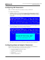
Configure HBA Parameters – Maximum LUNs/Target Field ....................... 215
Configure HBA Parameters – Boot Target Scan Method Menu .................... 216
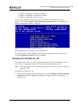
Configure HBA Parameters – Delay Device Discovery .............................. 217
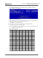
Set Adapter Defaults.................................................................... 219
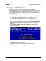
Controller Information ................................................................. 220
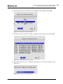
Network Installation and Diskless Environment Window .......................... 234
Configure Network Installations Window ............................................ 235
Network Installation Dialog Window ................................................. 235
Network Installation and Diskless Environment Window with IP Address ...... 236
Edit Dialog Box .......................................................................... 236
Enabling Network Boot ................................................................. 237
System Configuration and Boot Management Screen .............................. 245
Boot Manager Screen ................................................................... 246
File Explorer Screen .................................................................... 247
ELILO Boot Message ..................................................................... 247
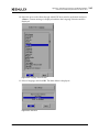
Language Selection Menu .............................................................. 248
Main Menu ................................................................................ 248
Expert Menu.............................................................................. 249
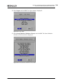
Kernel Modules (Hardware Drivers) Menu ........................................... 249
Driver Update Medium Selection Listing............................................. 250
Driver Update List Dialog Box ......................................................... 250
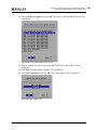
Source Medium Selection Menu ....................................................... 250
Network Protocol Selection Menu .................................................... 251
Network Device Selection Listing ..................................................... 251
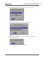
NFS Server IP Address Dialog Box ..................................................... 251
Server Directory Dialog Box ........................................................... 252
Starting Script ........................................................................... 252
Driver Update Confirmation ........................................................... 252
UEFI Boot Settings Screen ............................................................. 260
Boot Manager Main Menu............................................................... 261
UEFI Boot Menu .......................................................................... 262
File Explorer Screen .................................................................... 262
Language Selection Menu .............................................................. 263
Main Menu ................................................................................ 263
Expert Menu.............................................................................. 264
Kernel Modules (Hardware Drivers) Menu ........................................... 264
Driver Update Medium Selection List ................................................ 265
Source Medium List ..................................................................... 265
Network Protocol List .................................................................. 266
Network Device List .................................................................... 266
Automatic Configuration via DHCP Dialog Box...................................... 266
Boot Version 10.2 for NIC, iSCSI, FCoE, and RoCE Protocols User Manual
P010097-01B Rev. A
17
List of Figures
Figure C-31
Figure C-32
Figure D-1
Figure D-2
Figure E-1
Figure F-1
Figure F-2
Figure F-3
Figure F-4
Figure F-5
Figure F-6
Figure F-7
Figure F-8
Figure F-9
Figure F-10
Figure F-11
Figure F-12
Figure F-13
Figure F-14
Figure F-15
Figure F-16
Figure G-1
Figure G-2
Figure G-3
Figure G-4
Figure G-5
Figure H-1
Figure H-2
Figure H-3
Figure H-4
Figure H-5
Figure H-6
Figure H-7
Figure H-8
Figure H-9
FTP Server IPv6 Address Dialog Box .................................................. 267
Server Directory Path Dialog Box ..................................................... 267
Partitions Tab............................................................................ 268
UEFI FCoE Start Options................................................................ 269
Driver Listing............................................................................. 270
Device Settings Page.................................................................... 271
Main Configuration Page .............................................................. 272
Firmware Image Properties Page .................................................... 274
FCoE Configuration Page .............................................................. 275
FCoE General Parameters Page ...................................................... 276
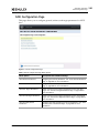
NIC Configuration Page ................................................................ 278
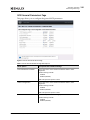
iSCSI Configuration Page .............................................................. 280
iSCSI General Parameters Page ...................................................... 281
iSCSI Initiator Parameters Page ...................................................... 283
iSCSI First Target Parameters Page .................................................. 284
iSCSI Second Target Parameters Page ............................................... 286
iSCSI Secondary Device Parameters Page ........................................... 287
Device Level Configuration Page ..................................................... 288
NIC Partitioning Configuration Page ................................................. 289
Global Bandwidth Allocation Page ................................................... 290
Partition Configuration Page ......................................................... 291
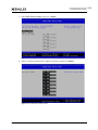
Controller Selection Menu ............................................................. 294
Port Selection Menu .................................................................... 294
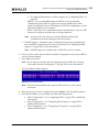
Port Configuration Screen ............................................................. 294
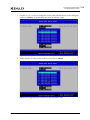
Configure PXE VLAN ID/Priority Menu................................................ 297
Port Identification Screen ............................................................. 297
Controller List Screen .................................................................. 301
Controller Configuration Screen ...................................................... 301
Port Selection Menu .................................................................... 302
Port Menu ................................................................................ 303
Partition(s) List Screen ................................................................. 303
Configure Partition Screen............................................................. 304
Partition(s) List Screen When NParEP is Enabled .................................. 306
Boot Configuration Screen ............................................................. 306
Port Configuration Screen ............................................................. 308
Boot Version 10.2 for NIC, iSCSI, FCoE, and RoCE Protocols User Manual
P010097-01B Rev. A
18
List of Tables
List of Tables
Table 2-1
Table 2-2
Table 3-1
Table 6-1
Table 6-2
Table 7-1
Table 11-1
Table 13-1
Table 14-1
Table 14-2
Table 14-3
Table F-1
Table F-2
Table F-3
Table F-4
Table F-5
Table F-6
Table F-7
Table F-8
Table F-9
Table F-10
Table F-11
Table F-12
Table F-13
Table F-14
Table F-15
Table G-1
Table H-1
Advanced Mode Capabilities (by Operating System).................................33
PXE Boot Parameter Default Values ....................................................42
PXE Boot Parameter Default Values ....................................................65
Valid AL_PA Values........................................................................95
Default Adapter Boot Parameter Values............................................. 102
Utilities that Update and Enable Boot Code ........................................ 104
Advanced Mode Capabilities (by Operating System)............................... 137
Adapter Default Values................................................................. 218
PXE Error Codes ......................................................................... 221
Troubleshooting the iSCSISelect Utility.............................................. 224
Troubleshooting the FCoE Protocol .................................................. 227
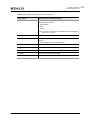
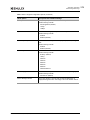
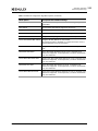
Main Configuration Page Menu Options .............................................. 272
Firmware Image Properties Page Menu Options .................................... 274
FCoE Configuration Page Menu Options.............................................. 275
FCoE General Parameters Page Menu Options...................................... 276
NIC Configuration Page Menu Options ............................................... 278
iSCSI Configuration Page Menu Options.............................................. 280
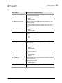
iSCSI General Parameters Page Menu Options ...................................... 281
iSCSI Initiator Parameters Page Menu Options...................................... 283
iSCSI First Target Parameters Page Menu Options ................................. 284
iSCSI Second Target Parameters Page Menu Options .............................. 286
iSCSI Secondary Device Parameters Page Menu Options .......................... 287
Device Level Configuration Page Menu Options .................................... 288
NIC Partitioning Configuration Page Menu Options ................................ 289
Global Bandwidth Allocation Page Menu Options .................................. 290
Partition Configuration Page Menu Options ......................................... 291
PXE Boot Parameter Default Values .................................................. 299
PXE Boot Parameter Default Values .................................................. 310
Boot Version 10.2 for NIC, iSCSI, FCoE, and RoCE Protocols User Manual
P010097-01B Rev. A
19
1. Introduction
Overview
1. Introduction
Overview
This manual describes installing, enabling, and configuring boot code for Emulex®
network interface card (NIC), Internet Small Computer System Interface (iSCSI), and
Fibre Channel over Ethernet (FCoE) adapters. This manual also describes the Emulex
boot from SAN implementation and its operation with distinct hardware and operating
system requirements.
Boot from SAN is the process of booting a server directly from a disk operating system
image located on a storage area network (SAN) by way of Emulex adapters using
Emulex boot code. When booting from SAN, the storage device is typically identified
by its world wide port name (WWPN) and a logical unit number (LUN). By extending
the server system boot basic input/output system (BIOS), boot from SAN functionality
is provided by the boot BIOS contained on an Emulex adapter in the server. When
properly configured, the adapter then permanently directs the server to boot from a
logical unit (disk) on the SAN as if it were a local disk.
Emulex provides the following types of boot code:
Preboot eXecution Environment (PXE) boot for NIC adapters in x86 and x64
systems
x86 BootBIOS for FCoE adapters in x86 and x64 systems
iSCSI boot for iSCSI adapters in x86 and x64 systems
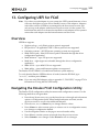
UEFIBoot for NIC, iSCSI, and FCoE adapters in x64 systems. This provides
system boot capability through the use of the UEFI (Unified Extensible
Firmware Interface) Shell. It also functions on UEFI 2.x-based platforms
through the HII (Human Interface Infrastructure) interface.
OpenBoot for FCoE and NIC adapters in Sun SPARC systems (OpenBoot is also
called FCode). For more information, see chapter 4., “Configuring Boot from
SAN for the FCoE Protocol,” on page 67 and appendix I., “Booting the Solaris
Operating System from the Network on SPARC Systems,” on page 312.
Note: Emulex drivers support multipath boot configurations. See your storage
vendor's documentation for information on configuring multipath booting.
The Emulex boot code and the following utilities provide a variety of capabilities:
Boot from SAN across the different networking protocols and operating
systems
UEFI configuration using the Emulex NIC, FCoE, and iSCSI Configuration
Utilities
PXESelect Utility
Configuring the port and controller
Configuring multichannel support and personality options
FCoE Boot BIOS Utility
Scanning for target devices
Boot Version 10.2 for NIC, iSCSI, FCoE, and RoCE Protocols User Manual
P010097-01B Rev. A
20
1. Introduction
Abbreviations
Configuring boot devices and advanced adapter parameters
iSCSISelect Utility
Setting up a basic configuration
Configuring and managing iSCSI initiators and targets
The boot code is distributed in the same image used to flash the firmware. Several
methods are available for flashing the firmware and boot code image. See the
documentation accompanying each utility for additional information on the flash
procedure.
Abbreviations
ACL
Access Control List
AL_PA
Arbitrated Loop Physical Address
API
application programming interface
ARI
alternative routing-ID interpretation
ARP
Address Resolution Protocol
BBS
BIOS Boot Specification
BFS
boot from SAN
BIOS
basic input/output system
BOFM
Blade Open Firmware Management Protocol
CEE
Converged Enhanced Ethernet
CHAP
Challenge Handshake Authentication Protocol
CLI
command line interface
DCB
Data Center Bridging
DCBX
Data Center Bridging Exchange Protocol
DHCP
Dynamic Host Configuration Protocol
DID
device ID
DMA
direct memory access
DNS
Domain Name System
EDD
Enhanced Disk Device
EFI
Extensible Firmware Interface
FC
Fibre Channel
FC-AL
Fibre Channel Arbitrated Loop
FCF
FC Forwarder
FCoE
Fibre Channel over Ethernet
FL_Port
fabric loop port
FMP
Firmware Management Protocol
FoD
Feature on Demand
Boot Version 10.2 for NIC, iSCSI, FCoE, and RoCE Protocols User Manual
P010097-01B Rev. A
21
1. Introduction
Abbreviations
FTP
File Transfer Protocol
FUI
FoD Unique Identifier
Gb/s
gigabits per second
GPT
GUID partition table
GUI
graphic user interface
GUID
Globally Unique Identifier
HBA
host bus adapter
HII
Human Interface Infrastructure
HTTP
Hypertext Transfer Protocol
IEEE
Institute of Electrical and Electronics Engineers
iBFT
iSCSI boot firmware table
INTx
PCIe legacy interrupts, where “x” is variable
I/O
input/output
IOCTL
input/output control
IP
internet protocol
IQN
iSCSI qualified name
iSCSI
Internet Small Computer System Interface
JBOD
just a bunch of disks
KB
1024 bytes (Kilobyte or Kibibyte)
LACP
Link Aggregation Control Protocol
LDAP
Lightweight Directory Access Protocol
LED
light-emitting diode
LOM
LAN on motherboard
LPVID
logical port VLAN ID
LUN
logical unit number
MAC
media access control
MBR
master boot record
MPIO
multipath I/O
MSI
message signaled interrupts
MSI-X
message signaled interrupts - extended
MTU
maximum transmission unit
NBP
network bootstrap program
NIC
network interface card (or controller)
NIS/NIS+
Network Information Service/Network Information Service Plus
NIV
Network Interface Virtualization
NLB
network loopback
NPAR
NIC partitioning
Boot Version 10.2 for NIC, iSCSI, FCoE, and RoCE Protocols User Manual
P010097-01B Rev. A
22
1. Introduction
Abbreviations
NPIV
N_Port ID virtualization
NVRAM
non-volatile random-access memory
OCM
OneCommand Manager
OEM
original equipment manufacturer
OS
operating system
PCI
Peripheral Component Interconnect
PCIe
Peripheral Component Interconnect Express
PDU
protocol data unit
PF
physical function
PLOGI
port login
POST
power on self test
PXE
Preboot eXecution Environment
QoS
quality of service
RAID
redundant array of independent disks
RDMA
remote direct memory access
RHEL
Red Hat Enterprise Linux
RIS
Remote Installation Services
RoCE
RDMA over Converged Ethernet
ROM
read-only memory
RPM
resource package manager
RSS
receive side scaling
SAN
storage area network
SCSI
Small Computer System Interface
SLES
SUSE Linux Enterprise Server
SLI
Service Level Interface
SNP
Simple Network Protocol
SR-IOV
single root I/O virtualization
SVID
service VLAN ID
TB
terabyte
TCP
transmission control protocol
TFTP
Trivial File Transfer Protocol
UCM
Universal Configuration Manager
UCNA
universal converged network adapter
UDP
User Datagram Protocol
UFP
Unified Fabric Protocol
UEFI
Unified Extensible Firmware Interface
UMC
universal multichannel
Boot Version 10.2 for NIC, iSCSI, FCoE, and RoCE Protocols User Manual
P010097-01B Rev. A
23
1. Introduction
Abbreviations
UNDI
Universal Network Device Interface
USB
Universal Serial Bus
VF
virtual function
VLAN
virtual local area network
VM
virtual machine
VMQ
virtual machine queue
vNIC
virtual NIC
WDS
Windows Deployment Services
WWN
world wide name
WWNN
world wide node name
WWPN
world wide port name
x
Used to designate a variable. For example, SPx includes SP1, SP2, etc.
ZB
zettabyte
Boot Version 10.2 for NIC, iSCSI, FCoE, and RoCE Protocols User Manual
P010097-01B Rev. A
24
2. Configuring PXE Boot for NIC on LPe16202, OCe10100, and OCe11100-series Adapters
Pre-OS
2. Configuring PXE Boot for NIC on LPe16202,
OCe10100, and OCe11100-series Adapters
Note: This section applies to LPe16202, OCe10100, and OCe11100-series adapters. See
chapter 3., “Configuring PXE Boot for NIC on OCe14000-series Adapters,” on
page 43 for information specific to those adapters.
Note: The LPe16202 adapter may be reported as an OCe15100 adapter by certain
applications.
This section describes using and configuring PXE to boot computers using a network
interface independent of available data storage devices (such as hard disks) or installed
operating systems.
The PXE protocol is a combination of DHCP and TFTP with subtle modifications to
both. DHCP locates the appropriate boot server or servers, and TFTP downloads the
initial bootstrap program and additional files.
Network booting enables you to perform the following tasks:
Boot diskless systems such as thin clients and dedicated systems.
Deploy software and operating systems for your systems.
Automate system maintenance, such as backups.
Automate system checking, such as virus scanning.
Ensure a system is secure.
Pre-OS
PXE can be used in a “pre-OS” environment. Pre-OS is the process of loading a small
operating environment to perform a client management task before loading the final
operating system from the local hard drive. For example, with a pre-OS you can scan
the hard drive for viruses. This guarantees that the client is not infected before it starts.
The WDS uses this to install operating systems on local disks or BFS disks.
PXE Boot Process
Once PXE Boot is enabled in the system UEFI/BIOS, the PXE client can boot up and
start up the PXE boot ROM. This is the boot code physically located on the NIC
adapter.
Note: To enable or disable PXE Boot, it must be enabled or disabled in the system
UEFI/BIOS; see the documentation that accompanied the server for more
information.
Boot Version 10.2 for NIC, iSCSI, FCoE, and RoCE Protocols User Manual
P010097-01B Rev. A
25
2. Configuring PXE Boot for NIC on LPe16202, OCe10100, and OCe11100-series Adapters
PXE Boot Process
Figure 2-1 PXE Boot Process
Figure 2-1 shows the boot process.
1. The PXE boot ROM sends a DHCP request extended with PXE specific options (step
1 in the figure).
2. The DHCP responses contain the DHCP options (DHCPOFFERs) that include the
NBP filename and boot server lists (steps 2 through 5).
3. The PXE client attempts to download the specified NBP over TFTP from one of the
specified boot servers (steps 6 and 7).
4. The PXE client executes the downloaded NBP (steps 8 and 9).
Note: If any of these steps fail, the boot process typically continues using the next
available device in the boot sequence, depending on the system configuration
and boot order.
Boot Version 10.2 for NIC, iSCSI, FCoE, and RoCE Protocols User Manual
P010097-01B Rev. A
26
2. Configuring PXE Boot for NIC on LPe16202, OCe10100, and OCe11100-series Adapters
Remotely Installing with PXE for Windows Server 2008, 2008 R2, 2012, and 2012 R2
Remotely Installing with PXE for Windows Server
2008, 2008 R2, 2012, and 2012 R2
For remote installation with PXE, a network driver for the Emulex adapter must be part
of the client's installation image on the server. The current versions of Windows Server
2008 and Windows Server 2008 R2 do not include network drivers for the Emulex
adapter; however, Windows Server 2012 and 2012 R2 include the network driver for
the Emulex adapter.
To add the image and installation using the driver with the Remote Installation Service
Setup, select:
Start Menu > Programs > Administrative Tools Remote Installation Services
Setup
(For more information, refer to Microsoft Article ID Q246184 - How to Add Third-Party
OEM Network Adapters to RIS Installations.)
In addition to the network driver for the Emulex adapter, you must configure the
following services to use PXE for remote installations:
DHCP server
Remote Installation Services
Windows Deployment Services
Microsoft provides extensive documentation on deploying its operating systems for
remote installations, and different setups may be required depending on your
individual implementation. Microsoft provides step-by-step guides for its Windows
Deployment Services for configuring your server, adding images, and installing an
operating system. It also includes instructions for more advanced tasks like creating
multicast transmissions, creating custom images, and performing an unattended
installation.
For detailed information on deploying and managing remote installations on Windows
Server 2008, Windows Server 2008 R2, Windows Server 2012, and Windows Server
2012 R2, see the Microsoft website and visit Microsoft TechNet. Search on the bulleted
terms above to access Microsoft's wide-ranging documentation on these subjects.
Remotely Installing with PXE for Linux and Citrix
Servers
Linux allows for PXE installation over a network using the NFS, TFTP, or HTTP
protocols. If the system to be installed contains an Emulex NIC or adapter with PXE
Boot support, it can be configured to boot from files on another networked system
rather than local media.
The Linux distributions provide extensive documentation on deploying and managing
remote installations of the Linux operating system via PXE. See your appropriate
distribution's documentation for instructions on how to deploy a PXE installation over
your network.
Boot Version 10.2 for NIC, iSCSI, FCoE, and RoCE Protocols User Manual
P010097-01B Rev. A
27
2. Configuring PXE Boot for NIC on LPe16202, OCe10100, and OCe11100-series Adapters
Using the PXESelect Utility
For remote installation with PXE, a network driver for the Emulex adapter must be part
of the client's installation image on the server. Your current Linux distribution may or
may not include network drivers for Emulex adapters. If they do, the driver may need
to be added to your operating system’s installation image, or added during installation.
See your appropriate distribution's documentation for instructions on how to add
drivers during installation.
Using the PXESelect Utility
Note: If you are using Dell adapters, refer to appendix G., “Configuring PXE Boot for
NIC on Dell OCe10100-based Systems,” on page 293 for information on using
the PXESelect utility.
Navigating the PXESelect Utility
Use the following methods to navigate the PXESelect utility:
Press the up/down arrows on your keyboard to move through and select menu
options or configuration fields. When multiple adapters are listed, use the
up/down arrows to scroll to the additional adapters.
Press <Tab> to move to the next field or to select a row in a configuration
screen. Use <Shift> <Tab> to move to the previous field.
Press <Enter> to accept a selection, select a menu option, or to change a
configuration default.
Press <Esc> to return to the previous menu or page, cancel a selection or dialog
box, or exit the utility.
Running the PXESelect Utility
To run the PXESelect utility, start or restart your computer. When prompted, hold
down <Ctrl> and press <P>. If you are running the PXESelect utility with multiple
controllers, all your controllers are displayed when you start the utility. For example:
Press <Ctrl><P> for PXESelect(TM)Utility
Controller#0 Port#0 Base 0xFCE60000 at Bus:05 Dev:00 Fun:00
Controller#0 Port#1 Base 0xFCEA0000 at Bus:05 Dev:00 Fun:01
Controller#1 Port#0 Base 0xFC920000 at Bus:01 Dev:00 Fun:00
Controller#1 Port#1 Base 0xFC960000 at Bus:01 Dev:00 Fun:01
- Initializing ...Done.
The PXE Configuration menu appears after the boot BIOS initializes to begin your PXE
configuration.
Note: A UEFI-capable system typically does not display the prompt for running the
PXESelect utility unless it is configured for legacy booting. See your system
configuration manual for information on performing a legacy boot. All
configuration that can be performed in the PXESelect utility can instead be
Boot Version 10.2 for NIC, iSCSI, FCoE, and RoCE Protocols User Manual
P010097-01B Rev. A
28
2. Configuring PXE Boot for NIC on LPe16202, OCe10100, and OCe11100-series Adapters
Using the PXESelect Utility
performed in the UEFI configuration utility. See chapter 11., “Configuring UEFI
for Ethernet,” on page 134 for more information.
Setting Up a PXE Bootable Network
After the PXE boot BIOS initializes, you can use the PXESelect utility to set up a PXE
bootable network by configuring your controllers.
To configure controllers for PXE boot:
1. At the Controller Selection Menu, use the <Tab> key to select the controller you
want to configure and press <Enter>.
Figure 2-2 Controller Selection Menu
Note: The Controller Selection Menu only appears if there are two or more
adapters connected.
The Controller Configuration menu appears.
Figure 2-3 Controller Configuration Menu
Depending on the adapter, one or more of the following options will be displayed:
MultiChannel Mode – when multichannel is enabled, you can access up to eight
virtual network interfaces.
For additional information on Multichannel Mode, see “Configuring Universal
Multichannel” on page 37.
Note: If you are using an IBM adapter, see “Configuring Multichannel for IBM
Adapters” on page 39 for additional information on Multichannel Mode.
Note: A reboot will occur when you exit the PXESelect utility if the
Multichannel Mode has changed since the last boot.
Advanced Mode Support – Advanced Mode support is enabled by default on
OCe11100-series 2-port and 4-port controllers and the LPe16202/OCe15100
converged fabric adapter (CFA). Advanced Mode support enables you to run
Advanced Mode-aware drivers that provide advanced capabilities. For
additional information on configuring Advanced Mode, see “Advanced Mode
Support” on page 32.
Note: On 4-port controllers, the Advanced Mode setting is not provided in the
PXESelect utility.
Boot Version 10.2 for NIC, iSCSI, FCoE, and RoCE Protocols User Manual
P010097-01B Rev. A
29
2. Configuring PXE Boot for NIC on LPe16202, OCe10100, and OCe11100-series Adapters
Using the PXESelect Utility
Personality – This option specifies a list of available protocols that can be
configured on an adapter. For additional information on adapter personality,
see “Personality Option” on page 30.
Note: Changing the Personality setting requires a reboot before the change
will take effect. A reboot will occur when you exit the PXESelect utility if
the Personality setting has changed since the last boot.
2. Once you have set the options in the Controller Configuration menu, select Save
and press <Enter>.
3. To proceed, select Continue and press <Enter>.
The Port Selection Menu appears.
4. Select the port you want to configure and press <Enter>.
Figure 2-4 Port Selection Menu
Note: The Port Selection Menu only appears if there are two or more ports
connected.
Depending on your installed adapter and the Multichannel Mode setting, proceed
to the following sections:
If Multichannel Mode is disabled, or it is not supported, refer to
“Configuring Ports When Multichannel is Disabled or Not Supported” on
page 34 for additional configuration information.
If Multichannel Mode is enabled, refer to “Configuring Universal
Multichannel” on page 37 for additional configuration information.
If Multichannel Mode is enabled and you are using IBM adapters, refer to
“Configuring Multichannel for IBM Adapters” on page 39 for additional
configuration information.
Personality Option
The “personality” reflects the protocol, or protocols, of the adapter. This option
specifies a list of available protocols that can be configured on an adapter. Depending
on the personalities for which the adapter is licensed, one of the following selections
appears:
NIC
iSCSI
FCoE
Custom
The menu only displays the available personalities, including both free and licensed
personalities.
Boot Version 10.2 for NIC, iSCSI, FCoE, and RoCE Protocols User Manual
P010097-01B Rev. A
30
2. Configuring PXE Boot for NIC on LPe16202, OCe10100, and OCe11100-series Adapters
Using the PXESelect Utility
The NIC personality implies that all the enabled functions provide NIC/TOE
functionality.
Note: TOE is not supported on LPe16202/OCe15000-series adapters.
iSCSI and FCoE personalities are enabled on one function per adapter port and include
NIC functionality on the other enabled functions. There can be only one storage
protocol on each port.
For information about custom personalities, see “Configuring the Custom Personality
Selection” on page 31.
To select the personality of the adapter:
1. From the Controller Configuration menu, use the <Tab> key to select Personality
and a pop-up menu appears.
Figure 2-5 Controller Configuration Menu – Personality Selection
2. Select NIC, iSCSI, FCoE, or Custom and press <Enter>.
3. Select Save and press <Enter>.
Note: Changing the Personality setting requires a reboot before the change will
take effect. A reboot will occur when you exit the PXESelect utility if the
Personality setting has changed since the last boot.
Configuring the Custom Personality Selection
The Custom personality allows you to select the protocol type for each function (0–7).
iSCSI and FCoE personalities may only be enabled on one function per adapter port.
Note: There cannot be two iSCSI functions and two FCoE functions on a single port.
To select the Custom personality:
1. From the Controller Configuration menu, use the <Tab> key to select Personality
and a pop-up menu appears.
2. Select Custom and press <Enter>.
Boot Version 10.2 for NIC, iSCSI, FCoE, and RoCE Protocols User Manual
P010097-01B Rev. A
31
2. Configuring PXE Boot for NIC on LPe16202, OCe10100, and OCe11100-series Adapters
Using the PXESelect Utility
3. If multichannel is enabled, on the Multichannel Configuration screen select the
specific function and press <Enter>. A pop-up menu is displayed.
Figure 2-6 Custom Personality Selection on Multichannel Configuration Screen
Note: If multichannel is disabled, on the Port Configuration screen select the
specific function and press <Enter>. A pop-up menu is displayed.
4. Select the desired personality for the appropriate function and press <Enter>.
As mentioned previously for the Custom personality, iSCSI and FCoE personalities
may only be enabled on one function per adapter port.
5. Select Save and press <Enter>.
Note: Changing the Personality setting requires a reboot before the change will
take effect. A reboot will occur when you exit the PXESelect utility if the
Personality setting has changed since the last boot.
Advanced Mode Support
Advanced Mode is a driver compatibility option. With Advanced Mode enabled, you
can run Advanced Mode-aware drivers that provide advanced capabilities as listed in
Table 2-1. With Advanced Mode disabled, you can run older legacy inbox drivers that
are not Advanced Mode-aware with the latest firmware versions.
Note: Advanced Mode support is enabled by default on OCe11100-series 2-port and
4-port controllers and the LPe16202/OCe15100 CFA. On 4-port controllers, the
Advanced Mode setting is not provided in the PXESelect/HII utilities. The
Advanced Mode setting on these platforms is implicitly enabled and Advanced
Mode-aware drivers must be installed. Compatibility with legacy drivers
requires that Advanced Mode support be disabled on 2-port controllers.
Boot Version 10.2 for NIC, iSCSI, FCoE, and RoCE Protocols User Manual
P010097-01B Rev. A
32
2. Configuring PXE Boot for NIC on LPe16202, OCe10100, and OCe11100-series Adapters
Using the PXESelect Utility
Note: Advanced Mode is not supported on OCe10100-series controllers.
Table 2-1 Advanced Mode Capabilities (by Operating System)
Operating System
Advanced Mode Enabled
Advanced Mode Disabled
(Legacy Mode)
Windows
16 RSS queues
4 RSS Queues
Note: Only supported on Windows
Server 2008 R2, 2012, and 2012
R2. Remains four queues for
earlier Windows versions.
VMQ lookahead split
Note: VMQs are only supported on
Windows Server 2008 R2 and
later versions.
Linux and Citrix
16 RSS Queues
Lookahead split is silently ignored.
There may be a small performance
penalty for VMQs.
4 RSS Queues
VFs/PFs can be increased up to 30
VMware ESXi
For both 1500 and 9000 MTU:
16 NetQueues/PFs in non-VFA
4 NetQueues/PFs in VFA
1500 MTU – 8 NetQueues/PFs in
non-VFA and 4 NetQueues/PFs in VFA.
9000 MTU – 4 NetQueues/PFs in both
VFA and non-VFA
To configure Advanced Mode support:
1. From the Controller Configuration menu, use the <Tab> key to select Advanced
Mode Support and a pop-up menu appears.
Figure 2-7 Controller Configuration Menu – Advanced Mode Support Selection
2. Select Enabled or Disabled and press <Enter>.
3. Select Save and press <Enter>.
Boot Version 10.2 for NIC, iSCSI, FCoE, and RoCE Protocols User Manual
P010097-01B Rev. A
33
2. Configuring PXE Boot for NIC on LPe16202, OCe10100, and OCe11100-series Adapters
Using the PXESelect Utility
Configuring Ports When Multichannel is Disabled or Not
Supported
Note: If your adapter has multichannel enabled, refer to “Configuring Universal
Multichannel” on page 37. If you are using an IBM adapter, refer to
“Configuring Multichannel for IBM Adapters” on page 39.
If Multichannel Mode is disabled, or if it is not supported, the Port Configuration
screen appears after you select a port in the Port Selection Menu.
Figure 2-8 Port Configuration Screen
Note: Logical Link Status is displayed as “N/A” for storage functions.
The Port Configuration screen enables you to perform the following tasks:
Configure PXE boot support
Configure SR-IOV
Configure PXE VLAN ID and Priority
Identify ports
Erase the port and adapter configuration
Configuring PXE Boot Support
To configure PXE boot support:
1. On the configuration screen, use the <Tab> key to select the PXE Boot Support
setting and a pop-up menu appears.
2. Select Enabled or Disabled and press <Enter>.
3. Select Save and press <Enter>.
Note: During system startup, PXE contacts the DHCP server for an IP address to
boot from the network.
Boot Version 10.2 for NIC, iSCSI, FCoE, and RoCE Protocols User Manual
P010097-01B Rev. A
34
2. Configuring PXE Boot for NIC on LPe16202, OCe10100, and OCe11100-series Adapters
Using the PXESelect Utility
Configuring SR-IOV
If your system BIOS supports SR-IOV, you can enable it on the adapter. SR-IOV
support can only be enabled when multichannel is disabled or not supported. For more
information on SR-IOV configuration, see the appropriate Emulex driver manual.
To configure SR-IOV:
1. On the configuration screen, use the <Tab> key to select the SR-IOV setting and a
pop-up menu appears.
2. Select Enabled or Disabled and press <Enter>.
3. Select Save and press <Enter>.
Configuring the PXE VLAN ID and Priority
To configure a PXE VLAN ID and set the priority level:
1. On the configuration screen, select Configure PXE VLAN ID/Priority and press
<Enter>. The Configure PXE VLAN ID/Priority menu is displayed.
Figure 2-9 Configure PXE VLAN ID/Priority Menu
2. Use the <Tab> key to select the PXE VLAN Support setting and a pop-up menu
appears.
a. For PXE VLAN Support, select Enabled and press <Enter>.
b. For the PXE VLAN ID, enter a number from 0-4094 and press <Enter>.
c. For the PXE VLAN Priority level, enter a number from 0-7 and press <Enter>.
This unique value assigns a priority to outbound packets containing a specified
VLAN ID. Valid values range from 0-7, with 0 the highest priority level.
3. Select Save and press <Enter>.
After you exit the PXESelect utility, the system will reboot for the configuration to take
effect.
Boot Version 10.2 for NIC, iSCSI, FCoE, and RoCE Protocols User Manual
P010097-01B Rev. A
35
2. Configuring PXE Boot for NIC on LPe16202, OCe10100, and OCe11100-series Adapters
Using the PXESelect Utility
Physically Identifying the Port
To physically determine which port you are configuring by causing the link and
activity LEDs of that port to blink:
1. On the configuration screen, select Port Identification and press <Enter>. The Port
Identification screen appears.
Figure 2-10 Port Identification Screen
2. The LEDs on your controller begin blinking. The selected port’s LED status
indicators blink on your controller until you select Done on this screen and press
<Enter>.
Note: Not all controllers have LEDs that are visible externally. If you are using an
add-in card in a blade server environment, the port identification or beaconing
capability does not work.
Erasing Ports and Controller Configuration
Note: When this setting is selected, all previous configuration settings are returned to
their factory default settings except for the current personality selection. Emulex
recommends performing this action to provide a clean environment for new
configuration settings to take effect.
To erase the ports and controller configuration:
1. On the configuration screen, select Erase Configuration and press <Enter>. A
warning appears asking if you want to erase the current configuration for all ports
of the controller.
2. Press <Y> to delete the configuration. You will receive another warning asking you
to confirm the permanent removal of the controller configuration.
3. Press <Y> to delete the configuration.
To exit the PXESelect utility after erasing the ports and controller configuration:
1. Follow the instructions on the bottom of the individual menu screens until you are
prompted to exit.
2. Press <Y> to exit. Depending on the settings that were changed, a reboot may be
necessary.
Note: For older systems, depending on the memory allocation method supported,
the PXESelect utility automatically reboots even when there are no changes
made to the system.
Boot Version 10.2 for NIC, iSCSI, FCoE, and RoCE Protocols User Manual
P010097-01B Rev. A
36
2. Configuring PXE Boot for NIC on LPe16202, OCe10100, and OCe11100-series Adapters
Using the PXESelect Utility
Configuring Universal Multichannel
Note: UMC support is only available on OCe11100-series adapters.
Note: If your adapter has multichannel enabled and also supports IBM Virtual Fabric
Mode or IBM Unified Fabric Protocol Mode, refer to “Configuring Multichannel
for IBM Adapters” on page 39 for additional information. If multichannel is
disabled or not supported on the adapter, refer to “Configuring Ports When
Multichannel is Disabled or Not Supported” on page 34.
UMC provides the ability to configure multiple physical functions or I/O channels for
each physical adapter port. For additional information on UMC support, see the Emulex
Universal Multichannel Reference Guide.
Note: When UMC is enabled, you must configure the multichannel settings
(minimum and maximum bandwidths) for iSCSI and FCoE storage functions in
the NIC BIOS before they can be configured further from their respective
utilities (iSCSI or FCoE BIOS). Otherwise, the Logical Link for that function will
still show as down, and you will not be able to log into targets or find LUNs
behind those targets.
Note: Multichannel functionality is only supported on OneConnect adapters running
in 10 Gb mode. The 1 Gb mode does not support UMC.
To view the MultiChannel Configuration screen:
1. From Port Selection Menu (Figure 2-4), select the port you want to configure and
press <Enter>. The MultiChannel Configuration screen appears.
Figure 2-11 MultiChannel Configuration Screen
Notes:
Logical Link Status is displayed as “N/A” for storage functions.
SR-IOV support can only be enabled if UMC support is disabled.
If your system does not support some of the multichannel options, those
unavailable options appear as N/A on the MultiChannel Configuration screen.
Boot Version 10.2 for NIC, iSCSI, FCoE, and RoCE Protocols User Manual
P010097-01B Rev. A
37
2. Configuring PXE Boot for NIC on LPe16202, OCe10100, and OCe11100-series Adapters
Using the PXESelect Utility
2. From the MultiChannel Configuration screen, you can perform the following tasks:
Configure PXE boot support – see “Configuring PXE Boot Support” on page 34
for instructions.
Configure PXE VLAN ID/Priority – see “Configuring the PXE VLAN ID and
Priority” on page 35 for instructions.
Identify ports – see “Physically Identifying the Port” on page 36 for instructions.
Erase the port and adapter configuration – see “Erasing Ports and Controller
Configuration” on page 36 for instructions.
Configure the minimum and maximum bandwidth for each channel.
Configure the LPVID for each channel.
Note: Your adapter or system may not support all multichannel options.
Configuring Minimum and Maximum Bandwidth
To configure bandwidth:
1. On the configuration screen, use the <Tab> key to select Minimum Bandwidth or
Maximum Bandwidth.
The Minimum Bandwidth value is the least amount of bandwidth that the
function can provide. It is represented as a percentage. The Minimum
Bandwidth value must be less than or equal to the Maximum Bandwidth value.
The total of the Minimum Bandwidth values for all enabled functions on that
port must be equal to 100.
Note: A Minimum Bandwidth value of 0 is a valid value. When all of the
partitions’ Minimum Bandwidth values are zero, the bandwidth is
distributed equally among the current active partitions. If a specific
partition’s Minimum Bandwidth and Maximum Bandwidth values are
0, that partition’s logical link will be brought down.
The Maximum Bandwidth value is the greatest amount of bandwidth that the
function can provide. It is represented as a percentage.
2. Enter the value for the specified option and press <Enter>.
3. Select Save and press <Enter>.
Configuring LPVID
The LPVID is used to enforce a VLAN ID on all traffic originating from an IP address,
channel, or PCI function. If the operating system for that PCI function has set up a
VLAN ID, then the operating system-configured VLAN ID takes precedence over the
LPVID for transmit packets while the operating system-configured VLAN ID and
LPVID-tagged packets will both be received. If the operating system has not set up any
VLAN IDs, then the LPVID is used for tagging.
Note: LPVID and user-configured VLAN IDs from the operating system must be
different.
Note: LPVIDs also need to be configured on the switch port.
Boot Version 10.2 for NIC, iSCSI, FCoE, and RoCE Protocols User Manual
P010097-01B Rev. A
38
2. Configuring PXE Boot for NIC on LPe16202, OCe10100, and OCe11100-series Adapters
Using the PXESelect Utility
Each LPVID must be unique and is relevant for NIC traffic only. The LPVID is not
supported for storage functions. For iSCSI storage functions, you must configure a
VLAN ID through iSCSISelect or through the host. For additional information, see
“Configuring VLAN ID and VLAN Priority” on page 113.
During PXE boot when the UNDI Driver (BIOS) is functional, the PXE VLAN is used.
However, once the NIC driver is operational the LPVID is used.
Note: If no PXE VLAN is configured, the LPVID is used.
For example:
PXE Install OS
PXE Server configured with VLAN 5
PXE VLAN=5
LPVID for function 0=5
To configure LPVID:
1. On the configuration screen, use the <Tab> key to select LPVID and a dialog box
appears.
2. Enter a value and press <Enter>. The LPVID range is 2-4094. A value of 0 disables
the LPVID.
3. Select Save and press <Enter>.
Configuring Multichannel for IBM Adapters
Note: This section only pertains to certain Emulex OneConnect adapters that support
IBM Virtual Fabric multichannel or Unified Fabric Protocol.
When you want to enable multichannel on IBM adapters, you must select a
Multichannel Mode.
To select the Multichannel Mode:
1. From the Controller Configuration menu, use the <Tab> key to select the
Multichannel Mode setting and a pop-up menu appears.
Figure 2-12 Controller Configuration Screen - IBM Adapters
2. Select one of the following settings and press <Enter>:
Switch Independent Mode
IBM Virtual Fabric Mode
IBM Unified Fabric Protocol Mode
Disabled
Boot Version 10.2 for NIC, iSCSI, FCoE, and RoCE Protocols User Manual
P010097-01B Rev. A
39
2. Configuring PXE Boot for NIC on LPe16202, OCe10100, and OCe11100-series Adapters
Using the PXESelect Utility
Note: For more information on the available Multichannel Modes, see
“Multichannel Modes”.
3. Select Save and press <Enter>.
4. To proceed, select Continue and press <Enter>.
With the Multichannel Mode selected, you can now configure multichannel support.
See “Multichannel Configuration” for more information.
Multichannel Modes
Note: The following modes are only available on IBM adapters and systems that
support IBM Virtual Fabric and Unified Fabric Protocol modes.
An IBM Virtual Fabric-enabled switch provides the ability to configure an LPVID for a
virtual channel or I/O channel on an adapter port. If multichannel is supported on
your system, the PXESelect utility enables you to select one of the following modes:
IBM Virtual Fabric Mode – select this mode when a OneConnect adapter is
attached to an IBM Virtual Fabric-enabled switch.
IBM Unified Fabric Protocol Mode – select this mode when a OneConnect
adapter is attached to an IBM UFP-enabled switch.
Note: Some IBM switches support both UFP and IBM Virtual Fabric Mode.
Switch Independent Mode – select this mode if you are using a switch other
than an IBM Virtual Fabric or UFP-enabled switch. When this mode is enabled,
refer to “Configuring Universal Multichannel” on page 37 for information on
configuring multichannel.
Note: Multichannel functionality is only supported on OneConnect adapters running
in 10 Gb mode. The 1 Gb mode does not support multichannel.
Multichannel Configuration
Multichannel provides the ability to configure multiple PCI functions or I/O channels
for each physical adapter port.
Note: Setting up IBM Virtual Fabric or UFP multichannel depends on cooperation
with adjacent switches.
Note: Refer to “Configuring Universal Multichannel” on page 37 for information on
configuring multichannel when Switch Independent mode is enabled.
To view the configuration screen:
1. From Port Selection Menu (Figure 2-4), select the port you want to configure and
press <Enter>. The configuration screen appears.
When configuring multichannel on adapters that support IBM Virtual Fabric and
UFP modes, the configuration screen will depend on the Multichannel Mode that
has been selected.
Boot Version 10.2 for NIC, iSCSI, FCoE, and RoCE Protocols User Manual
P010097-01B Rev. A
40
2. Configuring PXE Boot for NIC on LPe16202, OCe10100, and OCe11100-series Adapters
Using the PXESelect Utility
Note: For illustration purposes, the screen displays in this section are for a system
with IBM Virtual Fabric Mode enabled.
Figure 2-13 IBM Virtual Fabric Mode Configuration Screen
Notes:
Logical Link Status is displayed as “N/A” for storage functions.
SR-IOV support can only be enabled if multichannel support is disabled.
If your system does not support some of the multichannel options, those
unavailable options are displayed as N/A on the MultiChannel Configuration
screen.
The SVID, or Outer VLAN ID, is displayed in IBM Virtual Fabric Mode and IBM
Unified Fabric Protocol Mode. This value is provided by the IBM switch and
will appear when the protocol modes are configured on the switch and the
adapter. If the protocol modes are not configured, a value of “N/A” is
displayed.
2. From the configuration screen, you can perform the following tasks:
Configure PXE boot support – see “Configuring PXE Boot Support” on page 34
for instructions.
Configure PXE VLAN ID/Priority – see “Configuring the PXE VLAN ID and
Priority” on page 35 for instructions.
Identify ports – see “Physically Identifying the Port” on page 36 for instructions.
Erase the port and adapter configuration – see “Erasing Ports and Controller
Configuration” on page 36 for instructions.
Configure the LPVID for each channel – see “Configuring LPVID” on page 38
for instructions.
Note: An LPVID is optional for IBM Virtual Fabric Mode, but it is required for
every function when using Switch Independent Mode.
Note: When IBM Virtual Fabric Mode or Unified Fabric Protocol Mode is enabled, you
must configure the minimum and maximum bandwidth settings on the switch.
Boot Version 10.2 for NIC, iSCSI, FCoE, and RoCE Protocols User Manual
P010097-01B Rev. A
41
2. Configuring PXE Boot for NIC on LPe16202, OCe10100, and OCe11100-series Adapters
PXE Boot Parameters Default Values
PXE Boot Parameters Default Values
The default settings for the PXE Boot parameters are listed in the following table.
Table 2-2 PXE Boot Parameter Default Values
Parameter
Default Value
Valid Values
Advanced Mode
Enabled (OCe11100-series 2-port and
4-port controllers and the
LPe16202/OCe15100 CFA)
Enabled
Disabled
Disabled (OCe10100-series controllers)
PXE Boot Support
SR-IOV
The default for this parameter varies
depending on the vendor
configuration.
Enabled
Disabled
Enabled
Disabled
Disabled
VLAN Support
Disabled
Enabled
Disabled
VLAN ID
0
0–4094
VLAN Priority
0
0–7
Multichannel Mode
The default for this parameter varies
depending on the vendor
configuration.
For Emulex adapters:
• Enabled
• Disabled
For IBM adapters:
• IBM Virtual Fabric Mode
• IBM Unified Fabric Protocol Mode
• Switch Independent Mode
• Disabled
Minimum Bandwidth
0%
Must have a total of 100% across all
ports.
Maximum Bandwidth
0%
From the minimum bandwidth value up
to 100% (inclusive).
LPVID
0
2–4094
Boot Version 10.2 for NIC, iSCSI, FCoE, and RoCE Protocols User Manual
P010097-01B Rev. A
42
3. Configuring PXE Boot for NIC on OCe14000-series Adapters
Pre-OS
3. Configuring PXE Boot for NIC on
OCe14000-series Adapters
Note: This section applies only to OCe14000-series adapters. See chapter 2.,
“Configuring PXE Boot for NIC on LPe16202, OCe10100, and OCe11100-series
Adapters,” on page 25 for information specific to those adapters.
This section describes using and configuring PXE to boot computers using a network
interface independent of available data storage devices (such as hard disks) or installed
operating systems.
The PXE protocol is a combination of DHCP and TFTP with subtle modifications to
both. DHCP locates the appropriate boot server or servers, and TFTP downloads the
initial bootstrap program and additional files.
Network booting enables you to perform the following tasks:
Boot diskless systems such as thin clients and dedicated systems.
Deploy software and operating systems for your systems.
Automate system maintenance, such as backups.
Automate system checking, such as virus scanning.
Ensure a system is secure.
Pre-OS
PXE can be used in a “pre-OS” environment. Pre-OS is the process of loading a small
operating environment to perform a client management task before loading the final
operating system from the local hard drive. For example, with a pre-OS you can scan
the hard drive for viruses. This guarantees that the client is not infected before it starts.
The WDS uses this to install operating systems on local disks or BFS disks.
PXE Boot Process
Once PXE Boot is enabled in the system UEFI/BIOS, the PXE client can boot up and
start up the PXE boot ROM. This is the boot code physically located on the NIC
adapter.
Note: To enable or disable PXE Boot, it must be enabled or disabled in the system
UEFI/BIOS; see the documentation that accompanied the server for more
information.
Boot Version 10.2 for NIC, iSCSI, FCoE, and RoCE Protocols User Manual
P010097-01B Rev. A
43
3. Configuring PXE Boot for NIC on OCe14000-series Adapters
PXE Boot Process
Figure 3-1 PXE Boot Process
Figure 3-1 shows the boot process.
1. The PXE boot ROM sends a DHCP request extended with PXE specific options (step
1 in the figure).
2. The DHCP responses contain the DHCP options (DHCPOFFERs) that include the
NBP filename and boot server lists (steps 2 through 5).
3. The PXE client attempts to download the specified NBP over TFTP from one of the
specified boot servers (steps 6 and 7).
4. The PXE client executes the downloaded NBP (steps 8 and 9).
Note: If any of these steps fail, the boot process typically continues using the next
available device in the boot sequence, depending on the system configuration
and boot order.
Boot Version 10.2 for NIC, iSCSI, FCoE, and RoCE Protocols User Manual
P010097-01B Rev. A
44
3. Configuring PXE Boot for NIC on OCe14000-series Adapters
Remotely Installing with PXE for Windows Server 2008, 2008 R2, 2012, and 2012 R2
Remotely Installing with PXE for Windows Server
2008, 2008 R2, 2012, and 2012 R2
For remote installation with PXE, a network driver for the Emulex adapter must be part
of the client's installation image on the server. The current versions of Windows Server
2008 and Windows Server 2008 R2 do not include network drivers for the Emulex
adapter; however, Windows Server 2012 and 2012 R2 include the network driver for
the Emulex adapter.
To add the image and installation using the driver with the Remote Installation Service
Setup, select:
Start Menu > Programs > Administrative Tools Remote Installation Services
Setup
(For more information, refer to Microsoft Article ID Q246184 - How to Add Third-Party
OEM Network Adapters to RIS Installations.)
In addition to the network driver for the Emulex adapter, you must configure the
following services to use PXE for remote installations:
DHCP server
Remote Installation Services
Windows Deployment Services
Microsoft provides extensive documentation on deploying its operating systems for
remote installations, and different setups may be required depending on your
individual implementation. Microsoft provides step-by-step guides for its Windows
Deployment Services for configuring your server, adding images, and installing an
operating system. It also includes instructions for more advanced tasks like creating
multicast transmissions, creating custom images, and performing an unattended
installation.
For detailed information on deploying and managing remote installations on Windows
Server 2008, Windows Server 2008 R2, Windows Server 2012, and Windows Server
2012 R2, see the Microsoft website and visit Microsoft TechNet. Search on the bulleted
terms above to access Microsoft's wide-ranging documentation on these subjects.
Remotely Installing with PXE for Linux and Citrix
Servers
Linux allows for PXE installation over a network using the NFS, TFTP, or HTTP
protocols. If the system to be installed contains an Emulex NIC or adapter with PXE
Boot support, it can be configured to boot from files on another networked system
rather than local media.
The Linux distributions provide extensive documentation on deploying and managing
remote installations of the Linux operating system via PXE. See your appropriate
distribution's documentation for instructions on how to deploy a PXE installation over
your network.
Boot Version 10.2 for NIC, iSCSI, FCoE, and RoCE Protocols User Manual
P010097-01B Rev. A
45
3. Configuring PXE Boot for NIC on OCe14000-series Adapters
Using the PXESelect Utility
For remote installation with PXE, a network driver for the Emulex adapter must be part
of the client's installation image on the server. Your current Linux distribution may or
may not include network drivers for Emulex adapters. If they do, the driver may need
to be added to your operating system’s installation image, or added during installation.
See your appropriate distribution's documentation for instructions on how to add
drivers during installation.
Using the PXESelect Utility
Note: If you are using Dell OCe14000-based adapters, refer to appendix H.,
“Configuring PXE Boot for NIC on Dell OCe14000-based Systems,” on page 300
for information on using the PXESelect utility.
Navigating the PXESelect Utility
Use the following methods to navigate the PXESelect utility:
Press the up or down arrows on your keyboard to move through and select
menu options or configuration fields. When multiple adapters are listed, use the
up/down arrows to scroll to the additional adapters.
Press the left or right arrows on your keyboard to move through and select
setting options.
Press <Enter> to accept a selection, select a menu option, or to change a
configuration default.
Press <F7> to save the changes on the screen.
Press <Esc> to return to the previous menu or page, cancel a selection or dialog
box, or exit the utility.
Running the PXESelect Utility
To run the PXESelect utility, start or restart your computer. When prompted, hold
down <Ctrl> and press <P>. If you are running the PXESelect utility with multiple
controllers, all your controllers are displayed when you start the utility. For example:
Press <Ctrl><P> for PXESelect(TM)Utility
Controller#0 Port#0 Base 0xFCE60000 at Bus:05 Dev:00 Fun:00
Controller#0 Port#1 Base 0xFCEA0000 at Bus:05 Dev:00 Fun:01
Controller#1 Port#0 Base 0xFC920000 at Bus:01 Dev:00 Fun:00
Controller#1 Port#1 Base 0xFC960000 at Bus:01 Dev:00 Fun:01
- Initializing ...Done.
The PXE Configuration menu appears after the boot BIOS initializes to begin your PXE
configuration.
Note: A UEFI-capable system typically does not display the prompt for running the
PXESelect utility unless it is configured for legacy booting. See your system
configuration manual for information on performing a legacy boot. All
Boot Version 10.2 for NIC, iSCSI, FCoE, and RoCE Protocols User Manual
P010097-01B Rev. A
46
3. Configuring PXE Boot for NIC on OCe14000-series Adapters
Using the PXESelect Utility
configuration that can be performed in the PXESelect utility can instead be
performed in the UEFI configuration utility. See chapter 11., “Configuring UEFI
for Ethernet,” on page 134 for more information.
Setting Up a PXE Bootable Network
After the PXE boot BIOS initializes, you can use the PXESelect utility to set up a PXE
bootable network by configuring your controllers.
To configure controllers for PXE boot:
1. From the Controller List screen, use the up or down arrow keys to select the
controller you want to configure and press <Enter>.
Figure 3-2 Controller List Screen
Note: The Controller List screen only appears if there are two or more adapters
connected.
The Configure Controller screen appears.
Figure 3-3 Configure Controller Screen
Depending on the adapter, one or more of the following items are displayed:
Controller Name – displays the controller’s name.
Firmware Version – displays the current firmware version.
IPL Version – displays the IPL version.
MultiChannel – when multichannel is enabled, you can access up to 16 virtual
network interfaces.
For additional information on multichannel, see “Configuring
Multichannel” on page 56.
Note: If you are using an IBM adapter, see “Configuring Multichannel for
IBM Adapters” on page 62 for additional information.
Boot Version 10.2 for NIC, iSCSI, FCoE, and RoCE Protocols User Manual
P010097-01B Rev. A
47
3. Configuring PXE Boot for NIC on OCe14000-series Adapters
Using the PXESelect Utility
Note: On HP systems, you can select either Disable or Flex-10 for the
MultiChannel setting. When Flex-10 is selected, the settings are
display only and cannot be configured.
Note: A reboot will occur when you exit the PXESelect utility if the
multichannel mode has changed since the last boot.
Personality – This option specifies a list of available protocols that can be
configured on an adapter. For additional information on adapter personality,
see “Configuring Personality” on page 49.
Note: Changing the Personality setting requires a reboot before the change
will take effect. A reboot will occur when you exit the PXESelect utility if
the Personality setting has changed since the last boot.
SRIOV – if your system BIOS supports SR-IOV, you can enable it when
multichannel is disabled or it is not supported. For more information on SR-IOV
configuration, see “Configuring SR-IOV” on page 50.
RoCE Profile – This setting is only available when the Personality is set to
“NIC+RoCE”. For more information, see “Configuring Personality” on page 49.
NIC Mode – This setting is only available when SR-IOV is enabled, Personality
is set to “NIC”, and a two-port OCe14000-series adapter is in use. For more
information, see “Configuring Personality” on page 49.
2. Once you have set the options in the Configure Controller screen, press <F7> to
save the current settings.
3. Press <F6> to proceed.
Note: If you want to erase the current configuration, press <F8>. See “Erasing
Ports and Controller Configuration” on page 55 for more information.
The Port Selection Menu appears.
Figure 3-4 Port Selection Menu
Note: The Port Selection Menu only appears if there are two or more ports
connected.
4. Select the port you want to configure and press <Enter>. The Port Menu appears.
Depending on your installed adapter and the MultiChannel setting, proceed to the
following sections:
If multichannel is disabled, or it is not supported, refer to “Configuring
Ports When Multichannel is Disabled or Not Supported” on page 49 for
additional configuration information.
Boot Version 10.2 for NIC, iSCSI, FCoE, and RoCE Protocols User Manual
P010097-01B Rev. A
48
3. Configuring PXE Boot for NIC on OCe14000-series Adapters
Using the PXESelect Utility
If multichannel is enabled, refer to “Configuring Multichannel” on page 56
for additional configuration information.
If multichannel is enabled and you are using IBM adapters, refer to
“Configuring Multichannel for IBM Adapters” on page 62 for additional
configuration information.
Configuring Ports When Multichannel is Disabled or Not
Supported
Note: If your adapter has multichannel enabled, refer to “Configuring Multichannel”
on page 56. If you are using an IBM adapter, refer to “Configuring Multichannel
for IBM Adapters” on page 62.
Configuring Personality
The “personality” reflects the protocol, or protocols, of the adapter. This option
specifies a list of available protocols that can be configured on an adapter. Depending
on the personalities for which the adapter is licensed one or more of the following
selections may appear:
NIC – implies that all the enabled functions provide NIC functionality
iSCSI or FCoE – these personalities are enabled on one function per adapter port
and include NIC functionality on the other enabled functions. There can be only
one of each storage protocol on each port.
NIC+RoCE – implies that all the enabled functions provide RoCE functionality.
When NIC+RoCE is enabled, the RoCE Profile selection is available.
Note: When SR-IOV is enabled, the NIC+RoCE personality setting is
unavailable.
Note: RoCE is supported on Windows only.
The menu only displays the available personalities, including both free and licensed
personalities.
Note: There cannot be two iSCSI functions and two FCoE functions on a single port.
To select the personality of the adapter:
1. From the Configure Controller screen, use the up or down arrow keys to select
Personality.
Boot Version 10.2 for NIC, iSCSI, FCoE, and RoCE Protocols User Manual
P010097-01B Rev. A
49
3. Configuring PXE Boot for NIC on OCe14000-series Adapters
Using the PXESelect Utility
Use the left or right arrow keys to select the desired personality.
Figure 3-5 Configure Controller Screen – Personality Selection
2. Press <F7> to save.
Note: Changing the Personality setting requires a reboot before the change will
take effect. A reboot will occur when you exit the PXESelect utility if the
Personality setting has changed since the last boot.
Configuring the RoCE Profile
Note: The RoCE Profile setting is only available when the NIC+RoCE personality is
selected.
The RoCE profile allows you to select the appropriate profile for your particular system
setup. The RoCE profile choices include:
RoCE-1 – For the RoCE-1 profile, check the Implementer's Lab on the Emulex
website for any updated information on use cases for the RoCE-1 profile.
RoCE-2 – Choose the RoCE-2 profile for SMB Direct on Windows Server 2012
and Windows Server 2012 R2.
To select a RoCE Profile:
1. From the Configure Controller screen, ensure that the NIC+RoCE personality is
selected.
2. Use the up or down arrow keys to select RoCE Profile.
3. Use the left or right arrow keys to select the desired profile and press <Enter>.
4. Press <F7> to save.
Configuring SR-IOV
If your system BIOS supports SR-IOV, you can enable it on the adapter. SR-IOV
support can only be enabled when multichannel is disabled or not supported.
Note: When SR-IOV is enabled, the NIC+RoCE personality setting is unavailable.
To configure SR-IOV:
1. From the Configure Controller screen, use the up or down arrow keys to select
SRIOV.
Boot Version 10.2 for NIC, iSCSI, FCoE, and RoCE Protocols User Manual
P010097-01B Rev. A
50
3. Configuring PXE Boot for NIC on OCe14000-series Adapters
Using the PXESelect Utility
2. Use the left or right arrow keys to enable or disable SRIOV.
3. Press <F7> to save.
For more information on SR-IOV configuration, see the appropriate Emulex driver
manual.
Configuring NIC Mode
Note: This setting is only available when SR-IOV is enabled, Personality is set to
“NIC”, and a two-port OCe14000-series adapter is in use.
This setting allows you to control the VF count on a two-port OCe14000-series adapter.
The choices include:
NIC – the VF count is restricted to 31 VFs per port and QoS is supported for
those VFs.
NIC-ETS Disabled – the VF count is set to 63 VFs per port but QoS is not
supported for those VFs.
To select the NIC Mode:
1. From the Configure Controller screen (Figure 3-5), ensure that the NIC personality
is selected and SR-IOV is enabled.
2. Use the up or down arrow keys to select NIC Mode.
3. Use the left or right arrow keys to select the desired setting and press <Enter>.
4. Press <F7> to save.
Loading Default Settings
If you want to erase the current configuration, from the Configure Controller screen
press <F8>.
See “Erasing Ports and Controller Configuration” on page 55 for more information.
Selecting a Port
Once you have set the options in the Configure Controller screen, ensure that you have
saved your changes. To save the current settings, press <F7>.
To proceed to the Port Selection menu:
1. From the Configure Controller screen, press <F6>. The Port Selection Menu
appears.
Figure 3-6 Port Selection Menu
Note: The Port Selection Menu only appears if there are two or more ports
connected.
Boot Version 10.2 for NIC, iSCSI, FCoE, and RoCE Protocols User Manual
P010097-01B Rev. A
51
3. Configuring PXE Boot for NIC on OCe14000-series Adapters
Using the PXESelect Utility
2. Select the port you want to configure and press <Enter>. The Port Menu appears.
Figure 3-7 Port Menu Screen
The Port Menu screen enables you to perform the following tasks:
View NIC configuration information – see “Viewing NIC Configuration
Information” on page 52 for additional information.
Configure boot options – see “Configuring Boot Options” on page 53 for
instructions.
Configure port options – see “Configuring Port Options” on page 54 for
instructions.
Viewing NIC Configuration Information
To view the NIC configuration information:
1. From the Port Menu screen, use the up or down arrow keys to select 1. NIC
Configuration and press <Enter>. Depending on the currently selected Personality
setting, one of the following screens will appear.
If the Personality setting is set to iSCSI or FCoE, the Channel(s) List screen
appears.
Figure 3-8 Channel(s) List Screen
Select a channel using the up or down arrow keys and press <Enter>. The
Configure Channel screen appears.
Boot Version 10.2 for NIC, iSCSI, FCoE, and RoCE Protocols User Manual
P010097-01B Rev. A
52
3. Configuring PXE Boot for NIC on OCe14000-series Adapters
Using the PXESelect Utility
If the Personality setting is set to NIC or NIC+RoCE, the Configure Channel
screen appears.
Figure 3-9 Configure Channel Screen
2. From the Configure Channel screen, you can view the following information:
Function number
Protocol
Minimum BW (Min BW)
Maximum BW (Max BW)
Permanent and virtual MAC addresses
Logical link status
Assigned LPVID
SRIOV status
Configuring Boot Options
To view the Boot Configuration screen:
1. From the Port Menu (Figure 3-7), select 2. Boot Configuration and press <Enter>.
The Boot Configuration screen appears.
Figure 3-10 Boot Configuration Screen
From the Boot Configuration screen, you can configure PXE boot support.
Configuring PXE Boot Support
To configure PXE boot support:
1. On the Boot Configuration screen, use the left or right arrow keys to enable or
disable the PXE Boot setting.
2. Press <F7> to save.
Note: During system startup when PXE boot is enabled, PXE contacts the DHCP
server for an IP address to boot from the network.
Boot Version 10.2 for NIC, iSCSI, FCoE, and RoCE Protocols User Manual
P010097-01B Rev. A
53
3. Configuring PXE Boot for NIC on OCe14000-series Adapters
Using the PXESelect Utility
Configuring Port Options
To view the Port Configuration screen:
1. From the Port Menu (Figure 3-7), select 3. Port Configuration and press <Enter>.
The Port Configuration screen appears.
Figure 3-11 Port Configuration Screen
2. From the Port Configuration screen, you can perform the following tasks:
View the physical link speed and link status.
Configure PXE VLAN, including the PXE VLAN ID and priority – see
“Configuring PXE VLAN” on page 54 for instructions.
Identify the port – see “Physically Identifying the Port” on page 55 for
instructions.
Configuring PXE VLAN
To enable PXE VLAN:
1. On the Port Configuration screen, use the up or down arrow keys to highlight the
current PXE VLAN setting.
2. Use the left or right arrow keys to enable the PXE VLAN setting.
3. Press <F7> to save.
To configure a PXE VLAN ID:
1. On the Port Configuration screen, use the up or down arrow keys to highlight the
current PXE VLAN ID setting.
2. Use the left or right arrow keys to enter a number from 1-4094.
3. Press <F7> to save.
To set the priority level:
1. On the Port Configuration screen, use the up or down arrow keys to highlight the
current PXE VLAN Priority setting.
2. Use the left or right arrow keys to enter a number from 0-7.
This unique value assigns a priority to outbound packets containing a specified
VLAN ID. Valid values range from 0-7, with 0 being the highest priority level.
3. Press <F7> to save.
After you exit the PXESelect utility, the system will reboot for the configuration to take
effect.
Boot Version 10.2 for NIC, iSCSI, FCoE, and RoCE Protocols User Manual
P010097-01B Rev. A
54
3. Configuring PXE Boot for NIC on OCe14000-series Adapters
Using the PXESelect Utility
Physically Identifying the Port
To physically determine which port you are configuring by causing the link and
activity LEDs of that port to blink:
1. On the Port Configuration screen, press <F5>.
2. The LEDs on your controller begin blinking. The selected port’s LED status
indicators blink on your controller for approximately 15 seconds.
Note: Not all controllers have LEDs that are visible externally. If you are using an
add-in card in a blade server environment, the port identification or beaconing
capability does not work.
Erasing Ports and Controller Configuration
Note: When this setting is selected, all previous configuration settings are returned to
their factory default settings except for the current personality selection. Emulex
recommends performing this action to provide a clean environment for new
configuration settings to take effect.
To erase the ports and controller configuration:
1. On the Configure Controller screen (Figure 3-3), press <F8> to restore the factory
default settings. A warning appears asking if you want to erase the current
configuration for all ports of the controller.
2. Press <Y> to delete the configuration. You will receive another warning asking you
to confirm the permanent removal of the controller configuration.
3. Press <Y> to delete the configuration.
To exit the PXESelect utility after erasing the ports and controller configuration:
1. Follow the instructions on the bottom of the individual menu screens until you are
prompted to exit.
2. Press <Y> to exit. Depending on the settings that were changed, a reboot may be
necessary.
Note: For older systems, depending on the memory allocation method supported,
the PXESelect utility automatically reboots even when there are no changes
made to the system.
Boot Version 10.2 for NIC, iSCSI, FCoE, and RoCE Protocols User Manual
P010097-01B Rev. A
55
3. Configuring PXE Boot for NIC on OCe14000-series Adapters
Using the PXESelect Utility
Configuring Multichannel
Note: If your adapter has multichannel enabled and also supports IBM Virtual Fabric
Mode or IBM Unified Fabric Protocol Mode, refer to “Configuring Multichannel
for IBM Adapters” on page 62 for additional information. If multichannel is
disabled or not supported on the adapter, refer to “Configuring Ports When
Multichannel is Disabled or Not Supported” on page 49.
Enabling Multichannel
Multichannel, or UMC, provides the ability to configure multiple physical functions or
I/O channels for each physical adapter port. For additional information on
multichannel support, see the Emulex Universal Multichannel Reference Guide.
Notes:
When multichannel is enabled, you must configure the multichannel settings
(minimum and maximum bandwidths) for iSCSI and FCoE storage functions in
the NIC BIOS before they can be configured further from their respective
utilities (iSCSI or FCoE BIOS). Otherwise, the Logical Link for that function will
still show as down, and you will not be able to log into targets or find LUNs
behind those targets.
Multichannel functionality is only supported on OneConnect adapters running
in 10 Gb or 40 Gb mode. The 1 Gb mode does not support multichannel.
SR-IOV is not available when multichannel is enabled.
To enable multichannel:
1. From the Configure Controller screen, use the up or down arrow keys to select
MultiChannel.
2. Use the left or right arrow keys to enable multichannel.
Figure 3-12 Configure Controller Screen – MultiChannel Enabled
3. Press <F6> to proceed.
Boot Version 10.2 for NIC, iSCSI, FCoE, and RoCE Protocols User Manual
P010097-01B Rev. A
56
3. Configuring PXE Boot for NIC on OCe14000-series Adapters
Using the PXESelect Utility
ARI Support
The OCe14000-series adapters support ARI, which provides the ability to configure
additional PCI functions or I/O channels for each physical adapter port when
multichannel is enabled.
You can configure up to 16 functions on a one-port OCe14400-series adapter, up to
eight functions per port on a one or two-port OCe14100-series adapter, and up to four
functions per port on a four-port OCe14100-series adapter.
The maximum number of functions allowed on an adapter is controlled by the
adapter's IPL file and the system’s support for ARI.
The following requirements must be met in order to support more than eight functions
on an adapter.
The system hardware (the motherboard and BIOS) must support ARI.
ARI must be enabled in the system BIOS.
The host operating system must support ARI:
Windows Server 2012 and newer versions
RHEL 6.4 and newer versions
SLES 11 SP2 and newer versions
ESXi 5.0 and newer versions
The application management tools, including the OneCommand Manager
application must support ARI.
ARI must be enabled in the firmware using the OneCommand Manager
application.
If these conditions are not met, you may be able to configure more than eight functions,
but only up to eight functions will be running and discovered after a reboot.
Configuring Personality
The “personality” reflects the protocol, or protocols, of the adapter. This option
specifies a list of available protocols that can be configured on an adapter. Depending
on the personalities for which the adapter is licensed, one or more of the following
selections appears:
NIC – implies that all the enabled functions provide NIC functionality
iSCSI or FCoE – these personalities are enabled on one function per adapter port
and include NIC functionality on the other enabled functions. There can be only
one of each storage protocol on each port.
Note: There cannot be two iSCSI functions and two FCoE functions on a single
port.
Custom – for information about custom personalities, see “Configuring the
Custom Personality Selection” on page 58.
The menu only displays the available personalities, including both free and licensed
personalities.
Boot Version 10.2 for NIC, iSCSI, FCoE, and RoCE Protocols User Manual
P010097-01B Rev. A
57
3. Configuring PXE Boot for NIC on OCe14000-series Adapters
Using the PXESelect Utility
To select the personality of the adapter:
1. From the Configure Controller screen (Figure 3-12), use the up or down arrow keys
to select Personality.
2. Use the left or right arrow keys to select the desired personality.
3. Press <F7> to save.
Note: Changing the Personality setting requires a reboot before the change will
take effect. A reboot will occur when you exit the PXESelect utility if the
Personality setting has changed since the last boot.
Configuring the Custom Personality Selection
The Custom personality allows you to select the protocol type for each function. The
first function on the port must always be assigned the NIC personality. iSCSI and FCoE
personalities may only be enabled on one function per adapter port.
Note: There cannot be two iSCSI functions and two FCoE functions on a single port.
To select the Custom personality:
1. From the Configure Controller screen, use the up or down arrow keys to select
Personality.
2. Use the left or right arrow keys to select the Custom personality and press <Enter>.
A pop-up menu is displayed.
3. Select the desired personality for the appropriate function using the arrow keys.
As mentioned previously for the Custom personality, iSCSI and FCoE personalities
may only be enabled on one function per adapter port.
4. Press <F7> to save.
Note: Changing the Personality setting requires a reboot before the change will
take effect. A reboot will occur when you exit the PXESelect utility if the
Personality setting has changed since the last boot.
Loading Default Settings
If you want to erase the current configuration, from the Configure Controller screen,
press <F8>.
See “Erasing Ports and Controller Configuration” on page 55 for more information.
Boot Version 10.2 for NIC, iSCSI, FCoE, and RoCE Protocols User Manual
P010097-01B Rev. A
58
3. Configuring PXE Boot for NIC on OCe14000-series Adapters
Using the PXESelect Utility
Selecting a Port
Once you have set the options in the Configure Controller screen, ensure that you have
saved your changes. To save the current settings, press <F7>.
To proceed to the Port Selection menu:
1. From the Configure Controller screen, press <F6>. The Port Selection Menu
appears.
Figure 3-13 Port Selection Menu
Note: The Port Selection Menu only appears if there are two or more ports
connected.
2. Use the up or down arrow keys to select the port you want to configure and press
<Enter>. The Port Menu appears.
Figure 3-14 Port Menu Screen
The Port Menu screen enables you to perform the following tasks:
Configure multichannel options – see “Configuring Multichannel Options” on
page 60 for instructions.
Configure boot options – see “Configuring Boot Options” on page 53 for
instructions.
Configure port options – see “Configuring Port Options” on page 54 for
instructions.
Boot Version 10.2 for NIC, iSCSI, FCoE, and RoCE Protocols User Manual
P010097-01B Rev. A
59
3. Configuring PXE Boot for NIC on OCe14000-series Adapters
Using the PXESelect Utility
Configuring Multichannel Options
To configure the multichannel options:
1. From the Port Menu screen, use the up or down arrow keys to select
1. MultiChannel Configuration and press <Enter>. The Channel(s) List screen
appears.
Figure 3-15 Channels List Screen
2. Select a channel using the up or down arrow keys and press <Enter>. The
Configure Channel screen appears.
Figure 3-16 Configure Channel Screen
3. From the Configure Channel screen, you can perform the following tasks:
View the function number.
Select the protocol for each function, except for PF #0 and PF #1. See
“Configuring Personality” on page 57 for instructions.
Configure the minimum and maximum bandwidth for each channel. See
“Configuring Minimum and Maximum Bandwidth” on page 61 for
instructions.
View the permanent and virtual MAC addresses.
View the logical link status.
Note: Logical Link Status is displayed as “N/A” for storage functions.
Configure the LPVID for each channel. For more information, see “Configuring
LPVID” on page 61.
View the SR-IOV status.
Boot Version 10.2 for NIC, iSCSI, FCoE, and RoCE Protocols User Manual
P010097-01B Rev. A
60
3. Configuring PXE Boot for NIC on OCe14000-series Adapters
Using the PXESelect Utility
Note: SR-IOV is automatically disabled when multichannel is enabled.
Note: Your adapter or system may not support all multichannel options.
Configuring Minimum and Maximum Bandwidth
To configure bandwidth:
1. On the Configure Channel screen, use the use the up or down arrow keys to select
Min BW or Max BW.
2. Use the left or right arrow keys to select the desired bandwidth value.
The Minimum Bandwidth value is the least amount of bandwidth that the
function can provide. It is represented as a percentage. The Minimum
Bandwidth value must be less than or equal to the Maximum Bandwidth value.
The total of the Minimum Bandwidth values for all enabled functions on that
port must be equal to 100.
Note: A Minimum Bandwidth value of 0 is a valid value. When all of the
partitions’ Minimum Bandwidth values are zero, the bandwidth is
distributed equally among the current active partitions. If a specific
partition’s Minimum Bandwidth and Maximum Bandwidth values are
0, that partition’s logical link will be brought down.
The Maximum Bandwidth value is the greatest amount of bandwidth that the
function can provide. It is represented as a percentage.
3. Press <F7> to save.
Configuring LPVID
The LPVID is used to enforce a VLAN ID on all traffic originating from an IP address,
channel, or PCI function. If the operating system for that PCI function has set up a
VLAN ID, then the operating system-configured VLAN ID takes precedence over the
LPVID for transmit packets while the operating system-configured VLAN ID and
LPVID-tagged packets will both be received. If the operating system has not set up any
VLAN IDs, then the LPVID is used for tagging.
Note: LPVID and user-configured VLAN IDs from the operating system must be
different.
Note: LPVIDs must be configured on the switch port.
Each LPVID must be unique and is relevant for NIC traffic only. The LPVID is not
supported for storage functions. For iSCSI storage functions, you must configure a
VLAN ID through iSCSISelect or through the host. For additional information, see
“Configuring VLAN ID and VLAN Priority” on page 113.
During PXE boot when the UNDI Driver (BIOS) is functional, the PXE VLAN is used.
However, once the NIC driver is operational the LPVID is used.
Note: If no PXE VLAN is configured, the LPVID is used.
For example:
Boot Version 10.2 for NIC, iSCSI, FCoE, and RoCE Protocols User Manual
P010097-01B Rev. A
61
3. Configuring PXE Boot for NIC on OCe14000-series Adapters
Using the PXESelect Utility
PXE Install OS
PXE Server configured with VLAN 5
PXE VLAN=5
LPVID for function 0=5
To configure LPVID:
1. On the Configure Channel screen, use the use the up or down arrow keys to select
LPVID.
2. Use the left or right arrow keys to select the desired LPVID value. The LPVID range
is 2-4094. A value of 0 disables the LPVID.
3. Press <F7> to save.
Configuring Multichannel for IBM Adapters
Note: This section only pertains to certain Emulex OneConnect adapters that support
IBM Virtual Fabric multichannel or Unified Fabric Protocol.
When you want to enable multichannel on IBM adapters, you must select a
Multichannel Mode.
To select the Multichannel Mode:
1. From the Controller Configuration screen, use the up or down arrow keys to select
the Multichannel Mode setting.
Figure 3-17 Controller Configuration Screen - IBM Adapters
2. Use the left or right arrow keys to select one of the following settings and press
<Enter>:
Switch Independent Mode
IBM Virtual Fabric Mode
IBM Unified Fabric Protocol Mode
Disabled
Note: For more information on the available Multichannel Modes, see
“Multichannel Modes”.
3. Press <F6> to proceed.
Boot Version 10.2 for NIC, iSCSI, FCoE, and RoCE Protocols User Manual
P010097-01B Rev. A
62
3. Configuring PXE Boot for NIC on OCe14000-series Adapters
Using the PXESelect Utility
With the Multichannel Mode selected, you can now configure multichannel support.
See “Multichannel Configuration” for more information.
Multichannel Modes
Note: The following modes are only available on IBM adapters and systems that
support IBM Virtual Fabric and Unified Fabric Protocol modes.
An IBM Virtual Fabric-enabled switch provides the ability to configure an LPVID for a
virtual channel or I/O channel on an adapter port. If multichannel is supported on
your system, the PXESelect utility enables you to select one of the following modes:
IBM Virtual Fabric Mode – select this mode when a OneConnect adapter is
attached to an IBM Virtual Fabric-enabled switch.
IBM Unified Fabric Protocol Mode – select this mode when a OneConnect
adapter is attached to an IBM UFP-enabled switch.
Note: Some IBM switches support both UFP and IBM Virtual Fabric Mode.
Switch Independent Mode – select this mode if you are using a switch other
than an IBM Virtual Fabric or UFP-enabled switch. When this mode is enabled,
refer to “Configuring Multichannel” on page 56 for information on configuring
multichannel.
Note: Multichannel functionality is only supported on OneConnect adapters running
in 10 Gb mode. The 1 Gb mode does not support multichannel.
Multichannel Configuration
Multichannel provides the ability to configure multiple PCI functions or I/O channels
for each physical adapter port.
Note: Setting up IBM Virtual Fabric or UFP multichannel depends on cooperation
with adjacent switches.
Note: Refer to “Configuring Multichannel” on page 56 for information on configuring
multichannel when Switch Independent mode is enabled.
To view the configuration screen:
1. From Port Selection Menu (Figure 3-13), select the port you want to configure and
press <Enter>. The configuration screen appears.
When configuring multichannel, the configuration options will depend on the
Multichannel Mode that has been selected.
Boot Version 10.2 for NIC, iSCSI, FCoE, and RoCE Protocols User Manual
P010097-01B Rev. A
63
3. Configuring PXE Boot for NIC on OCe14000-series Adapters
Using the PXESelect Utility
Note: For illustration purposes, the screen displays in this section are for a system
with the IBM Virtual Fabric Mode multichannel mode selected.
Figure 3-18 IBM Virtual Fabric Mode MultiChannel Configuration Screen
Note: If your system does not support some of the multichannel options, those
unavailable options are disabled on the MultiChannel Configuration screen.
2. From the MultiChannel Configuration screen, you can perform the following tasks:
View the function number.
Select the protocol for each function, except for PF #0 and PF #1. See
“Configuring Personality” on page 57 for instructions.
Note: The Custom personality is not supported on IBM adapters and systems.
Configure the minimum and maximum bandwidth for each channel. See
“Configuring Minimum and Maximum Bandwidth” on page 61 for
instructions.
Note: When Switch Independent Mode is enabled, you must configure the
minimum and maximum bandwidth settings on the switch.
View the permanent and virtual MAC addresses.
View the logical link status.
Note: Logical Link Status is displayed as “N/A” for storage functions.
Configure the LPVID for each channel. For more information, see “Configuring
LPVID” on page 61.
Note: An LPVID is optional for IBM Virtual Fabric Mode, but it is required for
every function when using Switch Independent Mode.
View the SR-IOV status.
Note: SR-IOV is automatically disabled when multichannel is enabled.
Boot Version 10.2 for NIC, iSCSI, FCoE, and RoCE Protocols User Manual
P010097-01B Rev. A
64
3. Configuring PXE Boot for NIC on OCe14000-series Adapters
PXE Boot Parameters Default Values
PXE Boot Parameters Default Values
The default settings for the PXE Boot parameters are listed in the following table.
Table 3-1 PXE Boot Parameter Default Values
Parameter
Default Value
Valid Values
Multichannel
The default for this parameter varies
depending on the vendor
configuration.
For Emulex adapters:
• Enabled
• Disabled
For IBM adapters:
• IBM Virtual Fabric Mode
• IBM Unified Fabric Protocol Mode
• Switch Independent Mode
• Disabled
Personality
The default for this parameter varies
depending on the vendor
configuration.
When multichannel is enabled:
• NIC
• iSCSI
• FCoE
• Custom
When multichannel and SR-IOV are
disabled:
• NIC
• iSCSI
• FCoE
• NIC+RoCE
Note: RoCE is supported on Windows
only.
When multichannel is disabled and
SR-IOV is enabled:
• NIC
• iSCSI
• FCoE
SR-IOV
Disabled
Enabled
Disabled
RoCE Profile
RoCE-1
RoCE-1
RoCE-2
Note: This setting is
only available
when the
NIC+RoCE
personality is
selected.
Minimum Bandwidth
0%
Must have a total of 100% across all
ports.
Maximum Bandwidth
0%
From the minimum bandwidth value up
to 100% (inclusive).
LPVID
0
2–4094
Boot Version 10.2 for NIC, iSCSI, FCoE, and RoCE Protocols User Manual
P010097-01B Rev. A
65
3. Configuring PXE Boot for NIC on OCe14000-series Adapters
PXE Boot Parameters Default Values
Table 3-1 PXE Boot Parameter Default Values (Continued)
Parameter
Default Value
Valid Values
PXE Boot Support
The default for this parameter varies
depending on the vendor
configuration.
Enabled
Disabled
Enabled
PXE VLAN
Disabled
Disabled
PXE VLAN ID
0
0–4094
PXE VLAN Priority
0
0–7
Boot Version 10.2 for NIC, iSCSI, FCoE, and RoCE Protocols User Manual
P010097-01B Rev. A
66
4. Configuring Boot from SAN for the FCoE Protocol
Windows Server 2008, Windows Server 2012, and Windows Server 2012 R2
4. Configuring Boot from SAN for the FCoE
Protocol
When booting from SAN, the storage device is typically identified by its WWPN and a
LUN. By extending the server system BIOS, boot from SAN capability is provided by
the boot BIOS contained on an Emulex adapter in the server. When properly
configured, the adapter then permanently directs the server to boot from a logical unit
(disk) on the SAN as if it were a local disk.
Note: Not all procedures are required. Emulex adapters usually ship from the factory
with the latest version of boot code installed and enabled, so you do not need to
install or enable boot code in those cases. However, if boot code is not enabled,
you must enable it. You may want to update the boot code if a more current
version is available on the Emulex website at http://www.emulex.com.
This section describes how to set up a system to boot from SAN. This specific procedure
to follow is determined by the system architecture and the operating system.
Windows Server 2008, Windows Server 2012, and
Windows Server 2012 R2
Configuring Boot from SAN on Windows (x64)
To configure boot from SAN:
1. If necessary, update the boot code on the adapter. See chapter 7., “Updating and
Enabling Boot Code,” on page 104 for more information.
2. If necessary, enable the boot code on the adapter. See chapter 7., “Updating and
Enabling Boot Code,” on page 104 for more information.
3. Enable the adapter to boot from SAN. See “Enabling an Adapter to Boot from SAN”
on page 88 for more information.
4. Configure boot devices. See “Configuring Boot Devices” on page 90 for more
information.
5. If desired, configure the boot options on the adapter. See “Configuring Advanced
Adapter Parameters” on page 93 for more information.
6. Install the operating system on a boot disk.
For additional information, see “Installing Windows Server 2008, 2008 R2, 2012, or
2012 R2 on a Boot Disk (x64)” on page 70.
Boot Version 10.2 for NIC, iSCSI, FCoE, and RoCE Protocols User Manual
P010097-01B Rev. A
67
4. Configuring Boot from SAN for the FCoE Protocol
Windows Server 2008, Windows Server 2012, and Windows Server 2012 R2
Configuring Boot from SAN on Windows (UEFI)
To configure boot from SAN:
1. If necessary, update the boot code on the adapter. See chapter 7., “Updating and
Enabling Boot Code,” on page 104 for more information.
2. If necessary, enable the boot code on the adapter. See “Enabling an Adapter to Boot
from SAN” on page 88 for more information.
3. Configure boot devices. See “Configuring Boot Devices” on page 90 for more
information.
4. If desired, configure the boot options on the adapter. See “Configuring Advanced
Adapter Parameters” on page 93 for more information.
5. Install the operating system on a boot disk:
For a new installation of a UEFI-aware operating system on a UEFI-based x64
server, see “Installing a New Windows UEFI-aware Operating System on a
UEFI-based x64 Server” on page 68.
For Windows Server 2008, 2012, or 2012 R2, see “Installing Windows Server
2008, 2008 R2, 2012, or 2012 R2 on a Boot Disk (x64)” on page 70.
Installing a New Windows UEFI-aware Operating System on
a UEFI-based x64 Server
This installation procedure assumes LUNs are created in the SAN storage device and
zoned appropriately to the host adapter's WWN.
To install a new Windows Server UEFI-aware operating system:
1. From the server system UEFI setup, ensure that CD/DVD is the first device in the
Boot Order list.
2. Enable the adapter BIOS setting to allow SAN boot in the Emulex UEFI
configuration utility.
3. Configure the boot target and LUN in Emulex UEFI configuration utility to select
the desired target.
4. Boot the host server with the Windows Server 2008, 2008 R2, 2012, or 2012 R2 DVD
inserted. Follow the on-screen prompts to install the appropriate version of
Windows Server.
5. The Windows installation exposes all available/visible LUNs as disks and
partitions numbered 0 to N, where N is the highest number available. These
numbers typically are the LUN numbers assigned by the array.
6. Select the disk on which you want to install the operating system.
7. Follow system prompts in the Windows installation.
Note: The operating system image is installed with the GPT disk partition. See
“GUID Partition Table” on page 69 for a brief description of GPT disk
partitions.
8. After the installation is complete, a boot option variable called Windows Boot
Manager is populated with a media device path pointing to the Windows boot
Boot Version 10.2 for NIC, iSCSI, FCoE, and RoCE Protocols User Manual
P010097-01B Rev. A
68
4. Configuring Boot from SAN for the FCoE Protocol
Windows Server 2008, Windows Server 2012, and Windows Server 2012 R2
loader utility. Windows Boot Manager can be found in the Start Options menu of
the Host Server UEFI.
9. The Windows Boot Manager option is inserted as the first boot option in the boot
order list of the Host Server UEFI. The CD/DVD boot is the second device in the
boot order list.
10. Upon reboot, the system boots from the LUN set up on the SAN.
Directing a UEFI-based Server to a Windows Server 2008,
2008 R2, 2012, or 2012 R2 Operating System Image
(Installed as UEFI-aware) Already Installed on the SAN
This installation procedure assumes a LUN exists in the SAN storage device, is zoned
appropriately to the host adapter’s WWN, and a UEFI-aware operating system resides
on the target LUN.
To direct a UEFI-based server to a Windows Server operating system image:
1. Enable network boot in the Emulex UEFI configuration utility.
2. Configure the boot target and LUN in the Emulex UEFI configuration utility to
point to your desired target.
3. Select Boot Manager from the System UEFI configuration manager.
4. Select Add Boot Option.
5. Identify the desired target in the list, and continue down the explorer path until you
locate the bootmgfw.efi file. This file is the boot loader utility for your Windows
Server 2008, 2008 R2, 2012, or 2012 R2 UEFI-aware operating system installation.
6. Input a boot device description (for example, Win2K8_UEFI_SAN) and optional
data (if desired) for this device and select Commit Changes.
7. From the Windows Boot Manager, select Change Boot Order.
8. Move your previous input description name (Win2K8_UEFI_SAN) to the desired
position in the boot order.
9. Select Commit Changes. The Start Options list now reflects the boot order changes.
Upon reboot, the server is able to boot from this target LUN on the SAN.
GUID Partition Table
The GPT was introduced as part of the EFI initiative. GPT provides a more flexible
mechanism for partitioning disks than the older MBR partitioning scheme that has been
common to PCs. MBR supports four primary partitions per hard drive and a maximum
partition size of 2 TB. If the disk is larger than 2 TB (the maximum partition size in a
legacy MBR), the size of this partition is marked as 2 TB and the rest of the disk is
ignored.
The GPT disk itself can support a volume up to 264 blocks in length (for 512-byte blocks,
this is 9.44 ZB). The GPT disk can also theoretically support unlimited partitions.
Note: By default, Microsoft Windows Server 2008, 2008 R2, 2012, and 2012 R2 installs
with a GPT-formatted disk on an UEFI-aware server.
Boot Version 10.2 for NIC, iSCSI, FCoE, and RoCE Protocols User Manual
P010097-01B Rev. A
69
4. Configuring Boot from SAN for the FCoE Protocol
Installing Windows Server 2008, 2008 R2, 2012, or 2012 R2 on a Boot Disk (x64)
For more information on the GUID partition table, see the Microsoft website and search
for the terms Windows and GPT FAQ.
Installing Windows Server 2008, 2008 R2, 2012, or
2012 R2 on a Boot Disk (x64)
This procedure installs Windows Server 2008, 2008 R2, 2012, or 2012 R2 onto an
unformatted disk drive and configures the system to boot from the SAN disk drive.
Note: The computer’s system BIOS may require that another controller take
precedence over the Emulex adapter during boot. If this occurs, you must
disconnect or disable the other adapter. This allows you to configure and build
your operating system on the drive connected to the Emulex adapter.
To install Windows Server on a boot disk:
1. Install the Emulex driver for Windows as described in the Emulex Drivers for
Windows User Manual.
2. In Windows Explorer, navigate to the folder you specified during driver
installation.
3. In the \AutoPilot Installer\Drivers\drivername folder, open the folder that
corresponds to your computer type, such as x64. drivername is the type of driver you
downloaded.
4. Copy all the files in this folder onto a formatted floppy disk or a USB device.
5. Boot the target system with the Windows Server 2008, 2008 R2, 2012, or 2012 R2
setup media. The Install Windows splash screen is displayed.
6. Verify and if necessary change the language, time and date and keyboard values.
Click Next. Another splash screen is displayed.
7. Click Install Now. The Where do you want to install Windows? screen is displayed.
8. Click Load Driver. Browse to the floppy disk or USB device specified in step 8
where the driver is located to load the driver for the appropriate operating system.
Once selected, the correct driver location and driver are displayed under the Select
driver to be installed screen.
9. Select Next. After the driver is loaded, the Where do you want to install Windows?
screen is displayed.
10. Select the same drive you configured as the boot device. See “Configuring Boot
Devices” on page 90.
Boot Version 10.2 for NIC, iSCSI, FCoE, and RoCE Protocols User Manual
P010097-01B Rev. A
70
4. Configuring Boot from SAN for the FCoE Protocol
Linux, Citrix, and VMware
Linux, Citrix, and VMware
Configuring Boot from SAN on Linux, Citrix, or VMware (x86
and x64)
To configure boot from SAN:
1. If necessary, update the boot code on the adapter. See chapter 7., “Updating and
Enabling Boot Code,” on page 104 for more information.
2. If necessary, enable the boot code on the adapter. See chapter 7., “Updating and
Enabling Boot Code,” on page 104 for more information.
3. Enable the adapter to boot from SAN. See “Enabling an Adapter to Boot from SAN”
on page 88 for more information.
4. If necessary, enable spinup delay. See “Enabling or Disabling the Spinup Delay” on
page 97 for more information.
5. Configure boot devices. See “Configuring Boot Devices” on page 90 for more
information.
6. If desired, configure the boot options on the adapter. See “Configuring Advanced
Adapter Parameters” on page 93 for more information.
7. Use the driver on the operating system distribution disk to boot the system. If
necessary, you can update the driver to the latest version.
Configuring Boot from SAN on Linux (UEFI)
To configure boot from SAN:
1. If necessary, update the latest boot code on the adapter. See chapter 7., “Updating
and Enabling Boot Code,” on page 104 for more information.
2. If necessary, enable the boot code on the adapter. See chapter 7., “Updating and
Enabling Boot Code,” on page 104 for more information.
3. Configure boot devices. See “Enabling an Adapter to Boot from SAN” on page 88
for more information.
4. If desired, configure the boot options on the adapter. See “Configuring Advanced
Adapter Parameters” on page 93 for more information.
5. Use the driver on the operating system distribution disk to boot the system. If
necessary, you can update the driver to the latest version.
Boot Version 10.2 for NIC, iSCSI, FCoE, and RoCE Protocols User Manual
P010097-01B Rev. A
71
4. Configuring Boot from SAN for the FCoE Protocol
Solaris
Solaris
Configuring Boot from SAN on Solaris SFS (x86 and x64)
To configure boot from SAN:
1. If necessary, update the boot code on the adapter. See chapter 7., “Updating and
Enabling Boot Code,” on page 104 for more information.
2. If necessary, enable the boot code on the adapter. See chapter 7., “Updating and
Enabling Boot Code,” on page 104 for more information.
3. Enable the adapter to boot from SAN. See “Enabling an Adapter to Boot from SAN”
on page 88 for more information.
4. If necessary, enable spinup delay. See “Enabling or Disabling the Spinup Delay” on
page 97 for more information.
5. Configure boot devices. See “Configuring Boot Devices” on page 90 for more
information.
6. If desired, configure the boot options on the adapter. See “Configuring Advanced
Adapter Parameters” on page 93 for more information.
7. Boot the Solaris installation CD and follow the prompts.
Note: If you need help determining the LUNs to select for boot from SAN, see
“Determining LUNs to Select for Boot from SAN” on page 72.
Determining LUNs to Select for Boot from SAN
To determine which LUNs to select:
1. Open a terminal window and leave it open.
2. In the terminal window, select the LUN you are going to use as the SAN boot disk
(not the local drive) using the luxadm probe command. This shows all the available
LUNs. Record this LUN information, which is used throughout this procedure.
LUN 0 is used in the example:
luxadm probe
Found Fibre Channel device(s):
Node WWN:50060e8003823800 Device Type:Disk device
Logical Path:/dev/rdsk/c5t226000C0FF9833AFd6s2
Node WWN:50060e8003823800 Device Type:Disk device
Logical Path:/dev/rdsk/c5t226000C0FF9833AFd6s2
Node WWN:50060e8003823800 Device Type:Disk device
3. Copy the /dev/rdsk/nnn part of the path statement for a drive.
4. In the terminal window, use the luxadm display command to show the WWPN or
the LUN for which you selected the path in the prior step:
luxadm display </dev/rdsk/nnn>
5. Record this LUN or WWPN information for use in the procedure.
Boot Version 10.2 for NIC, iSCSI, FCoE, and RoCE Protocols User Manual
P010097-01B Rev. A
72
4. Configuring Boot from SAN for the FCoE Protocol
Solaris
Configuring Boot from SAN on Solaris SFS (SPARC)
To configure boot from SAN:
1. If necessary, update the boot code on the adapter. See chapter 7., “Updating and
Enabling Boot Code,” on page 104 for more information.
2. If necessary, enable the boot code on the adapter. See chapter 7., “Updating and
Enabling Boot Code,” on page 104 for more information.
3. Type the following at the OBP prompt:
show-devs
The ID information for each found adapter is displayed, such as:
/pci@22,600000/pci@0/pci@9/pci@0/pci@9/emlx@0
4. Enable boot from SAN on each Emulex adapter in the system by typing the
following set of commands, replacing adapter_id with the ID information (such as
shown above), for each Emulex adapter in turn. There is a space between the first
quotation mark and the first character of the adapter ID.
" adapter_id" select-dev [for example,
“ /pci@22,600000/pci@0/pci@9/pci@0/pci@9/emlx@0” select-dev]
set-sfs-boot
unselect-dev
5. After all Emulex adapters have been enabled to boot from SAN, reset the system
with the following command:
reset-all
6. After the system resets, boot the Solaris installation CD and follow the prompts.
7. After the installation completes successfully, you will be prompted to reboot or exit
the system. Press <!> and then press the <Enter> key to go to the Unix prompt.
8. Once the Unix prompt appears, append the following line to the system file at
/a/etc/system:
set pcie:pcie_max_mps=0
9. Save and reboot server.
Installing Solaris from a Network Image
The system must have a DVD drive and must be part of the site's network and naming
service. If you use a naming service, the system must already be in the service, such as
NIS, NIS+, DNS, or LDAP. If you do not use a naming service, you must distribute
information about this system by following your site's policies.
Note: This procedure assumes that the system is running the Volume Manager. If you
are not using the Volume Manager to manage media, refer to the Sun
Microsystems System Administration Guide: Devices and File Systems.
To install from a network image:
1. Log on as a superuser or equivalent.
2. Insert the Solaris DVD in the system's drive.
Boot Version 10.2 for NIC, iSCSI, FCoE, and RoCE Protocols User Manual
P010097-01B Rev. A
73
4. Configuring Boot from SAN for the FCoE Protocol
Solaris
3. Create a directory to contain the DVD image.
# mkdir -p install_dir_path
Install_dir_path specifies the directory where the DVD image is to be copied.
4. Change to the Tools directory on the mounted disc.
# cd /cdrom/cdrom0/Solaris_10/Tools
Note: For Solaris 10 only:
a. Remove the SUNWemlxu and SUNWemlxs from
/install_dir_path/Solaris/Tools/Boot.
b. Unzip the elxfc driver to a temporary directory:
pkgadd -R /install_dir_path/Solaris/Tools/Boot -d /tmp
c. Modify the elxfc.conf file to use persistent binding. For more
information, see the Emulex Driver for Solaris User Manual, which is
available on the Emulex website.
5. Copy the DVD image in the drive to the install server's hard disk.
# ./setup_install_server install_dir_path
install_dir_path specifies the directory where the DVD image is to be copied.
Note: The setup_install_server command indicates whether you have
enough disk space available for the Solaris Software disc images. To
determine available disk space, use the df -kl command.
6. Decide whether you need to make the installation server available for mounting:
If the installation server is on the same subnet as the system to be installed or you
are using DHCP, you do not need to create a boot server. Proceed to step 7.
If the install server is not on the same subnet as the system to be installed and you
are not using DHCP, complete the following steps.
a. Verify that the path to the install server's image is shared appropriately.
# share | grep install_dir_path
install_dir_path specifies the path to the installation image where the DVD image
was copied:
If the path to the install server's directory is displayed and anon=0 is
displayed in the options, proceed to step 7.
If the path to the install server's directory is not displayed or you do not
have anon=0 in the options, continue and make the install server available
to the boot server. Using the share command, add this entry to the
/etc/dfs/dfstab file (all on one line):
share -F nfs -o ro,anon=0 -d “install server directory”
install_dir_path
b. Verify that the nfsd daemon is running, or start the nfsd daemon.
If the install server is running the current Solaris release, or compatible
version, type the following command:
# svcs -l svc:/network/nfs/server:default
Boot Version 10.2 for NIC, iSCSI, FCoE, and RoCE Protocols User Manual
P010097-01B Rev. A
74
4. Configuring Boot from SAN for the FCoE Protocol
Solaris
If the nfsd daemon is online, continue to step c.
If the nfsd daemon is not online, start it. Type the following command:
# svcadm enable svc:/network/nfs/server
If the install server is running the Solaris 9 operating system, or compatible
version, type the following command:
# ps -ef | grep nfsd
If the nfsd daemon is running, continue to step c.
If the nfsd daemon is not running, start it.
# /etc/init.d/nfs.server start
c. Share the install server.
# shareall
7. Change directories to root (/).
# cd /
8. Eject the Solaris DVD.
9. (Optional) Patch the files that are located in the miniroot on the net install image
that was created by setup_install_server. Patching a file might be necessary if a boot
image has problems. For more information, see the Sun Microsystems Solaris 10 10/08
Installation Guide.
Installing Solaris by Migrating an Image from a Local SCSI
Disk
To install Solaris by migrating an image from a local SCSI disk:
1. Type the following at the OBP prompt:
show-devs
The ID information for each found adapter is displayed, such as:
/pci@5d,700000/emlx@1
2. Select the Emulex adapter on which you want to enable boot from SAN by entering
the path to the adapter, for example:
" /pci@5d,700000/emlx@1" select-dev
3. To view the current boot device ID, type:
show-devs
" /pci@5d,700000/emlx@1" select-dev /* to select emlx@1 (for
example) */
.boot-id
Make a note of the WWPN, DID, or AL_PA returned from the probe and write
down the corresponding boot entry.
4. To enable boot from SAN, set the boot device ID to the SAN device from which you
want to boot. For example:
" /pci@5d,700000/emlx@1" select-dev
wwpn|did|alpa lun target_id set-boot-id
unselect-dev
Boot Version 10.2 for NIC, iSCSI, FCoE, and RoCE Protocols User Manual
P010097-01B Rev. A
75
4. Configuring Boot from SAN for the FCoE Protocol
Solaris
where:
wwpn|did|alpa is the device WWPN, DID, or AL_PA of the storage device.
lun is the LUN number in hexadecimal. To enter it in decimal, enter d# [lun].
target_id is the target ID in hexadecimal. To enter it in decimal, enter d#
[target_id].
Note: Emulex recommends using the WWPN in most cases. The DID and AL_PA
may change between boots, causing the SAN boot to fail, unless the DID and
AL_PA are specifically configured to not change between boots.
Example 1: alpa=e1, lun=100 (decimal) and target id=10 (decimal):
alpa e1 d# 100 d# 10 set-boot-id
Example 2: wwpn=50000034987AFE, lun=af (hexadecimal) and target id=10
(decimal):
wwpn 50000034987AFE af d# 10 set-boot-id
Example 3: did=6312200, lun=25 (hexadecimal) and target id=f (hexadecimal):
did 6312200 25 f set-boot-id
5. Boot to the original local disk to set up the FC disk that you just defined. Type:
boot local_disk
where local_disk is the complete path or the alias of the original boot disk.
6. Run the format utility:
format
7. Select the target disk to become the new boot disk (for example, c1t1d0).
8. Select the partition option and partition the disk as desired.
9. Select the label option and write a volume label to the target disk.
For help with the format utility, see the man page man format.
10. Install the boot on partition 0 of the target disk. (Type this command as one line.)
installboot /usr/platform/ `uname -i`/lib/fs/ufs/bootblk
/dev/rdsk/clt1d0s0
11. Create a filesystem for each partition that contains a mounted filesystem:
newfs -v /dev/rdsk/clt1d0s0 (becomes root)
newfs -v /dev/rdsk/clt1d0s6 (becomes usr)
newfs -v /dev/rdsk/clt1d0s7 (becomes export/home)
12. Create temporary mount points for the new partitions:
mkdir root2
mkdir usr2
mkdir export2
13. Mount, copy, then unmount the usr2 file system:
mount /dev/dsk/clt1d0s6 /usr2
c0t0d0s6 ufsdump 0f - /dev/rdsk/c0t0d0s6 | (cd /usr2; ufsrestore
rf -)
Boot Version 10.2 for NIC, iSCSI, FCoE, and RoCE Protocols User Manual
P010097-01B Rev. A
76
4. Configuring Boot from SAN for the FCoE Protocol
Solaris
umount /usr2
14. Copy the export/home file system:
mount /dev/dsk/clt1d0s7 /export2
ufsdump 0f - /dev/rdsk/c0t0d0s7 | (cd /export2; ufsrestore rf -)
umount /export2
15. Perform copy:
mount /dev/dsk/clt1d0s0 /root2
ufsdump 0f - /dev/rdsk/c0t0d0s0 | (cd /root2; ufsrestore rf -)
16. Edit /root2/etc/vfstab, changing the controller number, target number and LUN
number to point to the new FC boot disk. For example, if the FC boot disk is c1t1d0,
replace all local disk entries of c0t0d0 with c1t1d0.
Currently file shows:
/dev/dsk/c0t0d0s1 (swap)
/dev/dsk/c0t0d0s0 and /dev/rdsk/c0t0d0s0 (root)
/dev/dsk/c0t0d0s6 and /dev/rdsk/c0t0d0s6 (usr)
/dev/dsk/c0t0d0s7 and /dev/rdsk/c0t0d0s7 (export)
Edit file to show:
/dev/dsk/c1t1d1s1 (swap)
/dev/dsk/clt1d0s0 and /dev/rdsk/c1t1d0s1 (root)
/dev/dsk/clt1d0s6 and /dev/rdsk/c1t1d0s6 (usr)
/dev/dsk/clt1d0s7 and /dev/rdsk/c1t1d0s7 (export)
17. Reboot the system:
sync
halt
reset-all
18. Boot to disk:
boot disk
The system should boot to the FC disk.
19. View the current dump device setting:
dumpadm
20. Change the dump device to the swap area of the FC drive:
dumpadm -d /dev/dsk/c1t1d0s1
where /dev/dsk/c1t1d0s1 is a sample path to the swap area of the FC drive.
Boot Version 10.2 for NIC, iSCSI, FCoE, and RoCE Protocols User Manual
P010097-01B Rev. A
77
4. Configuring Boot from SAN for the FCoE Protocol
Solaris
Booting Solaris 10 from the Network on SPARC Machines
To boot from the network:
1. Set up the install server and the boot server (if required). See the topic for
Network-Based Installations in the Solaris 10 10/09 Installation Guide.
2. Obtain the MAC address of the OCE port used for the net boot:
a. Get the device path of the port from the show-devs command:
{0} ok show-devs
/pci@0/pci@0/pci@8/pci@0/pci@1/emlx@0,3
/pci@0/pci@0/pci@8/pci@0/pci@1/emlx@0,2
/pci@0/pci@0/pci@8/pci@0/pci@1/oce@0,1
/pci@0/pci@0/pci@8/pci@0/pci@1/oce@0
/pci@0/pci@0/pci@8/pci@0/pci@1/emlx@0,3/fp@0,0
b. Select the OCE device to boot:
{0} ok " /pci@0/pci@0/pci@8/pci@0/pci@1/oce@0,1" select-dev
c. Get the MAC address of the selected device from its properties:
{0} ok .properties
status
assigned-addresses
okay
82020014 00000000 00100000 00000000 00004000
82020018 00000000 00120000 00000000 00020000
82020020 00000000 00140000 00000000 00020000
82020030 00000000 00180000 00000000 00080000
model
OCe10102
fcode-version
4.0.0.0
reg
00020000 00000000 00000000 00000000 00000000
02020014 00000000 00000000 00000000 00004000
03020018 00000000 00000000 00000000 00020000
03020020 00000000 00000000 00000000 00020000
02020030 00000000 00000000 00000000 00040000
compatible
pciex19a2,700.10df.e602.2
pciex19a2,700.10df.e602
pciex19a2,700.2
pciex19a2,700
pciexclass,020000
pciexclass,0200
max-frame-size
000005ee
address-bits
00000030
supported-network-types ethernet,10000,null,full
copyright
Copyright (c) 2009-2011 Emulex. All rights
reserved.
name
oce
device_type
network
manufacturer
Emulex
fcode-rom-offset
00016e00
interrupts
00000001
cache-line-size
00000010
class-code
00020000
Boot Version 10.2 for NIC, iSCSI, FCoE, and RoCE Protocols User Manual
P010097-01B Rev. A
78
4. Configuring Boot from SAN for the FCoE Protocol
Solaris
subsystem-id
subsystem-vendor-id
revision-id
device-id
vendor-id
0000e602
000010df
00000002
00000700
000019a2
3. Add the MAC address from step 2 as an installation client to the Install/Boot
server.
4. Power on the client machine and wait for the ok prompt.
5. Set the net device alias for the device selected in step 2.
If the net device alias is already set to the network device to be used for the net
boot, skip this step.
If the net device alias is not set, set the net device alias to the network device
that to be used for the net boot. Type:
{0} ok devalias net <device_path>
6. Boot from the network.
If using the DHCP boot strategy, type:
{0} ok boot net:dhcp
If using the RARP boot strategy, type:
{0} ok boot net:rarp
Boot Version 10.2 for NIC, iSCSI, FCoE, and RoCE Protocols User Manual
P010097-01B Rev. A
79
5. Configuring x86/x64 Platforms for the iSCSI Protocol
iSCSI Overview
5. Configuring x86/x64 Platforms for the iSCSI
Protocol
iSCSI Overview
iSCSI is an IP-based standard for linking data-storage devices over a network and
transferring data by carrying SCSI commands over IP networks. An iSCSI network
consists of one or more iSCSI storage units (targets) connected through a copper or
optical networking cable to 10Gb Ethernet network switches and/or IP routers. One or
more servers are connected to this network, which are responsible for transferring data
to or from the storage units.
When an operating system receives a request, it generates the SCSI command and then
sends an IP packet over an Ethernet connection. At the receiving end, the SCSI
commands are separated from the request, and the SCSI commands and data are sent
to the SCSI controller and then to the SCSI storage device. iSCSI also returns a response
to the request using the same protocol.
Constructing a Basic iSCSI SAN
There are three main components that make up an iSCSI SAN:
iSCSI Initiator(s) – The initiator allows a given machine access to the storage
available in the iSCSI SAN. It requests all SCSI operations like read or write. An
initiator is usually located on the host/server side, either as hardware (iSCSI
adapter) or software (iSCSI software initiator). To transport block (SCSI)
commands over the IP network, an iSCSI driver must be installed on the iSCSI
host. An iSCSI driver is included with the Emulex adapter. For more
information on iSCSI initiators, see chapter 9., “Configuring and Managing the
iSCSI Initiator with the iSCSISelect Utility,” on page 108.
iSCSI Target(s) – An iSCSI SAN has one or more iSCSI targets, which house and
make available the storage used within the SAN. The iSCSI target is the storage
device itself or an appliance that controls and serves volumes or virtual
volumes. The target is the device that performs the SCSI command or bridges it
to an attached storage device. iSCSI targets can be disks, RAID arrays, or even
FC fabrics. For additional information on iSCSI targets, see chapter 10.,
“Configuring and Managing iSCSI Targets with the iSCSISelect Utility,” on
page 119.
Networking infrastructure – The networking infrastructure in an iSCSI SAN
uses Ethernet transport. The configuration and complexity of the storage
network depends on its intended function and the required capabilities.
Boot Version 10.2 for NIC, iSCSI, FCoE, and RoCE Protocols User Manual
P010097-01B Rev. A
80
5. Configuring x86/x64 Platforms for the iSCSI Protocol
Managing an iSCSI Session
Managing an iSCSI Session
To transmit information from an iSCSI initiator to an iSCSI target, the initiator must
first establish a session with the target through an iSCSI login process. The login
process:
Starts a TCP/IP connection.
Verifies that the iSCSI initiator has access to the iSCSI target (authentication).
Allows negotiation of various parameters.
Logging into an iSCSI Session
An iSCSI session has two phases:
Login Phase – iSCSI parameters are negotiated using login requests and
responses.
Full Featured Phase – Once security/authentication has occurred and
operational parameters have been set, the initiator begins to perform SCSI I/Os.
Security
Because the iSCSI protocol operates in the Internet environment, security is critical. The
iSCSI SAN uses the CHAP security method.
CHAP Authentication
CHAP is used to periodically verify the identity of the initiator by the target using a
challenge/response mechanism. The challenge/response is established on the initial
link and may repeated at any time afterward. For CHAP to work, the target must know
the initiator's secret key, and the initiator must correctly respond to the challenge.
Although the authentication is only one-way, you can negotiate CHAP in both
directions for mutual authentication, with the help of the same secret set.
Configuring for the iSCSI Protocol
This section provides instructions for configuring boot from SAN for iSCSI on various
operating systems using the iSCSISelect utility. It also provides information on how to
use the iSCSISelect utility to perform an MPIO boot configuration.
Setting Up Boot from SAN for iSCSI
In iSCSI target configuration, you have the option of setting dual network paths to a
single boot LUN. You must follow these steps in this order to configure boot support
successfully for each operating system.
1. Use the iSCSISelect utility to configure a boot target.
Note: iSCSI must be enabled for the port before configuring a boot target.
2. Complete the normal operating system installation.
Boot Version 10.2 for NIC, iSCSI, FCoE, and RoCE Protocols User Manual
P010097-01B Rev. A
81
5. Configuring x86/x64 Platforms for the iSCSI Protocol
Configuring for the iSCSI Protocol
Windows Server
To set up boot from SAN for iSCSI on Windows Server:
1. Log into the iSCSISelect utility by pressing <Ctrl+S> when prompted.
2. Use the iSCSISelect utility to log into a target from one adapter and configure it for
boot. For more information, see chapter 9., “Configuring and Managing the iSCSI
Initiator with the iSCSISelect Utility,” on page 108 and chapter 10., “Configuring
and Managing iSCSI Targets with the iSCSISelect Utility,” on page 119.
If the iSCSISelect utility is configured properly, a message during boot time
indicates that the iSCSI disk was successfully connected.
3. Install a Windows Server operating system over the iSCSI LUN.
Linux and Citrix Servers
To set up boot from SAN for iSCSI on Linux or Citrix:
1. Log into the iSCSISelect utility by pressing <Ctrl+S> when prompted.
2. Use the iSCSISelect utility to log into a target from one adapter and configure it for
boot. For more information, see chapter 9., “Configuring and Managing the iSCSI
Initiator with the iSCSISelect Utility,” on page 108 and chapter 10., “Configuring
and Managing iSCSI Targets with the iSCSISelect Utility,” on page 119.
If the iSCSISelect utility is configured properly, a message during boot time
indicates that the iSCSI disk was successfully connected.
3. Install a Linux operating system over the iSCSI LUN. For more information, refer to
the Emulex Driver for Linux User Manual, which is available on the Emulex website.
For iSCSI boot, you will need the following information:
For RHEL operating systems:
a. When running the vmlinuz command, include the dd parameter to indicate that
a driver update will be done.
b. When prompted for the type of device your installation involves, choose
“Specialized Storage Devices”.
c. When prompted to select the drives on which you will install the operating
system or any drives you want to automatically mount to the system, select the
iSCSI target device on the “Other SAN Devices” tab.
For SLES operating systems:
a. Set withiscsi=1 to indicate that a driver update will be done.
b. When prompted, click Configure iSCSI Disks to perform target login.
Note: You may need to run certain iscsiadm commands to load the disk after the
iSCSI driver is installed. See the iscsiadm documentation for additional
information.
Boot Version 10.2 for NIC, iSCSI, FCoE, and RoCE Protocols User Manual
P010097-01B Rev. A
82
5. Configuring x86/x64 Platforms for the iSCSI Protocol
Configuring for the iSCSI Protocol
ESXi Server
To install and configure boot from SAN on ESXi Server:
1. Log into the iSCSISelect utility pressing <Ctrl+S> when prompted.
2. Use the iSCSISelect utility to log into a target from one adapter and configure it for
boot. For more information, see chapter 9., “Configuring and Managing the iSCSI
Initiator with the iSCSISelect Utility,” on page 108 and chapter 10., “Configuring
and Managing iSCSI Targets with the iSCSISelect Utility,” on page 119.
If the iSCSISelect utility is configured properly, a message during boot time
indicates that the iSCSI disk was successfully connected.
3. Install an ESXi Server operating system over the iSCSI LUN. For more information,
refer to the Emulex Driver for VMware User Manual, which is available on the Emulex
website.
Booting from SAN for iSCSI MPIO
MPIO support allows the initiator to log in dual sessions to the same target. In this way
I/O can be sent over either TCP/IP connection to the target. If one session fails another
session can continue processing I/O without interruption to the application. In iSCSI
target configuration, you have the option of setting dual network paths to a single boot
LUN.
Note: Although MPIO boot support allows the initiator to log into multiple sessions,
the iSCSI BIOS currently limits the number of sessions to two iSCSI sessions for
a single boot LUN.
You must follow these steps in this order to configure MPIO boot support for each
operating system.
1.
2.
3.
4.
Use the iSCSISelect utility to configure the first path to a boot target.
Complete normal operating system installation.
Install third-party MPIO software for your operating system.
Configure the second path to a single boot LUN through the iSCSISelect utility.
Windows Server
To install and configure MPIO on Windows Server:
1. Log into the iSCSISelect utility by pressing <Ctrl+S> when prompted.
2. Use the iSCSISelect utility to log into a target from one adapter and configure it for
boot by following the steps in “Setting Up a Basic iSCSI Boot Configuration” on
page 105.
If the iSCSISelect utility is configured properly, a message during boot time
indicates that the iSCSI disk was successfully connected.
Note: Only one instance of the boot LUN must be visible to the server during the
installation. The installation might fail if multiple instances of the boot LUN
are available to the server. Emulex recommends that the Spanning Tree
Boot Version 10.2 for NIC, iSCSI, FCoE, and RoCE Protocols User Manual
P010097-01B Rev. A
83
5. Configuring x86/x64 Platforms for the iSCSI Protocol
Configuring for the iSCSI Protocol
Protocol be disabled on any ports that are connected to Windows Server
2008 or 2012 hosts booting via iSCSI. The Spanning Tree Protocol is used to
calculate the best path between switches where there are multiple switches
and multiple paths through the network.
3. Install a Windows Server operating system over the iSCSI LUN.
4. Once Windows Server is installed, install the MPIO software (such as Microsoft
iSCSI Initiator), and reboot the system.
5. After rebooting, ensure that the boot LUN is detected by the MPIO driver. This can
be done by either of the following two methods:
For Windows Server 2008, Windows Server 2008 R2, Windows Server 2012, and
Windows Server 2012 R2:
Look at the driver name for the disk device from Device Manager,
-orUse the MPIO GUI to check for device ID MS FT2005iSCSIBusType_0x9
under the MPIO Devices tab. The Disk Manager does not show duplicate
disks.
6. Reboot your system and log into the iSCSISelect utility by pressing <Ctrl+S> when
prompted.
7. You can now add an additional boot path with the iSCSISelect utility.
To add an additional boot path to the same iSCSI LUN:
a. Follow the steps for the “Windows Server” on page 82 to set up the second path.
b. At the Add/Ping iSCSI Target menu, make sure you set a valid ISID Qualifier
before adding your target. For more information on the ISID Qualifier, see
“Setting an ISID Value” on page 125.
c. After you have logged into the target, from the iSCSI Target Configuration
menu, set the Boot Target option for the second target to Yes.
d. Press <F7> to display the LUNs behind the target.
e. Select the same LUN you chose for your initial boot LUN, then press <F3> to set
it to bootable.
8. After Windows Server boots up, the MPIO installs drivers on the second path and
prompts for reboot. Reboot the server.
Linux and Citrix Servers
To install and configure MPIO on Linux or Citrix:
1. Log into the iSCSISelect utility by pressing <Ctrl+S> when prompted.
2. Use the iSCSISelect utility to log into a target from one adapter and configure it for
boot by following the steps for the “Linux and Citrix Servers” on page 82.
If the iSCSISelect utility is configured properly, a message during boot time
indicates that the iSCSI disk was successfully connected.
Boot Version 10.2 for NIC, iSCSI, FCoE, and RoCE Protocols User Manual
P010097-01B Rev. A
84
5. Configuring x86/x64 Platforms for the iSCSI Protocol
Configuring for the iSCSI Protocol
3. Install a Linux operating system over the iSCSI LUN. For more information refer to
the Emulex Driver for Linux User Manual, which is available on the Emulex website.
For iSCSI boot, you will need the following information:
For RHEL operating systems:
a. When running the vmlinuz command, include the dd parameter to indicate that
a driver update will be done.
b. When prompted for the type of device your installation involves, choose
“Specialized Storage Devices”.
c. When prompted to select the drives on which you will install the operating
system or any drives you want to automatically mount to the system, select the
iSCSI target device on the “Other SAN Devices” tab.
For SLES operating systems:
a. Set withiscsi=1 to indicate that a driver update will be done.
b. When prompted, click Configure iSCSI Disks to perform target login.
Note: You may need to run certain iscsiadm commands to load the disk after the
iSCSI driver is installed. See the iscsiadm documentation for additional
information.
4. Once Linux is installed, install the MPIO software and reboot the system.
5. After rebooting, ensure that the boot LUN is detected by the MPIO driver. Perform
either of the following steps:
To see if the multipath is running, type:
# /sbin/multipath
-or
To see if the multipath daemon is running, type:
# ps -aelf | grep multipathd
6. If multipath is running, you can view the current multipath topology. To view the
current multipath topology, type:
# /sbin/multipath -l
7. Reboot your system and log into the iSCSISelect utility by pressing <Ctrl+S> when
prompted.
8. Use the iSCSISelect utility to add an additional boot path to the same iSCSI LUN. To
do this, follow these steps:
a. Follow the steps for the “Linux and Citrix Servers” on page 82 to set up the
second path.
b. When you get to the Add/Ping iSCSI Target menu, make sure you set a valid
ISID Qualifier before adding your target. For more information on the ISID
Qualifier, see “Setting an ISID Value” on page 125.
c. After you have logged into the target, from the iSCSI Target Configuration
menu, set the Boot Target option for the second target to Yes.
d. Press <F7> to display the LUNs behind the target.
Boot Version 10.2 for NIC, iSCSI, FCoE, and RoCE Protocols User Manual
P010097-01B Rev. A
85
5. Configuring x86/x64 Platforms for the iSCSI Protocol
Configuring for the iSCSI Protocol
e. Select the same LUN you chose for your initial boot LUN, then press <F3> to set
it to bootable.
f. Follow the instructions on the bottom of the menu screens until you are
prompted to exit.
g. Save your changes before you exit.
h. Press <Y> to exit the iSCSISelect utility.
9. After Linux boots up, the MPIO installs drivers on the second path and prompts
you to reboot. Reboot the server.
ESXi 5.0, 5.1, or 5.5 Server
To install and configure MPIO on ESXi Server:
1. Log into the iSCSISelect utility pressing <Ctrl+S> when prompted.
2. Use the iSCSISelect utility to log into a target from one adapter and configure it for
boot by following the steps for the “ESXi Server” on page 83.
If the iSCSISelect utility is configured properly, a message during boot time
indicates that the iSCSI disk was successfully connected.
3. Install an ESXi server operating system over the iSCSI LUN. For more information
refer to the Emulex Driver for VMware User Manual.
4. Once the ESXi server is installed, install the MPIO software and reboot the system.
The ESXi Server is MPIO by default.
5. Use the iSCSISelect utility to add an additional boot path to the same iSCSI LUN. To
do this, follow these steps:
a. Follow the steps for the “ESXi Server” on page 83 to set up your second path.
b. When you access the Add/Ping iSCSI Target menu, set a valid ISID Qualifier
before adding your target. For more information, see “Setting an ISID Value” on
page 125.
c. After you have logged into the target, from the iSCSI Target Configuration
menu, set the Boot Target option for the second target to Yes.
d. Press <F7> to display the LUNs behind the target.
e. Select the same LUN you chose for your initial boot LUN, then press <F3> to set
it to bootable.
f. Follow the instructions on the bottom of the menu screens until you are
prompted to exit.
g. Save your changes before you exit.
h. Press <Y> to exit the iSCSISelect utility.
After the ESXi Server boots up, the MPIO installs drivers on the second path and
prompts for a reboot.
6. Reboot the server.
Boot Version 10.2 for NIC, iSCSI, FCoE, and RoCE Protocols User Manual
P010097-01B Rev. A
86
6. Using the FCoE Boot BIOS Utility for x86 and x64 Architectures
Navigating the FCoE BIOS Utility
6. Using the FCoE Boot BIOS Utility for x86 and
x64 Architectures
Before using the FCoE BIOS utility, ensure that the boot code is loaded and enabled on
the adapter as described in “Updating and Enabling Boot Code” on page 104.
Note: This section reflects the most recent release of the FCoE BIOS utility. Some
selections may not be available if you are using an older version of the utility.
Note: After exiting the FCoE BIOS configuration utility, the system will reboot
whether or not any changes have been made.
Navigating the FCoE BIOS Utility
The FCoE BIOS utility has menus and configuration screens. Use the following
methods to navigate them:
Press the up/down arrows on your keyboard to move through and select menu
options or configuration fields. When multiple adapters are listed, use the
up/down arrows to scroll to the additional adapters.
Press <PageUp> to scroll to the previous page.
Press <PageDn> to scroll to the next page.
Press <Enter> to select a menu option, to select a changed value, to select a row
in a configuration screen or to change a configuration default.
Press <Esc> to go back to the previous menu.
Starting the FCoE BIOS Utility
Note: Links must be established before entering the FCoE BIOS utility; otherwise, you
will receive an error message.
To start the FCoE BIOS utility:
1. Turn on the computer and press and hold down <Alt> or <Ctrl> and press <E>
immediately (within five seconds) when the Emulex bootup message to start the
FCoE BIOS utility is displayed. An adapter listing is displayed (Figure 6-1).
Note: If the bootup message does not appear, you must enable x86 BootBIOS. For
more information, see “Updating and Enabling Boot Code” on page 104.
Boot Version 10.2 for NIC, iSCSI, FCoE, and RoCE Protocols User Manual
P010097-01B Rev. A
87
6. Using the FCoE Boot BIOS Utility for x86 and x64 Architectures
Enabling an Adapter to Boot from SAN
Figure 6-1 Emulex Adapter Listing
2. Select the adapter to configure and press <Enter>. The main configuration menu is
displayed (Figure 6-2).
Figure 6-2 Main Configuration Menu
Under normal circumstances, you would first configure boot devices using the BIOS
Utility. However, if the adapter is not enabled to boot from SAN, you must first enable
the adapter to do so.
Enabling an Adapter to Boot from SAN
To enable an adapter to boot from SAN, from the Main configuration menu, select
Enable/Disable Boot from SAN and press <Enter>.
Note: Adapters are disabled by default.
At least one adapter must be enabled to boot from SAN in order to use remote boot
functionality. Once you enable an adapter, the status of the boot BIOS changes as
shown in Figure 6-3.
Boot Version 10.2 for NIC, iSCSI, FCoE, and RoCE Protocols User Manual
P010097-01B Rev. A
88
6. Using the FCoE Boot BIOS Utility for x86 and x64 Architectures
Scanning for Target Devices
Figure 6-3 BIOS Status
Scanning for Target Devices
To scan for target devices:
1. From the Main configuration menu, select Scan for Target Devices. This option
only displays a list of discovered target devices. It allows you to quickly verify
zoning and SAN connectivity while providing a mechanism to log in ports for
zoning.
Figure 6-4 Devices Present on the Adapter
2. Press <Esc> to return to the Main configuration menu.
Boot Version 10.2 for NIC, iSCSI, FCoE, and RoCE Protocols User Manual
P010097-01B Rev. A
89
6. Using the FCoE Boot BIOS Utility for x86 and x64 Architectures
Configuring Boot Devices
Configuring Boot Devices
To configure boot devices:
1. On the main configuration menu (Figure 6-2), select Configure Boot Devices and
press <Enter>.
A list of eight boot devices is shown (Figure 6-5). Emulex recommends that you
configure only the bootable devices. The primary boot device is the first entry
shown. It is the first bootable device. If the first boot entry fails due to a hardware
error, the system boots from the second bootable entry. If the second boot entry
fails, the system boots from the third bootable entry and so on.
Note: This assumes the system BIOS supports BBS and the boot order is set using
the mapped drives.
Figure 6-5 List of Saved Boot Devices Screen
2. Select a boot entry and press <Enter>. A screen similar to Figure 6-6 is displayed.
Figure 6-6 Device Selection List Example Screen
Boot Version 10.2 for NIC, iSCSI, FCoE, and RoCE Protocols User Manual
P010097-01B Rev. A
90
6. Using the FCoE Boot BIOS Utility for x86 and x64 Architectures
Configuring Boot Devices
3. Select <00> and press <Enter> to clear the selected boot entry, or select a device to
configure booting by WWPN or DID and press <Enter>.
4. If you select a device, you are asked for the starting LUN. Use the up and down
arrows to enter the starting LUN in hexadecimal format and press <Enter>.
(Figure 6-7). The starting LUN can be any number from 0 to 255.
Figure 6-7 LUN Listing Screen
5. A screen similar to Figure 6-8 is displayed. Press <Enter>.
Figure 6-8 Boot Device Selected
Boot Version 10.2 for NIC, iSCSI, FCoE, and RoCE Protocols User Manual
P010097-01B Rev. A
91
6. Using the FCoE Boot BIOS Utility for x86 and x64 Architectures
Configuring Boot Devices
The Boot Devices menu is displayed.
Figure 6-9 Boot Devices Menu
6. Use the up and down arrows to select the boot method. If you select to boot the
device by WWPN, the WWPN of the earlier selected entry is saved in the flash
memory. However, during the initial BIOS scan, the utility issues a Name Server
Inquiry GID_PN (Get Port Identifier). Then, based on this DID, it continues with the
remainder of the scanning.
If you select to boot this device by DID, the earlier selected entry is saved in the
flash memory.
Figure 6-10 Primary Boot Device Set Up Screen
7. Press <Enter> to select the change.
8. Press <Esc> to return to the main configuration menu.
9. Reboot the system for the new boot path to take effect.
Boot Version 10.2 for NIC, iSCSI, FCoE, and RoCE Protocols User Manual
P010097-01B Rev. A
92
6. Using the FCoE Boot BIOS Utility for x86 and x64 Architectures
Configuring CEE Parameters
Configuring CEE Parameters
Note: For DCBX configuration, the adapter is always in CEE mode.
To configure CEE parameters:
1. If multiple VLANs or FCoE switches are set up and you want to select a particular
VLAN to boot from every time, select Configure FCF CEE Parameters from the
main configuration menu (Figure 6-2) and press <Enter>. A list of discovered FCF
is displayed.
Figure 6-11 FCF Listing
2. Select the FCF you want to boot from every time and save this to the adapter record
by pressing <Enter>. The following message is displayed.
Figure 6-12 Save Edited Boot Record Dialog Box
3. Type <Y> to save the boot record. The main configuration menu is displayed.
Configuring Advanced Adapter Parameters
The BIOS utility has numerous options that can be modified to provide different
behavior. Use the BIOS utility to perform the following tasks:
Change the default AL_PA of the adapter
Change the PLOGI retry timer
Enable or disable spinup delay
Set autoscan
Enable or disable EDD 3.0
Boot Version 10.2 for NIC, iSCSI, FCoE, and RoCE Protocols User Manual
P010097-01B Rev. A
93
6. Using the FCoE Boot BIOS Utility for x86 and x64 Architectures
Configuring Advanced Adapter Parameters
Enable or disable the start unit command
Enable or disable the environment variable
Enable or disable the auto boot sector
To access the adapter configuration menu, from the main configuration menu
(Figure 6-2), select Configure Advanced Adapter Parameters and press <Enter>. The
adapter configuration menu is displayed.
Figure 6-13 Advanced Adapter Configuration Menu
Default settings are acceptable for most installations.
To reset all values to their defaults, from the main configuration menu (Figure 6-2),
select Reset Adapter Defaults and press <Enter>.
Changing the Default AL_PA
The default value of the AL_PA for the adapter BIOS is 00 (hex). All adapters or boot
drives can be configured to other AL_PAs rather than their default values.
Note: This option applies only to arbitrated loop (FC-AL). The FCoE protocol does not
support FC-AL.
To change the default AL_PA:
1. On the main configuration menu (Figure 6-2), select Configure Advanced Adapter
Parameters and press <Enter>. The adapter configuration menu is displayed
(Figure 6-13).
Boot Version 10.2 for NIC, iSCSI, FCoE, and RoCE Protocols User Manual
P010097-01B Rev. A
94
6. Using the FCoE Boot BIOS Utility for x86 and x64 Architectures
Configuring Advanced Adapter Parameters
2. Select Change Default ALPA of this adapter and press <Enter>. Information
similar to Figure 6-14 is displayed.
Figure 6-14 Change Default ALPA Screen
3. Change the default AL_PA, use the up and down arrow keys to scroll through the
valid AL_PAs. Table 6-1 lists the valid AL_PA values.
4. Press <Enter> to accept the new value.
5. Press <Esc> to return to the advanced adapter configuration menu.
6. For changes to take effect, reboot the system.
Note: If the adapter's AL_PA is changed, it does not show on the NVRAM AL_PA
until the system has been reset.
Table 6-1 Valid AL_PA Values
0x00
0x01
0x02
0x04
0x08
0x0F
0x10
0x17
0x18
0x1B
0x1D
0x1E
0x1F
0x23
0x25
0x26
0x27
0x29
0x2A
0x2B
0x2C
0x2D
0x2E
0x31
0x32
0x33
0x34
0x35
0x36
0x39
0x3A
0x3C
0x43
0x45
0x46
0x47
0x49
0x4A
0x4B
0x4C
0x4D
0x4E
0x51
0x52
0x53
0x54
0x55
0x56
0x59
0x5A
0x5C
0x63
0x65
0x66
0x67
0x69
0x6A
0x6B
0x6C
0x6D
0x6E
0x71
0x72
0x73
0x74
0x75
0x76
0x79
0x7A
0x7C
0x80
0x81
0x82
0x84
0x88
0x8F
0x90
0x97
0x98
0x9B
0x9D
0x9E
0x9F
0xA3
0xA5
0xA6
0xA7
0xA9
0xAA
0xAB
0xAC
0xAD
0xAE
0xB1
0xB2
0xB3
0xB4
0xB5
0xB6
0xB9
0xBA
0xBC
0xC3
0xC5
0xC6
0xC7
0xC9
0xCA
0xCB
0xCC
0xCD
0xCE
0xD1
0xD2
0xD3
0xD4
0xD5
0xD6
0xD9
0xDA
0xDC
0xE0
0xE1
0xE2
0xE4
0xE8
0xEF
Boot Version 10.2 for NIC, iSCSI, FCoE, and RoCE Protocols User Manual
P010097-01B Rev. A
95
6. Using the FCoE Boot BIOS Utility for x86 and x64 Architectures
Configuring Advanced Adapter Parameters
Changing the PLOGI Retry Timer
This option is especially useful for Tachyon-based RAID arrays. Rarely, a
Tachyon-based RAID array resets itself and the port goes offline temporarily. When the
port returns to operation, the PLOGI retry interval scans the loop to discover this
device. The PLOGI retry interval is the time it takes for one PLOGI to scan the whole
loop. You can choose:
No PLOGI Retry: 0 msec – default
50 msec takes 5 to 6 seconds per device (if 126 AL_PAs are on the loop)
100 msec takes 12 seconds per device (if 126 AL_PAs are on the loop)
200 msec takes 22 seconds per device (if 126 AL_PAs are on the loop)
To set the interval for the PLOGI retry timer:
1. On the main configuration menu (Figure 6-2), select Configure Advanced Adapter
Parameters and press <Enter>. The adapter configuration menu is displayed
(Figure 6-13).
2. Select Change PLOGI Retry Timer and press <Enter>. Information similar to
Figure 6-15 is displayed.
Figure 6-15 Change the PLOGI Retry Timer Screen
3.
4.
5.
6.
Select the retry timer interval.
Press <Enter> to accept the new interval.
Press <Esc> to return to the advanced adapter configuration menu.
For changes to take effect, reboot the system.
Boot Version 10.2 for NIC, iSCSI, FCoE, and RoCE Protocols User Manual
P010097-01B Rev. A
96
6. Using the FCoE Boot BIOS Utility for x86 and x64 Architectures
Configuring Advanced Adapter Parameters
Enabling or Disabling the Spinup Delay
This option allows you to enable or disable the disk spinup delay. The factory default
setting is disabled.
If at least one boot device has been defined, and the spinup delay is enabled, the boot
BIOS searches for the first available boot device.
If a boot device is present, the boot BIOS boots from it immediately.
If a boot device is not ready, the boot BIOS waits for the spinup delay and, for
up to three additional minutes, continues the boot scanning algorithm to find
another multi-boot device.
If boot devices have not been defined, and auto scan is enabled, then the boot BIOS
waits for five minutes before scanning for devices.
In a private loop, the boot BIOS attempts to boot from the lowest target AL_PA
it finds.
In an attached fabric, the boot BIOS attempts to boot from the first target found
in the NameServer data.
To enable or disable the spinup delay:
1. On the main configuration menu (Figure 6-2), select Configure Advanced Adapter
Parameters and press <Enter>. The adapter configuration menu is displayed
(Figure 6-13).
2. Select Enable or Disable Spinup Delay and press <Enter>. Information similar to
Figure 6-16 is displayed.
Figure 6-16 Enable or Disable Spinup Delay Screen
3.
4.
5.
6.
Select whether to enable or disable spinup delay.
Press <Enter> to accept the new value.
Press <Esc> to return to the advanced adapter configuration menu.
For changes to take effect, reboot the system.
Boot Version 10.2 for NIC, iSCSI, FCoE, and RoCE Protocols User Manual
P010097-01B Rev. A
97
6. Using the FCoE Boot BIOS Utility for x86 and x64 Architectures
Configuring Advanced Adapter Parameters
Setting Auto Scan
This option allows you to set auto scan and enable the first device in the boot entry list
to issue a Name Server Inquiry. Auto scan is available only if none of the eight boot
entries is configured to boot from DID or WWPN. The factory default is disabled. If
there is more than one adapter with the same PCI Bus number in the system, and each
has a boot drive attached, the first PCI-scanned adapter is the boot adapter. The first
adapter is usually in the lowest PCI slot in the system.
Use the Boot Devices menu (Figure 6-9) to configure up to eight boot entries for fabric
point-to-point, public loop or private loop configurations. The first adapter is usually in
the lowest PCI slot in the system. This device is the only boot device and it is the only
device exported to the multi-boot menu.
Auto scan options:
Autoscan disabled – default
Any first device – The first adapter issues a Name Server Inquiry and the first
D_ID from the inquiry becomes the boot device. The adapter attempts to log in
to a public loop first. If it fails, it logs in to a private loop. The first successfully
scanned device becomes the boot device. This device only is exported to the
multi-boot menu.
First LUN 0 device
First NOT LUN 0 device (a device other than LUN 0)
To set auto scan:
1. From the main configuration menu (Figure 6-2), select Configure Advanced
Adapter Parameters and press <Enter>. The adapter configuration menu is
displayed (Figure 6-13).
2. Select Auto Scan Setting and press <Enter>. Figure 6-17 is displayed.
Figure 6-17 Set Auto Scan Menu
3.
4.
5.
6.
Select the appropriate auto scan option.
Press <Enter> to accept the new scan option.
Press <Esc> to return to the advanced adapter configuration menu.
For changes to take effect, reboot the system.
Boot Version 10.2 for NIC, iSCSI, FCoE, and RoCE Protocols User Manual
P010097-01B Rev. A
98
6. Using the FCoE Boot BIOS Utility for x86 and x64 Architectures
Configuring Advanced Adapter Parameters
Enabling or Disabling EDD 3.0
EDD 3.0 provides additional data to the operating system boot loader during an
INT-13h function 48h call (get device parameters). This information includes the path
to the boot device and the disk size. The default setting for EDD 3.0 is enabled. When
EDD 3.0 is disabled, the setting reverts to EDD 2.1.
To enable or disable EDD 3.0:
1. From the main configuration menu (Figure 6-2), select Configure Advanced
Adapter Parameters and press <Enter>. The adapter configuration menu is
displayed (Figure 6-13).
2. Select Enable or Disable EDD 3.0 and press <Enter>. The EDD 3.0 configuration
screen is displayed.
Figure 6-18 Enable or Disable EDD 3.0 Screen
3.
4.
5.
6.
Select whether to enable or disable EDD 3.0.
Press <Enter> to accept the change.
Press <Esc> to return to the advanced adapter configuration menu.
For changes to take effect, reboot the system.
Enabling or Disabling the Start Unit Command
You must know the specific LUN to issue the SCSI start unit command. The default
setting is disabled.
To enable or disable the start unit command:
1. From the main configuration menu (Figure 6-2), select Configure Advanced
Adapter Parameters and press <Enter>. The adapter configuration menu is
displayed (Figure 6-13).
2. Select Enable or Disable Start Unit Command and press <Enter>. The Start Unit
Command configuration screen is displayed.
Boot Version 10.2 for NIC, iSCSI, FCoE, and RoCE Protocols User Manual
P010097-01B Rev. A
99
6. Using the FCoE Boot BIOS Utility for x86 and x64 Architectures
Configuring Advanced Adapter Parameters
Figure 6-19 Enable or Disable Start Unit Command Screen
3.
4.
5.
6.
Select whether to enable or disable the start unit command.
Press <Enter> to select the change.
Press <Esc> to return to the advanced adapter configuration menu.
For changes to take effect, reboot the system.
Enabling or Disabling the Environment Variable
Sets the boot controller order if the system supports the environment variable. The
default setting is disabled.
To enable or disable the environment variable:
1. From the main configuration menu (Figure 6-2), select Configure Advanced
Adapter Parameters and press <Enter>. The adapter configuration menu is
displayed (Figure 6-13).
2. Select Enable or Disable Environment Variable and press <Enter>. The
Environment Variable configuration screen is displayed.
Figure 6-20 Enable or Disable Environment Variable Screen
3.
4.
5.
6.
Select whether to enable or disable the environment variable.
Press <Enter> to select the change.
Press <Esc> to return to the advanced adapter configuration menu.
For changes to take effect, reboot the system.
Boot Version 10.2 for NIC, iSCSI, FCoE, and RoCE Protocols User Manual
P010097-01B Rev. A
100
6. Using the FCoE Boot BIOS Utility for x86 and x64 Architectures
Using Multi-Path Boot from SAN
Enabling or Disabling Auto Boot Sector
This option automatically defines the boot sector of the target disk for the migration
boot process, which applies only to HP MSA1000 arrays. If there is no partition on the
target, the default boot sector format is 63 sectors. The default setting is disabled.
To enable or disable the auto boot sector format:
1. From the main configuration menu (Figure 6-2), select Configure Advanced
Adapter Parameters and press <Enter>. The adapter configuration menu is
displayed (Figure 6-13).
2. Select Enable or Disable Auto Boot Sector and press <Enter>. The Auto Boot
Sector configuration screen is displayed.
Figure 6-21 Enable or Disable Auto Boot Sector Format Screen
3.
4.
5.
6.
Select whether to enable or disable the auto boot sector.
Press <Enter> to accept the new value.
Press <Esc> to return to the advanced adapter configuration menu.
For changes to take effect, reboot the system.
Using Multi-Path Boot from SAN
Multi-boot BIOS is in compliance with BBS. The system must have a Multi-boot system
BIOS in order to take advantage of this option. The Multi-boot BIOS allows you to
select any boot disk in the system BIOS setup menu. The boot disk can be an FC drive, a
SCSI drive, an IDE drive, a USB device, or a floppy drive. The Emulex BIOS supplies
the first eight drives to the system BIOS menu. The Multi-boot BIOS can override the
FC drive that is selected in the BIOS utility.
For example, the system has eight FC disks only. The boot disk has AL_PA 02.
However, you can select AL_PA 23 in the system BIOS setup menu. The boot device is
the FC disk with AL_PA 23 instead of AL_PA 02, as is set in the BIOS utility.
If your system supports Multi-boot BBS, the local boot disk (drive C) is the first entry in
Multi-boot on the system BIOS setup menu. The list of entries is determined by the list
of configured boot entries in the BIOS utility. For example:
Adapter 1: boot_entry0, boot_entry1
Adapter 2: boot_entry2, boot_entry3
Boot Version 10.2 for NIC, iSCSI, FCoE, and RoCE Protocols User Manual
P010097-01B Rev. A
101
6. Using the FCoE Boot BIOS Utility for x86 and x64 Architectures
Resetting to Default Values
The order of boot entries exported to Multi-boot (BBS) is
boot_entry0, boot_entry1, boot_entry2, and boot_entry3.
However, Multi-boot allows changing the boot order in the server BIOS, which allows
any disk to become the C drive.
Resetting to Default Values
The BIOS utility enables you to reset BIOS boot parameters to their factory default
settings. These defaults are listed in Table 6-2.
Table 6-2 Default Adapter Boot Parameter Values
Parameter
Default Value
Boot from SAN
Disabled
Valid Values
Enabled
Disabled
AL_PA Value
0x00 Fibre
See Table 6-1, Valid AL_PA Values.
EDD 3.0
Enabled (EDD 3.0)
Enabled (EDD 3.0)
Disabled (EDD 2.1)
PLOGI Retry Timer
Disabled
Disabled
50 msec
100 msec
200 msec
Spinup Delay
Disabled
Enabled
Disabled
Auto Scan
Disabled
Enabled
Disabled
Start Unit
Disabled
Enabled
Disabled
Environmental Variable Disabled
Enabled
Disabled
Auto Boot Sector
Disabled
Enabled
Disabled
Boot Version 10.2 for NIC, iSCSI, FCoE, and RoCE Protocols User Manual
P010097-01B Rev. A
102
6. Using the FCoE Boot BIOS Utility for x86 and x64 Architectures
Resetting to Default Values
To reset parameters to their factory default settings:
1. On the main configuration menu (Figure 6-2) select Reset Adapter Defaults and
press <Enter>. A screen is displayed that asks if you want to reset to the defaults.
Figure 6-22 Reset Adapter Configuration to Defaults Screen
2. Press <Y>. All settings revert to their factory default values.
3. Press <Esc> to go to the previous menu.
Boot Version 10.2 for NIC, iSCSI, FCoE, and RoCE Protocols User Manual
P010097-01B Rev. A
103
7. Updating and Enabling Boot Code
7. Updating and Enabling Boot Code
Emulex provides utilities to update and enable boot code. The utility that you use
depends on the operating system and, in some cases, the driver type or system
architecture. Table 7-1 indicates the utilities that are currently available for each
operating system.
Table 7-1 Utilities that Update and Enable Boot Code
Operating
System
OneCommand
Manager Application
OCM CLI
Offline
Utilities
EFI Utilities
Windows
Linux1
VMware2
Solaris
OCM for
VMware
vCenter
1) For the Citrix operating systems, the OneCommand Manager application CLI is not supported
locally, but can be managed using a remote system. The OneCommand Manager GUI application
is not supported.
2) For VMware operating systems, the OneCommand Manager application GUI and CLI are not
supported locally, but can be managed remotely using a Windows system.
After you decide which utility to use, see the appropriate documentation for the proper
procedures:
OneCommand Manager application: see the OneCommand Manager Application
User Manual, the OneCommand Manager Command Line Interface User Manual, or
the OneCommand Manager for VMware vCenter User Manual.
OCM CLI: see the OneCommand Manager Application CLI User Manual.
Offline utilities: see the Offline and Online Adapter Management Utilities User
Manual.
EFI utilities: see
chapter 11., “Configuring UEFI for Ethernet,” on page 134
chapter 12., “Configuring UEFI for iSCSI,” on page 172
chapter 13., “Configuring UEFI for FCoE,” on page 202
OCM for VMware vCenter: see the OneCommand Manager for VMware vCenter
User Manual.
Boot Version 10.2 for NIC, iSCSI, FCoE, and RoCE Protocols User Manual
P010097-01B Rev. A
104
8. Configuring iSCSI Boot Support with the iSCSISelect Utility
Navigating the iSCSISelect Utility
8. Configuring iSCSI Boot Support with the
iSCSISelect Utility
This section provides quick installation instructions for setting up a basic boot
configuration. For more information on setting up an iSCSI initiator and adding an
iSCSI target, see chapter 9., “Configuring and Managing the iSCSI Initiator with the
iSCSISelect Utility,” on page 108 and chapter 10., “Configuring and Managing iSCSI
Targets with the iSCSISelect Utility,” on page 119.
Navigating the iSCSISelect Utility
Use the following methods to navigate the iSCSISelect utility:
Press the up/down arrows on your keyboard to move through and select menu
options or configuration fields. When multiple adapters are listed, use the
up/down arrows to scroll to the additional adapters.
Press <Tab> to move to the next field, and <Shift> <Tab> to move to the
previous field.
Press <Enter> to accept a selection, select a menu option, to select a row in a
configuration screen, or to change a configuration default.
Press <Esc> to return to the previous menu or page, cancel a selection or dialog
box, or exit the utility.
Setting Up a Basic iSCSI Boot Configuration
By setting up a basic iSCSI boot configuration, you can configure your initiator, contact
network devices, and set up an iSCSI boot target. With iSCSI boot capability, the
iSCSISelect utility can quickly and easily provide the target LUN disk to the operating
system through the BIOS. After setting up a basic iSCSI boot configuration, you can
continue to use the iSCSISelect utility to manage your OneConnect Server iSCSI SAN
environment.
When setting up a basic iSCSI boot configuration you must do the following:
Configure the iSCSI initiator name and enable boot support
Configure the network properties
Add an iSCSI target and enable it as a boot target
Set your boot LUN
Reboot your system
To set up a basic iSCSI Boot configuration:
1. Log into the iSCSISelect utility by pressing <Ctrl+S> when prompted.
2. From the iSCSI Initiator Configuration menu, set the initiator name.
Boot Version 10.2 for NIC, iSCSI, FCoE, and RoCE Protocols User Manual
P010097-01B Rev. A
105
8. Configuring iSCSI Boot Support with the iSCSISelect Utility
Setting Up a Basic iSCSI Boot Configuration
3. Select Save and press <Enter> to save your initiator name.
Figure 8-1 iSCSI Initiator Configuration Menu
4. Select Controller Configuration and press <Enter>. If you are running a single
controller, the Controller Configuration menu is displayed (Figure 8-3). If you are
running multiple controllers, the Controller Selection menu is displayed
(Figure 8-2).
Figure 8-2 Controller Selection Menu
5. From the Controller Selection menu, select your controller and port then press
<Enter>. For more information, see “Selecting a Controller” on page 109.
6. After you have selected your controller, the Controller Configuration menu
appears.
Figure 8-3 Controller Configuration Menu
7. From this menu, select Controller Properties and press <Enter>. The Controller
Properties screen appears. For more information on the Controller Properties
screen, see “Viewing the Controller Properties” on page 110.
Figure 8-4 Controller Properties Screen
8. Ensure Boot Support is set to Enabled.
9. Select Save and press <Enter>.
Boot Version 10.2 for NIC, iSCSI, FCoE, and RoCE Protocols User Manual
P010097-01B Rev. A
106
8. Configuring iSCSI Boot Support with the iSCSISelect Utility
Booting the System
10. From the Controller Configuration menu, select Network Configuration and press
<Enter>. The Network Configuration screen appears.
Figure 8-5 Network Configuration Screen
11. Configure a network IP address. From the Network Configuration screen, you can
do the following:
Select the IP version. You can choose IPv4 or IPv6. For more information, see
“Selecting the IP Version” on page 113.
Set up an IP address. For more information, see “Configuring the IP Address”
on page 114.
12. If desired, configure a VLAN ID. For more information, see “Configuring VLAN ID
and VLAN Priority” on page 113.
13. After configuring the network, you can add a SCSI target. From the Controller
Configuration menu, select iSCSI Target Configuration, then select Add a New
iSCSI Target. For more information, see “Adding iSCSI Targets” on page 119.
14. After you have successfully configured the iSCSI initiator and target, reboot the
system.
Booting the System
After you have successfully set up your basic boot configuration, exit the iSCSISelect
utility and the system automatically reboots. During the next boot up, the iSCSI BIOS
logs into the configured iSCSI boot target and display its target/LUN information in
the BIOS sign-on banner. For example:
Controller#0 Port#0 Base 0xFCE60000 at Bus:01 Dev:00 Fun:02
Controller#0 Port#1 Base 0xFCEA0000 at Bus:01 Dev:00 Fun:03
<<< Press <Ctrl><S> for iSCSISelect(TM) Utility >>>
Initiator iSCSI Name:
Initiator IP Address:
Initiator IP Address:
iqn.2004-05.com.emulex
172. 40. 1.41
172. 40. 1.62
Drive #0 NETAPP
LUN 0 2048 MB
Drive Geometry
105
3FFF
BIOS Installed Successfully!
Boot Version 10.2 for NIC, iSCSI, FCoE, and RoCE Protocols User Manual
P010097-01B Rev. A
107
9. Configuring and Managing the iSCSI Initiator with the iSCSISelect Utility
Configuring the iSCSI Initiator Name
9. Configuring and Managing the iSCSI Initiator
with the iSCSISelect Utility
The iSCSI initiator or host (also known as the iSCSI client) is a system such as a server,
which attaches to an IP network and initiates requests and receives responses from an
iSCSI target. Each iSCSI host is identified by a unique IQN.
Once you have an initiator host system running, you must configure the initiator to
allow access to the iSCSI SAN. To do this, you must:
1. Configure the iSCSI initiator name.
2. Select a controller. For additional information, see “Selecting a Controller” on
page 109.
3. Configure network properties. For additional information, see “Configuring
Network Properties” on page 112.
Configuring the iSCSI Initiator Name
The iSCSI initiator name is a unique identifier for the initiator on the network and
configures target access. It must be unique to that system on the network and is
identified by an IQN. The iSCSI initiator name is global to the entire system. The iSCSI
initiator name must also match the target's ACL. After you log into the iSCSISelect
utility, you can configure the iSCSI initiator name from the iSCSI Initiator
Configuration screen.
Note: When installing Microsoft software iSCSI initiator service, the iSCSI initiator
name for OneConnect will change and any IQN name previously configured
through the iSCSISelect utility will be overridden. Though this will not affect
existing boot sessions and persistent sessions, new target logins may fail
because the new IQN name may not match the incoming initiator IQN names
configured on the target. To avoid this situation, after installing Microsoft
software, you must rename the IQN name to the previous IQN name you had
configured.
To configure the iSCSI initiator name:
1. Log into the iSCSISelect utility by pressing <Ctrl+S> when prompted. After the
BIOS initializes, the iSCSI Initiator Configuration screen appears.
2. Set or change the iSCSI initiator name from this screen.
Figure 9-1 iSCSI Initiator Configuration Screen
Note: If there are multiple controllers in your system, your iSCSI Initiator name
may be different for each controller. If this happens, an error message
indicates an Initiator iSCSI Name mismatch. You must save a new initiator
Boot Version 10.2 for NIC, iSCSI, FCoE, and RoCE Protocols User Manual
P010097-01B Rev. A
108
9. Configuring and Managing the iSCSI Initiator with the iSCSISelect Utility
Selecting a Controller
name on this menu so that the iSCSI Initiator Name on all the controllers
match. If there were pre-existing sessions before the iSCSI Initiator Name
change, the pre-existing sessions use the original name that was used to
login the very first time. The new name is used for any sessions added after
the name change.
3. Select Save and press <Enter> to save the iSCSI initiator name. If you select
Controller Configuration without saving the changes, a warning message will
appear stating that your settings will be lost and asking whether you want to cancel
or not. Press <Y> and you will lose your changes. Press <N> and you will return to
the iSCSI Initiator Configuration screen.
Selecting a Controller
After you configure an ISCSI initiator name, select a controller to configure the iSCSI
target. If you are running the iSCSISelect utility with multiple controllers, all the
controllers are listed in the Controller Selection menu. Figure 9-2 is an example of the
Controller Selection menu.
Figure 9-2 Controller Selection Menu
After you select the controller, the Controller Configuration menu appears. From this
menu, you can configure and manage the iSCSI initiator and targets.
Figure 9-3 Controller Configuration Menu
If you are not sure that you are configuring the correct port, you can check by either:
Performing port identification. For additional information, see “Identifying a
Port” on page 118.
Checking the link status in the Network Configuration menu. Connect the
controller port to a 10 Gb/s switch port and check the link status in the Network
Configuration menu. If the status is Link Up, it is the correct controller port.
Note: Make sure you back out of the Network Configuration menu to the
Controller Configuration menu before checking the Network
Configuration menu. This allows the Link Status field to refresh when
you insert or remove the cable from the controller.
Boot Version 10.2 for NIC, iSCSI, FCoE, and RoCE Protocols User Manual
P010097-01B Rev. A
109
9. Configuring and Managing the iSCSI Initiator with the iSCSISelect Utility
Viewing the Controller Properties
Viewing the Controller Properties
The Controller Properties screen displays controller information and allows you to
configure controller options, such as boot support, IPv4 boot target discovery using
DHCP, and MPIO port configuration.
To view the controller properties:
1. From the Controller Configuration menu (Figure 9-3), select Controller Properties
and press <Enter>. The Controller Properties screen is displayed.
Figure 9-4 Controller Properties Screen
Enabling Boot Support
Boot support is provided for each port or function. If boot support is enabled, you can
boot from the specified function. If boot support is disabled, you will not be able to boot
from the function.
To enable boot support:
1. From the Controller Properties screen (Figure 9-4), select Boot Support and press
<Enter>. A pop-up menu appears.
Figure 9-5 Controller Properties Screen with Boot Support Pop-up Menu
2. Select Enabled or Disabled and press <Enter>.
3. To save your changes, select Save and press <Enter>.
Boot Version 10.2 for NIC, iSCSI, FCoE, and RoCE Protocols User Manual
P010097-01B Rev. A
110
9. Configuring and Managing the iSCSI Initiator with the iSCSISelect Utility
Viewing the Controller Properties
Enabling IPv4 Boot Target Discovery using DHCP
To enable IPv4 boot target discovery using DHCP:
1. From the Controller Properties screen (Figure 9-4), select Discover IPv4 Boot
Target via DHCP and press <Enter>. A pop-up menu appears.
Figure 9-6 Controller Properties Screen with Discover IPv4 Boot Target via DHCP Pop-up Menu
2. Select Enabled or Disabled and press <Enter>.
3. To save your changes, select Save and press <Enter>.
Enabling the MPIO Port
MPIO support allows the initiator to log in dual sessions to the same target. In this way
I/O can be sent over either TCP/IP connection to the target. If one session fails another
session can continue processing I/O without interruption to the application. In iSCSI
target configuration, you have the option of setting dual network paths to a single boot
LUN.
Note: Although MPIO boot support allows the initiator to log into multiple sessions,
the iSCSI BIOS currently limits the number of sessions to two iSCSI sessions for
a single boot LUN.
You must follow these steps in this order to configure MPIO boot support for each
operating system.
1. Use the Emulex iSCSI configuration utility to configure the first path to a boot
target.
2. Complete normal operating system installation.
3. Install third-party MPIO software for your operating system.
4. Configure the second path to a single boot LUN through the Emulex iSCSI
configuration utility.
Boot Version 10.2 for NIC, iSCSI, FCoE, and RoCE Protocols User Manual
P010097-01B Rev. A
111
9. Configuring and Managing the iSCSI Initiator with the iSCSISelect Utility
Configuring Network Properties
To enable MPIO support:
1. From the Controller Properties screen (Figure 9-4), select MPIO Port and press
<Enter>. A pop-up menu appears.
Figure 9-7 Controller Properties Screen with MPIO Port Pop-up Menu
2. Select Enabled or Disabled and press <Enter>.
3. To save your changes, select Save and press <Enter>.
Configuring Network Properties
The Network Configuration screen displays the MAC address, port speed, and link
status for the adapter. From the Network Configuration screen, you can configure the
following items:
IP version
VLAN ID/priority
IPv4 or IPv6 address
To view the network configuration:
1. From the Controller Configuration menu (Figure 9-3), select Network
Configuration and press <Enter>. The Network Configuration screen is displayed.
Figure 9-8 Network Configuration Screen
Boot Version 10.2 for NIC, iSCSI, FCoE, and RoCE Protocols User Manual
P010097-01B Rev. A
112
9. Configuring and Managing the iSCSI Initiator with the iSCSISelect Utility
Configuring Network Properties
Selecting the IP Version
To select the IP version:
1. From the Network Configuration screen (Figure 9-8), select IP Version and press
<Enter>. A pop-up menu appears.
Figure 9-9 Network Configuration Screen with IP Version Pop-up Menu
2. Select IPv4 or IPv6 and press <Enter>.
Configuring VLAN ID and VLAN Priority
A Virtual Local Area Network (VLAN) is a way of partitioning the network. If the LAN
is made up of all devices within a broadcast domain, a VLAN is a broadcast domain
made up of switches. You first create a VLAN and then assign ports to a VLAN. All
ports in a single VLAN are in a single broadcast domain.
You do not have to configure VLANs unless your network is already using them. Some
reasons why VLANs are used include:
A LAN increases in size with several devices.
A LAN has increased broadcast traffic on it.
Groups of users on a LAN need more security.
A VLAN ID, like an IP address or initiator name, is assigned a value to uniquely
identify it on a network. A VLAN priority is set to determine what packet gets priority
order within a VLAN.
To configure a VLAN ID and VLAN priority:
1. On the Network Configuration screen (Figure 9-8), select Configure VLAN
ID/Priority and press <Enter>. The Configure VLAN ID/Priority screen appears.
Figure 9-10 Configure VLAN ID/Priority Screen
2. Select the VLAN Support pop-up menu and select Enabled.
3. Set a VLAN ID number. This is a unique value you assign to each VLAN on a single
device. There are a maximum of 4095 possible values ranging from 0-4094.
Boot Version 10.2 for NIC, iSCSI, FCoE, and RoCE Protocols User Manual
P010097-01B Rev. A
113
9. Configuring and Managing the iSCSI Initiator with the iSCSISelect Utility
Configuring Network Properties
4. Set a VLAN Priority, if necessary. This unique value assigns a priority to outbound
packets containing a specified VLAN ID. Valid values range from
0 -7, with 0 the highest priority level.
5. Select Save and press <Enter>.
6. Press <Esc> to return to the Network Configuration screen.
Configuring the IP Address
The IP address is a logical address for the controller and uniquely identifies the system
on a TCP/IP network. Depending on the IP version that you selected, you can either
configure an IPv4 address or an IPv6 address.
Configuring the IPv4 Address
The IP address can be determined statically (manually assigned) or dynamically (with
the DHCP server to obtain an IP address). The method that you choose depends on
your network configuration. If your network uses a DHCP configuration, then you can
enable DHCP and obtain an IP address from the DHCP server. If a DHCP server is not
available, you must configure a static IP address.
Note: For all Linux-based operating systems, Emulex recommends that you enable
DHCP when attempting to assign an IP address to an iSCSI port. This should be
done as the iSCSI firmware will not detect it as a duplicate IP address if one
already exists on a Linux server. Otherwise, you must manually ensure there
are no duplicate IP addresses before assigning an IP address.
Note: If you are using target discovery through DHCP, you must add the root path to
the DHCP server and enable DHCP discovery through the iSCSISelect utility.
To configure an IPv4 address:
1. On the Network Configuration screen (Figure 9-8), ensure that the IP Version is set
to IPv4.
2. Select Configure IP Address and press <Enter>. The Configure IPv4 Address
screen appears.
Figure 9-11 Configure IPv4 Address Screen
3. From the Configure IPV4 Address screen, you can do the following:
Enable DHCP for automatic assignment of the IP address through a DHCP
server. See “Enabling DHCP” on page 115 for more information.
Configure a static IP address (when DHCP is disabled). See “Configuring a
Static IPv4 Address” on page 116 for more information.
Boot Version 10.2 for NIC, iSCSI, FCoE, and RoCE Protocols User Manual
P010097-01B Rev. A
114
9. Configuring and Managing the iSCSI Initiator with the iSCSISelect Utility
Configuring Network Properties
Ping the iSCSI initiator. See “Pinging the iSCSI Initiator” on page 117 for more
information.
Enabling DHCP
Enabling DHCP provides the initiator with an IP address.
Note: If you are using the DHCP server to obtain an IP address for your iSCSI
initiator, set up a reservation. A reservation assigns a specific IP address based
on the MAC address of your iSCSI function. If you do not reserve an IP address
through DHCP, then you must set the lease length for the iSCSI initiator IP
address to unlimited. This prevents the IP address lease from expiring.
To enable DHCP:
1. From the Configure IPV4 Address screen (Figure 9-11), select Enabled from the
DHCP pop-up menu and press <Enter>.
2. Select Save DHCP Settings and press <Enter>. The DHCP IP Address dialog box
appears. For example:
Figure 9-12 DHCP IP Address Dialog Box
Note: If you have set a static IP address, a message warns that the static IP address
will be lost. Press <Y> to continue with enabling DHCP.
Configuring the IPv6 Address
To configure an IPv6 address:
1. On the Network Configuration screen (Figure 9-8), ensure that the IP Version is set
to IPv6.
2. Select Configure IP Address and press <Enter>. The Configure IPv6 Address
screen appears.
Figure 9-13 Configure IPv6 Address Screen
3. From the Configure IPV6 Address screen, you can do the following:
Enable auto-configuration for automatic assignment of the IP address. See
“Enabling DHCP” on page 115 for more information.
Configure a static IP address (when Auto Configuration is disabled). See
“Configuring a Static IPv6 Address” on page 117 for more information.
Boot Version 10.2 for NIC, iSCSI, FCoE, and RoCE Protocols User Manual
P010097-01B Rev. A
115
9. Configuring and Managing the iSCSI Initiator with the iSCSISelect Utility
Configuring Network Properties
Ping the iSCSI initiator. See “Pinging the iSCSI Initiator” on page 117 for more
information.
Enabling Auto Configuration
To automatically configure the IPv6 address, from the Configure IPV6 Address screen
(Figure 9-13), select Enabled from the Auto Configuration pop-up menu and press
<Enter>.
Configuring a Static IPv4 Address
If a DHCP server is not available, you must manually configure a static IPv4 address.
To configure a static IP address:
1. From the Configure IPV4 Address screen (Figure 9-11), select Configure Static IP
Address and press <Enter>.
Note: If you have DHCP enabled, a message warns that the DHCP IP Address will
be lost. Press <Y> to continue to configure a static IP address.
The Static IP Address dialog box is displayed.
Figure 9-14 Static IP Address Dialog Box for IPv4
2. Enter the IP address. This is a unique 32-bit address that specifies the location of
each device or workstation in the network. This address is required for
communication to the iSCSI SAN. For an initiator with its own network interface,
you must assign an IP address in the same range as the iSCSI SAN.
3. Enter the subnet mask. The subnet mask provides a way to segment networks. All
hosts (iSCSI initiators or targets) on the same physical network usually have the
same subnet mask. For example, Figure 9-14 shows the initiator in the subnet
255.255.xxx.xxx. All the hosts (initiators or targets) in a sub-network will have the
same subnet mask.
4. Enter the default gateway information, if necessary. A gateway is a router on a
computer network that serves as an access point to another network and that an
initiator uses by default. Any data to addresses not on the initiator’s subnet are sent
through the default gateway.
5. Select Save and press <Enter> to save the settings.
6. You are prompted to save the changes, type <Y>.
7. Press <Esc> to return to the Network Configuration screen.
Boot Version 10.2 for NIC, iSCSI, FCoE, and RoCE Protocols User Manual
P010097-01B Rev. A
116
9. Configuring and Managing the iSCSI Initiator with the iSCSISelect Utility
Configuring Network Properties
Configuring a Static IPv6 Address
If Auto Configuration is disabled, you must manually configure a static IPv6 address.
To configure a static IP address:
1. From the Configure IPV6 Address screen (Figure 9-13), select Configure Static IP
Address and press <Enter>.
The Static IP Address dialog box is displayed.
Figure 9-15 Static IP Address Dialog Box for IPv6
2. Enter the link local address, two routable addresses, and default gateway address
in the corresponding fields.
3. Select Save and press <Enter> to save the settings.
4. You are prompted to save the changes, type <Y>.
5. Press <Esc> to return to the Network Configuration screen.
Pinging the iSCSI Initiator
After you configure the IPv4 or IPv6 address, you can confirm your network settings by
pinging the network. The ping option checks whether the IP address is on the network.
If there is another IP entity on that network when you ping, you receive a ping reply
back to confirm the network settings. Ping can be a diagnostic tool but it is also a
validation that your network is set up properly prior to target login.
To verify that a target is accessible and that you are connected to the network:
1. From the Configure IPV4 Address screen (Figure 9-11) or Configure IPV6 Address
screen (Figure 9-13), select Ping and press <Enter>.
2. In the Ping Target dialog box, enter the IP address of the iSCSI device you want to
ping. You are notified that the ping is successful. If the ping is unsuccessful, you
will receive a failed message. For more information, see “Troubleshooting for the
iSCSI Protocol” on page 224. Figure 9-16 is an example of a successful ping.
Figure 9-16 Successful Ping Screen
Note: The ping works for any IP address that supports ICMP (Echo).
Boot Version 10.2 for NIC, iSCSI, FCoE, and RoCE Protocols User Manual
P010097-01B Rev. A
117
9. Configuring and Managing the iSCSI Initiator with the iSCSISelect Utility
Identifying a Port
If you cannot verify the network interface, there may be a number of reasons why. For
more information, see “Troubleshooting for the iSCSI Protocol” on page 224.
Identifying a Port
Port identification, or beaconing, helps you physically determine which port you are
configuring by blinking both the link and the activity LEDS of that port.
LEDs blink on the back of the server so that there is no confusion as to which physical
port you are configuring with the iSCSISelect utility. Port identification allows you to
correlate the iSCSI software configuration with the hardware port.
Note: Not all controllers have LEDs that are externally visible. If you are using an
add-in card in a blade server environment, the port identification or beaconing
capability does not work.
To identify a port, from the Controller Configuration menu, select Port Identification
and press <Enter>. The LED status indicators for the selected port blink on the
controller until you select Done and press <Enter> on the Port Identification screen.
Figure 9-17 Port Identification Screen
Erasing the Current Configuration
Erase Configuration erases the configuration of a single controller. Configuration data
is erased for both ports on the selected controller. The initiator name is global for all
OneConnect controllers in the system. If you have more than one controller and you
erase the configuration on the first controller, the Erase Configuration option resets the
initiator name back to their default values. If you erase the configuration on the second
controller, the default values are only reset for the second controller and are not reset
globally on both controllers.
Note: You must select Erase Configuration to clear out existing IQN data if you
purchase a different or subsequent license for the adapter.
To erase a controller configuration:
1. From the Controller Configuration menu, select Erase Configuration and press
<Enter>.
2. A message appears asking if you want to erase the current configuration. Type <Y>.
3. You are cautioned that the operation removes any existing configuration
permanently. Type <Y>.
When the controller configuration is erased, the Controller Configuration menu is
displayed.
Boot Version 10.2 for NIC, iSCSI, FCoE, and RoCE Protocols User Manual
P010097-01B Rev. A
118
10. Configuring and Managing iSCSI Targets with the iSCSISelect Utility
Adding iSCSI Targets
10. Configuring and Managing iSCSI Targets with
the iSCSISelect Utility
An iSCSI target is any device that receives iSCSI commands. The device can be an end
node, such as a storage device, or it can be an intermediate device, such as a bridge
between IP and FC devices. Each iSCSI target is identified by a unique IQN, and each
port on the controller (or on a bridge) is identified by one or more IP addresses.
As the client system, the initiator initiates disk I/O. It communicates with the target
and the target serves the initiator by providing resources to the initiator.
Once you configure your iSCSI initiator and verified that your network interface is
working, you can log into your target to establish your connection. To do this, you
must:
Perform a login to the target (adding a target).
Ping a target and verify that you can connect to it.
Reboot the system.
Adding iSCSI Targets
Once the initiator has been configured you need a process that shows you how to make
an iSCSI target available to that initiator host. The discovery process presents an
initiator with a list of available targets. The discovery methods used for discovering
targets are:
SendTargets discovery
Manually configuring targets
With the iSCSISelect utility, you can easily configure an iSCSI target by selecting and
enabling values on the Add/Ping iSCSI Target menu. From this menu, you can
configure the target and perform a login to the target to establish an iSCSI network
connection.
Before you begin the login session, gather the following information:
iSCSI target name (only for manual configuration) – The target name that you
are adding. The iSCSI target name is not required if you are using SendTargets
discovery. It is required only for manually configured targets. This name should
be known to you based on how you configured your iSCSI target. For more
information, see “Using SendTargets Discovery to Add an iSCSI Target” on
page 120.
iSCSI target IP address – The IP address of the target into which you are
logging.
TCP port number – The TCP port number of the target portal. Typically this is
3260, which is the well-known port number defined for use by iSCSI.
Boot Version 10.2 for NIC, iSCSI, FCoE, and RoCE Protocols User Manual
P010097-01B Rev. A
119
10. Configuring and Managing iSCSI Targets with the iSCSISelect Utility
Adding iSCSI Targets
Using SendTargets Discovery to Add an iSCSI Target
SendTargets discovery asks an iSCSI target to provide the list of target names that can
be logged into by the initiator. The iSCSI initiator then uses the SendTargets Discovery
option to perform the device discovery. Use this method if an iSCSI node has a large
number of targets. When adding an iSCSI target, leave the iSCSI target name option
blank, you can use the iSCSI SendTargets mechanism to add a target.
To configure an iSCSI target using the SendTargets discovery:
1. Log into the iSCSISelect utility by pressing <Ctrl+S> when prompted.
2. Select Controller Configuration and press <Enter>. A list of controllers is
displayed.
3. Select a controller and press <Enter>. The Controller Configuration menu is
displayed.
Figure 10-1 Controller Configuration Menu
4. From the Controller Configuration menu, select iSCSI Target Configuration and
press <Enter>.
5. Select Add New iSCSI Target and press <Enter>.
6. In the Add/Ping iSCSI Target dialog box, leave the iSCSI Target Name blank for a
SendTargets response.
Note: Only the first 64 sessions are returned during a single discovery session.
Figure 10-2 Add/Ping iSCSI Target dialog box
7. Enter the iSCSI target IP address.
8. Change the TCP port number value, if necessary. The default target port number is
3260.
9. For a boot target, accept the default (No), even if you want to enable the target as a
boot target. For more information about the boot target, see “Setting Up a Basic
Boot Version 10.2 for NIC, iSCSI, FCoE, and RoCE Protocols User Manual
P010097-01B Rev. A
120
10. Configuring and Managing iSCSI Targets with the iSCSISelect Utility
Adding iSCSI Targets
iSCSI Boot Configuration” on page 105.
Note: You must enable the Boot Target option after you add the target via
SendTargets (see step 16).
10. Change the ISID qualifier value, if necessary. A unique ISID value is necessary if
you connect dual sessions to the same target portal group. Enter a number up to
65535. For more information, see “Setting an ISID Value” on page 125.
11. Select Yes from the Header Digest pop-up menu if you want to enable header
digest. When set to Yes, and the iSCSI initiator is set accordingly, the integrity of an
iSCSI PDU’s header segment is protected by CRC32C checksum. The default setting
is No.
12. Select Yes from the Data Digest pop-up menu if you want to enable Data Digest.
When set to Yes, and the iSCSI initiator is set accordingly, the integrity of an iSCSI
PDU’s data segment is protected by CRC32C checksum. The default setting is No.
13. Select an authentication method (optional). If you are enabling an authentication
method, you are prompted to enter CHAP configuration. For more information, see
“Enabling CHAP Authentication” on page 125.
14. Select Save/Login. A message reminds you that you have left the iSCSI Target name
blank and that the SendTargets mechanism will be used. If you want to continue,
press <Y>.
15. If the firmware successfully logs into the target, the Targets Discovered Via
SendTargets screen appears. An unsuccessful login produces a failure message.
After you send your SendTargets request to the target, the Targets Discovered Via
SendTargets screen appears with a list of targets. From this list of targets specify
which targets to add.
To do this, select the target or targets you want to add from the menu and press
<F3>. After you have selected your targets, you can add these targets to the list of
iSCSI targets available for the initiator to login. To do this, select Add Selected
iSCSI Targets and press <Enter> (Figure 10-3). If you enabled CHAP
Authentication, you are prompted to enter CHAP configuration for each target, one
at a time.For more information, see “Enabling CHAP Authentication” on page 125.
Figure 10-3 Targets Discovered via SendTargets Screen
Boot Version 10.2 for NIC, iSCSI, FCoE, and RoCE Protocols User Manual
P010097-01B Rev. A
121
10. Configuring and Managing iSCSI Targets with the iSCSISelect Utility
Adding iSCSI Targets
16. After you have added your targets, from the Controller Configuration menu, select
iSCSI Target Configuration and press <Enter> to view the added target
information.
Figure 10-4 iSCSI Target Configuration Screen
Note: If you set the Boot Target option in step 5 before adding the target, the Boot
Target displays No on this menu. To enable Boot Target, go to step 17.
17. To enable Boot Target or make any other changes to your target or targets, select the
target and press <Enter>. The Edit/Ping iSCSI Target menu is displayed. From this
menu, you can edit your target.
Manually Adding an iSCSI Target
Use this method if an iSCSI node has a small number of targets, or you want to restrict
the targets that an initiator can access. To manually configure a target, you must
provide the iSCSI target name.
To configure an iSCSI target manually:
1. Log into the iSCSISelect utility by pressing <Ctrl+S> when prompted.
2. Select Controller Configuration and press <Enter>. A list of controllers is
displayed.
3. Select a controller and press <Enter>. The Controller Configuration menu is
displayed.
4. From the Controller Configuration menu, select iSCSI Target Configuration and
press <Enter>.
5. Select Add New iSCSI Target and press <Enter>. The Add/Ping iSCSI Target
dialog-box is displayed (Figure 10-2).
6. Enter the iSCSI target name.
7. Enter the iSCSI target IP address.
8. Enter the TCP port number (the default target port number is 3260).
9. If you want to enable the target as a boot target, select Yes.
10. Enter an ISID Qualifier if needed. A unique ISID value is needed if you are
connecting dual sessions to the same target portal group. You can enter a number
up to 65535. For more information, see “Setting an ISID Value” on page 125.
11. Select Yes from the Header Digest pop-up menu if you want to enable Header
Digest. When set to Yes, and the iSCSI initiator is set accordingly, the integrity of an
iSCSI PDU’s header segment is protected by CRC32C checksum. The default setting
is No.
Boot Version 10.2 for NIC, iSCSI, FCoE, and RoCE Protocols User Manual
P010097-01B Rev. A
122
10. Configuring and Managing iSCSI Targets with the iSCSISelect Utility
Managing an iSCSI Target
12. Select Yes from the Data Digest pop-up menu if you want to enable Data Digest.
When set to Yes, and the iSCSI initiator is set accordingly, the integrity of an iSCSI
PDU’s data segment is protected by CRC32C checksum. The default setting is No.
13. Select the Authentication Method. For more information, see “Enabling CHAP
Authentication” on page 125.
14. Select Save/Login and press <Enter>. If the firmware logs into the target
successfully, you receive a successful login message. Press <Esc> to go to the iSCSI
Target Configuration menu where you can view information about the added
target.
15. To enable Boot Target or make any other changes to your target or targets, select the
target and press <Esc>.
Managing an iSCSI Target
With the iSCSISelect utility you can manage a target by viewing target details or by
editing the target configuration.
Viewing Target Information
After you have successfully logged into the target, you can view the details of the
newly-added target or manage the target. From the Controller Configuration menu,
select iSCSI Target Configuration and press <Enter> to view the target information.
Note: The iSCSISelect utility only shows LUN information for the first 128 LUNs.
The following is an example of a target detail.
Figure 10-5 iSCSI Target Configuration Information
In the iSCSI Target Configuration menu, the functions keys located at the bottom of the
menu help you manage your target configuration.
Press <Enter> to select the target configuration.
Press <Del> to delete the target.
Press <F5> to log in to the target.
Press <F6> to log out of the target.
Press <F7> to configure the LUN.
Press <Esc> to return to the previous menu.
Boot Version 10.2 for NIC, iSCSI, FCoE, and RoCE Protocols User Manual
P010097-01B Rev. A
123
10. Configuring and Managing iSCSI Targets with the iSCSISelect Utility
Managing an iSCSI Target
Editing a Target Configuration
Once you have added a target, you can edit your iSCSI target configuration or apply
other management options to the target.
Note: If you want to change the target name, you must delete the existing target and
add it again with the new target name.
To edit a target configuration:
1. From the iSCSI Target Configuration dialog box, select the target and press
<Enter>. The Edit/Ping iSCSI Target dialog box is displayed.
Figure 10-6 Edit/Ping iSCSI Target Dialog Box
2. If you want to enable the target as a boot target, select Boot Target and select either
Primary or Secondary in the Boot Target pop-up menu.
3. You can set the ISID Qualifier on the Edit/Ping iSCSI Target dialog box by selecting
ISID Qualifier and typing a number value up to 65535. A unique ISID value is
required if you are connecting dual sessions to the same target portal group. For
additional information, see “Setting an ISID Value” on page 125.
4. To enable the Header Digest, select Yes in the Header Digest pop-up menu. When
set to Yes, and the iSCSI initiator is set accordingly, the integrity of an iSCSI PDU’s'
header segment is protected by CRC32C checksum. The default setting is No.
5. To enable the Data Digest, select Yes in the Data Digest pop-up menu. When set to
Yes, and the iSCSI initiator is set accordingly, the integrity of an iSCSI PDU’s data
segment is protected by CRC32C checksum. The default setting is No.
6. To select an authentication method to use when logging into the target, select an
authentication method from the Authentication Method pop-up menu. For more
information about authentication methods, see “Enabling CHAP Authentication”
on page 125.
7. To verify your target connection, select Ping and press <Enter>. For more
information about ping, see “Adding iSCSI Targets” on page 119.
8. To view more target properties, select Advanced and press <Enter>. For more
information on these properties, see “Viewing Advanced Target Properties” on
page 128.
9. To save your changes, select Save/Login and press <Enter>.
Boot Version 10.2 for NIC, iSCSI, FCoE, and RoCE Protocols User Manual
P010097-01B Rev. A
124
10. Configuring and Managing iSCSI Targets with the iSCSISelect Utility
Managing an iSCSI Target
The iSCSI Target Configuration appears with the revised information.
Setting an ISID Value
The ISID qualifier is a unique ISID value to specify if you are connecting dual sessions
to the same target portal group. This value ensures that you do not log into the same
session twice. A combination of the initiator name, ISID qualifier, target name, and
target portal group defines an iSCSI session. For the ISID qualifier, you can enter a
number up to 65535.
To set the ISID Qualifier:
1. Log into the iSCSISelect utility by pressing <Ctrl+S> when prompted.
2. Select Controller Configuration and press <Enter>. A list of controllers is
displayed.
3. Select a controller and press <Enter>. The Controller Configuration menu is
displayed.
4. From the Controller Configuration menu, select iSCSI Target Configuration and
press <Enter>.
5. Select Add New iSCSI Target and press <Enter>.
6. From the Add/Ping iSCSI Target dialog box, select ISID Qualifier and type in a
numeric value.
7. To save your changes, select Save/Login and press <Enter>.
The iSCSI Target Configuration appears with the revised information.
For more information on when an ISID value must be changed, see “Booting from SAN
for iSCSI MPIO” on page 83.
Enabling CHAP Authentication
The iSCSISelect utility uses CHAP to authenticate initiators and targets for added
network security. By using a challenge/response security mechanism, CHAP
periodically verifies the initiator's identity. This authentication method depends on a
secret known only to the initiator and the target. Although the authentication can be
one-way, you can negotiate CHAP in both directions with the help of the same secret
set for mutual authentication. You must make sure however, that what you configure
on the target side, matches the initiator side. The iSCSISelect utility supports both
one-way and mutual authentication.
Authenticating One-Way CHAP
With one-way CHAP authentication, the target authenticates the initiator. Use one-way
CHAP authentication for a one-way challenge/response security method.
To enable one-way CHAP authentication:
1. Log into the iSCSISelect utility by pressing <Ctrl+S> when prompted.
2. Select Controller Configuration. A list of controllers is displayed.
3. Select a controller and press <Enter>. The Controller Configuration menu is
displayed.
Boot Version 10.2 for NIC, iSCSI, FCoE, and RoCE Protocols User Manual
P010097-01B Rev. A
125
10. Configuring and Managing iSCSI Targets with the iSCSISelect Utility
Managing an iSCSI Target
4. From the Controller Configuration menu, select iSCSI Target Configuration and
press <Enter>.
5. Select Add New iSCSI Target and press <Enter>.
6. Follow steps 5–11 in the procedure “Using SendTargets Discovery to Add an iSCSI
Target” on page 120.
7. In the Add/Ping iSCSI Target dialog box, select Authentication Method, select
One-Way Chap, and press <Enter>.
Figure 10-7 One-way Chap Configuration Dialog Box
8. Enter the target CHAP name and target secret, then select OK and press <Enter>.
The target CHAP name can be any name or sequence of numbers over 12 and less
than 16 characters. However, the name and secret on the target side must match the
name and target on the initiator side.
The target secret can be in string (for example, abcdefg23456) or hexadecimal (for
example, 0x01234567890123456789ABCD) format.
If using a string format, the secret can be any name or sequence of numbers over
12 and less than 16 bytes long, where each character equals one byte.
If using a hexadecimal format, the secret must be at least 12 and less than 16
bytes long, where two characters equal one byte. Hexadecimal formatting
restrictions:
The 0x representation requires an even number of hexadecimal values
excluding the 0x (0-9, A-F). For example, the secret
0x1234567890123456789ABCD is not allowed because the character length is
odd, with 23 hexadecimal values excluding the 0x. The secret
0x01234567890123456789ABCD is allowed, with 24 hexadecimal values
excluding the 0x.
The hexadecimal representation of CHAP secrets must only contain
hexadecimal values. The 0x representation must only have the following
characters: 0, 1, 2, 3, 4, 5, 6, 7, 8, 9, a, b, c, d, e, f, A, B, C, D, E, and F. Any
other characters are not allowed.
When you have successfully enabled the CHAP authentication, the Add/Ping
iSCSI Target dialog box appears. For more information, see “Pinging a Target” on
page 128.
Authenticating Mutual CHAP
With mutual CHAP authentication, the target authenticates the initiator and the
initiator authenticates the target. Use mutual CHAP authentication for a two-way
challenge/response security method.
Boot Version 10.2 for NIC, iSCSI, FCoE, and RoCE Protocols User Manual
P010097-01B Rev. A
126
10. Configuring and Managing iSCSI Targets with the iSCSISelect Utility
Managing an iSCSI Target
To enable mutual CHAP authentication:
1. Log into the iSCSISelect utility by pressing <Ctrl+S> when prompted.
2. Select Controller Configuration and press <Enter>. A list of controllers is
displayed.
3. Select a controller and press <Enter>. The Controller Configuration menu is
displayed.
4. From the Controller Configuration menu, select iSCSI Target Configuration and
press <Enter>.
5. Select Add New iSCSI Target and press <Enter>.
6. From the Add/Ping iSCSI Target dialog box, select Authentication Method and
select Mutual Chap, and press <Enter>. The CHAP Configuration dialog box is
displayed.
Figure 10-8 Mutual CHAP Configuration Dialog Box
7. Enter the target CHAP name, target secret, initiator CHAP name, and initiator
secret. Select OK and press <Enter>.
The target/initiator CHAP names can be any name or sequence of numbers over 12
and less than 16 characters. However, the name and secret on the target side must
match the name and target on the initiator side.
The target/initiator secret can be in string (for example, abcdefg23456) or
hexadecimal (for example, 0x01234567890123456789ABCD) format.
If using a string format, the secret can be any name or sequence of numbers over
12 and less than 16 bytes long, where each character equals one byte.
If using a hexadecimal format, the secret must be at least 12 and less than 16
bytes long, where two characters equal one byte. Hexadecimal formatting
restrictions:
The 0x representation requires an even number of hexadecimal values
excluding the 0x (0-9, A-F). For example, the secret
0x1234567890123456789ABCD is not allowed because the character length is
odd, with 23 hexadecimal values excluding the 0x. The secret
0x01234567890123456789ABCD is allowed, with 24 hexadecimal values
excluding the 0x.
The hexadecimal representation of CHAP secrets must only contain
hexadecimal values. The 0x representation must only have the following
characters: 0, 1, 2, 3, 4, 5, 6, 7, 8, 9, a, b, c, d, e, f, A, B, C, D, E, and F. Any
other characters are not allowed.
When you have successfully enabled the CHAP authentication, the Add/Ping
iSCSI Target dialog box appears.
Boot Version 10.2 for NIC, iSCSI, FCoE, and RoCE Protocols User Manual
P010097-01B Rev. A
127
10. Configuring and Managing iSCSI Targets with the iSCSISelect Utility
Managing an iSCSI Target
Pinging a Target
To ping a target:
1. From the Controller Configuration menu, select iSCSI Target Configuration and
press <Enter>.
2. Select Add/Ping iSCSI Target or Edit/Ping iSCSI Target and press <Enter>. The
“iSCSI Target IP Address” is the address that will be pinged.
3. From the Add/Ping iSCSI Target dialog box (Figure 10-2) or the Edit/Ping iSCSI
Target dialog box (Figure 10-6), select Ping and press <Enter>.
If the ping is successful, you are notified that the ping is successful. Figure 10-9 is an
example of a successful ping.
Figure 10-9 Successful Ping Screen
If the ping is unsuccessful you receive a failed message. There are several reasons
for an unsuccessful ping. For more information see “Troubleshooting for the iSCSI
Protocol” on page 224.
Viewing Advanced Target Properties
After you have logged into a target, you can view more information about that target.
To view more information about the target, from the Edit/Ping iSCSI Target dialog
box, select the Advanced option and press <Enter>. Advanced information is
displayed.
Figure 10-10 Advanced Target Properties Screen
Boot Version 10.2 for NIC, iSCSI, FCoE, and RoCE Protocols User Manual
P010097-01B Rev. A
128
10. Configuring and Managing iSCSI Targets with the iSCSISelect Utility
Managing an iSCSI Target
Configuring LUN Settings
A LUN represents an individually addressable logical device that is part of a target. An
initiator negotiates with a target to establish connectivity to a LUN.
To configure a LUN:
1. From the iSCSI Target Configuration screen, press <F7> to display the LUNs
associated with the iSCSI node.
Figure 10-11 LUN Configuration Menu
2. Press <F3> to set the boot LUN if the target is a boot target. By setting the LUN to
bootable, you can confirm that you have the boot target configured properly and
see the LUN from which you are booting. By looking at the LUN size, you can also
determine which target is which along with the LUN order.
Note: The LUN order is determined by the target and is in the order listed.
If there are no LUNs available, the following message is displayed:
No LUN available, please check your configuration on the Target.
For more information, see “Troubleshooting for the iSCSI Protocol” on page 224.
Removing and Logging Out and In of a Configured Target
If you remove or delete a target, you log out of the target and remove it from the list of
targets.
To remove a target, from the iSCSI Target Configuration screen, select the target and
press the <Delete> key.
If you log out of a target, you log out of the target but the target is listed in the target list
with the connection status of disconnected. With a logout, you are only deleting the
target session. If you have logged out of a target, you can perform a login.
Boot Version 10.2 for NIC, iSCSI, FCoE, and RoCE Protocols User Manual
P010097-01B Rev. A
129
10. Configuring and Managing iSCSI Targets with the iSCSISelect Utility
Managing an iSCSI Target
To log out of a target, from the iSCSI Target Configuration screen, select the target and
press <F6>.
To log into a target, from the iSCSI Target Configuration screen, select the target and
the disconnected target, and then press <F5> to establish the target session.
Booting the System
After you have configured the iSCSI initiator and target, you must reboot the system
for the configurations to take effect. When you exit the iSCSISelect utility, the system
automatically reboots and during system startup, the Emulex adapter BIOS is
displayed. For example:
Controller#0 Port#0 Base 0xFCE60000 at Bus:01 Dev:00 Fun:02
Controller#0 Port#1 Base 0xFCEA0000 at Bus:01 Dev:00 Fun:03
<<< Press <Ctrl><S> for iSCSISelect(TM) Utility >>>
Initiator iSCSI Name:
iqn.2004-05.com.emulex
Initiator IP Address:
172. 40.
1.41
Initiator IP Address:
172. 40.
1.62
BIOS Not Installed.
Note: The iSCSI BIOS logs into the configured iSCSI boot target and shows its
target/LUN information in the BIOS sign-on banner only if you have
configured an iSCSI boot target. For more information, see “Setting Up a Basic
iSCSI Boot Configuration” on page 105.
Boot Version 10.2 for NIC, iSCSI, FCoE, and RoCE Protocols User Manual
P010097-01B Rev. A
130
10. Configuring and Managing iSCSI Targets with the iSCSISelect Utility
Discovering Targets through DHCP for iSCSI
Discovering Targets through DHCP for iSCSI
For your target to be discovered by the initiator through DHCP, you must add the root
path to the DHCP server:
1. From the DHCP server screen, select Scope Options, then right-click and select
Configure Options.
Figure 10-12 DHCP Server Screen
Boot Version 10.2 for NIC, iSCSI, FCoE, and RoCE Protocols User Manual
P010097-01B Rev. A
131
10. Configuring and Managing iSCSI Targets with the iSCSISelect Utility
Discovering Targets through DHCP for iSCSI
2. From the General tab, scroll down the list of available options and select 017 Root
Path.
Figure 10-13 DHCP Server Scope Options
3. In the String Value box, add the location of the iSCSI target you want to use for
iSCSI boot. Enter the string in the following format:
iscsi: <ipaddress>:<protocol>:<iscsi port number>:<luns><target
name>
For example:
iscsi:010.010.010.001:0:3260:0:iqn.1992-08.com.netap:sn.15729740
4. Click Apply. The DHCP server screen is ready to discover boot targets.
Boot Version 10.2 for NIC, iSCSI, FCoE, and RoCE Protocols User Manual
P010097-01B Rev. A
132
10. Configuring and Managing iSCSI Targets with the iSCSISelect Utility
Enabling DHCP Discovery Through the iSCSISelect Utility
Enabling DHCP Discovery Through the iSCSISelect
Utility
If your DHCP server supports DHCP discovery and you added the root path to the
DHCP server, you can enable Discover Boot Target via DHCP using the iSCSISelect
utility. By enabling Discover IPv4 Boot Target via DHCP, you can use DHCP discovery
to provide the boot path from the DHCP server.
Note: If you leave Discover IPv4 Boot Target via DHCP disabled (default), you must
manually configure iSCSI boot.
To enable DHCP discovery through iSCSISelect:
1. After configuring the iSCSI Initiator Name, select Controller Properties from the
Controller Configuration menu and press <Enter>.
2. From the Controller Properties screen, select Discover IPv4 Boot Target via DHCP
and press <Enter>. Enable the function by selecting Enabled from the pop-up
menu and press <Enter>.
3. Select Save and press <Enter>.
Boot Version 10.2 for NIC, iSCSI, FCoE, and RoCE Protocols User Manual
P010097-01B Rev. A
133
11. Configuring UEFI for Ethernet
Overview
11. Configuring UEFI for Ethernet
Overview
UEFIBoot supports:
uEFI version – uEFI 2.3.1 compatible drivers (backward compatible with 2.1)
EDK version – EDK2 compatible drivers
Supported EFI protocols – NII protocol, Configuration Access protocol,
Component Name2 protocol, Driver Diagnostics protocol, Platform to Driver
Configuration protocol, and Firmware Management Protocol
Operating systems – Windows Server 2008 R2, Windows Server 2012, Windows
Server 2012 R2, RHEL 6.x and newer, and SLES 11 SP2 and newer
Multi-mode – Switch personalities from the HII menus
Multichannel – Enable or disable multichannel and configure multichannel
parameters from HII
Blade Open Firmware Management Protocol and Universal Configuration
Manager
Note: Only applies to IBM products.
Maximum controllers and ports (support for up to 96 physical controllers or 192
ports)
Single driver – Single latest driver version supports all controllers in the system
This version of UEFIboot is loaded from flash into system memory.
For more information on loading and unloading UEFIBoot, see appendix E., “Loading
and Unloading UEFIBoot from the UEFI Shell,” on page 270.
When UEFIBoot is loaded in an EFI Shell, type “drivers” and press <Enter> to see if
the driver is loaded.
Note: If you are using Dell adapters, refer to appendix F., “Dell UEFI,” on page 271 for
information on using the Dell UEFI utility.
Navigating the Emulex NIC Configuration Utility
Use the following methods to navigate the Emulex NIC configuration utility:
Press the up/down arrows on your keyboard to move through menu options or
fields. When multiple adapters are listed, use the up/down arrows to scroll to
the additional adapters.
Press the <+>, <->, or <Enter> keys to change numeric values.
Press <Enter> to select a menu option, to select a row in a configuration screen,
or to change a configuration default.
Use the navigation entries on the page to move about the utility.
Press <Esc> to exit the current screen and show the previous screen.
Boot Version 10.2 for NIC, iSCSI, FCoE, and RoCE Protocols User Manual
P010097-01B Rev. A
134
11. Configuring UEFI for Ethernet
Starting the Emulex NIC Configuration Utility
Starting the Emulex NIC Configuration Utility
Depending on the OEM UEFI configuration, the Emulex NIC configuration utility may
appear under different setup menus in the OEM system firmware or BIOS (such as
System Settings > Network).
To start the Emulex NIC configuration utility via the HII:
1. The Network screen shows a list of the adapters in the system. Your list may vary
depending on the installed adapters.
Figure 11-1 Emulex NIC Configuration Utility Network Screen
Boot Version 10.2 for NIC, iSCSI, FCoE, and RoCE Protocols User Manual
P010097-01B Rev. A
135
11. Configuring UEFI for Ethernet
Starting the Emulex NIC Configuration Utility
2. Select an adapter and press <Enter>. The Emulex NIC Selection Screen appears.
Figure 11-2 Emulex NIC Selection Screen
The Emulex NIC Selection screen displays the following adapter information and
configuration options:
Firmware Version – the current firmware version installed on the adapter.
The firmware version is the same as the boot version.
IPL Version – the current version installed on the adapter.
Bus:Device:Function – the PCI bus, device, and function for the adapter.
This information describes the location of the adapter in the PCI
configuration space.
Link Speed – the current maximum port speed on the adapter.
Advanced Mode (not shown) – for more information, see “Advanced Mode
Support” on page 137.
Multichannel Mode – for more information, see “Configuring Universal
Multichannel” on page 153.
Controller Configuration – the available menu options depend on whether
Multichannel Mode is enabled or disabled. For more information, see
“Configuring the Controller When Multichannel is Disabled or Not
Supported” on page 149 or “Configuring Universal Multichannel” on
page 153.
Boot Mode – for more information, see “Configuring Boot Mode” on
page 138.
iBFT Configuration - this menu is only available when Boot Mode is
disabled. For more information, see “Configuring iBFT” on page 139.
Personality – for more information, see “Configuring Personality” on
page 145.
Boot Version 10.2 for NIC, iSCSI, FCoE, and RoCE Protocols User Manual
P010097-01B Rev. A
136
11. Configuring UEFI for Ethernet
Starting the Emulex NIC Configuration Utility
Emulex Flash Update Utility – for more information, see “Downloading
Firmware and Boot Code” on page 165.
Port Identification – for more information, see “Identifying a Port” on
page 168.
Erase Configuration – for more information, see “Erasing Ports and
Controller Configuration” on page 169.
Advanced Mode Support
Advanced Mode is a driver compatibility option. With Advanced Mode enabled, you
can run Advanced Mode-aware drivers that provide advanced capabilities as listed in
Table 11-1. With Advanced mode disabled, you can run older legacy inbox drivers that
are not Advanced Mode-aware with the latest firmware versions.
Notes:
Advanced Mode support is enabled by default on OCe11100-series 2-port and
4-port controllers and the LPe16202/OCe15100 CFA. On 4-port controllers, the
Advanced Mode setting is not provided in the PXESelect/HII utilities. The
Advanced Mode setting on these platforms is implicitly enabled and Advanced
Mode-aware drivers must be installed. Compatibility with legacy drivers
requires that Advanced Mode support be disabled on 2-port controllers.
Advanced Mode is automatically supported by OCe14000-series controllers and
requires no additional configuration.
Advanced Mode is not supported on OCe10100-series controllers.
Table 11-1 Advanced Mode Capabilities (by Operating System)
Operating System
Advanced Mode Enabled
Advanced Mode Disabled
(Legacy Mode)
Windows
16 RSS queues
4 RSS Queues
Note: Only supported on Windows
2008 R2, Windows Server 2012,
and Windows Server 2012 R2.
Remains four queues for earlier
Windows versions.
VMQ lookahead split
Note: VMQs are only supported on
Windows Server 2008 R2 and
later.
Linux and Citrix
16 RSS Queues
Lookahead split is silently ignored.
There may be a small performance
penalty for VMQs.
4 RSS Queues
VFs/PFs can be increased up to 30
VMware ESXi
For both 1500 and 9000 MTU:
16 NetQueues/PFs in non-VFA
4 NetQueues/PFs in VFA
Boot Version 10.2 for NIC, iSCSI, FCoE, and RoCE Protocols User Manual
1500 MTU – 8 NetQueues/PFs in
non-VFA and 4 NetQueues/PFs in VFA.
9000 MTU – 4 NetQueues/PFs in both
VFA and non-VFA
P010097-01B Rev. A
137
11. Configuring UEFI for Ethernet
Starting the Emulex NIC Configuration Utility
To enable Advanced Mode support:
Note: Changing the Advanced Mode setting requires a reboot.
1. On the Emulex NIC Selection Screen, select Advanced Mode and press <Enter>.
The Advanced Mode pop-up menu appears.
2. Select Enable and press <Enter>.
3. Reboot the system.
Configuring Boot Mode
This setting configures the boot mode.
Enable – iSCSI hardware initiator boot mode
Disable – iSCSI software initiator boot mode
Note: When boot mode is disabled, the iBFT Configuration menu is available.
To configure boot mode:
1. On the Emulex NIC Selection Screen (Figure 11-2), select Boot Mode and press
<Enter>. The Boot Mode pop-up menu appears.
Figure 11-3 Boot Mode Pop-up Menu
2. Select Enable or Disable and press <Enter>.
Boot Version 10.2 for NIC, iSCSI, FCoE, and RoCE Protocols User Manual
P010097-01B Rev. A
138
11. Configuring UEFI for Ethernet
Starting the Emulex NIC Configuration Utility
Configuring iBFT
Note: Boot mode must be set to Disable to access the iBFT Configuration menu.
iSCSI configuration through the NIC interface (iBFT) is exactly the same as normal
iSCSI configuration except it is performed through the NIC interface. In order for this to
occur, you must use the operating system’s NIC driver and an iBFT-aware operating
system.
To configure iBFT:
1. On the Emulex NIC Selection Screen (Figure 11-2), select iBFT Configuration and
press <Enter>.
The iBFT Configuration screen appears.
Figure 11-4 iBFT Configuration Screen
The iBFT Configuration screen enables you to perform the following tasks:
Edit the iSCSI initiator name
Enable multipath I/O
Configure the CHAP authentication mode
Configure the network settings
Configure the primary or secondary targets
Once you have completed the iBFT configuration, you must save your changes.
To save changes:
1. Press <Esc> to return to the NIC Selection Menu.
2. Select Save Changes and press <Enter>.
Boot Version 10.2 for NIC, iSCSI, FCoE, and RoCE Protocols User Manual
P010097-01B Rev. A
139
11. Configuring UEFI for Ethernet
Starting the Emulex NIC Configuration Utility
Changing the iSCSI Name
To edit the iSCSI initiator name:
1. On the iBFT Configuration screen, highlight iSCSI Name and press <Enter>.
This is a global setting. The iSCSI initiator name configured on one adapter is
reflected on all adapters in the system.
Note: HP systems are an exception to the previous statement. Each port on an HP
system can be configured with a unique initiator name.
Selecting Multipath I/O
MPIO support allows the initiator to log in dual sessions to the same target. In this way
I/O can be sent over either TCP/IP connection to the target. If one session fails another
session can continue processing I/O without interruption to the application. In iSCSI
target configuration, you have the option of setting dual network paths to a single boot
LUN.
Note: Although MPIO boot support allows the initiator to log into multiple sessions,
the iSCSI BIOS currently limits the number of sessions to two iSCSI sessions for
a single boot LUN.
You must follow these steps in this order to configure MPIO boot support for each
operating system.
1. Use the Emulex iSCSI configuration utility to configure the first path to a boot
target.
2. Complete normal operating system installation.
3. Install third-party MPIO software for your operating system.
4. Configure the second path to a single boot LUN through the Emulex iSCSI
configuration utility.
To select Multipath I/O:
1. On the iBFT Configuration screen, select Multipath IO and press <Enter>.
2. From the Multipath IO pop-up menu, select Enable or Disable and press <Enter>.
Configuring CHAP Authentication Mode
Emulex uses CHAP to authenticate initiators and targets for added network security.
By using a challenge/response security mechanism, CHAP periodically verifies the
initiator's identity. This authentication method depends on a secret known only to the
initiator and the target. Although the authentication can be one-way, you can negotiate
CHAP in both directions with the help of the same secret set for mutual authentication.
You must make sure however, that what you configure on the target side, matches the
initiator side. Emulex supports both one-way and mutual authentication.
To configure the CHAP authentication method:
1. On the iBFT Configuration screen, select CHAP Authentication Mode and press
<Enter>.
Boot Version 10.2 for NIC, iSCSI, FCoE, and RoCE Protocols User Manual
P010097-01B Rev. A
140
11. Configuring UEFI for Ethernet
Starting the Emulex NIC Configuration Utility
2. From the CHAP Authentication Mode pop-up menu, select None, One-way CHAP,
or Mutual CHAP and press <Enter>.
One-way CHAP – With one-way CHAP authentication, the target authenticates
the initiator. Use one-way CHAP authentication for a one-way
challenge/response security method – you must configure the CHAP ID and
CHAP Secret, which is authenticated by the target.
Mutual CHAP – With mutual CHAP authentication, the target authenticates the
initiator and the initiator authenticates the target. Use mutual CHAP
authentication for a two-way challenge/response security method – you must
configure different CHAP and mutual CHAP IDs and CHAP secrets.
Note: When you configure the CHAP parameters, verify that those parameters
match the parameters on the storage side.
3. Enter the appropriate CHAP ID and CHAP Secret and press <Enter>.
Configuring Network Settings
To configure the network settings:
1. On the iBFT Configuration screen, select Network Configuration and press
<Enter>. The Network Configuration screen appears.
Figure 11-5 Network Configuration Screen
The Network Configuration screen enables you to perform the following tasks:
Configure the initiator’s IP version
Configure TCP/IP parameters via DHCP
Note: This option is only available when IPV4 is selected as the IP version.
Configure iSCSI parameters via DHCP
Boot Version 10.2 for NIC, iSCSI, FCoE, and RoCE Protocols User Manual
P010097-01B Rev. A
141
11. Configuring UEFI for Ethernet
Starting the Emulex NIC Configuration Utility
Note: This option is only available when TCP/IP parameters via DHCP is
enabled.
Select virtual LAN mode
Once you have completed the network configuration, you must save your changes.
To save changes:
1. Press <Esc> to return to the iBFT Configuration screen.
2. Press <Esc> again to return to the NIC Selection Menu.
3. Select Save Changes and press <Enter>.
Configuring the Initiator IP Version
To configure the initiator’s IP version:
1. On the Network Configuration screen (Figure 11-5), select IP version and press
<Enter>.
2. From the IP Version pop-up menu, select IPV4, IPV6, or None and press <Enter>.
Configuring TCP/IP Parameters via DHCP
Note: This option is only available when IPV4 is selected as the IP Version.
This option controls the source of the initiator’s IP address through DHCP or static
assignment.
To configure TCP/IP parameters via DHCP:
1. On the Network Configuration screen (Figure 11-5), select TCP/IP Parameters via
DHCP and press <Enter>.
2. From the TCP/IP Parameters via DHCP pop-up menu, select Enabled or Disabled
and press <Enter>.
3. When this setting is disabled, you must enter the following information for the
iSCSI initiator:
IPv4 address
Subnet mask
IPv4 default gateway
Configuring iSCSI Parameters via DHCP
Note: This option is only available when TCP/IP parameters via DHCP is enabled.
This option enables you to retrieve the iSCSI target parameters using DHCP.
To configure iSCSI parameters via DHCP:
1. On the Network Configuration screen (Figure 11-5), select iSCSI Parameters via
DHCP and press <Enter>.
2. From the iSCSI Parameters via DHCP pop-up menu, select Enabled or Disabled
and press <Enter>.
Boot Version 10.2 for NIC, iSCSI, FCoE, and RoCE Protocols User Manual
P010097-01B Rev. A
142
11. Configuring UEFI for Ethernet
Starting the Emulex NIC Configuration Utility
Selecting Virtual LAN Mode
When virtual LAN mode is enabled, a VLAN tag can be used by iSCSI boot.
To enable virtual LAN mode:
1. On the Network Configuration screen (Figure 11-5), select Virtual LAN Mode and
press <Enter>.
2. From the Virtual LAN Mode pop-up menu, select Enabled and press <Enter>.
Configuring the Primary and Secondary Targets
To configure the iSCSI target parameters:
1. On the iBFT Configuration screen, select Primary Target or Secondary Target and
press <Enter>.
Note: Configuration of the primary and secondary targets is identical. For this
reason, this section only covers the configuration of the primary target.
The Primary Target screen appears.
Figure 11-6 Primary Target Screen
The Primary Target screen enables you to configure the following items:
Boot target
iSCSI target name
Target’s IP version
Target’s IP address
Target’s ISID qualifier
Target’s TCP port
Target’s boot LUN
Boot Version 10.2 for NIC, iSCSI, FCoE, and RoCE Protocols User Manual
P010097-01B Rev. A
143
11. Configuring UEFI for Ethernet
Starting the Emulex NIC Configuration Utility
Target’s CHAP ID and secret
Note: These options are only available when the initiator’s CHAP
authentication mode has been properly set.
Once you have completed the primary or secondary target configuration, you must
save your changes.
To save changes:
1. Press <Esc> to return to the NIC Selection Menu.
2. Select Save Changes and press <Enter>.
Configuring the Boot Target
Note: Only one boot target can be enabled at a time. If the primary target has the boot
target setting enabled, the secondary target must have the boot target setting
disabled.
To configure the boot target:
1. On the Primary Target screen, select Boot to Target and press <Enter>.
2. From the Boot to Target pop-up menu, select Enabled or Disabled and press
<Enter>.
Changing the Target’s iSCSI Name
This setting specifies the iSCSI Qualified Name (IQN) of the specified target.
To edit the iSCSI target’s name:
1. On the Primary Target screen, select iSCSI Name and press <Enter>.
2. Edit the target’s name and press <Enter>.
Configuring the Target’s IP Version
To configure the target’s IP version:
1. On the Primary Target screen, select IP version and press <Enter>.
2. From the IP Version pop-up menu, select IPV4 or IPV6 and press <Enter>.
Configuring the Target’s IP Address
To configure the target’s IP address:
1. On the Primary Target screen, select IP Address and press <Enter>.
2. Enter the target’s IP address and press <Enter>.
Configuring the Target’s ISID Qualifier
The ISID qualifier is a unique ISID value to specify if you are connecting dual sessions
to the same target portal group. This value ensures that you do not log into the same
session twice. A combination of the initiator name, ISID qualifier, target name, and
target portal group defines an iSCSI session. For the ISID qualifier, you can enter a
number up to 65535.
Boot Version 10.2 for NIC, iSCSI, FCoE, and RoCE Protocols User Manual
P010097-01B Rev. A
144
11. Configuring UEFI for Ethernet
Starting the Emulex NIC Configuration Utility
To configure the target’s ISID qualifier:
1. On the Primary Target screen, select ISID Qualifier and press <Enter>.
2. Enter the target’s ISID qualifier value and press <Enter>.
Configuring the Target’s TCP Port
To configure the target’s TCP port:
1. On the Primary Target screen, select TCP Port and press <Enter>.
2. Enter the target’s TCP port value and press <Enter>.
Configuring the Target’s Boot LUN
To configure the target’s boot LUN:
1. On the Primary Target screen, select Boot LUN and press <Enter>.
2. Enter the target’s boot LUN value and press <Enter>.
Configuring the Target’s CHAP ID and Secret
These options are only available when the initiator’s CHAP authentication mode has
been properly set.
To configure the target’s CHAP ID and secret:
1.
2.
3.
4.
5.
Ensure that the initiator’s CHAP authentication mode is properly set.
On the Primary Target screen, select CHAP ID and press <Enter>.
Enter the target’s CHAP ID value and press <Enter>.
On the Primary Target screen, select CHAP Secret and press <Enter>.
Enter the target’s CHAP secret value and press <Enter>.
Configuring Personality
The “personality” reflects the protocol or protocols of the adapter. This option specifies
a list of available protocols that can be configured on an adapter. Depending on the
personalities for which the adapter is licensed, one or more of the following selections
appears:
NIC – The NIC personality implies that all the enabled functions provide
NIC/TOE functionality.
Note: TOE functionality is not supported on OCe14000-series adapters.
iSCSI or FCoE – these personalities are enabled on one function per adapter port
and include NIC functionality on the other enabled functions. There can be only
one of each storage protocol on each port.
NIC+RoCE – For more information on the NIC+RoCE personality, see
“Selecting the NIC+RoCE Personality” on page 147.
Note: The NIC+RoCE personality is available only on OCe14000-series
adapters running Windows with multichannel and SR-IOV disabled.
Boot Version 10.2 for NIC, iSCSI, FCoE, and RoCE Protocols User Manual
P010097-01B Rev. A
145
11. Configuring UEFI for Ethernet
Starting the Emulex NIC Configuration Utility
Custom – For more information on the Custom personality, see “Selecting the
Custom Personality” on page 148.
The menu only displays the available personalities, including both free and licensed
personalities.
To view the personalities supported on the adapter:
1. Select Personality on the Emulex NIC Selection Screen (Figure 11-2), and then press
<Enter>. The Personality Selection screen appears.
2. Select the current personality setting and press <Enter>. A pop-up menu appears
with a list of available personalities.
Figure 11-7 Personality Selection Screen with Pop-up Menu
To change the personality of the adapter:
1. On the Personality Selection pop-up menu (Figure 11-7), select the desired
personality and press <Enter>.
2. Select Save and press <Enter>.
Note: Additional configuration changes may be made after changing the Personality
setting; however, a reboot is required before the new Personality setting will
take effect.
Boot Version 10.2 for NIC, iSCSI, FCoE, and RoCE Protocols User Manual
P010097-01B Rev. A
146
11. Configuring UEFI for Ethernet
Starting the Emulex NIC Configuration Utility
Selecting the NIC+RoCE Personality
Note: The NIC+RoCE personality is available only on OCe14000-series adapters
running Windows with multichannel and SR-IOV disabled.
The NIC+RoCE personality implies that all the enabled functions provide RoCE
functionality.
When NIC+RoCE is enabled, you must select a NIC+RoCE profile. The NIC+RoCE
profile allows you to select the appropriate profile for your particular system setup. The
NIC+RoCE profile choices include:
RoCE-1 – For the RoCE-1 profile, check the Implementer's Lab on the Emulex
website for any updated information on use cases for the RoCE-1 profile.
RoCE-2 – Choose the RoCE-2 profile for SMB Direct on Windows Server 2012
and Windows Server 2012 R2.
To select the NIC+RoCE personality:
1. From the Personality Selection screen (Figure 11-7), select NIC+RoCE and press
<Enter>. The NIC+RoCE Profile pop-up menu appears.
Figure 11-8 NIC+RoCE Profile Screen with Pop-Up Menu
2. Select the desired NIC+RoCE profile and press <Enter>.
3. Select Save and press <Enter>.
Note: Additional configuration changes may be made after changing the Personality
setting; however, a reboot is required before the new Personality setting will
take effect.
Boot Version 10.2 for NIC, iSCSI, FCoE, and RoCE Protocols User Manual
P010097-01B Rev. A
147
11. Configuring UEFI for Ethernet
Starting the Emulex NIC Configuration Utility
Selecting the Custom Personality
The Custom personality allows you to select the protocol type for each function. iSCSI
and FCoE personalities may only be enabled on one function per adapter port.
Note: There cannot be two iSCSI functions and two FCoE functions on a single port.
To select the Custom personality:
1. From the Personality Selection screen (Figure 11-7), select Custom and press
<Enter>. The Custom Personality Selection screen appears.
Figure 11-9 Custom Personality Selection Screen
2. Select the desired personality for the appropriate function from the pop-up menu
and press <Enter>.
3. Select Save and press <Enter>.
Note: Additional configuration changes may be made after changing the Personality
setting; however, a reboot is required before the new Personality setting will
take effect.
Boot Version 10.2 for NIC, iSCSI, FCoE, and RoCE Protocols User Manual
P010097-01B Rev. A
148
11. Configuring UEFI for Ethernet
Starting the Emulex NIC Configuration Utility
Configuring the Controller When Multichannel is Disabled or
Not Supported
Note: If your adapter has Multichannel Mode enabled, refer to “Configuring
Universal Multichannel” on page 153. If you are using an IBM adapter, refer to
“Configuring Multichannel for IBM Adapters” on page 158.
When Multichannel Mode is disabled, or it is not supported, the following Controller
Configuration screen appears when you select Controller Configuration on the
Emulex NIC Selection Screen.
Figure 11-10 Controller Configuration Screen
The Controller Configuration screen enables you to perform the following tasks:
View the current configuration
Configure SR-IOV
Configure NIC Mode
Note: This setting is only available when SR-IOV is enabled, the Personality
Selection is set to “NIC”, and a two-port OCe14000-series adapter is in
use.
Save the current configuration
Boot Version 10.2 for NIC, iSCSI, FCoE, and RoCE Protocols User Manual
P010097-01B Rev. A
149
11. Configuring UEFI for Ethernet
Starting the Emulex NIC Configuration Utility
Viewing the Configuration
To view the current configuration:
1. On the Controller Configuration screen, select View Configuration and press
<Enter>. The View Configuration screen appears.
Figure 11-11 View Configuration Screen
From the View Configuration screen, you can view information for that specific
function, including the permanent and current MAC addresses, the logical link
status, and the SR-IOV status for NIC functions.
2. When you are finished viewing the configurations, press <Esc> to return to the
Controller Configuration screen.
Configuring SR-IOV
If your system BIOS supports SR-IOV, you can enable it. SR-IOV support can only be
enabled when multichannel is disabled or it is not supported.
Notes:
SR-IOV is not supported with the NIC+RoCE personality.
SR-IOV is only available for NIC functions and not for storage (iSCSI or FCoE)
functions.
Boot Version 10.2 for NIC, iSCSI, FCoE, and RoCE Protocols User Manual
P010097-01B Rev. A
150
11. Configuring UEFI for Ethernet
Starting the Emulex NIC Configuration Utility
To configure SR-IOV:
1. On the Controller Configuration screen, select Configure SRIOV and press
<Enter>. The Configure SRIOV screen appears.
Figure 11-12 Configure SRIOV Screen
2. Select the current setting for a particular NIC function and a pop-up menu appears.
3. Select Enable or Disable and press <Enter>.
4. When you are finished, press <Esc> to return to the Controller Configuration
screen.
For more information on SR-IOV configuration, see the appropriate Emulex driver
manual.
Configuring NIC Mode
Note: This setting is only available when SR-IOV is enabled, the Personality Selection
is set to “NIC”, and a two-port OCe14000-series adapter is in use.
This setting allows you to control the VF count on a two-port OCe14000-series adapter.
The choices include:
NIC Only Profile – the VF count is restricted to 31 VFs per port and QoS is
supported for those VFs.
NIC-ETS Disabled – the VF count is set to 63 VFs per port but QoS is not
supported for those VFs.
Boot Version 10.2 for NIC, iSCSI, FCoE, and RoCE Protocols User Manual
P010097-01B Rev. A
151
11. Configuring UEFI for Ethernet
Starting the Emulex NIC Configuration Utility
To select the NIC Mode:
1. From the Configure SRIOV screen (Figure 11-12), select the NIC Mode setting for a
particular NIC function and a pop-up menu appears.
Figure 11-13 Configure NIC Mode Pop-up Menu
2. Select NIC Only Profile or NIC-ETS Disabled and press <Enter>.
3. When you are finished, press <Esc> to return to the Controller Configuration
screen.
Saving the Current Configuration
To save the configuration changes, on the Controller Configuration screen, select Save
Current Configurations and press <Enter>.
Boot Version 10.2 for NIC, iSCSI, FCoE, and RoCE Protocols User Manual
P010097-01B Rev. A
152
11. Configuring UEFI for Ethernet
Starting the Emulex NIC Configuration Utility
Configuring Universal Multichannel
Note: UMC is only available on OCe11100-series and OCe14000-series adapters.
Note: If your adapter has Multichannel Mode enabled and also supports IBM Virtual
Fabric Mode or IBM Unified Fabric Protocol Mode, refer to “Configuring
Multichannel for IBM Adapters” on page 158 for additional information. If
Multichannel Mode is disabled or not supported on the adapter, refer to
“Configuring the Controller When Multichannel is Disabled or Not Supported”
on page 149.
UMC provides the ability to configure multiple PCI functions or I/O channels for each
adapter port. For additional information on UMC support, see the Emulex Universal
Multichannel Reference Guide.
Note: When UMC is enabled, you must configure the multichannel settings
(minimum and maximum bandwidths) for iSCSI and FCoE storage functions in
the NIC BIOS before they can be configured further from their respective
utilities (iSCSI or FCoE BIOS). Otherwise, the Logical Link for that function will
still show as down, and you will not be able to log into targets or find LUNs
behind those targets.
Note: Multichannel functionality is only supported on OneConnect adapters running
in 10 Gb mode. The 1 Gb mode does not support UMC.
If multichannel functionality is supported on your system, the Emulex UEFI NIC utility
enables you to perform the following tasks:
Enable or disable multichannel functionality (Multichannel Mode)
View the current controller configuration
Configure the minimum and maximum bandwidth for each channel
Configure the LPVID for each channel
Note: Your system may not support all multichannel options.
Note: For OCe14000-series adapters, the Emulex NIC configuration utility displays all
of the functions on a port, regardless of whether the system supports ARI or
not. For additional information on ARI, see “ARI Support” on page 154.
To enable multichannel support:
1. On the Emulex NIC Selection screen (Figure 11-2), select Multichannel Mode and
press <Enter>. The Multichannel Mode pop-up menu appears.
2. Select Enable to activate multichannel support and press <Enter>.
Boot Version 10.2 for NIC, iSCSI, FCoE, and RoCE Protocols User Manual
P010097-01B Rev. A
153
11. Configuring UEFI for Ethernet
Starting the Emulex NIC Configuration Utility
To configure the multichannel configuration:
1. On the Emulex NIC Selection screen, select Controller Configuration and press
<Enter>. A list of available options is displayed.
Figure 11-14 Controller Configuration Screen
The Controller Configuration screen enables you to perform the following tasks:
View the current configuration of each function.
Configure the minimum and maximum bandwidth percentage.
Configure the LPVID per function.
Save the current configuration.
ARI Support
The OCe14000-series adapters support ARI, which provides the ability to configure
additional PCI functions or I/O channels for each physical adapter port when
multichannel is enabled.
You can configure up to 16 functions on a one-port OCe14400-series adapter, up to
eight functions per port on a one or two-port OCe14100-series adapter, and up to four
functions per port on a four-port OCe14100-series adapter.
The maximum number of functions allowed on an adapter is controlled by the
adapter's IPL file and the system’s support for ARI.
The following requirements must be met in order to support more than eight functions
on an adapter.
The system hardware (the motherboard and BIOS) must support ARI.
ARI must be enabled in the system BIOS.
The host operating system must support ARI:
Windows Server 2012 and newer versions
Boot Version 10.2 for NIC, iSCSI, FCoE, and RoCE Protocols User Manual
P010097-01B Rev. A
154
11. Configuring UEFI for Ethernet
Starting the Emulex NIC Configuration Utility
RHEL 6.4 and newer versions
SLES 11 SP2 and newer versions
ESXi 5.0 and newer versions
The application management tools, including the OneCommand Manager
application must support ARI.
ARI must be enabled in the firmware using the OneCommand Manager
application.
If these conditions are not met, you may be able to configure more than eight functions,
but only up to eight functions will be running and discovered after a reboot.
Viewing the Configuration
To view the current multichannel configuration:
1. On the Controller Configuration screen, select View Configuration and press
<Enter>. The View Configuration screen appears.
Figure 11-15 Multichannel Configuration for Function 0 Screen
From the View Configuration screen, you can view information for that specific
function, including the permanent and current MAC addresses, the logical link
status, the minimum and maximum bandwidth settings, and LPVID of all of the
NIC functions.
Note: Logical Link Status and LPVID for storage functions (iSCSI and FCoE)
display as “N/A”.
2. When you are finished viewing the configurations, press <Esc> to return to the
Controller Configuration screen.
Boot Version 10.2 for NIC, iSCSI, FCoE, and RoCE Protocols User Manual
P010097-01B Rev. A
155
11. Configuring UEFI for Ethernet
Starting the Emulex NIC Configuration Utility
Configuring Minimum and Maximum Bandwidth
To configure bandwidth:
1. On the Controller Configuration screen, select Configure Bandwidth and press
<Enter>. The Configure Bandwidth screen appears.
Figure 11-16 Configure Bandwidth Screen
2. Select a specific function under Configure Minimum Bandwidth or Configure
Maximum Bandwidth and press <Enter>.
The Minimum Bandwidth value is the least amount of bandwidth that the
function can provide. It is represented as a percentage. The Minimum
Bandwidth value must be less than or equal to the Maximum Bandwidth value.
The total of the Minimum Bandwidth values for all enabled functions on that
port must be equal to 100.
Note: A Minimum Bandwidth value of 0 is a valid value. When all of the
partitions’ Minimum Bandwidth values are zero, the bandwidth is
distributed equally among the current active partitions. If a specific
partition’s Minimum Bandwidth and Maximum Bandwidth values are
0, that partition’s logical link will be brought down.
The Maximum Bandwidth value is the greatest amount of bandwidth that the
function can provide. It is represented as a percentage.
3. Enter the value for the specified function and press <Enter>.
4. When you are finished configuring bandwidths, press <Esc> to return to the
Controller Configuration screen.
Note: To disable a function, set the Minimum Bandwidth and Maximum Bandwidth
values to 0.
Boot Version 10.2 for NIC, iSCSI, FCoE, and RoCE Protocols User Manual
P010097-01B Rev. A
156
11. Configuring UEFI for Ethernet
Starting the Emulex NIC Configuration Utility
Configuring the LPVID
The LPVID is used to enforce a VLAN ID on all traffic originating from an IP address,
channel, or PCI function. If the operating system for that PCI function has set up a
VLAN ID, then the operating system-configured VLAN ID takes precedence over the
LPVID for transmit packets while the operating system-configured VLAN ID and
LPVID-tagged packets will both be received. If the operating system has not set up any
VLAN IDs, then the LPVID is used for tagging.
Note: LPVID and user-configured VLAN IDs from the operating system must be
different.
Note: LPVIDs also need to be configured on the switch port.
Each LPVID must be unique and is relevant for NIC traffic only. The LPVID is not
supported for storage functions. For iSCSI storage functions, you must configure a
VLAN ID through iSCSISelect or through the host. For additional information, see
“Configuring VLAN ID and VLAN Priority” on page 113.
To configure an LPVID:
1. On the Controller Configuration screen, select Configure LPVID and press
<Enter>. The Configure LPVID screen appears.
Figure 11-17 Configure LPVID Screen
2. Select the LPVID value for a specific function and press <Enter>.
3. Enter a value and press <Enter>. The LPVID range is 2-4094. A value of 0 disables
the LPVID.
Note: LPVID values 1 and 4095 are currently reserved and cannot be used or
configured.
Boot Version 10.2 for NIC, iSCSI, FCoE, and RoCE Protocols User Manual
P010097-01B Rev. A
157
11. Configuring UEFI for Ethernet
Starting the Emulex NIC Configuration Utility
4. When you are finished configuring LPVIDs, press <Esc> to return to the Controller
Configuration screen.
Saving the Configuration
To save the configuration changes, on the Controller Configuration screen, select Save
Configuration and press <Enter>.
Configuring Multichannel for IBM Adapters
Note: This section only pertains to certain Emulex OneConnect adapters that support
IBM Virtual Fabric multichannel or Unified Fabric Protocol.
Multichannel provides the ability to configure multiple PCI functions or I/O channels
for each adapter port.
Note: Setting up IBM Virtual Fabric or UFP multichannel depends on cooperation
with adjacent switches.
To enable multichannel support:
1. On the Emulex NIC Selection screen, select Multichannel Mode and press <Enter>.
The Multichannel Mode pop-up menu appears.
Figure 11-18 Multichannel Mode Dialog Box
2. Select one of the following settings and press <Enter>:
Switch Independent Mode
IBM Virtual Fabric Mode
IBM Unified Fabric Protocol Mode
Boot Version 10.2 for NIC, iSCSI, FCoE, and RoCE Protocols User Manual
P010097-01B Rev. A
158
11. Configuring UEFI for Ethernet
Starting the Emulex NIC Configuration Utility
Disabled
Note: For more information on the available Multichannel Modes, see “Multichannel
Modes”.
With the Multichannel Mode selected, you can now configure multichannel support.
See “Multichannel Configuration” on page 159 for more information.
Multichannel Modes
Note: The following modes are only available on certain adapters and systems that
support IBM Virtual Fabric and Unified Fabric Protocol modes.
An IBM Virtual Fabric-enabled switch provides the ability to configure an LPVID for a
virtual channel or I/O channel on an adapter port. If multichannel is supported on
your system, you can select one of the following modes:
IBM Virtual Fabric Mode – select this mode when a OneConnect adapter is
attached to an IBM Virtual Fabric-enabled switch.
IBM Unified Fabric Protocol Mode – select this mode when a OneConnect
adapter is attached to an IBM UFP-enabled switch.
Note: Some IBM switches support both UFP and IBM Virtual Fabric Mode.
Switch Independent Mode – select this mode if you are using a switch other
than an IBM Virtual Fabric or UFP-enabled switch.
Note: Multichannel functionality is only supported on OneConnect adapters running
in 10 Gb mode. The 1 Gb mode does not support multichannel.
Note: An LPVID is optional for IBM Virtual Fabric Mode, but it is required for every
function when using Switch Independent Mode.
Multichannel Configuration
The available options for configuring multichannel are dependent on the selected
multichannel mode. Refer to the appropriate section below based on the mode you
have selected.
Boot Version 10.2 for NIC, iSCSI, FCoE, and RoCE Protocols User Manual
P010097-01B Rev. A
159
11. Configuring UEFI for Ethernet
Starting the Emulex NIC Configuration Utility
IBM Virtual Fabric Mode Multichannel Configuration
To configure the multichannel configuration when the Multichannel Mode is set to IBM
Virtual Fabric Mode:
1. On the Emulex NIC Selection screen, select Controller Configuration and press
<Enter>. A list of available options is displayed.
Figure 11-19 IBM Virtual Fabric Mode Controller Configuration Screen
2. From the Controller Configuration screen, you can perform the following tasks:
View the current configuration of each function – see “Viewing the
Configuration” on page 155.
Configure the LPVID per function – see “Configuring the LPVID” on page 157.
Save the current configuration – see “Saving the Configuration” on page 158.
Boot Version 10.2 for NIC, iSCSI, FCoE, and RoCE Protocols User Manual
P010097-01B Rev. A
160
11. Configuring UEFI for Ethernet
Starting the Emulex NIC Configuration Utility
IBM Unified Fabric Protocol Mode Multichannel Configuration
To configure the multichannel configuration when the Multichannel Mode is set to IBM
Unified Fabric Protocol Mode:
1. On the Emulex NIC Selection screen, select Controller Configuration and press
<Enter>. A list of available options is displayed.
Figure 11-20 IBM Unified Fabric Protocol Mode Controller Configuration Screen
2. From the Controller Configuration screen, you can perform the following tasks:
View the current configuration of each function – see “Viewing the
Configuration” on page 155 for more information.
Boot Version 10.2 for NIC, iSCSI, FCoE, and RoCE Protocols User Manual
P010097-01B Rev. A
161
11. Configuring UEFI for Ethernet
Starting the Emulex NIC Configuration Utility
Switch Independent Mode Multichannel Configuration
To configure the multichannel configuration when the Multichannel Mode is set to
Switch Independent Mode:
1. On the Emulex NIC Selection screen, select Controller Configuration and press
<Enter>. A list of available options is displayed.
Figure 11-21 Switch Independent Mode Controller Configuration Screen
2. From the Controller Configuration screen, you can perform the following tasks:
View the current configuration of each function – see “Viewing the
Configuration” on page 155.
Configure the minimum and maximum bandwidth percentage – see
“Configuring Minimum and Maximum Bandwidth” on page 156.
Configure the LPVID per function – see “Configuring the LPVID” on page 157.
Note: An LPVID is required for every function when using Switch
Independent Mode, but it is optional for IBM Virtual Fabric Mode and
IBM Unified Fabric Protocol Mode.
Save the current configuration – see “Saving the Configuration” on page 158.
Boot Version 10.2 for NIC, iSCSI, FCoE, and RoCE Protocols User Manual
P010097-01B Rev. A
162
11. Configuring UEFI for Ethernet
Starting the Emulex NIC Configuration Utility
Port Management
Note: The Port Management functionality is only available on IBM NIC adapters, and
the configuration menu is only available on port 0.
The Port Management option is used to enable or disable the physical ports.
When port 0 is disabled, it brings down the physical link for port 0 and the power
consumption of the adapter is lowered; however, the PCI functions associated with that
port must remain enabled.
When any other port is disabled, all of the corresponding functions associated with that
port are disabled and removed from the PCI configuration space. Disabling these ports
also lowers the power consumption of the adapter.
Enabling any of the ports restores the previously removed PCI functions and restores
the power consumption back to its normal state.
Note: Enabling and disabling ports is applicable in both multichannel and
non-multichannel configurations. If multichannel is enabled, all virtual
functions associated with the disabled port will also be disabled.
To configure port management:
1. On the Controller Configuration screen, select Port Management and press
<Enter>. The Port Management screen appears.
Figure 11-22 Port Management Screen
2. Select the current setting for a particular port and a pop-up menu appears.
3. Select Enable or Disable and press <Enter>.
4. When you are finished, select Save Port States to save the current settings.
Boot Version 10.2 for NIC, iSCSI, FCoE, and RoCE Protocols User Manual
P010097-01B Rev. A
163
11. Configuring UEFI for Ethernet
Starting the Emulex NIC Configuration Utility
5. Press <Esc> to return to the Controller Configuration screen.
Note: A reboot is required for this setting to take effect.
Feature on Demand
Note: The Feature on Demand functionality is only available on some IBM adapters.
FoD is an IBM proprietary protocol that enables storage functions on Emulex adapters.
This feature requires a unique license key to be applied from IBM's IMM. For additional
information on obtaining a license key, contact your IBM representative.
The FoD Type and FUI fields are required by IBM to generate a unique license key for
the specific adapter for which you have requested a license. Each controller in the
system should obtain its own license key.
To view Feature on Demand information, from the Emulex NIC Selection screen, select
Feature On Demand and press <Enter>. The Feature On Demand screen appears.
Figure 11-23 Feature On Demand Screen
From the Feature On Demand screen, you can view information on the feature type, the
FoD Unique Identifier, and its current status.
FoD Type: The FoD Type field is unique for each platform. Different products have
different FoD types. For example, LOM products have a different FoD type than
mezzanine cards.
FUI: The FUI field is internally generated by the Emulex firmware using the FoD
type and the adapter’s serial number. The FUI is unique to each adapter because
each card will have its own unique serial number.
Boot Version 10.2 for NIC, iSCSI, FCoE, and RoCE Protocols User Manual
P010097-01B Rev. A
164
11. Configuring UEFI for Ethernet
Downloading Firmware and Boot Code
FoD Status: The FoD Status field indicates whether a license key has been applied
properly or not.
When the FoD status field is set to “Enabled”, it indicates that the FoD
license key has been successfully applied and FoD is enabled. When FoD is
enabled, you will see all of the storage personalities under the Personality
menu option, including NIC, iSCSI, and FCOE.
In all other cases, the FoD Status field indicates that a failure has occurred or
that an FoD license has not been applied.
Downloading Firmware and Boot Code
A single firmware image contains the latest version of the firmware and boot code.
The ELX UNDI driver implements the PXE UNDI API services used by the SNP driver
during PXE boot and while executing an NBP. The boot hardware abstraction layer
(HAL) provides the OneConnect IOCTL interface API for the UNDI driver.
The firmware and UEFI NIC, iSCSI, and FCoE drivers are contained in one image file
with the .UFI extension. This file must be flashed through the NIC interface exposed by
HII.
To view the adapter’s current firmware and boot code version, follow the steps in
“Starting the Emulex NIC Configuration Utility” on page 135.
The Emulex NIC Selection screen displays the current firmware version for the selected
adapter and a link to the Emulex Flash Update Utility, which you can use to download
firmware and boot code.
To download firmware and boot code:
1. In an open UEFI shell, copy the firmware and boot code file into a directory on the
EFI partition media.
Figure 11-24 UEFI Shell with Firmware and Boot Code File
2. Exit the UEFI shell and launch the Emulex NIC configuration utility.
3. From the Network device list, select the NIC adapter you want to modify and press
<Enter>.
4. The Emulex NIC Selection screen (Figure 11-1) shows information for the selected
adapter. Select Emulex Flash Update Utility and press <Enter>. The Emulex Flash
Boot Version 10.2 for NIC, iSCSI, FCoE, and RoCE Protocols User Manual
P010097-01B Rev. A
165
11. Configuring UEFI for Ethernet
Downloading Firmware and Boot Code
Update Utility screen is displayed. This utility displays all available media and
installs the flash file on the adapter.
Figure 11-25 Emulex Flash Update Utility
5. Press <Enter> to select the media containing the flash file.
Figure 11-26 Emulex Flash Update Utility with Directory Name Dialog Box
Boot Version 10.2 for NIC, iSCSI, FCoE, and RoCE Protocols User Manual
P010097-01B Rev. A
166
11. Configuring UEFI for Ethernet
Downloading Firmware and Boot Code
6. Navigate to the directory containing the flash file and press <Enter>.
Figure 11-27 Emulex Flash Update Utility with Flash File Name Dialog Box
Boot Version 10.2 for NIC, iSCSI, FCoE, and RoCE Protocols User Manual
P010097-01B Rev. A
167
11. Configuring UEFI for Ethernet
Identifying a Port
7. Use the arrow keys to select the flash file and press <Enter> to begin the update
process. It takes about two minutes to complete.
Figure 11-28 Emulex Flash Update Utility, Flash Updating
Note: This firmware flash procedure only flashes the physical interface which was
selected in the HII menu. All Emulex adapters must contain the same
firmware version to function properly. The above procedure should be
repeated for each physical interface installed in the system before
proceeding to the next step.
8. Reset the system. The latest version information for the adapter is displayed in the
Emulex NIC Selection screen (Figure 11-1).
Identifying a Port
To physically identify a port on the Emulex NIC Selection screen, select Port
Identification and press <Enter>. The LEDs on your controller start blinking indicating
the selected port.
Note: Not all controllers have LEDs that are visible externally. If you are using an
add-in card in a blade server environment, the port identification or beaconing
capability does not work.
Boot Version 10.2 for NIC, iSCSI, FCoE, and RoCE Protocols User Manual
P010097-01B Rev. A
168
11. Configuring UEFI for Ethernet
Erasing Ports and Controller Configuration
Note: If port identification is not supported on your system, you will receive a
message stating that it is not supported.
Erasing Ports and Controller Configuration
Note: When selecting this setting, all previous configuration settings are returned to
their factory default settings except for the current personality selection. Emulex
recommends performing this action to provide a clean environment for new
configuration settings to take effect.
To erase ports and the controller configuration:
1. On the Emulex NIC Selection Screen, select Erase Configuration and press
<Enter>.
A warning appears asking if you want to erase the configurations for both ports of
the controller.
Figure 11-29 Erase Configuration Screen
2. Press <Enter> to delete the controller configuration, or press <Esc> to abort the
operation.
Boot Version 10.2 for NIC, iSCSI, FCoE, and RoCE Protocols User Manual
P010097-01B Rev. A
169
11. Configuring UEFI for Ethernet
Erasing Ports and Controller Configuration
UEFI NIC Diagnostics
The UEFI NIC driver diagnostics protocol can be used to run diagnostic tests on each
NIC function of the card. This protocol is used by a platform management utility to
allow you to run driver specific diagnostics on a controller.
EFI_DRIVER_DIAGNOSTICS_PROTOCOL
Syntax:
drvdiag [-c] [-l XXX] [-s] [-e] [-m] [driverhandle [devicehandle
[childhandle]]]
Description:
The UEFI NIC driver diagnostics protocol can be used to run diagnostic tests on each
NIC function of the card. Diagnostics can be run in standard mode, extended mode,
and manufacturing mode.
Parameters:
-c
Diagnose all child devices.
-1 XXX
Diagnose using the ISO 639-2 language specified by XXX.
-s
Run diagnostics in standard mode.
Diagnostics in standard mode run the LED test, Link test, Get
MAC test, and the DMA test (Read, Write, and Read and Write)
Run diagnostics in extended mode.
-e
Diagnostics in extended mode run the ARM Timer test, the MAC
Loopback test, and the Physical Loopback test.
Run diagnostics in manufacturing mode.
-m
Diagnostics in manufacturing mode run the Network Loopback
test for the OCe10100-series adapters and the Low-level Subsystem
NLB test for the OCe11100-series, OCe14000-series, and
LPe16202/OCe15100 adapters.
driverhandle
Handle of the driver being configured.
devicehandle
Handle of a device that the driverhandle is managing.
childhandle
Handle of a device that is a child of the devicehandle.
Examples:
The following examples show you a way of using the
EFI_DRIVER_DIAGNOSTICS_PROTOCOL.
The driver command identifies the handle of the driver:
Shell> drivers
122 Emulex 10G NIC
Boot Version 10.2 for NIC, iSCSI, FCoE, and RoCE Protocols User Manual
P010097-01B Rev. A
170
11. Configuring UEFI for Ethernet
Erasing Ports and Controller Configuration
The drvdiag command list all the devices available for diagnostics. Each Ctrl [XXX]
corresponds to a NIC function, which may be physical or virtual. The command returns
handles for NIC functions on both ports.
Shell> driverdiag
Drv[122] Ctrl[121]
Drv[122] Ctrl[123]
To run the standard diagnostic tests on function 0:
Shell> drvdiag -s 122 121
To run the standard diagnostic tests on all NIC functions:
Shell> drvdiag -s 122
Boot Version 10.2 for NIC, iSCSI, FCoE, and RoCE Protocols User Manual
P010097-01B Rev. A
171
12. Configuring UEFI for iSCSI
Overview
12. Configuring UEFI for iSCSI
Note: For systems with multiple adapters, the UEFI system firmware or boot code
uses the highest version driver installed on any of the adapters. Adapters with
older versions of EFIBoot are managed by the more recent version, but only as
long as the adapter with the most recent version is in the system. The latest
firmware and boot code must be installed on each adapter in the system to
ensure that each adapter runs the latest firmware and boot code.
Overview
UEFIBoot supports:
EFI protocols – Configuration and component name are supported.
Operating systems – Windows Server 2008 R2, Windows Server 2012, Windows
Server 2012 R2, RHEL 6.x and newer, and SLES 11 SP2 and newer
Multi-Device path – SCSI device path is selectable through the driver
configuration protocol.
Multi-initiators – Up to 96 adapters in a system.
Multi-target – 256 targets are selectable through the driver configuration
protocol.
Multi-LUNs – Up to 256 LUNs are supported.
Multi-utility – Setup is supported.
This version of UEFIboot is loaded from flash into system memory.
When UEFIBoot is loaded in an EFI Shell, type “drivers” and press <Enter> to see if
the driver is loaded.
Note: If you are using Dell adapters, refer to appendix F., “Dell UEFI,” on page 271 for
information on using the Dell UEFI utility.
Navigating the Emulex iSCSI Configuration Utility
The Emulex iSCSI configuration utility has menus and configuration screens. Use the
following methods to navigate them:
Press the up/down arrows on your keyboard to navigate menu options or
configuration fields. When multiple adapters are listed, use the up/down
arrows to scroll to the additional adapters.
Press the <+>, <->, or <Enter> keys to change numeric values.
Press <Enter> to select an option.
Press <Esc> to exit the current screen and show the previous screen.
Boot Version 10.2 for NIC, iSCSI, FCoE, and RoCE Protocols User Manual
P010097-01B Rev. A
172
12. Configuring UEFI for iSCSI
Starting the Emulex iSCSI Configuration Utility
Starting the Emulex iSCSI Configuration Utility
Depending on the OEM UEFI configuration, the Emulex iSCSI configuration utility
may appear under different setup menus in the OEM system firmware or BIOS (such as
Storage).
To start the Emulex iSCSI configuration utility:
1. Select the Emulex iSCSI Utility for a particular function and press <Enter>.
Figure 12-1 Storage Screen
Boot Version 10.2 for NIC, iSCSI, FCoE, and RoCE Protocols User Manual
P010097-01B Rev. A
173
12. Configuring UEFI for iSCSI
Configuring MPIO
The Controller Configuration Menu screen is displayed.
Figure 12-2 Controller Configuration Menu Screen
2. Highlight iSCSI Initiator Name and press <Enter> to edit the initiator name.
This is a global setting. The initiator name configured on one adapter is reflected on
all adapters in the system.
Note: HP systems are an exception to the previous statement. Each port on an HP
system can be configured with a unique initiator name.
3. To save changes, select Save Changes and press <Enter>.
Configuring MPIO
MPIO support allows the initiator to log in dual sessions to the same target. In this way
I/O can be sent over either TCP/IP connection to the target. If one session fails another
session can continue processing I/O without interruption to the application. In iSCSI
target configuration, you have the option of setting dual network paths to a single boot
LUN.
Note: Although MPIO boot support allows the initiator to log into multiple sessions,
the iSCSI BIOS currently limits the number of sessions to two iSCSI sessions for
a single boot LUN.
You must follow these steps in this order to configure MPIO boot support for each
operating system.
1. Use the Emulex iSCSI configuration utility to configure the first path to a boot
target.
2. Complete normal operating system installation.
Boot Version 10.2 for NIC, iSCSI, FCoE, and RoCE Protocols User Manual
P010097-01B Rev. A
174
12. Configuring UEFI for iSCSI
Configuring MPIO
3. Install third-party MPIO software for your operating system.
4. Configure the second path to a single boot LUN through the Emulex iSCSI
configuration utility.
To configure MPIO:
1. From the Controller Configuration Menu screen, select MPIO Configuration and
press <Enter>.
Figure 12-3 Controller Configuration Menu Screen with MPIO Configuration Setting Highlighted
2. From the MPIO Configuration pop-up menu, select Enable or Disable and press
<Enter>.
3. To save your changes, select Save Changes and press <Enter>.
Boot Version 10.2 for NIC, iSCSI, FCoE, and RoCE Protocols User Manual
P010097-01B Rev. A
175
12. Configuring UEFI for iSCSI
Configuring Boot Support
Configuring Boot Support
Boot support is provided for each port or function. If boot support is enabled, you can
boot from the specified function. If boot support is disabled, you will not be able to boot
from the function.
To configure boot support:
1. From the Storage screen (Figure 12-1), select the Emulex iSCSI Utility for a
particular function and press <Enter>. The Controller Configuration Menu is
displayed.
Figure 12-4 Controller Configuration Menu Screen with Boot Support Setting Highlighted
2. Select Boot Support and press <Enter>.
3. From the Boot Support pop-up menu, select Enable or Disable and press <Enter>.
4. To save your changes, select Save Changes and press <Enter>.
Boot Version 10.2 for NIC, iSCSI, FCoE, and RoCE Protocols User Manual
P010097-01B Rev. A
176
12. Configuring UEFI for iSCSI
Viewing the Controller Properties
Viewing the Controller Properties
To view the controller properties:
1. From the Storage screen (Figure 12-1), select the Emulex iSCSI Utility for a
particular function and press <Enter>. The Controller Configuration Menu is
displayed (Figure 12-2).
2. From the Controller Configuration Menu screen, select Controller Properties and
press <Enter>. The Controller Properties screen is displayed.
Figure 12-5 Controller Properties Screen
Boot Version 10.2 for NIC, iSCSI, FCoE, and RoCE Protocols User Manual
P010097-01B Rev. A
177
12. Configuring UEFI for iSCSI
Configuring the Network
Configuring the Network
To configure the network:
1. From the Controller Configuration Menu screen (Figure 12-2), select Network
Configuration and press <Enter>. The Network Configuration screen is displayed.
Figure 12-6 Network Configuration Screen
The Network Configuration screen displays the MAC address, port speed, and link
status for the adapter. From the Network Configuration screen, you can configure the
following items:
IP version
IPv4 address
IPv6 address
VLAN ID/priority
Boot Version 10.2 for NIC, iSCSI, FCoE, and RoCE Protocols User Manual
P010097-01B Rev. A
178
12. Configuring UEFI for iSCSI
Configuring the Network
Configuring the IP Version
To configure the IP version:
1. On the Network Configuration screen (Figure 12-6), select IP version and press
<Enter>.
Figure 12-7 Network Configuration Menu Screen with IP Version Setting Highlighted
2. From the IP Version pop-up menu, select IPV4, IPV6, or DUAL MODE and press
<Enter>.
3. To save your changes, select Save Changes and press <Enter>.
Boot Version 10.2 for NIC, iSCSI, FCoE, and RoCE Protocols User Manual
P010097-01B Rev. A
179
12. Configuring UEFI for iSCSI
Configuring the Network
Configuring an IPV4 Address
To configure an IPv4 address:
1. On the Network Configuration screen (Figure 12-6), ensure the IP version is set to
IPV4 or DUAL MODE.
2. Select Configure IPV4 Address and press <Enter>. The Configure IPV4 Address
screen is displayed.
Figure 12-8 Configure IPV4 Address Screen
3. From the Configure IPV4 Address screen, you can do the following:
Enable DHCP for automatic assignment of the IP address through a DHCP
server. See “Automatically Assigning an IP Address through a DHCP Server”
on page 180 for more information.
Configure a static IP address (when Initiator IP via DHCP is disabled). See
“Manually Assigning an IP Address” on page 181 for more information.
Ping the iSCSI initiator. See “Pinging the iSCSI Initiator” on page 181 for more
information.
Automatically Assigning an IP Address through a DHCP Server
To enable DHCP for automatic assignment of the IP address through a DHCP server:
1. On the Configure IPV4 Address screen (Figure 12-8), select Initiator IP via DHCP
and press <Enter>.
2. From the Initiator IP via DHCP pop-up menu, select Enable and press <Enter>.
3. Select Save DHCP Settings and press <Enter>.
Boot Version 10.2 for NIC, iSCSI, FCoE, and RoCE Protocols User Manual
P010097-01B Rev. A
180
12. Configuring UEFI for iSCSI
Configuring the Network
Manually Assigning an IP Address
To manually assign an IP address:
1. On the Configure IPV4 Address screen (Figure 12-8), ensure that the Initiator IP via
DHCP is set to <Disable>. If you change this setting from <Enable> to <Disable>,
select Save DHCP Settings and press <Enter>.
2. Select Configure Static IP Address and press <Enter>. The Configure Static IP
Address screen appears.
Figure 12-9 Configure Static IP Address Screen
3. Enter the IP address, subnet mask, and default gateway in the corresponding fields.
4. Select Save Changes and press <Enter>.
Pinging the iSCSI Initiator
To ping the iSCSI initiator, on the Configure IPV4 Address screen (Figure 12-8), select
Ping and press <Enter>.
If the ping is successful, a reply message is displayed with the iSCSI initiator IP
address.
If the ping is not successful, a failure message is displayed.
Boot Version 10.2 for NIC, iSCSI, FCoE, and RoCE Protocols User Manual
P010097-01B Rev. A
181
12. Configuring UEFI for iSCSI
Configuring the Network
Configuring an IPV6 Address
To configure an IPv6 address:
1. On the Network Configuration screen (Figure 12-6), ensure the IP version is set to
IPV6 or DUAL MODE.
2. Select Configure IPV6 Address and press <Enter>. The Configure IPV6 Address
screen is displayed.
Figure 12-10 Configure IPV6 Address Screen
3. From the Configure IPV6 Address menu, you can do the following:
Enable automatic configuration of the IP address. See “Automatically Configure
an IP Address” on page 182 for more information.
Configure the IPv6 address. See “Configuring the IPv6 Address” on page 183
for more information.
Ping the iSCSI initiator. See “Pinging the iSCSI Initiator” on page 183 for more
information.
Automatically Configure an IP Address
To enable automatic IP address configuration:
1. On the Configure IPV6 Address screen (Figure 12-10), select AutoConfiguration
and press <Enter>.
2. From the AutoConfiguration pop-up menu, select Enable and press <Enter>.
3. Select Save AutoConfiguration and press <Enter>.
Boot Version 10.2 for NIC, iSCSI, FCoE, and RoCE Protocols User Manual
P010097-01B Rev. A
182
12. Configuring UEFI for iSCSI
Configuring the Network
Configuring the IPv6 Address
To configure the IPv6 address:
1. On the Configure IPV6 Address screen (Figure 12-10), select Configure IPV6
Address and press <Enter>. The Configure IPV6 Address screen appears.
Figure 12-11 Configure IPV6 Address Settings Screen
2. Enter the link local address, IPv6 address, routable address 1, routable address 2,
and default gateway address in the corresponding fields.
3. Press <Esc> to exit the menu.
Pinging the iSCSI Initiator
To ping the iSCSI initiator, on the Configure IPV6 Address screen (Figure 12-10), select
Ping and press <Enter>.
If the ping is successful, a reply message is displayed with the iSCSI initiator IP
address.
If the ping is not successful, a failure message is displayed.
Boot Version 10.2 for NIC, iSCSI, FCoE, and RoCE Protocols User Manual
P010097-01B Rev. A
183
12. Configuring UEFI for iSCSI
Configuring the Network
Configuring VLAN ID/Priority
A VLAN is a way of partitioning the network. If the LAN is made up of all devices
within a broadcast domain, a VLAN is a broadcast domain made up of switches. You
first create a VLAN and then assign ports to a VLAN. All ports in a single VLAN are in
a single broadcast domain.
You do not have to configure VLANs unless your network is already using them. Some
reasons why VLANs are used include:
A LAN increases in size with numerous devices.
A LAN has extensive broadcast traffic on it.
Groups of users on a LAN need more security.
A VLAN ID, like an IP address or initiator name, is assigned a value to uniquely
identify it on a network. A VLAN priority is set to determine what packet gets priority
order within a VLAN.
To configure a VLAN ID/priority:
1. On the Network Configuration menu (Figure 12-6), select Configure VLAN
ID/Priority and press <Enter>. The Configure VLAN ID/Priority screen appears.
Figure 12-12 Configure VLAN/ID Priority Screen
2. To enable VLAN support:
a. Select VLAN Support and press <Enter>.
b. From the VLAN Support pop-up menu, select Enable and press <Enter>.
3. To assign a VLAN ID number:
Boot Version 10.2 for NIC, iSCSI, FCoE, and RoCE Protocols User Manual
P010097-01B Rev. A
184
12. Configuring UEFI for iSCSI
Updating Firmware
a. Select VLAN ID and press <Enter>. This is a unique value you assign to each
VLAN on a single device. There are a maximum of 4093 possible values ranging
from 2-4094.
b. Enter a VLAN ID value and press <Enter>.
4. To set a VLAN priority, if necessary:
a. Select VLAN PRIORITY and press <Enter>. This unique value assigns a
priority to outbound packets containing a specified VLAN ID. Valid values
range from 0-7, with 0 the highest priority level.
b. Enter a VLAN priority value and press <Enter>.
5. Select Save Changes and press <Enter>.
6. Press <Esc> to return to the Network Configuration menu.
Updating Firmware
To update firmware, you must use the NIC firmware update utility which revises the
iSCSI function with a single firmware download image. For more information on
downloading firmware, see “Downloading Firmware and Boot Code” on page 165.
Adding and Configuring Targets
Once the initiator has been configured you need a process that shows you how to make
an iSCSI target available to that initiator host. The discovery process presents an
initiator with a list of available targets. The discovery methods used for discovering
targets are:
DHCP discovery
SendTargets discovery
Manually configuring targets
Before you begin the login session, gather the following information:
iSCSI target name (only for manual configuration) – The target name that you
are adding. The iSCSI target name is not required if you are using DHCP or
SendTargets discovery. It is required only for manually configured targets. This
name should be known to you based on how you configured your iSCSI target.
iSCSI target IP address – The IP address of the target into which you are
logging.
TCP port number – The TCP port number of the target portal. Typically this is
3260, which is the well-known port number defined for use by iSCSI.
Discovering and Adding Boot Targets through DHCP
To automatically discover and add boot targets through DHCP:
1. On the Controller Properties screen (Figure 12-5), set Discover Boot Target via
DHCP to <Enable> and press <Enter>.
2. Select Save Changes and press <Enter>.
Boot Version 10.2 for NIC, iSCSI, FCoE, and RoCE Protocols User Manual
P010097-01B Rev. A
185
12. Configuring UEFI for iSCSI
Adding and Configuring Targets
3. Reboot the system.
4. On the Controller Configuration menu (Figure 12-2), select iSCSI Target
Configuration and press <Enter>. The iSCSI Target Configuration screen shows the
discovered targets.
Note: For more information on configuring a DHCP boot target, refer to
“Discovering Targets through DHCP for iSCSI” on page 131.
Figure 12-13 iSCSI Target Configuration Screen
Using SendTargets Discovery to Add an iSCSI Target
SendTargets discovery asks an iSCSI target to provide the list of target names that can
be logged into by the initiator. The iSCSI initiator then uses the SendTargets Discovery
option to perform the device discovery. Use this method if an iSCSI node has a large
number of targets. When adding an iSCSI target, leave the iSCSI target name option
blank, you can use the iSCSI SendTargets mechanism to add a target.
To configure an iSCSI target using the SendTargets discovery:
1. On the Controller Properties screen (Figure 12-5), set Discover Boot Target via
DHCP to <Disable> and press <Enter>.
2. Select Save Changes and press <Enter>.
3. Reboot the system.
4. From the Controller Configuration Menu screen (Figure 12-2), select iSCSI Target
Configuration and press <Enter>.
5. Select Add Target and press <Enter>.
6. In the Add/Ping iSCSI Target dialog box, leave the iSCSI Target Name blank for a
SendTargets response.
Boot Version 10.2 for NIC, iSCSI, FCoE, and RoCE Protocols User Manual
P010097-01B Rev. A
186
12. Configuring UEFI for iSCSI
Adding and Configuring Targets
Note: Only the first 64 sessions are returned during a single discovery session.
7. Enter the iSCSI target IP address.
8. Change the TCP port number value, if necessary. The default target port number is
3260.
9. Change the ISID qualifier value, if necessary. A unique ISID value is necessary if
you connect dual sessions to the same target portal group. Enter a number up to
65535.
10. For a boot target, accept the default (None), even if you want to enable the target as
a boot target.
Note: You must enable the Boot Target option after you add the target via
SendTargets (see step 16).
11. Select Yes from the Header Digest pop-up menu if you want to enable header
digest. When set to Yes, and the iSCSI initiator is set accordingly, the integrity of an
iSCSI PDU’s header segment is protected by CRC32C checksum. The default setting
is No.
12. Select Yes from the Data Digest pop-up menu if you want to enable Data Digest.
When set to Yes, and the iSCSI initiator is set accordingly, the integrity of an iSCSI
PDU’s data segment is protected by CRC32C checksum. The default setting is No.
13. Select an authentication method (optional). If you are enabling an authentication
method, you are prompted to enter CHAP configuration.
14. Select Save/Login. A message reminds you that you have left the iSCSI Target name
blank and that the SendTargets mechanism will be used. If you want to continue,
press <Y>.
15. After you send your SendTargets request to the target, the iSCSI Target
Configuration screen appears with a list of targets. From this list of targets specify
which targets to add.
To do this, select the target or targets you want to add from the menu and press the
space bar. After you have selected your targets, you can add these targets to the list
of iSCSI targets available for the initiator to login. To do this, select Save Target and
press <Enter>. If you enabled CHAP Authentication, you are prompted to enter
CHAP configuration for each target, one at a time.
Boot Version 10.2 for NIC, iSCSI, FCoE, and RoCE Protocols User Manual
P010097-01B Rev. A
187
12. Configuring UEFI for iSCSI
Adding and Configuring Targets
Figure 12-14 Discovered Targets Screen
16. After you have added your targets, from the Controller Configuration menu, select
iSCSI Target Configuration and press <Enter> to view the added target
information.
Note: If you set the Boot Target option in step 5 before adding the target, the Boot
Target displays No on this menu. To enable Boot Target, proceed to step 17.
17. To enable Boot Target or make any other changes to your target or targets, select the
target and press <Enter>. The Edit/Ping iSCSI Target menu is displayed. From this
menu, you can edit your target.
Manually Adding, Discovering, and Managing Boot Targets
To manually add and discover boot targets:
1. On the Controller Properties screen (Figure 12-5), set Discover Boot Target via
DHCP to <Disable> and press <Enter>.
2. Select Save Changes and press <Enter>.
3. Reboot the system.
Boot Version 10.2 for NIC, iSCSI, FCoE, and RoCE Protocols User Manual
P010097-01B Rev. A
188
12. Configuring UEFI for iSCSI
Adding and Configuring Targets
4. On the iSCSI Target Configuration screen, select Add Targets and press <Enter>.
The Add/Ping iSCSI Target screen is displayed.
Figure 12-15 Add/Ping iSCSI Target Screen
5. Enter the target IP address and TCP port number (the default target port number is
3260).
6. Change the ISID qualifier value, if necessary. A unique ISID value is necessary if
you connect dual sessions to the same target portal group. Enter a number up to
65535. For more information, see “Setting an ISID Value” on page 125.
7. For a boot target, use the default setting (No), even if you want to enable the target
as a boot target. For more information about the boot target, see “Setting a Boot
Target” on page 190.
8. Select Yes from the Header Digest pop-up menu if you want to enable header
digest. When set to Yes, and the iSCSI initiator is set accordingly, the integrity of an
iSCSI PDU’s header segment is protected by the CRC32C checksum. The default
setting is No.
9. Select Yes, from the Data Digest pop-up menu if you want to enable Data Digest.
When set to Yes, and the iSCSI initiator is set accordingly, the integrity of an iSCSI
PDU’s data segment is protected by the CRC32C checksum. The default setting is
No.
10. Select an authentication method (optional). If you are enabling an Authentication
method, you are prompted to enter CHAP configuration. For more information
about the authentication method, see “Selecting an Authentication Method” on
page 191.
11. Select Save/Login and press <Enter> to discover targets.
Boot Version 10.2 for NIC, iSCSI, FCoE, and RoCE Protocols User Manual
P010097-01B Rev. A
189
12. Configuring UEFI for iSCSI
Adding and Configuring Targets
Setting a Boot Target
The discovered target must be set as a boot target to enable iSCSI boot.
To set a boot target:
1. On the iSCSI Target Configuration screen, select the target name and press <Enter>.
The Edit/Ping Target screen is displayed.
Figure 12-16 Boot Target Option on the Edit/Ping Target Screen
2. Select the Boot Target option and press <Enter>.
3. Select Primary or Secondary from the pop-up menu and press <Enter>.
4. Select Save/Login and press <Enter>.
Boot Version 10.2 for NIC, iSCSI, FCoE, and RoCE Protocols User Manual
P010097-01B Rev. A
190
12. Configuring UEFI for iSCSI
Adding and Configuring Targets
Selecting an Authentication Method
The Emulex iSCSI configuration utility uses CHAP to authenticate initiators and targets
for added network security. By using a challenge/response security mechanism, CHAP
periodically verifies the initiator's identity. This authentication method depends on a
secret known only to the initiator and the target. Although the authentication can be
one-way, you can negotiate CHAP in both directions with the help of the same secret
set for mutual authentication. You must make sure however, that what you configure
on the target side, matches the initiator side. The Emulex iSCSI configuration utility
supports both one-way and mutual authentication.
To configure the CHAP authentication method:
1. On the iSCSI Target Configuration screen, select the target name and press <Enter>.
The Edit/Ping Target screen is displayed.
Figure 12-17 Authentication Method Option on the Edit/Ping Target Screen
2. Select the Authentication Method option and press <Enter>.
3. Select None, One-way CHAP, or Mutual CHAP from the pop-up menu and press
<Enter>.
One-way CHAP – With one-way CHAP authentication, the target authenticates
the initiator. Use one-way CHAP authentication for a one-way
challenge/response security method – you must configure the username and
password (secret), which is authenticated by the target.
Mutual CHAP – With mutual CHAP authentication, the target authenticates the
initiator and the initiator authenticates the target. Use mutual CHAP
authentication for a two-way challenge/response security method – you must
configure different CHAP and mutual CHAP usernames and passwords.
Boot Version 10.2 for NIC, iSCSI, FCoE, and RoCE Protocols User Manual
P010097-01B Rev. A
191
12. Configuring UEFI for iSCSI
Adding and Configuring Targets
Note: When you configure the CHAP parameters, verify that those parameters
match the parameters on the storage side.
4. Select Save/Login and press <Enter>.
Pinging a Target
Note: If you want to verify that you can connect to a target before you log in, you must
ping the target before you configure the target on the Edit/Ping Target screen.
To ping a target:
1. On the iSCSI Target Configuration screen, select the target name and press <Enter>.
The Edit/Ping Target screen is displayed.
Figure 12-18 Edit/Ping Target Screen
Boot Version 10.2 for NIC, iSCSI, FCoE, and RoCE Protocols User Manual
P010097-01B Rev. A
192
12. Configuring UEFI for iSCSI
Adding and Configuring Targets
2. From the Add/Ping iSCSI Target screen or the Edit/Ping Target screen, select Ping
and press <Enter>. If the ping is successful, a screen similar to the following is
displayed.
Figure 12-19 Successful Target Ping
If the ping is not successful, a failure message is displayed.
Viewing Advanced Properties
To view advanced properties:
1. On the Edit/Ping Target screen (Figure 12-18), select Advanced Properties and
press <Enter>. The Advanced iSCSI Target Information screen is displayed.
Boot Version 10.2 for NIC, iSCSI, FCoE, and RoCE Protocols User Manual
P010097-01B Rev. A
193
12. Configuring UEFI for iSCSI
Adding and Configuring Targets
Note: You may need to select ..more to display additional configuration options.
Figure 12-20 Advanced iSCSI Target Information Screen
Logging In or Logging Out of a Target
To log in or out of a target:
1. On the Edit/Ping Target screen (Figure 12-18), select Login or Logout to explicitly
log in or log out of a target, and then press <Enter>.
Note: You may need to select ..more to display additional configuration options.
Deleting a Target
A target can be deleted only if it is not a boot target.
If a target is set as a boot target:
1. On the Edit/Ping Target screen (Figure 12-18), select Boot Target and press
<Enter>.
2. From the pop-up menu, select No and press <Enter>.
3. Select Save/Login and press <Enter>.
To delete the target:
1. On the Edit/Ping Target screen, select ..more to display additional configuration
options.
2. Select Delete Target and press <Enter>.
Boot Version 10.2 for NIC, iSCSI, FCoE, and RoCE Protocols User Manual
P010097-01B Rev. A
194
12. Configuring UEFI for iSCSI
Adding and Configuring Targets
Configuring LUNs
To configure LUNs:
1. On the Edit/Ping Target screen (Figure 12-18), select LUN Configuration and press
<Enter>. The LUN Configuration screen is displayed.
Note: You may need to select ..more to display additional configuration options.
Figure 12-21 LUN Configuration Screen
2. If the target is a boot target, select any single LUN as a boot LUN using the <Space>
bar.
Note: If the target is not a boot target, you cannot select any LUNs.
3. Select Save Changes and press <Enter>.
Boot Version 10.2 for NIC, iSCSI, FCoE, and RoCE Protocols User Manual
P010097-01B Rev. A
195
12. Configuring UEFI for iSCSI
Adding and Configuring Targets
iSNS Configuration
Note: This functionality is only available on UEFI-capable HP adapters.
The Internet Storage Name Service (iSNS) Protocol allows automated discovery,
management and configuration of iSCSI and FC devices (using iFCP gateways) on a
TCP/IP network.
To view the iSNS Configuration screen:
1. On the Controller Configuration menu (Figure 12-2), select iSCSI Target
Configuration and press <Enter>.
Figure 12-22 iSCSI Target Configuration Screen
2. On the iSCSI Target Configuration screen, select iSNS Configuration and press
<Enter>. The iSNS Configuration screen is displayed.
Figure 12-23 iSNS Configuration Screen
The iSNS Configuration screen enables you to perform the following tasks:
Enable or disable iSNS discovery mode
Enable or disable iSNS server discovery via DHCP
Configure the iSNS server IP address and TCP port number manually
Save any changes made to the iSNS configuration
View a list of available iSNS servers
Boot Version 10.2 for NIC, iSCSI, FCoE, and RoCE Protocols User Manual
P010097-01B Rev. A
196
12. Configuring UEFI for iSCSI
Adding and Configuring Targets
Enabling iSNS Discovery
This option enables or disables iSNS discovery. iSNS targets are only discovered when
this option is enabled.
To enable or disable iSNS discovery:
1. From the iSNS Configuration screen, select iSNS Discovery Mode and press
<Enter>.
Figure 12-24 iSNS Discovery Mode Screen
2. Select either Enable or Disable and press <Enter>.
3. Select Save Changes and press <Enter> to save the current settings.
Enabling iSNS Server Discovery via DHCP
This option discovers iSNS servers configured on the network using DHCP.
Note: If you leave iSNS Server Discovery via DHCP disabled (default), you must
manually configure the iSNS server.
To enable or disable iSNS server discovery using DHCP:
1. From the iSNS Configuration screen (Figure 12-25), select iSNS Server Discovery
via DHCP and press <Enter>.
Boot Version 10.2 for NIC, iSCSI, FCoE, and RoCE Protocols User Manual
P010097-01B Rev. A
197
12. Configuring UEFI for iSCSI
Adding and Configuring Targets
Figure 12-25 iSNS Server Discovery via DHCP Screen
2. Select either Enable or Disable and press <Enter>.
3. Select Save Changes and press <Enter> to save the current settings.
Configuring the iSNS Server IP Address and TCP Port Number
Manually
An iSNS server can also be configured manually by entering the server IP address and
the TCP port. Only one iSNS server can be configured at present.
Note: This option is only available when the iSNS Server Discovery via DHCP option
is disabled.
To add an iSNS server manually:
1. From the iSNS Configuration screen (Figure 12-26), select iSNS Server IP and press
<Enter>.
Boot Version 10.2 for NIC, iSCSI, FCoE, and RoCE Protocols User Manual
P010097-01B Rev. A
198
12. Configuring UEFI for iSCSI
Adding and Configuring Targets
Figure 12-26 iSNS Server IP Screen
2. Enter the iSNS server’s IP address and press <Enter>.
3. Select iSNS TCP Port and press <Enter>. The default iSNS Port is 3205. The valid
range is 1024–65535.
4. Select Save Changes and press <Enter> to save the current settings.
The added server is displayed under the Available Servers list.
Figure 12-27 Available Servers Screen
Boot Version 10.2 for NIC, iSCSI, FCoE, and RoCE Protocols User Manual
P010097-01B Rev. A
199
12. Configuring UEFI for iSCSI
Adding and Configuring Targets
Discovering Targets Using the iSNS Server
To configure targets using the iSNS server, from the iSNS Configuration screen
(Figure 12-22), select the iSNS server under the Available Servers list and press
<Enter>.
Figure 12-28 iSNS Server Options Screen
The iSNS server IP and TCP port information is displayed.
The following iSNS server options are available on this screen:
Ping Server – select this option to check connectivity to the server.
Discover Targets – select this option to display a list of targets available on the
iSNS server.
One or more targets can be added by logging into the targets individually. All
added targets are listed under Discovered Targets on the iSCSI Target
Configuration screen (Figure 12-22).
Remove Server – select this option to remove the server from the Available
Servers list.
Note: This only removes the server and not the targets added by this server. To
remove the targets, select the target from the Discovered Targets list
under the iSCSI Target Configuration screen (Figure 12-22), select
Delete Target, and press <Enter>.
Boot Version 10.2 for NIC, iSCSI, FCoE, and RoCE Protocols User Manual
P010097-01B Rev. A
200
12. Configuring UEFI for iSCSI
Erasing the Configuration
Erasing the Configuration
Erase Configuration erases the configuration of a single controller. Configuration data
is erased for both ports on the selected controller. Erase configuration restores the
default settings only for that particular controller. When an initiator name is global for
all adapters, the IQN configured on the first adapter is reflected on all controllers.
Note: For HP systems, the initiator name on all ports of the selected controller are
reset to their respective default values.
Note: You must select Erase Configuration to clear out existing IQN data if you
purchase a different or subsequent license for the adapter.
To erase a controller configuration:
1. From the Controller Configuration menu, select Erase Configuration and press
<Enter>.
Figure 12-29 Erase Configuration Screen
A warning message appears asking for confirmation.
2. Press <Enter> to erase the configuration, or press <Esc> to abort the operation.
When the controller configuration is erased, the Controller Configuration menu is
displayed.
Boot Version 10.2 for NIC, iSCSI, FCoE, and RoCE Protocols User Manual
P010097-01B Rev. A
201
13. Configuring UEFI for FCoE
Overview
13. Configuring UEFI for FCoE
Note: If you have several adapters in your system, the UEFI system firmware or boot
code uses the highest version driver installed on any of the adapters. Adapters
with older versions of EFIBoot are managed by the more recent version, but
only as long as the adapter with the most recent version is in the system. The
latest firmware and boot code must be installed on each adapter in the system to
ensure that each adapter runs the latest firmware and boot code.
Overview
UEFIBoot supports:
Single-topology – only Fabric point to-point is supported.
EFI protocols – all applicable UEFI 2.3 driver protocols are supported.
Operating systems – all UEFI-aware operating systems are supported.
Multi-Device path – fibre/SCSI device path is selectable through the driver
configuration application.
Multi-initiators – up to 256 ports are supported.
Multi-boot – eight targets are selectable through the driver configuration
application.
Multi-LUNs – up to 4096 LUNs are supported.
Multi-utility – setup and firmware updates are supported.
The Emulex FCoE UEFIboot is loaded from flash into system memory.
To verify that the Emulex UEFIBoot driver is loaded, enter the EFI Shell, type
“drivers”, and then press <Enter>.
Note: If you are using Dell adapters, refer to appendix F., “Dell UEFI,” on page 271 for
information on using the Dell UEFI utility.
Navigating the Emulex FCoE Configuration Utility
The Emulex FCoE configuration utility has menus and configuration screens. Use the
following methods to navigate them:
Press the up/down arrows on your keyboard to move through and select menu
options or configuration fields. When multiple adapters are listed, use the
up/down arrows to scroll to the additional adapters.
Press the <+>, <->, or <Enter> keys to change numeric values.
Press <Enter> to select a menu option, to select a row in a configuration screen,
or to change a configuration default.
Use the navigation entries on the page to move about the utility.
Press <Esc> to exit the current screen and show the previous screen.
Select Commit to save changes. Select Discard to not save changes.
Boot Version 10.2 for NIC, iSCSI, FCoE, and RoCE Protocols User Manual
P010097-01B Rev. A
202
13. Configuring UEFI for FCoE
Starting the Emulex FCoE Configuration Utility
Select Back to Display Adapters and RECONNECT DEVICES from the
Emulex Adapter Configuration Main Menu when you are finished to ensure the
changes are made active; otherwise, a system restart is required to make your
changes active.You are then returned to the adapter list.
Starting the Emulex FCoE Configuration Utility
Depending on the OEM UEFI configuration, the Emulex FCoE configuration utility
may appear under different setup menus in the OEM system firmware or BIOS (such as
System Settings > Storage). This description applies to systems where the Emulex
utility is found in the Device Manager.
To start the Emulex FCoE configuration utility using HII:
1. Exit the EFI shell.
Figure 13-1 Exiting the EFI Shell
2. A front page is displayed. Launch the Device Manager.
3. On the Device Manager screen, a list of all the adapters in the system is displayed.
Your list may vary depending on the installed adapters. Locate the adapter you
want to configure. Use the up/down arrows on your keyboard to select it, and
press <Enter>.
Figure 13-2 Device Manager Screen
Boot Version 10.2 for NIC, iSCSI, FCoE, and RoCE Protocols User Manual
P010097-01B Rev. A
203
13. Configuring UEFI for FCoE
Updating Firmware and Boot Code
The Emulex Adapter Configuration Main Menu is displayed.
Figure 13-3 Emulex Adapter Configuration Main Menu
Note: The DCBX mode is always set to CEE and cannot be configured.
Updating Firmware and Boot Code
To update the firmware and boot code to the latest versions, you must use the NIC
firmware update utility, which revises the FCoE function with a single firmware and
boot code image. For more information on revising firmware versions, see chapter 11.,
“Configuring UEFI for Ethernet,” on page 134.
Enabling an Adapter to Boot from SAN
To enable an adapter to boot from SAN:
1. From the Device Manager screen (Figure 13-2), select the adapter whose network
boot setting you want to change and press <Enter>.
2. From the Emulex Adapter Configuration Main Menu (Figure 13-3), select Set Boot
from SAN. The current setting is displayed. A Disable/Enable menu is displayed.
Press <Enter>.
3. Select Enable and press <Enter>.The selection is changed to NVRAM and the
current setting is displayed.
Boot Version 10.2 for NIC, iSCSI, FCoE, and RoCE Protocols User Manual
P010097-01B Rev. A
204
13. Configuring UEFI for FCoE
Configuring CEE FCF Parameters
Configuring CEE FCF Parameters
To configure CEE FCF parameters:
1. From the Device Manager screen (Figure 13-2), select the adapter to configure and
press <Enter>.
2. From the Emulex Adapter Configuration Main Menu (Figure 13-3), select
Configure CEE FCF Parameters and press <Enter>. A listing of current CEE FCF
record information is displayed.
Figure 13-4 CEE Record Selection List
Boot Version 10.2 for NIC, iSCSI, FCoE, and RoCE Protocols User Manual
P010097-01B Rev. A
205
13. Configuring UEFI for FCoE
Configuring CEE FCF Parameters
3. Select the CEE FCF record to modify and press <Enter>. The current record
information is displayed.
Figure 13-5 CEE FCF Record Information
4. Change the record information as needed.
Set Record State can be set to unused, active, or boot.
VLAN ID must be a three digit hexadecimal number.
Switch Name (Low). Enter the low bits of the FC switch’s WWN to which to
connect. This must be an 8-digit hexadecimal number.
Switch Name (Hi). Enter the high bits of the FC switch’s WWN to which to
connect. This must be an 8-digit hexadecimal number.
Fabric Name (Low). Enter the low bits of the FC fabric’s WWN to which to
connect. This must be an 8-digit hexadecimal number.
Fabric Name (Hi). Enter the high bits of the FC fabric’s WWN to which to
connect. This must be an 8-digit hexadecimal number.
5. Do one of the following:
To save your changes, select Commit Changes and press <Enter>. The changed
CEE FCF record information is displayed.
To discard all changes, select Discard Changes and press <Enter>. The CEE
record selection list is displayed (Figure 13-4).
To discard your changes and use the CEE parameters from the FCF table, select
Select From FCF Table and press <Enter>. The FCF table parameters are
displayed.
6. Press <Enter>. The Emulex Adapter Configuration Main Menu is displayed.
Boot Version 10.2 for NIC, iSCSI, FCoE, and RoCE Protocols User Manual
P010097-01B Rev. A
206
13. Configuring UEFI for FCoE
Scanning for Fibre Devices
Scanning for Fibre Devices
When LUNs are set up on the SAN before POST has completed (that is, before the boot
driver has been started), you can select 'Scan for Fibre Devices' or 'Add Boot Device' to
discover all available LUNs. Although this procedure does not perform a complete
HBA initialization, it executes faster than selecting “Reconnect Devices”.
Note: If you dynamically add LUNs after POST has completed and the driver has
been started, you must select Reconnect Devices to perform a complete HBA
initialization and discovery. If this step is not performed, all LUNs may not be
properly discovered.
You should also select Reconnect Devices after adding any discovered LUNs to
the NVRAM list.
To scan for Fibre devices:
1. From the Device Manager screen (Figure 13-2), select the adapter that you want to
scan for Fibre devices and press <Enter>.
2. From the Emulex Adapter Configuration Main Menu, select Scan for Fibre Devices
and press <Enter>. A list of discovered targets is displayed. This is only a list of
discovered target devices to quickly determine SAN connectivity and provide you
with a mechanism to have the port logged in for zoning.
Adding Boot Devices
To add a boot device:
1. From the Device Manager screen (Figure 13-2), select the adapter to which you
want to add a boot device and press <Enter>.
Boot Version 10.2 for NIC, iSCSI, FCoE, and RoCE Protocols User Manual
P010097-01B Rev. A
207
13. Configuring UEFI for FCoE
Adding Boot Devices
2. From the Emulex Adapter Configuration Main Menu (Figure 13-3), select Add Boot
Device and press <Enter>. Discovered targets are displayed.
Figure 13-6 SAN Discovery Targets List
3. Select a target and press <Enter>.
4. Select a LUN from the list and press <Enter>. The target list is displayed.
Figure 13-7 LUN Listing
Boot Version 10.2 for NIC, iSCSI, FCoE, and RoCE Protocols User Manual
P010097-01B Rev. A
208
13. Configuring UEFI for FCoE
Deleting Boot Devices
5. Select Commit Changes and press <Enter>. The Emulex Adapter Configuration
Main Menu is displayed.
Figure 13-8 Commit/Discard Change
Deleting Boot Devices
To delete boot devices:
1. From the Device Manager screen (Figure 13-2), select the adapter from which you
want to delete a boot device and press <Enter>.
2. From the Emulex Adapter Configuration Main Menu (Figure 13-3), select Delete
Boot Device and press <Enter>. A list of eight boot devices is displayed.
Boot Version 10.2 for NIC, iSCSI, FCoE, and RoCE Protocols User Manual
P010097-01B Rev. A
209
13. Configuring UEFI for FCoE
Changing Boot Device Order
3. Select the device and press <Enter>. The Delete Boot Device menu for that device is
displayed.
Figure 13-9 Delete Boot Device Screen
4. Select either KEEP or DELETE and press <Enter>.
5. Select Commit Changes and press <Enter>. The Emulex Adapter Configuration
Main Menu is displayed.
Changing Boot Device Order
Note: The boot device order has no relationship to the system BIOS boot device order.
Changing the boot device order with this procedure will only change the order
that the devices are discovered by UEFIBoot.
To change boot device order:
1. From the Device Manager screen (Figure 13-2), select the adapter whose boot device
order you want to change and press <Enter>.
2. From the Emulex Adapter Configuration Main Menu (Figure 13-3), select Change
Boot Device Order and press <Enter>. The Change Boot Device Order screen is
displayed.
Boot Version 10.2 for NIC, iSCSI, FCoE, and RoCE Protocols User Manual
P010097-01B Rev. A
210
13. Configuring UEFI for FCoE
Changing Boot Device Order
3. Select Boot Device Order and press <Enter>.
Figure 13-10 Change Boot Device Order Screen
4. Select a device from the list of eight boot devices and press <Enter>.
Figure 13-11 Boot Device Order Screen
Boot Version 10.2 for NIC, iSCSI, FCoE, and RoCE Protocols User Manual
P010097-01B Rev. A
211
13. Configuring UEFI for FCoE
Changing Boot Device Order
5. Use the <+> or <-> keys to change the order of the selected device on the dialog box
and press <Enter>. A screen shows the new boot device order.
Figure 13-12 Change Boot Device Order Screen
6. Verify that the boot device list order is correct. Press <Enter>.
Figure 13-13 Change Boot Device Order Screen with Revised Boot Order
Boot Version 10.2 for NIC, iSCSI, FCoE, and RoCE Protocols User Manual
P010097-01B Rev. A
212
13. Configuring UEFI for FCoE
Configuring Adapter Parameters
7. Select Commit Changes and press <Enter>. The revised order is saved to the
NVRAM. The Emulex Adapter Configuration Main Menu is displayed.
Figure 13-14 Change Boot Device Order
8. From the Emulex Adapter Configuration Main Menu, select Back to Display
Adapters and RECONNECT DEVICES to complete configuration or select another
configuration option.
Configuring Adapter Parameters
Changing the PLOGI Retry Timer
This option allows you to set the interval for the PLOGI retry timer. This option is
especially useful for Tachyon-based RAID arrays. Under very rare occasions, a
Tachyon-based RAID array resets itself and the port goes offline temporarily in the
loop. When the port comes to life, the PLOGI retry interval scans the loop to discover
this device.
You can choose:
Disable – Default
50 Msec
100 Msec
200 Msec
To change timer values:
1. From the Device Manager screen (Figure 13-2), select the adapter to configure and
press <Enter>.
Boot Version 10.2 for NIC, iSCSI, FCoE, and RoCE Protocols User Manual
P010097-01B Rev. A
213
13. Configuring UEFI for FCoE
Configuring Adapter Parameters
2. From the Emulex Adapter Configuration Main Menu (Figure 13-3), select
Configure HBA Parameters and press <Enter>. The Configure HBA Parameters
screen is displayed.
3. From the Configure HBA Parameters screen, select PLOGI Retry Timer and press
<Enter>. The PLOGI Retry Timer menu is displayed.
Figure 13-15 PLOGI Retry Timer
4. Select a retry timer option and press <Enter>. The screen is refreshed with the
modified value.
Note: Press <Esc> to return to the EFI utility menu.
5. Select Commit Changes and press <Enter>. The Emulex Adapter Configuration
Main Menu is displayed.
Changing the Maximum LUNs per Target
The maximum number of LUNs represents the maximum number of LUNs that are
polled during device discovery. The minimum value is 1, the maximum value is 4096.
The default is 256.
To change the maximum number of LUNs:
1. From the Device Manager screen (Figure 13-2), select the adapter whose LUNs per
target information you want to change and press <Enter>.
2. From the Emulex Adapter Configuration Main Menu (Figure 13-3), select
Configure HBA Parameters and press <Enter>. The Configure HBA Parameters
screen is displayed.
Boot Version 10.2 for NIC, iSCSI, FCoE, and RoCE Protocols User Manual
P010097-01B Rev. A
214
13. Configuring UEFI for FCoE
Configuring Adapter Parameters
3. From the Configure HBA Parameters screen, select Maximum LUNs/Target and
press <Enter>.
Figure 13-16 Configure HBA Parameters – Maximum LUNs/Target Field
4. Type a decimal value between 1 and 4096 and press <Enter>. The screen is
refreshed with the modified value.
Note: The default and typical maximum number of LUNs in a target device is 256.
A higher number of maximum LUNs causes the discovery to take more
time.
5. Select Commit Changes and press <Enter>. The Emulex Adapter Configuration
Main Menu is displayed.
Changing Boot Target Scan Method
This option is only available if none of the eight boot entries is configured to boot from
the DID or WWPN. The Emulex Adapter Configuration Main Menu is used to
configure up to eight boot entries. With boot scan enabled, the first device issues a
Name Server Inquiry.
The boot scan options are:
Boot Path from NVRAM Targets – Boot scan discovers only LUNs that are
saved to the adapter’s NVRAM. Select up to eight attached devices to use as
potential boot devices. Limiting discovery to a set of eight selected targets can
greatly reduce the time it takes for the EFIBoot driver to complete discovery.
Boot Path from Discovered Targets – Boot scan discovers all devices that are
attached to the FC port. Discovery can take a long time on large SANs if this
option is used.
Do not create boot path.
Boot Version 10.2 for NIC, iSCSI, FCoE, and RoCE Protocols User Manual
P010097-01B Rev. A
215
13. Configuring UEFI for FCoE
Configuring Adapter Parameters
EFIFCScanLevel: NVRAM Targets – Boot scan sets the EFIFCScanLevel
environment variable to inform the driver to configure only targets in the
NVRAM boot table.
EFIFCScanLevel - Discovered Targets – Boot scan sets the EFIScanLevel
environment variable to inform the driver to configure all available targets on
the SAN.
To change the boot target scan method:
1. From the Device Manager screen (Figure 13-2), select the adapter whose boot target
scan method you want to change and press <Enter>.
2. From the Emulex Adapter Configuration Main Menu (Figure 13-3), select
Configure HBA Parameters and press <Enter>. The Configure HBA Parameters is
displayed.
3. From the Configure HBA Parameters menu, select Boot Target Scan Method and
press <Enter>. The Boot Target Scan Method menu is displayed.
Figure 13-17 Configure HBA Parameters – Boot Target Scan Method Menu
4. Select a boot scan option and press <Enter>. The screen is refreshed with the
modified value.
Note: If you have a large SAN and set the boot path to “Boot Path Discovered
Targets,” discovery takes a long time. Press <Esc> to return to the EFI utility
menu.
5. Select Commit Changes and press <Enter>. The Emulex Adapter Configuration
Main Menu is displayed.
Boot Version 10.2 for NIC, iSCSI, FCoE, and RoCE Protocols User Manual
P010097-01B Rev. A
216
13. Configuring UEFI for FCoE
Configuring Adapter Parameters
Changing Device Discovery Delay
This parameter sets a delay to occur after an loop initialization and before a scan is
initiated to discover the target. The default is off or 0 seconds. Change the default if you
have an HP MSA1000 or HP MSA1500 RAID array and if both of the following
conditions exist:
The MSA array is direct connected or part of an arbitrated loop (for example,
daisy chained with a JBOD).
The boot LUN is not reliably discovered. In this case, a delay may be necessary
to allow the array to complete a reset.
Caution:
Do not change the delay device discovery time if your MSA array is
connected to a fabric switch. Setting it to any other time guarantees
that the maximum delay time is seen on every loop initialization.
If both of the above conditions exist, typically set this parameter to 20 seconds.
However, the delay should be only long enough for the array to be reliably discovered
after a reset. Your value may be different.
To change the delay device discovery value:
1. From the Device Manager screen (Figure 13-2), select the adapter whose device
discovery delay settings you want to change and press <Enter>.
2. From the Emulex Adapter Configuration Main Menu (Figure 13-3), select
Configure HBA Parameters and press <Enter>. The Configure HBA Parameters is
displayed.
3. From the Configure HBA Parameters menu, select Delay Device Discovery and
press <Enter>.
Figure 13-18 Configure HBA Parameters – Delay Device Discovery
Boot Version 10.2 for NIC, iSCSI, FCoE, and RoCE Protocols User Manual
P010097-01B Rev. A
217
13. Configuring UEFI for FCoE
Resetting Emulex Adapters to Default Values
4. Use the +/- keys to change the delay device discovery value in increments of 10
seconds and press <Enter>. The screen is refreshed with the modified value.
5. Select Commit Changes and press <Enter>. The Emulex Adapter Configuration
Main Menu is displayed.
Resetting Emulex Adapters to Default Values
The EFI utility enables you to clear the NVRAM target list and set all boot device
WWNNs back to 0, along with setting the adapter back to the default values. These
default values are listed in Table 13-1.
Table 13-1 Adapter Default Values
Parameter
Default Value
Valid Values
Enable/Disable BIOS
Disabled
Enabled
Disabled
PLOGI Retry Timer
Disabled
Disabled
50 msec
100 msec
200 msec
Boot Target Scan
Boot path from NVRAM targets
Boot path from NVRAM targets
Boot path discovered targets
Do not create boot path
Maximum LUNs Setting 0256
0–4096
Delay Device Discovery 0000
0000–0255
Advanced Mode
Enabled
Enabled (OCe11100-series and the
LPe16202/OCe15100 CFA)
Disabled
Disabled (OCe10100-series controllers)
PXE Boot Support
SR-IOV
The default for this parameter varies
depending on the vendor
configuration.
Enabled
Disabled
Enabled
Disabled
Disabled
VLAN Support
Disabled
Enabled
Disabled
VLAN ID
0
0–4094
VLAN Priority
0
0–7
Multichannel Support
The default for this parameter varies
depending on the vendor
configuration.
Enabled
Function En/Dis
Disabled
Disabled
Enabled
Disabled
Boot Version 10.2 for NIC, iSCSI, FCoE, and RoCE Protocols User Manual
P010097-01B Rev. A
218
13. Configuring UEFI for FCoE
Resetting Emulex Adapters to Default Values
Table 13-1 Adapter Default Values (Continued)
Parameter
Default Value
Valid Values
Bandwidth
0%
Must have a total of 100% across all
ports.
LPVID
0
2–4094
Switch Option (IBM
Virtual Fabric-capable
configuration, if
available)
IBM Virtual Fabric Mode
IBM Virtual Fabric Mode
IBM Unified Fabric Protocol Mode
Switch Independent Mode
Note: The following example sets the default values for FC and FCoE adapters only.
To set other adapters to their default settings, you must use the utility for that
specific protocol.
To set Emulex adapters to their default settings:
1. From the Device Manager screen (Figure 13-2), select the adapter whose default
settings you want to change and press <Enter>.
2. From the Emulex Adapter Configuration Main Menu (Figure 13-3), select Set
Emulex Adapter to Default Settings and press <Enter>.
Figure 13-19 Set Adapter Defaults
Note: This will set the adapter to the FCoE driver default settings only.
3. Select Set Adapter Defaults and press <Enter> to set the adapter back to its default
values. The Emulex Adapter Configuration Main Menu is displayed.
4. From the Emulex Adapter Configuration Main Menu, select Back to Display
Adapters and RECONNECT DEVICES to complete configuration or select another
configuration option.
Boot Version 10.2 for NIC, iSCSI, FCoE, and RoCE Protocols User Manual
P010097-01B Rev. A
219
13. Configuring UEFI for FCoE
Displaying Adapter Information
Displaying Adapter Information
The Adapter Information screen shows the following information about the selected
adapter:
Adapter status
Network boot status
Link speed
Topology
Firmware version – refer to this firmware version if reporting a problem to
Emulex Technical Support
Universal boot version
EFI Boot version
To display adapter information:
1. From the Device Manager screen (Figure 13-2), select the adapter whose
information you want to view and press <Enter>.
2. From the Emulex Adapter Configuration Main Menu (Figure 13-3), select Display
Adapter Info and press <Enter>. Information about the selected adapter is
displayed.
Figure 13-20 Controller Information
Boot Version 10.2 for NIC, iSCSI, FCoE, and RoCE Protocols User Manual
P010097-01B Rev. A
220
14. Troubleshooting
Troubleshooting for the NIC Protocol
14. Troubleshooting
Troubleshooting for the NIC Protocol
Issues During the PXE Boot Process
Situation: If any of the following occur during the boot process:
The PXE boot ROM sends a DHCP request extended with PXE specific options,
but the request is not received.
The DHCP responses do not contain the DHCP options (DHCPOFFERs) that
include the NBP filename and boot server lists.
The PXE client attempts to download the specified NBP over TFTP from one of
the specified boot servers, but fails.
The PXE client does not execute the downloaded NBP.
Outcome: If any of these issues occur, the boot process continues using the next
available device in the boot sequence.
PXE Error Codes
Table 14-1 PXE Error Codes
Error Codes
Possible Reason
Comment/Solution
Init Error Codes
PXE-E01: PCI Vendor and Device The PCI BIOS passes
This message should never be seen
IDs do not match!
Bus/Device/Function numbers in in the production level BIOS.
AX register when it initializes the
OptionROM. If the vendor ID &
device ID did not match the
vendor ID and the device ID in the
device's PCI configuration space,
with the UNDI device PCI structure
defined in UNDI driver
initialization code, this error is
displayed.
PXE-E04: Error reading PCI
Configuration space
Any of the PCI BIOS INT 1Ah calls
to read the PCI configuration
space failed.
This should not happen with any
production level motherboard
BIOS.
PXE-E07: PXE BIOS calls not
supported.
The PCI system BIOS does not
support INT 1Ah services.
This should not happen with any
PCI BIOS as all PCI BIOS must
support these services.
Boot Version 10.2 for NIC, iSCSI, FCoE, and RoCE Protocols User Manual
P010097-01B Rev. A
221
14. Troubleshooting
Troubleshooting for the NIC Protocol
Table 14-1 PXE Error Codes (Continued)
Error Codes
Possible Reason
Comment/Solution
ARP/TFTP Error Codes
PXE-E11:ARP timeout
An ARP request is tried four times Check the DHCP server settings. If
and the client did not receive an you are connected through a
ARP reply.
switch, also check the switch
settings.
PXE-E32: TFTP Open timeout.
A DHCP address and boot file
name has been obtained and
attempts to download the file
name from a remote server.
• Check that the TFTP is
configured properly.
• Check that the filename is
properly placed in the tftpboot
directory.
• Check that the PXE server is
configured for TFTP not MTFTP.
PXE-E35: TFTP read timeout.
A TFTP server is not able to
receive the next packet.
Check that the hardware and TFTP
server are functioning properly.
PXE-E36: Error received from
TFTP server.
A TFTP server sends an error
packet.
Check the TFTP server settings
and boot file settings.
PXE-E38: TFTP cannot open
connection.
A TFTP client is not able to open a Check that the correct boot file is
TFTP connection with the TFTP
copied into the default TFTP boot
server.
path.
PXE-E3B: TFTP error-File not
found
A requested boot file is not found Check that the correct boot file is
on TFTP server.
copied into the default TFTP boot
path.
PXE-E3C: TFTP error - Access
violation.
The TFTP server does not have
enough access rights to open or
read the file.
Check the TFTP server’s file
permissions.
PXE-E3F: TFTP packet size is
invalid
TFTP packet received is larger
than 1456 bytes.
Check the MTU on the Server side
NIC interface.
Boot/DHCP Error Codes
PXE-E51: No DHCP or Proxy
DHCP offers were received.
The client did not receive any
Check that the bootfile name is
valid DHCP, BOOTP, or Proxy DHCP configured correctly for PXE
offers.
Clients in the DHCP setup.
PXE-E52: Proxy DHCP offers
were received. No DHCP offers
were received.
The client did receive at least one Check that the DHCP server and
valid proxyDHCP offer, but did not PXE server are configured
receive any valid DHCP or BOOTP properly.
offers.
PXE-E53: No boot filename
received.
The client did receive a valid
Check that the bootfile name is
BOOTP/DHCP offer, but does not configured correctly for
have a boot file name to download PXEClients in the DHCP setup.
in the DHCP offer.
Boot Version 10.2 for NIC, iSCSI, FCoE, and RoCE Protocols User Manual
P010097-01B Rev. A
222
14. Troubleshooting
Troubleshooting for the NIC Protocol
Table 14-1 PXE Error Codes (Continued)
Error Codes
Possible Reason
PXE-E55: Proxy DHCP service
The client issued a proxyDHCP
did not reply to request on port request to the DHCP server on
4011.
port 4011 but did not receive a
reply.
Comment/Solution
Check that the DHCP server and
TFTP server are properly
configured on different servers.
This issue may happen only when
both are configured on separate
servers.
UNDI Error Codes
PXE-E60: Invalid UNDI API
function number
The underlying UNDI drivers do
not support the UNDI API sent
from BaseCode/NBP.
Check with the hardware vendor.
PXE-E61: Media test failed,
check cable.
There is no physical link on the
Check the cables on the NIC
PXE client port on which the boot interface.
is attempted.
PXE-E63: Error while initializing There is an issue in initializing the Check with the hardware vendor.
the NIC.
hardware as part of the
UNDI_Initialize API.
BaseCode/UNDI Loader Error Codes
PXE-EC1: BaseCode ROM ID
structure was not found.
The UNDI boot module can not
find the BaseCode ROM ID
structure. This may be caused by
a corrupted BaseCode ROM image.
PXE-EC3: BaseCode ROM ID
structure is invalid.
The BaseCode ROM ID structure is
invalid. This may be caused by a
corrupted BaseCode image in
ROM.
PXE-EC4: UNDI ROM ID structure The BaseCode loader module
was not found.
could not locate the UNDI ROM ID
structure. The UNDI ROM image is
probably corrupted.
PXE-EC5: UNDI ROM ID structure The UNDI ROM image is probably
is invalid.
corrupted.
PXE-EC8:!PXE structure was not The UNDI ROM image is probably
found in UNDI driver code
corrupted.
segment.
Bootstrap and Discovery Error Codes
PXE-E74: Bad or missing PXE
menu and /or prompt
information
PXE tags were detected but the
boot menu and/or boot prompt
were not found or were invalid.
Boot Version 10.2 for NIC, iSCSI, FCoE, and RoCE Protocols User Manual
P010097-01B Rev. A
223
14. Troubleshooting
Troubleshooting for the iSCSI Protocol
Table 14-1 PXE Error Codes (Continued)
Error Codes
Possible Reason
PXE-E77: Bad or missing
discovery server list.
There are two possible reasons.
One is that Multicast and
Broadcast discovery are both
disabled. The other is that
Multicast and Broadcast are
enabled, but the server list tag is
not found or is invalid.
Comment/Solution
PXE-E78: Could not locate boot
server.
PXE-E79: NBP is too big to fit in The NBP file size is larger than the Check the NBP file size.
free base memory.
free base memory.
Miscellaneous Error Codes
PXE-EA0: Network boot
cancelled by keystroke
Pressing <Ctrl> and <C> during
DHCP discovery.
Troubleshooting for the iSCSI Protocol
The following section includes troubleshooting information for the iSCSISelect utility.
Ensure that you also lookup the readme.txt file located on CD1 for the most current
troubleshooting issues.
Table 14-2 Troubleshooting the iSCSISelect Utility
Issue
Answer/Solution
iSCSI BIOS banner is not displayed
during system post.
• Check the motherboard BIOS configuration and make sure that
the Option ROM is enabled and is set for the PCIe slot into
which the adapter is inserted.
• If the Option ROM is enabled and is set for the PCIe slot into
which the adapter is inserted and the issue persists, erase the
Controller Configuration. For more information, see “Erasing
the Current Configuration” on page 118.
Boot Version 10.2 for NIC, iSCSI, FCoE, and RoCE Protocols User Manual
P010097-01B Rev. A
224
14. Troubleshooting
Troubleshooting for the iSCSI Protocol
Table 14-2 Troubleshooting the iSCSISelect Utility (Continued)
Issue
Answer/Solution
Unable to ping iSCSI target IP
address
• Check cable connections and make sure they are securely
connected at both ends. Make sure the link light is ON at both
ends of the cable.
• Verify that you have assigned a valid IP address with the
correct subnet mask to the interfaces that are connected to
the network.
• Check for duplicate IP addresses.
• Make sure you are connected to the correct port.
• If the IP address is coming from DHCP, check that the DHCP
server is up and available.
• Is the target on a different subnet? Check the default gateway
and make sure that the IP addresses of both the default
gateway and the remote host are correct.
• Check link status under Network Configuration. If you try
changing the initiator link status, you can back out one screen
then go back to Network Configuration to see a view of your
current link status.
Login to iSCSI target fails or login
• Check initiator IQN name and target IQN name. Verify that
succeeds, but no LUNs are available.
they are properly specified.
• Check target's ACL settings (if any) to verify that the initiator's
IQN name is listed and can be recognized.
• Make sure that the target login parameters are compatible
with the initiator's.
• If this checklist confirms that initiator and target are
configured correctly and the issue persists, erase the
Controller Configuration. For more information, see “Erasing
the Current Configuration” on page 118.
Login to iSCSI target is successful,
but iSCSI I/O causes the system to
hang or freeze.
Check the jumbo frame settings on the iSCSI target. If enabled,
change the frame size to 1514 and retry. This isolates any issues
in the network related to jumbo frames. Jumbo frames, when
supported by the entire network, provide increased performance.
Note: OneConnect adapters support jumbo frames.
Boot Version 10.2 for NIC, iSCSI, FCoE, and RoCE Protocols User Manual
P010097-01B Rev. A
225
14. Troubleshooting
Troubleshooting for the iSCSI Protocol
Table 14-2 Troubleshooting the iSCSISelect Utility (Continued)
Issue
Answer/Solution
Unable to boot from the iSCSI
target.
• Check the target setup. Check the target ACL to verify that
the initiator's iSCSI name is listed and can be recognized.
• Check the initiator name and make sure it is correct.
• If applicable, verify that you have selected the iSCSI LUN as
the boot LUN in your system BIOS setting.
• Check the system BIOS for boot device priority order. Make
sure that the boot device is at the top.
If using DHCP:
• If Boot Support is not enabled, enable it on the iSCSI Initiator
menu. (For more information, see chapter 9., “Configuring
and Managing the iSCSI Initiator with the iSCSISelect Utility,”
on page 108.)
If DHCP boot support is enabled, check the DHCP setup and also
verify that you have added the root path to the DHCP server. For
more information, see “Setting Up a Basic iSCSI Boot
Configuration” on page 105.
• If this checklist confirms that the initiator and target are
configured correctly and the issue persists, erase the
Controller Configuration. For more information, see “Erasing
the Current Configuration” on page 118.
BIOS post shows “BIOS Not Installed” • If you have not configured an iSCSI boot target, this is proper
message.
normal behavior.
• If you have configured an iSCSI boot target and the BIOS
cannot find a bootable LUN, then refer to the solutions
provided in the issue Unable to boot from the iSCSI target.
If solutions for issues 1-3 and 5-6 all Use the iSCSISelect utility to erase the controller configuration.
fail.
To clear controller configuration:
1) From the Controller Configuration menu, select Erase
Configuration and press <Enter>.
2) A message appears asking if you want to erase the current
configuration. Press <Y>.
3) You are cautioned that the operation removes any existing
configuration permanently. Press <Y>.
Note: If you have multiple controllers, you must erase the
configuration of each controller separately. For more
information, see “Erasing the Current Configuration” on
page 118.
After you erase the controller configuration, reboot the system
and then reconfigure the adapter.
You receive this POST error
message:
Initiator iSCSI Name
mismatch, Please use
iSCSISelect to set a single
name for all controllers.
Press <Ctrl><S> to enter
iSCSISelect. (Reboot
required)
In the iSCSI BIOS, the iSCSI initiator name may be different if
there is more than one Emulex adapter in the system. If the iSCSI
initiator name is different on multiple controllers, you receive a
POST error message indicating an iSCSI name mismatch. You must
enter the iSCSISelect utility and save a new initiator name on the
first iSCSISelect utility menu screen so that the iSCSI initiator
name on all controllers match. All logins from the multiple
controllers use the new name.
Boot Version 10.2 for NIC, iSCSI, FCoE, and RoCE Protocols User Manual
P010097-01B Rev. A
226
14. Troubleshooting
Troubleshooting for the FCoE Protocol
Table 14-2 Troubleshooting the iSCSISelect Utility (Continued)
Issue
Answer/Solution
You receive any of the following
POST error messages or warnings:
Redboot Initialization
failed...
Firmware Load failed...
DDR config failed...
DDR callibrate failed...
DDR test failed...
SEEPROM checksum failed...
Secondary firmware image
loaded...
These POST messages indicate that you must reload the adapter
firmware using OneCommand Manager or one of the Emulex
online or offline utilities. If the errors persist, contact Technical
Support.
You receive this POST error
message:
Firmware halted. This
firmware does not support
this controller.
The firmware loaded on this adapter is not supported. Load the
appropriate firmware for the controller.
Troubleshooting for the FCoE Protocol
Table 14-3 Troubleshooting the FCoE Protocol
Issue
Answer/Solution
Cisco Nexus switch configuration
situations:
• Windows creates the NTFS
partition properly, but then
reports that “The hard disk
containing the partition or free
space you chose has a LUN
greater than 0. Setup cannot
continue”. (Dell 1850 server).
• Windows reboots successfully,
but then gets stuck during the
GUI portion of the installation
right from the beginning. (HP
DL385G2 server).
Ensure that the FCoE switch ports are configured correctly for the
adapter’s FCoE settings.
Boot Version 10.2 for NIC, iSCSI, FCoE, and RoCE Protocols User Manual
P010097-01B Rev. A
227
Appendix A. Configuring iSCSI through a DHCP Server using Vendor-Specific Option 43
Overview
Appendix A. Configuring iSCSI through a DHCP
Server using Vendor-Specific
Option 43
Overview
An iSCSI initiator requires the following parameters to boot from a target:
Its IP address
Its unique node name
The boot iSCSI target’s IP address
The boot target’s name. If not available, this may be discovered using the iSCSI
discovery protocol.
The target’s non-default TCP port number (if applicable)
Header and data digest settings to be used with the target
Authentication parameters, if applicable
If your boot BIOS allows it, you can configure all of the above parameters from a
centrally configured DHCP server using vendor-specific option 43. This appendix
documents this method of configuration. For this method, the initiator must be
configured (using non-DHCP means) with the appropriate DHCP vendor ID. The
method and format for specifying the vendor ID is outside the scope of this document.
The initiator offers this Vendor ID to the DHCP server to retrieve data in the format
described in the following sections.
Two other methods for configuration are not documented in this appendix:
Manual configuration using iSCSISelect or SMCLP/MILI
Pre-boot configuration using CLP /BIOS 3.0
Format of Vendor-Specific Option 43
The format for vendor-specific option 43 is as follows:
iscsi:<ipaddress>:<protocol>:<iscsi port number>:<lun>:<target name>
Fields enclosed in angular brackets (including the angular brackets) should be replaced
with their corresponding values. All fields are case insensitive.
See the example at the end of this document.
Description of Parameters
<ipaddress>
Replace this parameter with a valid IPv4 address in dotted decimal notation. This is
a mandatory field.
Boot Version 10.2 for NIC, iSCSI, FCoE, and RoCE Protocols User Manual
P010097-01B Rev. A
228
Appendix A. Configuring iSCSI through a DHCP Server using Vendor-Specific Option 43
Format of Vendor-Specific Option 43
<protocol>
Replace this parameter with a decimal number indicating the TCP port. The default
TCP port is 3260.
<iscsi port number>
Replace this parameter with a decimal number ranging from 1 to 65535 (inclusive).
It is an optional field.
<lun>
This parameter is a hexadecimal representation of logical unit number of the boot
device. It is an optional field. If not provided, LUN 0 is assumed to be the boot
LUN. It is an 8-byte number which must be specified as a hexadecimal number
consisting of 16 digits, with an appropriate number of 0’s padded to the left, if
required.
<target name>
Replace this parameter with a valid iSCSI target ‘iqn’ name of up to 223 characters.
This is a mandatory field.
Example
iscsi:010.010.010.001:0:3260:0:iqn.1992-08.com.netap:sn.151729740
The above example specifies the following:
Target IP address: 010.010.010.001
Target protocol: 0
Target TCP port: 3260
Target boot LUN: 0
Target iqn name: iqn.1992-08.com.netap:sn.151729740
Boot Version 10.2 for NIC, iSCSI, FCoE, and RoCE Protocols User Manual
P010097-01B Rev. A
229
Appendix B. Example for Installing and Configuring Linux or Citrix for PXE Boot and UEFI Boot
Linux and Citrix PXE Server Remote Installation Procedure
Appendix B. Example for Installing and
Configuring Linux or Citrix for PXE
Boot and UEFI Boot
Linux and Citrix PXE Server Remote Installation
Procedure
PXE configuration requires a PXE server and the PXE client.
Setting up a PXE server requires the following configurations:
NFS server
TFTP server
DHCP server
PXE boot server
The pxelinux functionality occurs in this order:
1. The client machine boots to PXE which requests a DHCP address.
2. The DHCP server responds with an IP address for the client machine along with the
address of a TFTP server and a filename to load (pxelinux.0) from that server.
3. The client downloads pxelinux.0 from the specified TFTP server and executes it.
4. The pxelinux.0 file searches the pxelinux.cfg directory on the server for a
configuration file that matches the IP address of the machine. If no matches are
found, it attempts to load a file called default.
5. The configuration file loaded by pxelinux.0 has instructions on what to do next.
Some of the choices include boot to local hard drive, boot to an image file (floppy
image), or load vmlinuz and initrd.img.
6. The client searches for a configuration file with the IP address converted to
hexadecimal (for example, 192.168.1.60 becomes C0A8013C) or the MAC address of
your PXE boot client’s Ethernet card with a prefix of “01”. The MAC address should
be separated with dashes instead of colons.
In this example, the client looks for the following configuration file names and uses
the first one it finds.
01-00-00-C9-5B-75-A8
C0A8013C
C0A8013
C0A801
C0A80
C0A8
C0A
C0
C
default
Boot Version 10.2 for NIC, iSCSI, FCoE, and RoCE Protocols User Manual
P010097-01B Rev. A
230
Appendix B. Example for Installing and Configuring Linux or Citrix for PXE Boot and UEFI Boot
Linux and Citrix PXE Server Remote Installation Procedure
7. The default file’s contents should look similar to the following:
prompt 1
default linux
timeout 100
label linux
kernel vmlinuz
append initrd=initrd.img ramdisk_size=9216 noapic acpi=off
PXE Server
NFS Server Configuration Script
[root@bglinux156 ~]# mkdir /work
[root@bglinux156 ~]# mount 10.192.194.110:/work /mnt
[root@bglinux156 ~]# cd /mnt/
[root@bglinux156 ~]# cp -r rhel5564/ /work/ #copy the entire
directory to “/work”
[root@bglinux156 ~]# cd /work/rhel5564
[root@bglinux156 ~]# cp -r images/ /tftpboot/linux-install/
[root@bglinux156 ~]# vim /etc/exports###(Add “/work *(rw,sync)”)
[root@bglinux156 ~]# exportfs -a (reflect changes in NFS Server)
1. Restart NFS Services.
[root@bglinux156 ~]# /etc/rc.d/init.d/portmap restart
Stopping portmap: [ OK ]
Starting portmap: [ OK ]
[root@bglinux156 ~]# /etc/rc.d/init.d/nfslock restart
Stopping NFS locking: [ OK ]
Stopping NFS statd: [ OK ]
Starting NFS statd: [ OK ]
[root@bglinux156 ~]# /etc/rc.d/init.d/nfs restart
Shutting down NFS mountd: [ OK ]
Shutting down NFS daemon: [ OK ]
Shutting down NFS quotas: [ OK ]
Shutting down NFS services: [ OK ]
Starting NFS services: [ OK ]
Starting NFS quotas: [ OK ]
Starting NFS daemon: [ OK ]
Starting NFS mountd: [ OK ]
2. Check if the NFS services are running.
[root@bglinux156 ~]# rpcinfo -p
program vers proto port
Boot Version 10.2 for NIC, iSCSI, FCoE, and RoCE Protocols User Manual
P010097-01B Rev. A
231
Appendix B. Example for Installing and Configuring Linux or Citrix for PXE Boot and UEFI Boot
Linux and Citrix PXE Server Remote Installation Procedure
100000 2 tcp 111 portmapper
100000 2 udp 111 portmapper
100021 1 udp 56782 nlockmgr
100021 3 udp 56782 nlockmgr
100021 4 udp 56782 nlockmgr
100021 1 tcp 44855 nlockmgr
100021 3 tcp 44855 nlockmgr
100021 4 tcp 44855 nlockmgr
100024 1 udp 766 status
100024 1 tcp 769 status
100011 1 udp 815 rquotad
100011 2 udp 815 rquotad
100011 1 tcp 818 rquotad
100011 2 tcp 818 rquotad
100003 2 udp 2049 nfs
100003 3 udp 2049 nfs
100003 4 udp 2049 nfs
100003 2 tcp 2049 nfs
100003 3 tcp 2049 nfs
100003 4 tcp 2049 nfs
100005 1 udp 828 mountd
100005 1 tcp 831 mountd
100005 2 udp 828 mountd
100005 2 tcp 831 mountd
100005 3 udp 828 mountd
TFTP Server Setup
[root@bglinux156 ~]# vi /etc/xinetd.d/tftp
service tftp
{
socket_type = dgram
protocol = udp
wait = yes
user = root
server = /usr/sbin/in.tftpd
server_args = -s /tftpboot/linux-install #This line specifies
#path where the pxe boot searches for
#the images
disable = no #convert this line from yes to no
per_source = 11
cps = 100 2
Boot Version 10.2 for NIC, iSCSI, FCoE, and RoCE Protocols User Manual
P010097-01B Rev. A
232
Appendix B. Example for Installing and Configuring Linux or Citrix for PXE Boot and UEFI Boot
Linux and Citrix PXE Server Remote Installation Procedure
flags = IPv4
}
[root@bglinux156 ~]# /sbin/chkconfig --level 345 xinetd on
[root@bglinux156 ~]# /sbin/chkconfig --level 345 tftp on
[root@bglinux156 ~]# service xinetd restart
DHCP Server Configuration
1.
Install the following RPMs in the server if not installed:
[root@bglinux156 ~]# rpm -qa | grep dhcp
dhcpv6-client-1.0.10-18.el5
dhcp-devel-3.0.5-23.el5
dhcp-3.0.5-23.el5
2. Make the following entry in /etc/dhcpd.conf file:
#
# DHCP Server Configuration file.
# see /usr/share/doc/dhcp*/dhcpd.conf.sample
#
ddns-update-style interim;
subnet 192.168.1.0 netmask 255.255.255.0 {
range 192.168.1.50 192.168.1.90;
default-lease-time 3600;
max-lease-time 4800;
option subnet-mask 255.255.255.0;
option domain-name “pxe_text”;
option time-offset -8;
}
host bglinux45{
next-server 192.168.1.1;
hardware ethernet 00:00:C9:5B:75:A8;
fixed-address 192.168.1.60;
option host-name “linux-test”;
filename “pxelinux.0”;
}
###This sets up a DNS server that will assign IP Address 192.168.1.60
###to the client machine that has MAC Address “00:00:C9:5B:75:A8”
###assigned to a PXE capable NIC
###The only thing that needs to be changed in the above, is the MAC
###Address to match that of the NIC in the client box
###The IP address that follows the next-server option should be the IP
###address of the tftp server
[root@bglinux156 ~]# service dhcpd restart
Shutting down dhcpd: [ OK ]
Boot Version 10.2 for NIC, iSCSI, FCoE, and RoCE Protocols User Manual
P010097-01B Rev. A
233
Appendix B. Example for Installing and Configuring Linux or Citrix for PXE Boot and UEFI Boot
Linux and Citrix PXE Server Remote Installation Procedure
Starting dhcpd: [ OK ]
PXE Boot Server Configuration
[root@bglinux156 ~]# rpm -qa | grep system-config-netboot
system-config-netboot-cmd-0.1.45.1-1.el5
system-config-netboot-0.1.45.1-1.el5
Copying Files to the TFTP Server with the Graphical Version
of the Network Booting Tool
Copy the files necessary to start the installation to the TFTP server to enable them to be
found when the client requests them. Run the Network Booting Tool on the NFS, FTP,
or HTTP server. A separate PXE server is not necessary.
To use the graphical version of the Network Booting Tool, you must be running the X
Window System, have root privileges, and have the redhat-config-netboot RPM
package installed.
To start the Network Booting Tool from the desktop, do one of the following:
Go to the Main Menu Button (on the Panel) and select System Settings >Server
Settings >Network Booting Service.
-or-
Type the command system-config-netboot at a shell prompt. (For example, in an
XTerm or a GNOME terminal.)
Note: If you are starting the Network Booting Tool for the first time, select
Network Install from the First Time Druid.
Copy the files necessary to start the installation to the TFTP server.
1. Select Configure > Network Installation from the pull-down menu.
Figure B-1 Network Installation and Diskless Environment Window
Boot Version 10.2 for NIC, iSCSI, FCoE, and RoCE Protocols User Manual
P010097-01B Rev. A
234
Appendix B. Example for Installing and Configuring Linux or Citrix for PXE Boot and UEFI Boot
Linux and Citrix PXE Server Remote Installation Procedure
2. The Configure Network Installations window is displayed. Click Add.
Figure B-2 Configure Network Installations Window
3. The Network Installation Dialog window is displayed.
Figure B-3 Network Installation Dialog Window
Enter the operating system identifier and description.
Select pxe as the protocol for installation.
Enter the IP address of the TFTP server (as set up in the DHCP server
configuration) in the server IP address field.
Enter a directory location for the server.
Boot Version 10.2 for NIC, iSCSI, FCoE, and RoCE Protocols User Manual
P010097-01B Rev. A
235
Appendix B. Example for Installing and Configuring Linux or Citrix for PXE Boot and UEFI Boot
Linux and Citrix PXE Server Remote Installation Procedure
The Network Installation and Diskless Environment window shows the IP address
of the TFTP server.
Figure B-4 Network Installation and Diskless Environment Window with IP Address
Configuring the Host
To configure the host:
1. Double-click on the IP address row in the Network Installation and Diskless
Environment window (Figure B-4). An edit dialog box is displayed.
Figure B-5 Edit Dialog Box
2. In the Hostname or IP Address/Subnet field, enter the IP address, fully qualified
hostname, or a subnet of systems that should be allowed to connect to the PXE
server for installations. In Figure B-5, the Hostname/IP Address is the IP address of
the client machine.
3. In the case of a multi-boot environment, select an operating system preference.
Boot Version 10.2 for NIC, iSCSI, FCoE, and RoCE Protocols User Manual
P010097-01B Rev. A
236
Appendix B. Example for Installing and Configuring Linux or Citrix for PXE Boot and UEFI Boot
Linux and Citrix PXE Server Remote Installation Procedure
4. Select the operating system identifier to install on this client. The list is populated
from the network install instances created from the Network Installation dialog
box.
5. If you use a serial console, check the Serial Console check box.
6. Specify the location of a kickstart file, such as
http://server.example.com/kickstart/ks.cfg. This file can be created with the
Kickstart Configuration.
Note: Ignore the Snapshot name and Ethernet options. They are only used for
diskless environments.
7. Click OK. This closes the dialog box and creates configuration files within:
/tftpboot/linux-install and /tftpboot/linux-install/pxelinux.cfg
8. Go to /tftpboot/pxelinux.cfg and open the file C0A8013C. The C0A8013C file is
created when you assign the client IP using “system-config- netboot”. This is the
hexadecimal address of the IP assigned to the client NIC. It is 192.168.1.60 in the
example in Figure B-4.
Enabling the PXE Client with a PXE-enabled Adapter
The PXE client must have a PXE-enabled adapter.
1. Power on the PXE client.
2. Press <F12> to enable network boot. Pressing <F12> accesses the DHCP server IP
and the Boot Linux image.
Figure B-6 Enabling Network Boot
Boot Version 10.2 for NIC, iSCSI, FCoE, and RoCE Protocols User Manual
P010097-01B Rev. A
237
Appendix C. Examples for Configuring and Booting UEFI NIC
UEFI NIC Server Configuration Script for SLES11 SPx
Appendix C. Examples for Configuring and
Booting UEFI NIC
UEFI NIC Server Configuration Script for SLES11 SPx
[root@orleansrhel5564 ~]# ls /root/sles11sp164/
SLES-11-SP1-DVD-x86_64-GM-DVD1.iso
[root@orleansrhel5564 ~]# mkdir test1
[root@orleansrhel5564 ~]# mkdir test2
[root@orleansrhel5564 ~]# mount -o loop
sles11sp164/SLES-11-SP1-DVD-x86_64-GM-DVD1.iso test1
[root@orleansrhel5564 ~]# ls test1
ARCHIVES.gz COPYING.degpg-pubkey-3d25d3d9-36e12d04.asc media.1
boot COPYRIGHT gpg-pubkey-7e2e3b05-4be037ca.asc NEWS
ChangeLog COPYRIGHT.degpg-pubkey-9c800aca-4be01999.asc pubring.gpg
content directory.yast gpg-pubkey-a1912208-446a0899.asc README
content.ascdocu gpg-pubkey-b37b98a9-4be01a1a.asc suse
content.keygpg-pubkey-0dfb3188-41ed929b.ascINDEX.gz
control.xmgpg-pubkey-1d061a62-4bd70bfa.asclicense.tar.gz
COPYING gpg-pubkey-307e3d54-4be01a65.ascls-lR.gz
[root@orleansrhel5564 ~]# mount -o loop test1/boot/x86_64/efi test2
[root@orleansrhel5564 ~]# ls -lar test2
total 28
-rwxr-xr-x 1 root root 48 May 20 2010 .packages.boot-efi
drwxr-xr-x 3 root root 2048 May 20 2010 efi
drwxr-x--- 20 root root 4096 Jan 5 14:04 ..
drwxr-xr-x 3 root root 16384 Jan 1 1970 .
[root@orleansrhel5564 ~]# ls -lar test2/efi/boot/
bootx64.efi elilo.conf initrd linux
[root@orleansrhel5564 ~]# ls -lar test2/efi/boot/
total 26838
-rwxr-xr-x 1 root root 3231872 May 20 2010 linux
-rwxr-xr-x 1 root root 23999623 May 20 2010 initrd
-rwxr-xr-x 1 root root 512 May 20 2010 elilo.conf
-rwxr-xr-x 1 root root 241318 May 20 2010 bootx64.efi
drwxr-xr-x 3 root root 2048 May 20 2010 ..
drwxr-xr-x 2 root root 2048 May 20 2010 .
[root@orleansrhel5564 ~]# cp test2/boot/efi/* /tftpboot/linux-install/
Boot Version 10.2 for NIC, iSCSI, FCoE, and RoCE Protocols User Manual
P010097-01B Rev. A
238
Appendix C. Examples for Configuring and Booting UEFI NIC
UEFI NIC Server Configuration Script for SLES11 SPx
NFS Server Configuration Script
[root@bglinux156 ~]# /etc/rc.d/init.d/portmap restart
Stopping portmap: [ OK ]
Starting portmap: [ OK ]
[root@bglinux156 ~]# /etc/rc.d/init.d/nfslock restart
Stopping NFS locking: [ OK ]
Stopping NFS statd: [ OK ]
Starting NFS statd: [ OK ]
[root@bglinux156 ~]# /etc/rc.d/init.d/nfs restart
Shutting down NFS mountd: [ OK ]
Shutting down NFS daemon: [ OK ]
Shutting down NFS quotas: [ OK ]
Shutting down NFS services: [ OK ]
Starting NFS services:[ OK ]
Starting NFS quotas: [ OK ]
Starting NFS daemon: [ OK ]
Starting NFS mountd: [ OK ]
#### Check if the NFS services are running:
[root@bglinux156 ~]# rpcinfo -p
program vers proto port
100000 2 tcp 111 portmapper
100000 2 udp 111 portmapper
100021 1 udp 56782 nlockmgr
100021 3 udp 56782 nlockmgr
100021 4 udp 56782 nlockmgr
100021 1 tcp 44855 nlockmgr
100021 3 tcp 44855 nlockmgr
100021 4 tcp 44855 nlockmgr
100024 1 udp 766 status
100024 1 tcp 769 status
100011 1 udp 815 rquotad
100011 2 udp 815 rquotad
100011 1 tcp 818 rquotad
100011 2 tcp 818 rquotad
100003 2 udp 2049 nfs
100003 3 udp 2049 nfs
100003 4 udp 2049 nfs
100003 2 tcp 2049 nfs
100003 3 tcp 2049 nfs
100003 4 tcp 2049 nfs
100005 1 udp 828 mountd
Boot Version 10.2 for NIC, iSCSI, FCoE, and RoCE Protocols User Manual
P010097-01B Rev. A
239
Appendix C. Examples for Configuring and Booting UEFI NIC
UEFI NIC Server Configuration Script for SLES11 SPx
100005 1 tcp 831 mountd
100005 2 udp 828 mountd
100005 2 tcp 831 mountd
100005 3 udp 828 mountd
DHCP Server Configuration
[root@orleansrhel5564 ~]# cat /etc/dhcpd.conf
1. Install the following RPMs in the server if not installed:
[root@bglinux156 ~]# rpm -qa | grep dhcp
dhcpv6-client-1.0.10-18.el5
dhcp-devel-3.0.5-23.el5
dhcp-3.0.5-23.el5
2. Make the following entry in /etc/dhcpd.conf file:
#
# DHCP Server Configuration file.
#
see /usr/share/doc/dhcp*/dhcpd.conf.sample
#
ddns-update-style interim;
#ignore client-updates;
subnet 192.168.47.0 netmask 255.255.255.0 {
range 192.168.47.50 192.168.47.100;
default-lease-time 3600;
max-lease-time-4800;
option subnet-mask 255.255.255.0;
option domain-name "pxe_test";
option time-offset -8; # Eastern Standard Time
}
# we want the nameserver to appear at a fixed address
host orleansrhel5564 {
next-server 192.168.47.1;#IP of the NFS Server
hardware ethernet 00:00:c9:5b:a5:26;#mac address of
#the client
#machine
fixed-address 192.168.47.60; #IP assigned to the
#client machine
option host-name "linux-test";
filename "bootx64.efi"; #Used for UEFI boot
}
###This sets up a DNS server that will assign IP Address 192.168.47.60
###to the client machine that has MAC Address "00:00:c9:5b:a5:26"
###assigned to a PXE(UEFI) capable NIC
###The only thing that needs to be changed in the above, is the MAC
Boot Version 10.2 for NIC, iSCSI, FCoE, and RoCE Protocols User Manual
P010097-01B Rev. A
240
Appendix C. Examples for Configuring and Booting UEFI NIC
UEFI NIC Server Configuration Script for RHEL 6.x
###Address to match that of the NIC in the client box
###The IP address that follows the next-server option should be the IP
###address of the tftp server
[root@bglinux156 ~]# service dhcpd restart
Shutting down dhcpd: [ OK ]
Starting dhcpd: [ OK ]
TFTP Server Setup
[root@orleansrhel5564 ~]# cat /etc/xinetd.d/tftp
service tftp
{
disable = no
socket_type = dgram
protocol = udp
wait= yes
user = root
server = /usr/sbin/in.tftpd
server_args = -s /tftpboot/linux-install
per_source = 11
cps = 100 2
flags = IPv4
UEFI NIC Server Configuration Script for RHEL 6.x
Setup Information
PXE client server: Dell R710 with Emulex OneConnect UCNA or Intel X520 card (Test
System to do UEFI PXE boot)
PXE server: HP running RHEL 5.5 64 bit
NFS Configuration
[root@orleans ~]#
[root@orleans ~]#
[root@orleans ~]#
[root@orleans ~]#
server mechine
[root@orleans ~]#
[root@orleans ~]#
mkdir /work
mount 10.192.194.110:/work /mnt
#### Mounting network drive
cd /mnt/
cp -r rhel6364/ /work/ #### Copying rhel6.1-64 bit os to PXE
vim /etc/exports
exportfs -a
####(Add "/work
*(rw,sync)"
####(reflect changes in NFS Server)
#### Restart NFS services
[root@orleans ~]#/etc/rc.d/init.d/portmap restart
[root@orleans ~]# /etc/rc.d/init.d/nfslock restart
[root@orleans ~]# /etc/rc.d/init.d/nfs restart
Boot Version 10.2 for NIC, iSCSI, FCoE, and RoCE Protocols User Manual
P010097-01B Rev. A
241
Appendix C. Examples for Configuring and Booting UEFI NIC
UEFI NIC Server Configuration Script for RHEL 6.x
#### Check if NFS is running fine
[root@orleans ~]# rpcinfo -p
program vers proto
100000
2
tcp
100000
2
udp
100021
1
udp
100021
3
udp
100021
4
udp
100021
1
tcp
100021
3
tcp
100021
4
tcp
100024
1
udp
100024
1
tcp
100011
1
udp
100011
2
udp
100011
1
tcp
100011
2
tcp
100003
2
udp
100003
3
udp
100003
4
udp
100003
2
tcp
100003
3
tcp
100003
4
tcp
100005
1
udp
100005
1
tcp
100005
2
udp
100005
2
tcp
100005
3
udp
port
111
111
56782
56782
56782
44855
44855
44855
766
769
815
815
818
818
2049
2049
2049
2049
2049
2049
828
831
828
831
828
portmapper
portmapper
nlockmgr
nlockmgr
nlockmgr
nlockmgr
nlockmgr
nlockmgr
status
status
rquotad
rquotad
rquotad
rquotad
nfs
nfs
nfs
nfs
nfs
nfs
mountd
mountd
mountd
mountd
mountd
TFTP Configuration
[root@orleans ~]# vi /etc/xinted.d/tftp
# default: off
# description: The tftp server serves files using the trivial file transfer \
#
protocol. The tftp protocol is often used to boot diskless \
#
workstations, download configuration files to network-aware printers, \
#
and to start the installation process for some operating systems.
service tftp
{
disable
= no
socket_type
= dgram
protocol
= udp
wait
= yes
user
= root
Boot Version 10.2 for NIC, iSCSI, FCoE, and RoCE Protocols User Manual
P010097-01B Rev. A
242
Appendix C. Examples for Configuring and Booting UEFI NIC
UEFI NIC Server Configuration Script for RHEL 6.x
server
server_args
per_source
cps
flags
=
=
=
=
=
/usr/sbin/in.tftpd
-s /tftpboot/linux-install
11
100 2
IPv4
}
##### Restart TFTP service
[root@orleans ~]# service xinetd restart
Stopping xinetd:
Starting xinetd:
[root@orleans ~]# chkconfig tftp on
[
[
OK
OK
]
]
PXE Configuration
[root@orleans ~]# cd /work/rhel6364/
[root@orleans RHEL6364]# cd images/pxeboot/
[root@orleans pxeboot]# cp -r * /tftpboot/linux-install/
#### Copy vmlinuz and initrd to TFTP root directory
[root@orleans pxeboot]# mkdir -p /root/test1
[root@orleans images]# cd /work/rhel6364/images/
[root@orleans images]# mount -o loop efiboot.img /root/test1
efiboot.img to get bootx64.efi and BOOTX64.conf files
###### Extract
[root@orleans images]# cd /root/test1
[root@orleans test1]# cd efi/boot/
[root@orleans boot]# cp -r * /tftpboot/linux-install/
and BOOTX64.conf to TFTP root directory
###### Copy bootx64.efi
#### Editing efidefault to the following content
[root@orleans boot]# cat /tftpboot/linux-install/efideault
default=0
timeout 10
splashimage=(nd)/splash.xpm.gz
title RHEL6364
root (nd)
splashimage /splash.xpm.gz
kernel /vmlinuz keymap=us lang=en_US method=nfs:192.168.1.1:/RHEL6364
ip=dhcp noipv6
Boot Version 10.2 for NIC, iSCSI, FCoE, and RoCE Protocols User Manual
P010097-01B Rev. A
243
Appendix C. Examples for Configuring and Booting UEFI NIC
UEFI NIC Server Configuration Script for RHEL 6.x
initrd /initrd.im
Configuring DHCP
[root@orleans ~]# cat /etc/dhcpd.conf
#
# DHCP Server Configuration file.
#
see /usr/share/doc/dhcp*/dhcpd.conf.sample
ddns-update-style interim;
ignore client-updates;
#allow booting;
#allow bootp;
subnet 192.168.1.0 netmask 255.255.255.0 {
range 192.168.1.50 192.168.1.90;
default-lease-time 3600;
max-lease-time 4800;
option subnet-mask 255.255.255.0;
# option router 192.168.1.1;
option domain-name "pxe_text";
# option name-server 192.168.1.20;
option time-offset -8;
}
host bglinux45{
next-server 192.168.1.1;
#### IP address of PXE server interface connected
back to back to PXE client interface
hardware ethernet 00:00:C9:BB:C7:8F; #### MAC address of PXE client interface
fixed-address 192.168.1.60; #### IP address to be assigned to PXE client
interface
option host-name "linux-test";
filename "bootx64.efi";
}
#### Restart DHCP service
[root@orleans ~]# service dhcpd restart
Shutting down dhcpd:
Starting dhcpd:
[
[
OK
OK
]
]
Note: Reboot your system under test and boot from the PXE client interface.
Boot Version 10.2 for NIC, iSCSI, FCoE, and RoCE Protocols User Manual
P010097-01B Rev. A
244
Appendix C. Examples for Configuring and Booting UEFI NIC
Configuring the IBM HS22 Blade with e-Raptor MEZZ
Configuring the IBM HS22 Blade with e-Raptor MEZZ
To install and update the driver, follow these steps:
1. Press <F1> during the system boot and log into the System Configuration and Boot
Management screen.
Figure C-1 System Configuration and Boot Management Screen
Boot Version 10.2 for NIC, iSCSI, FCoE, and RoCE Protocols User Manual
P010097-01B Rev. A
245
Appendix C. Examples for Configuring and Booting UEFI NIC
Configuring the IBM HS22 Blade with e-Raptor MEZZ
2. Select Boot Manager and press <Enter>. The Boot Manager screen is displayed.
Figure C-2 Boot Manager Screen
Boot Version 10.2 for NIC, iSCSI, FCoE, and RoCE Protocols User Manual
P010097-01B Rev. A
246
Appendix C. Examples for Configuring and Booting UEFI NIC
Configuring the IBM HS22 Blade with e-Raptor MEZZ
3. Select Boot from File and press <Enter>. The File Explorer screen is displayed.
Figure C-3 File Explorer Screen
4. Select the card from which the UEFI NIC boot is to be performed. Press <Enter>. A
message similar to the following is displayed.
Figure C-4 ELILO Boot Message
Boot Version 10.2 for NIC, iSCSI, FCoE, and RoCE Protocols User Manual
P010097-01B Rev. A
247
Appendix C. Examples for Configuring and Booting UEFI NIC
Configuring the IBM HS22 Blade with e-Raptor MEZZ
5. The Language Selection menu is displayed. Select a language and click OK.
Figure C-5 Language Selection Menu
6. The Main menu is displayed. Select Expert and click OK.
Figure C-6 Main Menu
Boot Version 10.2 for NIC, iSCSI, FCoE, and RoCE Protocols User Manual
P010097-01B Rev. A
248
Appendix C. Examples for Configuring and Booting UEFI NIC
Configuring the IBM HS22 Blade with e-Raptor MEZZ
7. The Expert menu is displayed. Select Kernel Modules (Hardware Drivers) and
click OK.
Figure C-7 Expert Menu
8. The Kernel Modules (Hardware Drivers) menu is displayed. Select Add Driver
Update and click OK.
Figure C-8 Kernel Modules (Hardware Drivers) Menu
Boot Version 10.2 for NIC, iSCSI, FCoE, and RoCE Protocols User Manual
P010097-01B Rev. A
249
Appendix C. Examples for Configuring and Booting UEFI NIC
Configuring the IBM HS22 Blade with e-Raptor MEZZ
9. The Driver Update Medium Selection listing is displayed. Select a medium and
click OK.
Figure C-9 Driver Update Medium Selection Listing
10. The Driver Update List confirmation dialog box is displayed. Click OK.
Figure C-10 Driver Update List Dialog Box
11. The Expert menu (Figure C-7) is displayed. Click Back.
12. The Main menu (Figure C-6) is displayed. Select Start Installation and click OK.
13. The Source Medium Selection menu is displayed. Select Network and click OK.
Figure C-11 Source Medium Selection Menu
Boot Version 10.2 for NIC, iSCSI, FCoE, and RoCE Protocols User Manual
P010097-01B Rev. A
250
Appendix C. Examples for Configuring and Booting UEFI NIC
Configuring the IBM HS22 Blade with e-Raptor MEZZ
14. The Network Protocol Selection menu is displayed. Select NFS and click OK.
Figure C-12 Network Protocol Selection Menu
15. The Network Device Selection listing is displayed. Select the device and click OK.
Figure C-13 Network Device Selection Listing
16. The DHCP request is sent. A dialog box prompts you to enter the IP address of the
NFS server.
Figure C-14 NFS Server IP Address Dialog Box
Boot Version 10.2 for NIC, iSCSI, FCoE, and RoCE Protocols User Manual
P010097-01B Rev. A
251
Appendix C. Examples for Configuring and Booting UEFI NIC
Configuring the IBM HS22 Blade with e-Raptor MEZZ
17. Enter the IP address and press <Enter>. A dialog box prompts you to enter the
directory path of the server.
Figure C-15 Server Directory Dialog Box
18. Enter the directory path and press <Enter>. Information similar to the following is
displayed.
Figure C-16 Starting Script
Figure C-17 Driver Update Confirmation
Boot Version 10.2 for NIC, iSCSI, FCoE, and RoCE Protocols User Manual
P010097-01B Rev. A
252
Appendix C. Examples for Configuring and Booting UEFI NIC
UEFI NIC IPv6 PXE Setup Procedure for SLES11 SP2
UEFI NIC IPv6 PXE Setup Procedure for SLES11 SP2
Setup Information
PXE server: CISCO UCS C240 with SLES11 SP2 operating system
PXE client server: DELL R620 Server F6PCP adapter installed
PXE Server Setup
Launch ‘yast2’
Configure Network Adapter
1. In the Network Devices section, select Network Settings.
2. Select the adapter port you wish the PXE server to use, then click Edit.
3. Select Statically assigned IP Address and enter the following settings:
IP Address: 192.168.1.1
Subnet Mask: /24
4. Under the Additional Addresses section, click Add to add an alias.
Alias Name: ipv6static
IP Address: fc00:ba49:1625:fb0f::137
Netmask: /64
5. Click OK.
Disable Firewall
1. In the Security and Users section, select Firewall.
2. Select Disable Firewall Automatic Starting.
3. Click Stop Firewall Now.
Install Services
1. In the Network Services section, select DHCP Server.
2. Choose to install and accept all defaults.
3. Install NFS server, TFTP server, and FTP server one by one by accepting all
defaults.
Boot Version 10.2 for NIC, iSCSI, FCoE, and RoCE Protocols User Manual
P010097-01B Rev. A
253
Appendix C. Examples for Configuring and Booting UEFI NIC
UEFI NIC IPv6 PXE Setup Procedure for SLES11 SP2
Configure DHCPD6
Brussels-sles11sp2:~ # vim /etc/dhcpd6.conf
default-lease-time 2592000;
preferred-lifetime 604800;
option dhcp-renewal-time 3600;
option dhcp-rebinding-time 7200;
allow leasequery;
option dhcp6.name-servers fc00:ba49:1625:fb0f::1;
option dhcp6.domain-search "pxetest.org";
option dhcp6.info-refresh-time 21600;
option dhcp6.bootfile-url code 59 = string;
# The subnet where the server is attached
# (i.e., the server has an address in this subnet)
subnet6 fc00:ba49:1625:fb0f::/64 {
option dhcp6.bootfile-url "tftp://[fc00:ba49:1625:fb0f::137]/bootx64.efi";
# Nine addresses available to clients
# (the tenth client should get NoAddrsAvail)
range6 fc00:ba49:1625:fb0f::42:10 fc00:ba49:1625:fb0f::42:99;
# Use the whole /64 prefix for temporary addresses
# (i.e., direct application of RFC 4941)
range6 fc00:ba49:1625:fb0f:: temporary;
}
Edit /etc/sysconfig/dhcpd and verify DHCPD6_INTERFACE is set to the network
adapter port on which you want the DHCP server to listen.
DHCPD6_INTERFACE="ethx"
Configure TFTP
Brussels-sles11sp2:~ # vim /etc/xinetd.d/tftp
# default: off
# description: tftp service is provided primarily for booting or when a \
#
router need an upgrade. Most sites run this only on machines acting as
#
"boot servers".
service tftp
{
socket_type
= dgram
protocol
= udp
wait
= yes
flags
= IPv6 IPv4
user
= root
server
= /usr/sbin/in.tftpd
server_args
= -s /tftpboot
disable
= no
per_source
= 11
cps
= 100 2
}
Boot Version 10.2 for NIC, iSCSI, FCoE, and RoCE Protocols User Manual
P010097-01B Rev. A
254
Appendix C. Examples for Configuring and Booting UEFI NIC
UEFI NIC IPv6 PXE Setup Procedure for SLES11 SP2
Configure ELILO Boot Loader
Retrieve ELILO from the installation DVD and create a configuration file:
1. Place the first SUSE Linux Enterprise Server install DVD in your DVD drive of the
PXE Server.
2. Open a root terminal.
3. Mount the boot image and copy the contents.
Brussels-sles11sp2:~ # mkdir /tmp/efi-img
Brussels-sles11sp2:~ # mount -o loop /media/<name of disc>/boot/x86_64/efi
/tmp/efi-img
Brussels-sles11sp2:~ # cp /tmp/efi-img/efi/boot/*
/tftpboot
Create /tftpboot/elilo.conf with the Following Contents
Brussels-sles11sp2:~ # vim /tftpboot/elilo.conf
prompt
timeout=50
delay=100
image=/linux
label=suse
initrd=/initrd
append="install=ftp://[fc00:ba49:1625:fb0f::137]/sles
dd vga=791 manual=1 textmode=0 showopts"
ipv6only=1
sysrq=1
Copy Installation Files for FTP Transfer
Brussels-sles11sp2:~ #
Brussels-sles11sp2:~ #
Brussels-sles11sp2:~ #
cd
/media/<name of disc>
mkdir
/srv/ftp/sles
cp -r * /srv/ftp/sles
Configure FTP to Enable Support for IPv6
Brussels-sles11sp2:~ # vim
/etc/vsftpd.conf
# Activate directory messages - messages given to remote users when they
# go into a certain directory.
#
dirmessage_enable=YES
#
# It is recommended that you define on your system a unique user which the
# ftp server can use as a totally isolated and unprivileged user.
#
nopriv_user=ftpsecure
#
# You may fully customise the login banner string:
#
#ftpd_banner="Welcome to FOOBAR FTP service."
#
# You may activate the "-R" option to the builtin ls. This is disabled by
# default to avoid remote users being able to cause excessive I/O on large
Boot Version 10.2 for NIC, iSCSI, FCoE, and RoCE Protocols User Manual
P010097-01B Rev. A
255
Appendix C. Examples for Configuring and Booting UEFI NIC
UEFI NIC IPv6 PXE Setup Procedure for SLES11 SP2
# sites. However, some broken FTP clients such as "ncftp" and "mirror" assume
# the presence of the "-R" option, so there is a strong case for enabling it.
#
#ls_recurse_enable=YES
#
# You may specify a file of disallowed anonymous e-mail addresses. Apparently
# useful for combatting certain DoS attacks.
#
#deny_email_enable=YES
#
# (default follows)
#
#banned_email_file=/etc/vsftpd.banned_emails
#
# If enabled, all user and group information in
# directory listings will be displayed as "ftp".
#
#hide_ids=YES
# Local FTP user Settings
#
# Uncomment this to allow local users to log in.
#
#local_enable=YES
#
# Default umask for local users is 077. You may wish to change this to 022,
# if your users expect that (022 is used by most other ftpd's)
#
#local_umask=022
#
# Uncomment to put local users in a chroot() jail in their home directory
# after login.
#
#chroot_local_user=YES
#
# You may specify an explicit list of local users to chroot() to their home
# directory. If chroot_local_user is YES, then this list becomes a list of
# users to NOT chroot().
#
#chroot_list_enable=YES
#
# (default follows)
#
#chroot_list_file=/etc/vsftpd.chroot_list
#
# The maximum data transfer rate permitted, in bytes per second, for
# local authenticated users. The default is 0 (unlimited).
#
Boot Version 10.2 for NIC, iSCSI, FCoE, and RoCE Protocols User Manual
P010097-01B Rev. A
256
Appendix C. Examples for Configuring and Booting UEFI NIC
UEFI NIC IPv6 PXE Setup Procedure for SLES11 SP2
#local_max_rate=7200
# Anonymus FTP user Settings
#
# Allow anonymous FTP?
#
anonymous_enable=YES
#
# Anonymous users will only be allowed to download files which are
# world readable.
#
anon_world_readable_only=YES
#
# Uncomment this to allow the anonymous FTP user to upload files. This only
# has an effect if the above global write enable is activated. Also, you will
# obviously need to create a directory writable by the FTP user.
#
anon_upload_enable=YES
#
# Default umask for anonymus users is 077. You may wish to change this to 022,
# if your users expect that (022 is used by most other ftpd's)
#
#anon_umask=022
#
# Uncomment this if you want the anonymous FTP user to be able to create
# new directories.
#
anon_mkdir_write_enable=YES
#
# Uncomment this to enable anonymus FTP users to perform other write
operations
# like deletion and renaming.
#
anon_other_write_enable=YES
#
# If you want, you can arrange for uploaded anonymous files to be owned by
# a different user. Note! Using "root" for uploaded files is not
# recommended!
#
#chown_uploads=YES
#chown_username=whoever
#
# The maximum data transfer rate permitted, in bytes per second, for anonymous
# authenticated users. The default is 0 (unlimited).
#
#anon_max_rate=7200
# Log Settings
#
# Log to the syslog daemon instead of using an logfile.
Boot Version 10.2 for NIC, iSCSI, FCoE, and RoCE Protocols User Manual
P010097-01B Rev. A
257
Appendix C. Examples for Configuring and Booting UEFI NIC
UEFI NIC IPv6 PXE Setup Procedure for SLES11 SP2
#
syslog_enable=YES
#
# Uncomment this to log all FTP requests and responses.
#
#log_ftp_protocol=YES
#
# Activate logging of uploads/downloads.
#
#xferlog_enable=YES
#
# You may override where the log file goes if you like. The default is shown
# below.
#
#vsftpd_log_file=/var/log/vsftpd.log
#
# If you want, you can have your log file in standard ftpd xferlog format.
# Note: This disables the normal logging unless you enable dual_log_enable
below.
#
#xferlog_std_format=YES
#
# You may override where the log file goes if you like. The default is shown
# below.
#
#xferlog_file=/var/log/xferlog
#
# Enable this to have booth logfiles. Standard xferlog and vsftpd's own style
log.
#
#dual_log_enable=YES
#
# Uncomment this to enable session status information in the system process
listing.
#
#setproctitle_enable=YES
# Transfer Settings
#
# Make sure PORT transfer connections originate from port 20 (ftp-data).
#
connect_from_port_20=YES
#
# You may change the default value for timing out an idle session.
#
#idle_session_timeout=600
#
# You may change the default value for timing out a data connection.
#
#data_connection_timeout=120
Boot Version 10.2 for NIC, iSCSI, FCoE, and RoCE Protocols User Manual
P010097-01B Rev. A
258
Appendix C. Examples for Configuring and Booting UEFI NIC
UEFI NIC IPv6 PXE Setup Procedure for SLES11 SP2
#
# Enable this and the server will recognise asynchronous ABOR requests. Not
# recommended for security (the code is non-trivial). Not enabling it,
# however, may confuse older FTP clients.
#
#async_abor_enable=YES
#
# By default the server will pretend to allow ASCII mode but in fact ignore
# the request. Turn on the below options to have the server actually do ASCII
# mangling on files when in ASCII mode.
# Beware that turning on ascii_download_enable enables malicious remote
parties
# to consume your I/O resources, by issuing the command "SIZE /big/file" in
# ASCII mode.
# These ASCII options are split into upload and download because you may wish
# to enable ASCII uploads (to prevent uploaded scripts etc. from breaking),
# without the DoS risk of SIZE and ASCII downloads. ASCII mangling should be
# on the client anyway..
#
#ascii_upload_enable=YES
#ascii_download_enable=YES
#
# Set to NO if you want to disallow the PASV method of obtaining a data
# connection.
#
#pasv_enable=NO
# PAM setting. Do NOT change this unless you know what you do!
#
pam_service_name=vsftpd
# Set to ssl_enable=YES if you want to enable SSL
ssl_enable=NO
# Limit passive ports to this range to assis firewalling
pasv_min_port=30000
pasv_max_port=30100
anon_mkdir_write_enable=YES
anon_root=/srv/ftp
anon_upload_enable=YES
chroot_local_user=NO
ftpd_banner=Welcome message
idle_session_timeout=900
local_enable=YES
log_ftp_protocol=YES
max_clients=10
max_per_ip=3
pasv_enable=YES
ssl_sslv2=NO
ssl_sslv3=NO
ssl_tlsv1=YES
Boot Version 10.2 for NIC, iSCSI, FCoE, and RoCE Protocols User Manual
P010097-01B Rev. A
259
Appendix C. Examples for Configuring and Booting UEFI NIC
UEFI NIC IPv6 PXE Setup Procedure for SLES11 SP2
write_enable=YES
listen=NO
listen_ipv6=YES
Restart the Necessary Services
Service
Service
Service
Service
nfsserver restart
xinetd restart
vsftpd restart
dhcpd6 restart
PXE Client Setup
To set up the PXE client:
1.
2.
3.
4.
5.
Boot the server and press <F2> to enter system setup.
Select System BIOS Settings > Boot Settings and change boot mode to UEFI.
Reboot the server.
Press <F2> to enter system setup.
Select System BIOS Settings > Boot Settings > UEFI Boot Settings and set the UEFI
PXE boot protocol to IPv6.
Figure C-18 UEFI Boot Settings Screen
6. Reboot the server.
Boot Version 10.2 for NIC, iSCSI, FCoE, and RoCE Protocols User Manual
P010097-01B Rev. A
260
Appendix C. Examples for Configuring and Booting UEFI NIC
UEFI NIC IPv6 PXE Setup Procedure for SLES11 SP2
7. Press <F11> and enter the UEFI boot manager. The Boot Manager Main Menu is
displayed.
Figure C-19 Boot Manager Main Menu
Boot Version 10.2 for NIC, iSCSI, FCoE, and RoCE Protocols User Manual
P010097-01B Rev. A
261
Appendix C. Examples for Configuring and Booting UEFI NIC
UEFI NIC IPv6 PXE Setup Procedure for SLES11 SP2
8. Select UEFI Boot Menu. The UEFI Boot Menu is displayed.
Figure C-20 UEFI Boot Menu
9. Select Boot From File. The File Explorer screen is displayed.
Figure C-21 File Explorer Screen
Boot Version 10.2 for NIC, iSCSI, FCoE, and RoCE Protocols User Manual
P010097-01B Rev. A
262
Appendix C. Examples for Configuring and Booting UEFI NIC
UEFI NIC IPv6 PXE Setup Procedure for SLES11 SP2
10. Select the port on the client through which PXE boot must be performed and press
<Enter>. A status message is displayed and then the Language Selection menu is
displayed.
Figure C-22 Language Selection Menu
11. Select a language and click OK. The Main Menu is displayed.
Figure C-23 Main Menu
Boot Version 10.2 for NIC, iSCSI, FCoE, and RoCE Protocols User Manual
P010097-01B Rev. A
263
Appendix C. Examples for Configuring and Booting UEFI NIC
UEFI NIC IPv6 PXE Setup Procedure for SLES11 SP2
12. Select Expert and click OK. The Expert menu is displayed.
Figure C-24 Expert Menu
13. Select Kernel Modules (Hardware Drivers) and click OK. The Kernel Modules
(Hardware Drivers) menu is displayed.
Figure C-25 Kernel Modules (Hardware Drivers) Menu
Boot Version 10.2 for NIC, iSCSI, FCoE, and RoCE Protocols User Manual
P010097-01B Rev. A
264
Appendix C. Examples for Configuring and Booting UEFI NIC
UEFI NIC IPv6 PXE Setup Procedure for SLES11 SP2
14. Select Add Driver Update and click OK. The Driver Update Medium Selection list
is displayed.
Figure C-26 Driver Update Medium Selection List
15. Select a medium from the list and click OK. The Expert menu (Figure C-24) is
displayed.
16. Click Back. The Main Menu (Figure C-23) is displayed.
17. Select Start Installation and click OK. The Source Medium list is displayed.
Figure C-27 Source Medium List
Boot Version 10.2 for NIC, iSCSI, FCoE, and RoCE Protocols User Manual
P010097-01B Rev. A
265
Appendix C. Examples for Configuring and Booting UEFI NIC
UEFI NIC IPv6 PXE Setup Procedure for SLES11 SP2
18. Select Network and click OK. The Network Protocol list is displayed.
Figure C-28 Network Protocol List
19. Select FTP and click OK. The Network Device list is displayed.
Figure C-29 Network Device List
20. Select the device and click OK. A dialog box prompts you for automatic
configuration via DHCP.
Figure C-30 Automatic Configuration via DHCP Dialog Box
Boot Version 10.2 for NIC, iSCSI, FCoE, and RoCE Protocols User Manual
P010097-01B Rev. A
266
Appendix C. Examples for Configuring and Booting UEFI NIC
UEFI NIC IPv6 PXE Setup Procedure for SLES11 SP2
21. Click Yes. The DHCP6 request is sent. A dialog box prompts you to enter the IPv6
address of the FTP server.
Figure C-31 FTP Server IPv6 Address Dialog Box
22. Enter the IPv6 address and press <Enter>. A dialog box prompts you to enter the
directory path of the server.
Figure C-32 Server Directory Path Dialog Box
23. Enter the server’s directory path and press <Enter>. A pop-up will appear if you
must enter a username and password for the FTP server.
24. Select NO for this selection and select NO for using HTTP Proxy. The installation
begins and the License Agreement page is displayed.
25. Once you accept the license agreement, all of the operating system packages are
downloaded via FTP over IPv6.
Boot Version 10.2 for NIC, iSCSI, FCoE, and RoCE Protocols User Manual
P010097-01B Rev. A
267
Appendix D. Example for Installing and Booting UEFI FCoE
Appendix D. Example for Installing and Booting
UEFI FCoE
The following steps use the Linux SLES operating system as an example.
1. Boot to UEFI linux from DVD.
2. Select UEFI boot from the BIOS boot manager or boot to shell and execute
/efi/boot/elilo.efi from removable media.
3. Follow normal boot instructions from YaST.
4. During the Installation Settings, select Partitioning, then select Custom
partitioning (for experts).
5. In SystemViews, select a hard disk.
6. Select the Partitions tab.
7. Delete any old partitions on the disk.
8. To create a GPT disklabel (UEFI does not support booting from disks with an
MS-DOS partition table), click Expert (above the Accept button).
9. Create a partition table and check GPT (required for UEFI boot).
Figure D-1 Partitions Tab
Boot Version 10.2 for NIC, iSCSI, FCoE, and RoCE Protocols User Manual
P010097-01B Rev. A
268
Appendix D. Example for Installing and Booting UEFI FCoE
10. To add an UEFI system partition (VFAT or FAT), click Add.
11. Select a custom size (100-400MB) depending on what EFI driver and utilities you
want to store on the UEFI system partition. In general, using 200 MB is sufficient if
the plug-in card detail for UEFI system partition is unknown.
12. In the Formatting options dialog box, select Format Partition > File system > FAT.
13. Under Mounting options, select /boot/efi and click Finish. The boot drive now has
a GPT disk label that contains a FAT EFI boot partition.
14. Perform the remainder of the partitioning as with any Linux installation. The
remainder of the installation is not unique to UEFI, for example, add a swap
partition and an EXT3 partition for root.
15. Once the installation is completed, view the partitions using the parted -l
command. Information similar to the following is displayed:
/ # parted -1
Model : SEAGATE ST336754FC (scsi)
Disk /dev/sdd: 36.7GB
Sector size (logical/physical): 512B/512B
Partition Table: gpt
Number Start
End
Size
File system
1
17.4kB 206MB
206MB fat16
nsftres
2
206MB
4499MB 4294MB linux-swap
3
4499MB 31.36GB 26.8GB ext3
Name
Flags
primary , , , , , , , , , , ,
primary , , , , , , , , , , ,
primary , , , , , , , , , , ,
16. When the system boots, SUSE Linux Enterprise Server 11 SP1 now shows in the
system Start Options screen.
Figure D-2 UEFI FCoE Start Options
Boot Version 10.2 for NIC, iSCSI, FCoE, and RoCE Protocols User Manual
P010097-01B Rev. A
269
Appendix E. Loading and Unloading UEFIBoot from the UEFI Shell
Loading UEFIBoot from the UEFI Shell
Appendix E. Loading and Unloading UEFIBoot
from the UEFI Shell
Loading UEFIBoot from the UEFI Shell
The UEFI boot code is distributed with the firmware in a .UFI file. This file may be
downloaded to a NIC, iSCSI, or FCoE adapter through the HII interface in the NIC
UEFI code.
Unloading UEFIBoot from the UEFI Shell
To unload UEFIBoot:
1. View Emulex driver handle information by typing “drivers” and pressing
<Enter> at the shell prompt. A list of drivers is displayed.
Figure E-1 Driver Listing
2. Write down the Emulex NIC, FCoE or iSCSI driver handles. For the above case, the
Emulex NIC driver handle is 122 and the Emulex iSCSI driver handle is 126.
3. To unload the Emulex NIC driver in the previous example, type “unload 122” and
press <Enter>.
4. To unload the Emulex iSCSI driver in the previous example, type “unload 126”
and press <Enter>.
Boot Version 10.2 for NIC, iSCSI, FCoE, and RoCE Protocols User Manual
P010097-01B Rev. A
270
Appendix F. Dell UEFI
Accessing the Main Configuration Page
Appendix F. Dell UEFI
The following sections define and describe the fields and configuration settings for Dell
adapters using the Dell UEFI utility.
The Dell UEFI adapter configuration utility is a unified configuration utility that
enables you to configure all of the available protocols through a single GUI interface,
unlike individual configuration utilities. The iSCSI and FCoE configuration can be
configured using these menus even when those functions are not physically present.
The configuration will be applied once those respective functions are enabled.
Accessing the Main Configuration Page
From the System Setup > Device Settings page, select the adapter that you want to
view.
Figure F-1 Device Settings Page
The Main Configuration page for that adapter is displayed.
Boot Version 10.2 for NIC, iSCSI, FCoE, and RoCE Protocols User Manual
P010097-01B Rev. A
271
Appendix F. Dell UEFI
Main Configuration Page
Main Configuration Page
This page displays device information and enables you to configure device parameters.
Figure F-2 Main Configuration Page
Table F-1 Main Configuration Page Menu Options
Menu Option
Description and Available Settings
Firmware Image Properties
View adapter firmware version information. See “Firmware Image
Properties Page” on page 274 for more information.
FCoE Configuration
Configure FCoE boot parameters. See “FCoE Configuration Page” on
page 275 for more information.
NIC Configuration
Configure boot protocol, Wake on LAN, link speed, and VLAN. See
“NIC Configuration Page” on page 278 for more information.
iSCSI Configuration
Configure general, initiator, and target parameters for iSCSI boot.
See “iSCSI Configuration Page” on page 280 for more information.
Device Level Configuration
View and configure global device level parameters. See “Device
Level Configuration Page” on page 288 for more information.
NIC Partitioning Configuration
Configure functionality of NIC partitions and view assigned
addresses. See “NIC Partitioning Configuration Page” on page 289 for
more information.
Boot Version 10.2 for NIC, iSCSI, FCoE, and RoCE Protocols User Manual
P010097-01B Rev. A
272
Appendix F. Dell UEFI
Main Configuration Page
Table F-1 Main Configuration Page Menu Options (Continued)
Menu Option
Description and Available Settings
Virtualization Mode
Specify the virtualization mode setting of the adapter.
Available settings include:
• None (default)
• NPar
• SR-IOV
Note: Some menu options are not available when the Virtualization
Mode is set to “None”.
NIC Mode
Always enabled.
Blink LEDs
Identify the physical port by blinking the port LED for up to 15
seconds.
Available settings are 0–15 seconds (default).
Device Name
The name of the adapter.
Chip Type
The name and revision of the chip.
PCI Device ID
The PCI device ID of the port.
PCI Address
The PCI address assigned by the BIOS.
Link Status
The network link status reported by the adapter.
Boot Version 10.2 for NIC, iSCSI, FCoE, and RoCE Protocols User Manual
P010097-01B Rev. A
273
Appendix F. Dell UEFI
Main Configuration Page
Firmware Image Properties Page
This page displays adapter firmware version information.
Figure F-3 Firmware Image Properties Page
Table F-2 Firmware Image Properties Page Menu Options
Menu Option
Description and Available Settings
Family Firmware Version
Firmware version information for the installed adapter.
Controller BIOS Version
BIOS version information for the installed adapter.
EFI Version
EFI driver version information for the installed adapter.
Boot Version 10.2 for NIC, iSCSI, FCoE, and RoCE Protocols User Manual
P010097-01B Rev. A
274
Appendix F. Dell UEFI
Main Configuration Page
FCoE Configuration Page
This page allows you to configure FCoE boot parameters.
Figure F-4 FCoE Configuration Page
Table F-3 FCoE Configuration Page Menu Options
Menu Option
Description and Available Settings
FCoE General Parameters
Configure FCoE general parameters. See “FCoE General Parameters
Page” on page 276 for more information.
World Wide Port Name Target
The first FCoE storage target’s WWPN.
Boot LUN
The first FCoE storage target’s LUN that will be used by the FCoE
initiator as the system boot device.
Connect
Specify whether the FCoE initiator should connect to the first FCoE
storage target defined.
Available settings include:
• Enabled
• Disabled (default)
Boot Version 10.2 for NIC, iSCSI, FCoE, and RoCE Protocols User Manual
P010097-01B Rev. A
275
Appendix F. Dell UEFI
Main Configuration Page
FCoE General Parameters Page
This page allows you to configure FCoE general parameters.
Figure F-5 FCoE General Parameters Page
Table F-4 FCoE General Parameters Page Menu Options
Menu Option
Description and Available Settings
Link Up Delay Time
Specify how long (in seconds) the FCoE Initiator waits after an
Ethernet link is established before sending any data over the
network. The valid range is 0–255 seconds.
LUN Busy Retry Count
Specify the number of connection retries the FCoE boot initiator
attempts if the FCoE target LUN is busy. The valid range is 0–60.
Fabric Discovery Retry Count
Specify the retry count for FCoE fabric discovery. The valid range is
0–60.
Boot Version 10.2 for NIC, iSCSI, FCoE, and RoCE Protocols User Manual
P010097-01B Rev. A
276
Appendix F. Dell UEFI
Main Configuration Page
Table F-4 FCoE General Parameters Page Menu Options (Continued)
Menu Option
Description and Available Settings
Boot Scan Selection
Specify the adapter’s initiator behavior for booting the system from
specified FC boot targets or fabric discovered targets.
Available settings include:
• Disabled (default) – Initiator does not attempt to boot.
• First LUN – Attempt boot from the first bootable LUN of the
targets discovered by adapter.
• First LUN 0 – Attempt boot from the first bootable LUN 0 of the
targets discovered by adapter.
• First LUN Not LUN 0 – Attempt boot from the first bootable LUN
that is not LUN 0 of the targets discovered by adapter.
• Fabric Discovered LUN – Attempt boot based on the LUN
assignment provided by the fabric’s management infrastructure.
• Specified LUN – Initiator attempts to boot to the specified World
Wide Port Name and LUN for the first target. If that fails, a boot
using the second target parameters is attempted.
Boot Version 10.2 for NIC, iSCSI, FCoE, and RoCE Protocols User Manual
P010097-01B Rev. A
277
Appendix F. Dell UEFI
Main Configuration Page
NIC Configuration Page
This page allows you to configure the boot protocol, Wake on LAN, link speed, and
VLAN.
Figure F-6 NIC Configuration Page
Table F-5 NIC Configuration Page Menu Options
Menu Option
Description and Available Settings
Legacy Boot Protocol
Select a non-UEFI network boot protocol.
Available settings include:
• PXE
• iSCSI
• FCoE
• None (default)
Wake On LAN
Enable or disable Wake On LAN.
Available settings include:
• Enabled (default)
• Disabled
Virtual LAN Mode
Enable or disable virtual LAN mode.
Available settings include:
• Enabled
• Disabled (default)
Virtual LAN ID
Specify the ID for VLAN Mode. The VLAN ID’s valid range is 0–4095.
Boot Version 10.2 for NIC, iSCSI, FCoE, and RoCE Protocols User Manual
P010097-01B Rev. A
278
Appendix F. Dell UEFI
Main Configuration Page
Table F-5 NIC Configuration Page Menu Options (Continued)
Menu Option
Description and Available Settings
Link Speed
Specify the port speed used for the selected protocol.
Available settings include:
• Auto Negotiated (default)
• 1 Gbps
• 10 Gbps
Option ROM
Enable or disable legacy boot protocols in the Option ROM.
Available settings include:
• Enabled
• Disabled (default)
Hide Setup Prompt
Enable or disable the option ROM setup prompt (banner) during
POST.
Available settings include:
• Enabled
• Disabled (default)
Boot Retry Count
Control the number of retries in case of boot failure.
Available settings include:
• No Retry (default)
• 1 Retry
• 2 Retries
• 3 Retries
• 4 Retries
• 5 Retries
• 6 Retries
• Indefinite Retries
Boot Strap Type
Control the boot strap method used to boot to the operating system.
Available settings include:
• Auto Detect (default)
Banner Message Timeout
Control the number of seconds that the Option ROM banner is
displayed during POST. The valid range is 0–14. The default value is
8.
Boot Version 10.2 for NIC, iSCSI, FCoE, and RoCE Protocols User Manual
P010097-01B Rev. A
279
Appendix F. Dell UEFI
Main Configuration Page
iSCSI Configuration Page
This page allows you to configure general, initiator, and target parameters for iSCSI
boot.
Figure F-7 iSCSI Configuration Page
Table F-6 iSCSI Configuration Page Menu Options
Menu Option
Description and Available Settings
iSCSI General Parameters
Configure general iSCSI parameters. See “iSCSI General Parameters
Page” on page 281 for more information.
iSCSI Initiator Parameters
Configures iSCSI initiator parameters. See “iSCSI Initiator Parameters
Page” on page 283 for more information.
iSCSI First Target Parameters
Enable connection and configure parameters for the first iSCSI
target. See “iSCSI First Target Parameters Page” on page 284 for
more information.
iSCSI Second Target Parameters
Enable connection and configure parameters for the second iSCSI
target. See “iSCSI Second Target Parameters Page” on page 286 for
more information.
iSCSI Secondary Device
Parameters
Configures the iSCSI secondary boot device parameters. See “iSCSI
Secondary Device Parameters Page” on page 287 for more
information.
Boot Version 10.2 for NIC, iSCSI, FCoE, and RoCE Protocols User Manual
P010097-01B Rev. A
280
Appendix F. Dell UEFI
Main Configuration Page
iSCSI General Parameters Page
This page allows you to configure the general iSCSI parameters.
Figure F-8 iSCSI General Parameters Page
Table F-7 iSCSI General Parameters Page Menu Options
Menu Option
Description and Available Settings
TCP/IP Parameters via DHCP
Control the source of the initiator IP address: DHCP or static
assignment.
Available settings include:
• Enabled
• Disabled (default)
Note: This option is specific to IPv4.
IP Auto-Configuration
Control the source of the initiator IP address: DHCP or static
assignment.
Available settings include:
• Enabled
• Disabled (default)
Note: This option is specific to IPv6.
iSCSI Parameters via DHCP
Enable the acquisition of iSCSI target parameters from DHCP.
Available settings include:
• Enabled
• Disabled (default)
Boot Version 10.2 for NIC, iSCSI, FCoE, and RoCE Protocols User Manual
P010097-01B Rev. A
281
Appendix F. Dell UEFI
Main Configuration Page
Table F-7 iSCSI General Parameters Page Menu Options (Continued)
Menu Option
Description and Available Settings
CHAP Authentication
Enable the ability of the initiator to use CHAP authentication when
connecting to the iSCSI target.
Available settings include:
• Enabled
• Disabled (default)
CHAP Mutual Authentication
Setting to enable mutual CHAP authentication between the iSCSI
initiator and target.
To use mutual CHAP authentication, specify an initiator secret on
the Initiator Parameters page and configure that secret on the
target.
Available settings include:
• Enabled
• Disabled (default)
IP Version
Control whether IPv4 or IPv6 network addressing is used for the iSCSI
initiator.
Available settings include:
• IPv4
• IPv6
• None (default) – Dual mode
Boot to Target
Control whether the iSCSI initiator boots to the specified iSCSI target
after connection.
Note: This is only applicable to UEFI iSCSI boot.
Available settings include:
• Enabled
• Disabled (default)
HBA Boot Mode
Control whether the iSCSI initiator will boot to the specified iSCSI
target after connection.
Available settings include:
• Enabled (default)
• Disabled
Virtual LAN Mode
Enable or disable iSCSI Virtual LAN mode, which allows a VLAN tag to
be used by iSCSI boot.
Available settings include:
• Enabled
• Disabled (default)
Virtual LAN ID
Specify the ID (tag) to be used for iSCSI VLAN Mode. The valid range
for the VLAN ID is from 0 to 4095.
Boot Version 10.2 for NIC, iSCSI, FCoE, and RoCE Protocols User Manual
P010097-01B Rev. A
282
Appendix F. Dell UEFI
Main Configuration Page
iSCSI Initiator Parameters Page
This page allows you to configure the iSCSI initiator parameters.
Figure F-9 iSCSI Initiator Parameters Page
Table F-8 iSCSI Initiator Parameters Page Menu Options
Menu Option
Description and Available Settings
IP Address
Specify the iSCSI initiator’s IP address. The value should be in either
IPv4 or IPv6 format and can be 2–39 characters long.
IPv4 Address
Specify the iSCSI initiator’s IPv4 address. The value must be in IPv4
format and can be 7–15 characters long.
IPv6 Address
Specify the iSCSI initiator’s IPv6 address. The value must be in IPv6
format and can be 2–39 characters long.
Subnet Mask
Specify the iSCSI initiator’s IPv4 subnet mask. The value must be in
IPv4 format and can be 7–15 characters long.
Subnet Mask Prefix
Specify the iSCSI initiator’s IPv6 subnet mask. The value must be in
IPv6 format and can be 2–39 characters long.
Default Gateway
Specify the iSCSI initiator’s default gateway. The value should be in
either IPv4 or IPv6 format and can be 2–39 characters long.
IPv4 Default Gateway
Specify the iSCSI initiator’s IPv4 default gateway. The value must be
in IPv4 format and can be 7–15 characters long.
IPv6 Default Gateway
Specify the iSCSI initiator’s IPv6 default gateway The value must be
in IPv6 format and can be 2–39 characters long.
iSCSI Name
Specify the initiator iSCSI Qualified Name (IQN). The valid range is
0–223 characters.
Boot Version 10.2 for NIC, iSCSI, FCoE, and RoCE Protocols User Manual
P010097-01B Rev. A
283
Appendix F. Dell UEFI
Main Configuration Page
Table F-8 iSCSI Initiator Parameters Page Menu Options (Continued)
Menu Option
Description and Available Settings
CHAP ID
Specify the initiator CHAP ID. The valid range is 0–128 characters in
length. If this can be set on a per target basis, then the first target
value must be stored here.
CHAP Secret
Specify the ISCSI initiator’s CHAP Secret. The valid range is 0 or
12–16 characters in length. If this can be set on a per target basis,
the value for the first target must be stored here.
iSCSI First Target Parameters Page
This page allows you to enable a connection for the first iSCSI target and configure
parameters.
Figure F-10 iSCSI First Target Parameters Page
Table F-9 iSCSI First Target Parameters Page Menu Options
Menu Option
Description and Available Settings
Connect
Enable connecting to the first iSCSI target.
Available settings include:
• Enabled
• Disabled (default)
IP Address
Specify the first target’s IP address. The value should be in either
IPv4 or IPv6 format and can be 2–39 characters long.
TCP Port
Specify the first target’s TCP port number. The valid range is
1–65535.
Boot Version 10.2 for NIC, iSCSI, FCoE, and RoCE Protocols User Manual
P010097-01B Rev. A
284
Appendix F. Dell UEFI
Main Configuration Page
Table F-9 iSCSI First Target Parameters Page Menu Options (Continued)
Menu Option
Description and Available Settings
Boot LUN
Specify the first iSCSI storage target’s boot LUN. The valid range is
0–18446744073709551615.
iSCSI Name
Specify the first iSCSI storage target’s initiator IQN. The valid range
is 0–223 characters.
CHAP ID
Specify the first ISCSI storage target’s CHAP ID. The valid range is
0–128 characters in length. If only a single value of the CHAP ID is
supported, then it is stored here.
CHAP Secret
Specify the first ISCSI storage target’s CHAP Secret. The valid range
is 0 or 12–16 characters in length. If only a single value of the CHAP
Secret is supported, then it is stored here.
IP Version
Control whether IPv4 or IPv6 network addressing is used for the first
iSCSI target.
Available settings include:
• IPv4 (default)
• IPv6
Boot Version 10.2 for NIC, iSCSI, FCoE, and RoCE Protocols User Manual
P010097-01B Rev. A
285
Appendix F. Dell UEFI
Main Configuration Page
iSCSI Second Target Parameters Page
This page allows you to enable a connection for the second iSCSI target and configure
parameters.
Figure F-11 iSCSI Second Target Parameters Page
Table F-10 iSCSI Second Target Parameters Page Menu Options
Menu Option
Description and Available Settings
Connect
Enable connecting to the second iSCSI target.
Available settings include:
• Enabled
• Disabled (default)
IP Address
Specify the second target’s IP address. The value should be in either
IPv4 or IPv6 format and can be 2–39 characters long.
TCP Port
Specify the second target’s TCP port number. The valid range is
1–65535.
Boot LUN
Specify the second iSCSI storage target’s boot LUN. The valid range
is 0–18446744073709551615.
iSCSI Name
Specify the second iSCSI storage target’s initiator IQN. The valid
range is 0–223 characters.
CHAP ID
Specify the second ISCSI storage target’s CHAP ID. The valid range is
0–128 characters in length. If only a single value of the CHAP ID is
supported for all targets, then it is stored here.
CHAP Secret
Specify the second ISCSI storage target’s CHAP Secret. The valid
range is 0 or 12–16 characters in length. If only a single value of the
CHAP Secret is supported, then it is stored here.
Boot Version 10.2 for NIC, iSCSI, FCoE, and RoCE Protocols User Manual
P010097-01B Rev. A
286
Appendix F. Dell UEFI
Main Configuration Page
Table F-10 iSCSI Second Target Parameters Page Menu Options (Continued)
Menu Option
Description and Available Settings
IP Version
Control whether IPv4 or IPv6 network addressing is used for the
second iSCSI target.
Available settings include:
• IPv4 (default)
• IPv6
iSCSI Secondary Device Parameters Page
This page allows you to configure the MAC address for a secondary iSCSI boot adapter.
Figure F-12 iSCSI Secondary Device Parameters Page
Table F-11 iSCSI Secondary Device Parameters Page Menu Options
Menu Option
Description and Available Settings
Secondary Device MAC Address
Configure the MAC address for a secondary iSCSI boot adapter in
case of boot failure.
The MAC address may have a maximum of 17 characters with a colon
(:) separator between every two characters.
Boot Version 10.2 for NIC, iSCSI, FCoE, and RoCE Protocols User Manual
P010097-01B Rev. A
287
Appendix F. Dell UEFI
Main Configuration Page
Device Level Configuration Page
This page displays the global device level parameters and allows you to configure
them.
Figure F-13 Device Level Configuration Page
Table F-12 Device Level Configuration Page Menu Options
Menu Option
Description and Available Settings
Flow Control Setting
Configure the type of flow control used by the adapter.
Note: Ethernet flow control cannot be changed when priority flow
control is enabled on the switch ports and enabled in the
firmware (through the OneCommand Manager application).
Available settings include:
• Auto
• TX: Send Pause on RX Overflow
• RX: Throttle TX on Pause Received
• TX / RX Flow Control
NParEP Mode
Enable more than eight partitions on the device. It must not be
enabled if the system and operating system do not support devices
with more than eight PCI PFs.
Available settings include:
• Enabled
• Disabled
Partitioning Mode
The current partitioning mode, which is always Switch Independent
Partitioning.
Boot Version 10.2 for NIC, iSCSI, FCoE, and RoCE Protocols User Manual
P010097-01B Rev. A
288
Appendix F. Dell UEFI
Main Configuration Page
Table F-12 Device Level Configuration Page Menu Options (Continued)
Menu Option
Description and Available Settings
PCI Virtual Functions Advertised
The number of PCI VFs to be advertised on this port in non-NPar
mode. The valid range is 0–256. This value varies based on the
adapter in use.
NIC Partitioning Configuration Page
This page displays NIC partition information and allows you to configure their
functionality.
Figure F-14 NIC Partitioning Configuration Page
Table F-13 NIC Partitioning Configuration Page Menu Options
Menu Option
Description and Available Settings
Global Bandwidth Allocation
Assign TX bandwidth allocation across enabled partitions on the
port. See “Global Bandwidth Allocation Page” on page 290 for more
information.
NIC Partitioning
Indicate if NIC partitioning is enabled or disabled.
Partition n
View the current partition state. There is one listing for each
partition with “n” representing the number of the partition.
Partition n Configuration
View the partition configuration. There is one listing for each
partition with “n” representing the number of the partition.
See “Partition Configuration Page” on page 291 for more
information.
Boot Version 10.2 for NIC, iSCSI, FCoE, and RoCE Protocols User Manual
P010097-01B Rev. A
289
Appendix F. Dell UEFI
Main Configuration Page
Global Bandwidth Allocation Page
This page allows you to configure the TX bandwidth allocation across enabled
partitions on the port.
Figure F-15 Global Bandwidth Allocation Page
Table F-14 Global Bandwidth Allocation Page Menu Options
Menu Option
Description and Available Settings
Partition n Minimum TX
Bandwidth
The minimum transmit bandwidth value is the least amount of
bandwidth that the partition can provide. It is represented as a
percentage. There is one listing for each partition with “n”
representing the number of the partition. The valid range is 0-100
percent for each enabled partition.
The minimum transmit bandwidth value must be less than or equal
to the maximum transmit bandwidth value. The total of the
minimum transmit bandwidth values for all enabled functions on
that port must be equal to 100.
Note: A minimum transmit bandwidth value of 0 is a valid value.
When all of the partitions’ minimum transmit bandwidth
values are zero, the bandwidth is distributed equally among
the current active partitions.
Partition n Maximum TX
Bandwidth
The maximum transmit bandwidth value is the greatest amount of
bandwidth that the function can provide. It is represented as a
percentage. There is one listing for each partition with “n”
representing the number of the partition.
The valid range is 0-100 percent for each enabled partition.
Boot Version 10.2 for NIC, iSCSI, FCoE, and RoCE Protocols User Manual
P010097-01B Rev. A
290
Appendix F. Dell UEFI
Main Configuration Page
Partition Configuration Page
This page displays information for a particular partition and allows you to configure
some partition parameters. There is a separate page for each available partition.
Note: There can be only one storage function on each port. Once a storage function is
enabled on a partition, the storage protocols appear as unavailable on the other
partitions.
Figure F-16 Partition Configuration Page
Table F-15 Partition Configuration Page Menu Options
Menu Option
NIC Mode
Description and Available Settings
Enable or disable the NIC personality on the partition.
Available settings include:
• Enabled
• Disabled
The default setting is “Enabled” on all partitions.
Note: The NIC Mode setting cannot be changed on Partition 1 of
each port.
iSCSI Offload Mode
Enable or disable the iSCSI offload personality on the partition.
Available settings include:
• Enabled
• Disabled (default)
FCoE Mode
Enable or disable the FCoE personality on the partition.
Available settings include:
• Enabled
• Disabled (default)
PCI Device ID
The PCI device ID for the partition.
Boot Version 10.2 for NIC, iSCSI, FCoE, and RoCE Protocols User Manual
P010097-01B Rev. A
291
Appendix F. Dell UEFI
Main Configuration Page
Table F-15 Partition Configuration Page Menu Options (Continued)
Menu Option
Description and Available Settings
PCI Address
The PCI address for the partition. This value is assigned by the
system BIOS.
MAC Address
The permanent MAC address assigned at the factory.
iSCSI Offload MAC Address
The permanent MAC address for iSCSI offload assigned at the factory.
FIP MAC Address
The permanent FIP-MAC address for FCoE assigned at the factory.
Virtual MAC Address
A programmatically assignable MAC address for the partition.
Virtual iSCSI Offload MAC Address Configure the MAC address for iSCSI offload.
The setting may have a maximum of 17 characters with a colon (:)
separator between every two characters.
Virtual FIP MAC Address
A programmatically assignable FIP-MAC address for the partition
FCoE.
World Wide Node Name
The FC World Wide Node Name ID for FCoE. A maximum of 23
characters is supported. A colon separator (:) must be used between
every two characters.
Virtual World Wide Node Name
Specify the FC World Wide Node Name ID for FCoE. A maximum of 23
characters is supported. A colon separator (:) must be used between
every two characters.
World Wide Port Name
The FC World Wide Port Name ID for FCoE. A maximum of 23
characters is supported. A colon separator (:) must be used between
every two characters.
Virtual World Wide Port Name
Specify the FC World Wide Port Name ID for FCoE. A maximum of 23
characters is supported. A colon separator (:) must be used between
every two characters.
Boot Version 10.2 for NIC, iSCSI, FCoE, and RoCE Protocols User Manual
P010097-01B Rev. A
292
Appendix G. Configuring PXE Boot for NIC on Dell OCe10100-based Systems
Running the PXESelect Utility
Appendix G. Configuring PXE Boot for NIC on
Dell OCe10100-based Systems
This section describes how to use the PXESelect utility to set up a PXE bootable
network by configuring your Dell OCe10100-based controllers.
Note: For Dell OCe14000-based adapters, see appendix H., “Configuring PXE Boot for
NIC on Dell OCe14000-based Systems,” on page 300.
For more information on the PXE protocol, the PXE Boot process, and remotely
installing with PXE on different operating systems, see chapter 2., “Configuring PXE
Boot for NIC on LPe16202, OCe10100, and OCe11100-series Adapters,” on page 25.
Running the PXESelect Utility
To run the PXESelect utility, start or restart your computer. When prompted, hold
down <Ctrl> and press <P>. If you are running the PXESelect utility with multiple
controllers, all your controllers are displayed when you start the utility. For example:
Press <Ctrl><P> for PXESelect(TM)Utility
Controller#0 Port#0 Base 0xFCE60000 at Bus:05 Dev:00 Fun:00
Controller#0 Port#1 Base 0xFCEA0000 at Bus:05 Dev:00 Fun:01
Controller#1 Port#0 Base 0xFC920000 at Bus:01 Dev:00 Fun:00
Controller#1 Port#1 Base 0xFC960000 at Bus:01 Dev:00 Fun:01
- Initializing ...Done.
The PXE Configuration menu appears after the boot BIOS initializes to begin your PXE
configuration.
Note: A UEFI-capable system typically does not display the prompt for running the
PXESelect utility unless it is configured for legacy booting. See your system
configuration manual for information on performing a legacy boot. All
configuration that can be performed in the PXESelect utility can instead be
performed in the UEFI configuration utility. See appendix F., “Dell UEFI,” on
page 271 for more information.
Navigating the PXESelect Utility
Use the following methods to navigate the PXESelect utility:
Press the up/down arrows on your keyboard to move through and select menu
options or configuration fields. When multiple adapters are listed, use the
up/down arrows to scroll to the additional adapters.
Press <Tab> to move to the next field or to select a row in a configuration
screen. Use <Shift> <Tab> to move to the previous field.
Press <Enter> to accept a selection, select a menu option, or to change a
configuration default.
Boot Version 10.2 for NIC, iSCSI, FCoE, and RoCE Protocols User Manual
P010097-01B Rev. A
293
Appendix G. Configuring PXE Boot for NIC on Dell OCe10100-based Systems
Setting Up a PXE Bootable Network
Press <Esc> to return to the previous menu or page, cancel a selection or dialog
box, or exit the utility.
Setting Up a PXE Bootable Network
After the PXE boot BIOS initializes, you can use the PXESelect utility to set up a PXE
bootable network by configuring your controllers.
To configure controllers for PXE boot:
1. At the Controller Selection Menu, use the <Tab> key to select the controller you
want to configure and press <Enter>.
Figure G-1 Controller Selection Menu
Note: The Controller Selection Menu only appears if there are two or more
adapters connected.
The Port Selection Menu appears.
2. Select the port you want to configure and press <Enter>.
Figure G-2 Port Selection Menu
Note: The Port Selection Menu only appears if there are two or more ports
connected.
The Port Configuration screen appears after you select a port in the Port Selection
Menu.
Figure G-3 Port Configuration Screen
Boot Version 10.2 for NIC, iSCSI, FCoE, and RoCE Protocols User Manual
P010097-01B Rev. A
294
Appendix G. Configuring PXE Boot for NIC on Dell OCe10100-based Systems
Setting Up a PXE Bootable Network
The Port Configuration screen enables you to perform the following tasks:
Configure the Hide Setup prompt
Configure the banner message timeout
Set the configured port speed
Configure PXE boot support
Configure the boot retry count
Configure Wake on LAN (WoL)
Configure flow control
Configure SR-IOV
Configure PXE VLAN ID and Priority
Identify ports
Erase the port and adapter configuration
Configuring the Hide Setup Prompt
This setting enables or disables the CTRL<P> setup prompt (banner) during POST.
To configure the Hide Setup prompt:
1. On the configuration screen, use the <Tab> key to select the Hide Setup Prompt
setting and a pop-up menu appears.
2. Select Enabled or Disabled and press <Enter>.
3. Select Save and press <Enter>.
Configuring the Banner Message Timeout
This setting controls the number of seconds that the PXE banner message is displayed
during POST. The valid range is 0–14.
To configure the banner message timeout:
1. On the configuration screen, use the <Tab> key to select the Banner Message
Timeout setting and a prompt appears.
2. Enter the desired amount of time (in seconds) and press <Enter>.
3. Select Save and press <Enter>.
Setting the Configured Port Speed
To set the port speed:
1. On the configuration screen, use the <Tab> key to select the Configured Port Speed
setting and a pop-up menu appears.
2. Select Auto Negotiated, 10G, or 1G and press <Enter>.
3. Select Save and press <Enter>.
Boot Version 10.2 for NIC, iSCSI, FCoE, and RoCE Protocols User Manual
P010097-01B Rev. A
295
Appendix G. Configuring PXE Boot for NIC on Dell OCe10100-based Systems
Setting Up a PXE Bootable Network
Configuring PXE Boot Support
To configure PXE boot support:
1. On the configuration screen, use the <Tab> key to select the PXE Boot Support
setting and a pop-up menu appears.
2. Select Enabled or Disabled and press <Enter>.
3. Select Save and press <Enter>.
Note: During system startup, PXE contacts the DHCP server for an IP address to
boot from the network.
Configuring the Boot Retry Count
This setting specifies the number of boot retry attempts before control is returned to the
system BIOS. Valid values include:
0 (no retry)
1–7
To configure the boot retry count:
1. On the configuration screen, use the <Tab> key to select the Boot Retry Count
setting and a prompt appears.
2. Enter the desired number of retries and press <Enter>.
3. Select Save and press <Enter>.
Configuring Wake on LAN
To configure Wake on LAN:
1. From the configuration screen, use the <Tab> key to select the current Wake on
LAN setting and a pop-up menu appears.
2. Select Enabled or Disabled and press <Enter>.
3. Select Save and press <Enter>.
Configuring Flow Control
This setting allows you to configure the type of flow control used by the adapter.
To configure flow control:
1. From the configuration screen, use the <Tab> key to select the current Flow Control
setting and a pop-up menu appears.
2. Select one of the following settings and press <Enter>.
TX & RX
TX (Send Pause on RX Overflow)
RX (Throttle TX on Pause Received)
Disabled
3. Select Save and press <Enter>.
Boot Version 10.2 for NIC, iSCSI, FCoE, and RoCE Protocols User Manual
P010097-01B Rev. A
296
Appendix G. Configuring PXE Boot for NIC on Dell OCe10100-based Systems
Setting Up a PXE Bootable Network
Configuring SR-IOV
If your system BIOS supports SR-IOV, you can enable it. For more information on
SR-IOV configuration, see the appropriate Emulex driver manual.
1. On the configuration screen, use the <Tab> key to select the SR-IOV setting and a
pop-up menu appears.
2. Select Enabled or Disabled and press <Enter>.
3. Select Save and press <Enter>.
Configuring the PXE VLAN ID and Priority
To configure a PXE VLAN ID and set the priority level:
1. On the configuration screen, select Configure PXE VLAN ID/Priority and press
<Enter>. The Configure PXE VLAN ID/Priority menu is displayed.
Figure G-4 Configure PXE VLAN ID/Priority Menu
2. Use the <Tab> key to select the PXE VLAN Support setting and a pop-up menu
appears.
a. For PXE VLAN Support, select Enabled and press <Enter>.
b. For the PXE VLAN ID, enter a number from 0-4094 and press <Enter>.
c. For the PXE VLAN Priority level, enter a number from 0-7 and press <Enter>.
This unique value assigns a priority to outbound packets containing a specified
VLAN ID. Valid values range from 0-7, with 0 the highest priority level.
3. Select Save and press <Enter>.
After you exit the PXESelect utility, the system will reboot for the configuration to take
effect.
Physically Identifying the Port
To physically determine which port you are configuring by causing the link and
activity LEDs of that port to blink:
1. On the configuration screen, select Port Identification and press <Enter>. The Port
Identification screen appears.
Figure G-5 Port Identification Screen
Boot Version 10.2 for NIC, iSCSI, FCoE, and RoCE Protocols User Manual
P010097-01B Rev. A
297
Appendix G. Configuring PXE Boot for NIC on Dell OCe10100-based Systems
Setting Up a PXE Bootable Network
2. The LEDs on your controller begin blinking. The selected port’s LED status
indicators blink on your controller until you select Done on this screen and press
<Enter>.
Note: Not all controllers have LEDs that are visible externally. If you are using an
add-in card in a blade server environment, the port identification or beaconing
capability does not work.
Erasing Ports and Controller Configuration
Note: When selecting this setting, all previous configuration settings are returned to
their factory default settings including the current protocol selection. Emulex
recommends performing this action to provide a clean environment for new
configuration settings to take effect.
To erase the ports and controller configuration:
1. On the configuration screen, select Erase Configuration and press <Enter>. A
warning appears asking if you want to erase the current configuration for all ports
of the controller.
2. Press <Y> to delete the configuration. You will receive another warning asking you
to confirm the permanent removal of the controller configuration.
3. Press <Y> to delete the configuration.
To exit the PXESelect utility after erasing the ports and controller configuration:
1. Follow the instructions on the bottom of the individual menu screens until you are
prompted to exit.
2. Press <Y> to exit. Depending on what settings were changed, a reboot may be
necessary.
Note: For older systems, depending on the memory allocation method supported,
the PXESelect utility automatically reboots even when there are no changes
made to the system.
Boot Version 10.2 for NIC, iSCSI, FCoE, and RoCE Protocols User Manual
P010097-01B Rev. A
298
Appendix G. Configuring PXE Boot for NIC on Dell OCe10100-based Systems
PXE Boot Parameters Default Values
PXE Boot Parameters Default Values
The default settings for the PXE Boot parameters are listed in the following table.
Table G-1 PXE Boot Parameter Default Values
Parameter
Default Value
Valid Values
Hide Setup Prompt
Disabled
Enabled
Disabled
Banner Message
Timeout
8
0–14
Port Speed
Auto Negotiated
Auto Negotiated
10G
1G
PXE Boot Support
Disabled
Enabled
Disabled
Boot Retry Count
0
0 (no retry)
1–7 Retries
Wake on LAN
Enabled
Enabled
Disabled
Flow Control
TX & RX
TX & RX
TX
RX
Disabled
SR-IOV
Disabled
Enabled
Disabled
VLAN Support
Disabled
Enabled
Disabled
VLAN ID
0
1–4094
VLAN Priority
0
0–7
Boot Version 10.2 for NIC, iSCSI, FCoE, and RoCE Protocols User Manual
P010097-01B Rev. A
299
Appendix H. Configuring PXE Boot for NIC on Dell OCe14000-based Systems
Running the PXESelect Utility
Appendix H. Configuring PXE Boot for NIC on
Dell OCe14000-based Systems
This section describes how to use the PXESelect utility to set up a PXE bootable
network by configuring your Dell OCe14000-based controllers.
Note: For Dell adapter models D6T93, F6PCP, JJPC0, and P3V42, PXE boot can be
performed only on the first NIC partition on each port in the legacy x86 BIOS.
Note: For Dell OCe10100-based adapters, see appendix G., “Configuring PXE Boot for
NIC on Dell OCe10100-based Systems,” on page 293.
For more information on the PXE protocol, the PXE Boot process, and remotely
installing with PXE on different operating systems, see chapter 3., “Configuring PXE
Boot for NIC on OCe14000-series Adapters,” on page 43.
Running the PXESelect Utility
To run the PXESelect utility, start or restart your computer. When prompted, hold
down <Ctrl> and press <P>. If you are running the PXESelect utility with multiple
controllers, all your controllers are displayed when you start the utility. For example:
Press <Ctrl><P> for PXESelect(TM)Utility
Controller#0 Port#0 Base 0xFCE60000 at Bus:05 Dev:00 Fun:00
Controller#0 Port#1 Base 0xFCEA0000 at Bus:05 Dev:00 Fun:01
Controller#1 Port#0 Base 0xFC920000 at Bus:01 Dev:00 Fun:00
Controller#1 Port#1 Base 0xFC960000 at Bus:01 Dev:00 Fun:01
- Initializing ...Done.
The PXE Configuration menu appears after the boot BIOS initializes to begin your PXE
configuration.
Note: A UEFI-capable system typically does not display the prompt for running the
PXESelect utility unless it is configured for legacy booting. See your system
configuration manual for information on performing a legacy boot. All
configuration that can be performed in the PXESelect utility can instead be
performed in the UEFI configuration utility. See appendix F., “Dell UEFI,” on
page 271 for more information.
Navigating the PXESelect Utility
Use the following methods to navigate the PXESelect utility:
Press the up or down arrows on your keyboard to move through and select
menu options or configuration fields. When multiple adapters are listed, use the
up/down arrows to scroll to the additional adapters.
Boot Version 10.2 for NIC, iSCSI, FCoE, and RoCE Protocols User Manual
P010097-01B Rev. A
300
Appendix H. Configuring PXE Boot for NIC on Dell OCe14000-based Systems
Setting Up a PXE Bootable Network
Press the left or right arrows on your keyboard to move through and select
setting options.
Press <Enter> to accept a selection, select a menu option, or to change a
configuration default.
Press <F7> to save the changes on the screen.
Press <Esc> to return to the previous menu or page, cancel a selection or dialog
box, or exit the utility.
Setting Up a PXE Bootable Network
After the PXE boot BIOS initializes, you can use the PXESelect utility to set up a PXE
bootable network by configuring your controllers.
To configure controllers for PXE boot:
1. From the Controller List screen, use the up or down arrow keys to select the
controller you want to configure and press <Enter>.
Figure H-1 Controller List Screen
Note: The Controller List screen only appears if there are two or more adapters
connected.
The Controller Configuration screen appears.
Figure H-2 Controller Configuration Screen
Depending on the adapter, one or more of the following items are displayed:
Controller Name – displays the controller’s name.
Firmware Version – displays the current firmware version.
IPL Version – displays the IPL version.
Virtualization Mode – select from one of the following options:
NPar – when NIC partitioning (NPar) is selected, you can access up to eight
virtual network interfaces (all partitions are set to NIC by default).
Boot Version 10.2 for NIC, iSCSI, FCoE, and RoCE Protocols User Manual
P010097-01B Rev. A
301
Appendix H. Configuring PXE Boot for NIC on Dell OCe14000-based Systems
Setting Up a PXE Bootable Network
For additional information on NPar support, see “Configuring NPar” on
page 303.
SRIOV – if your system BIOS supports SR-IOV, you can select this
virtualization mode. SR-IOV support can only be enabled when NPar
support is disabled. For more information on SR-IOV configuration, see the
appropriate Emulex driver manual.
None – when there is no virtualization mode selected, there is only one NIC
function on each port and there are no storage functions.
Note: A reboot will occur when you exit the PXESelect utility if the
virtualization mode has changed since the last boot.
NParEP Support – when this option is enabled, each port may be partitioned
into isolated PFs (channels) up to total of 16 functions. See “Enabling NParEP
Support” on page 305 for more information.
Note: NParEP support is available only on Dell 13G or newer systems.
2. Once you have set the options in the Controller Configuration screen, press <F7> to
save the current settings.
3. Press <F6> to proceed.
Note: If you want to erase the current configuration, press <F8>. See “Erasing
Ports and Controller Configuration” on page 310 for more information.
The Port Selection Menu appears.
Figure H-3 Port Selection Menu
Note: The Port Selection Menu only appears if there are two or more ports
connected.
4. Select the port you want to configure and press <Enter>. The Port Menu appears.
5. From the Port Menu, you can select one of the following options:
NPar Configuration – see “Configuring NPar” on page 303 for additional
information.
Boot Configuration – see “Configuring Boot Options” on page 306 for
additional information.
Port Configuration – see “Configuring Port Options” on page 308 for
additional information.
Boot Version 10.2 for NIC, iSCSI, FCoE, and RoCE Protocols User Manual
P010097-01B Rev. A
302
Appendix H. Configuring PXE Boot for NIC on Dell OCe14000-based Systems
Setting Up a PXE Bootable Network
Select the desired configuration option and press <Enter>.
Figure H-4 Port Menu
Configuring NPar
NPar support provides the ability to configure multiple physical functions or I/O
partitions for each physical adapter port.
Notes:
The settings in this menu can only be configured when the virtualization mode
is set to “NPar”. Otherwise, the settings in this menu are for display purposes
only.
When NPar support is enabled, you must configure the NPar settings
(minimum and maximum bandwidths) for iSCSI and FCoE storage functions in
the NIC BIOS before they can be configured further from their respective
utilities (iSCSI or FCoE BIOS). Otherwise, the Logical Link for that function will
still show as down, and you will not be able to log into targets or find LUNs
behind those targets.
To configure NPar:
1. From Port Menu (Figure H-4), select 1. NPar Configuration and press <Enter>. The
Partition List screen appears.
Figure H-5 Partition(s) List Screen
Boot Version 10.2 for NIC, iSCSI, FCoE, and RoCE Protocols User Manual
P010097-01B Rev. A
303
Appendix H. Configuring PXE Boot for NIC on Dell OCe14000-based Systems
Setting Up a PXE Bootable Network
2. Select the partition you want to configure and press <Enter>. The Configure
Partition screen appears.
Figure H-6 Configure Partition Screen
3. From the Configure Partition screen, you can perform the following tasks:
View the function number.
Select the protocol for each function, except for PF #0 and PF #1.
Configure the minimum and maximum bandwidth for each channel
View the permanent and virtual MAC addresses.
Selecting the Protocol
This option specifies a list of available protocols that can be configured on the adapter.
Depending on the protocols for which the adapter is licensed, one of the following
selections appears:
NIC
iSCSI
FCoE
Note: The iSCSI and FCoE personalities are enabled on one function per
adapter port and include NIC functionality on the other enabled
functions. There can be only one storage protocol on each port.
None – the “None” selection allows you to disable that particular function (0–7).
The menu only displays the available personalities, including both free and licensed
personalities.
To select the protocol:
1. From the Configure Partition screen, use the left or right arrow keys to select the
desired protocol.
NIC
iSCSI
FCoE
None
2. Press <F7> to save.
Boot Version 10.2 for NIC, iSCSI, FCoE, and RoCE Protocols User Manual
P010097-01B Rev. A
304
Appendix H. Configuring PXE Boot for NIC on Dell OCe14000-based Systems
Setting Up a PXE Bootable Network
Note: Changing the protocol setting requires a reboot before the change will take
effect. A reboot will occur when you exit the PXESelect utility if the protocol
selection has changed since the last boot.
Configuring Minimum and Maximum Bandwidth
To configure bandwidth:
1. On the Configure Partition screen, use the left or right arrow keys to select the
minimum bandwidth (Min BW) and maximum bandwidth (Max BW) settings.
The Min BW value is the least amount of bandwidth that the function can
provide. It is represented as a percentage. The Min BW value must be less than
or equal to the Max BW value. The total of the Min BW values for all enabled
functions on that port must be equal to 100.
Note: A Min BW value of 0 is a valid value. When all of the partitions’ Min BW
values are zero, the bandwidth is distributed equally among the current
active partitions.
The Max BW value is the greatest amount of bandwidth that the function can
provide. It is represented as a percentage.
2. Press <F7> to save.
Enabling NParEP Support
Note: NParEP support is available only on Dell 13G or newer systems.
NParEP support provides the ability to configure additional PCI functions or I/O
partitions for each physical adapter port.
You can configure up to 16 functions on a one-port OCe14400-series adapter, up to
eight functions per port on a one or two-port OCe14100-series adapter, and up to four
functions per port on a four-port OCe14100-series adapter.
The maximum number of functions allowed on an adapter is controlled by the
adapter's IPL file and the system’s support for NParEP.
The following requirements must be met in order to support more than eight functions
on an adapter.
The Dell system hardware (the motherboard and BIOS) must support NParEP.
The host operating system must support NParEP:
Windows Server 2012 and newer versions
RHEL 6.4 and newer versions
SLES 11 SP2 and newer versions
ESXi 5.0 and newer versions
The application management tools, including the OneCommand Manager
application, must support NParEP.
NParEP must be enabled in the firmware using the OneCommand Manager
application.
Boot Version 10.2 for NIC, iSCSI, FCoE, and RoCE Protocols User Manual
P010097-01B Rev. A
305
Appendix H. Configuring PXE Boot for NIC on Dell OCe14000-based Systems
Setting Up a PXE Bootable Network
If these conditions are not met, you may be able to configure more than eight functions,
but only up to eight functions will be running and discovered after a reboot.
To enable NParEP:
1. From Controller Configuration screen (Figure H-2), highlight the NParEP Support
menu item.
2. Select Enabled and press <F7> to save.
When NParEp is enabled, additional functions are displayed on the Partition List
screen.
Figure H-7 Partition(s) List Screen When NParEP is Enabled
See “Configuring NPar” on page 303 for more information on configuring the
additional functions.
Configuring Boot Options
To view the Boot Configuration screen:
1. From Port Menu (Figure H-4), select 2. Boot Configuration and press <Enter>. The
Boot Configuration screen appears.
Figure H-8 Boot Configuration Screen
From the Boot Configuration screen, you can perform the following tasks:
Configure PXE boot support – see “Configuring PXE Boot Support” on page 307
for instructions.
Configure the Hide Setup prompt – see “Configuring the Hide Setup Prompt”
on page 307 for instructions.
Configure the banner message timeout – see “Configuring the Banner Message
Timeout” on page 307 for instructions.
Boot Version 10.2 for NIC, iSCSI, FCoE, and RoCE Protocols User Manual
P010097-01B Rev. A
306
Appendix H. Configuring PXE Boot for NIC on Dell OCe14000-based Systems
Setting Up a PXE Bootable Network
Configure the boot retry count – see “Configuring the Boot Retry Count” on
page 307 for instructions.
Configuring PXE Boot Support
To configure PXE boot support:
1. On the Boot Configuration screen, use the left or right arrow keys to enable or
disable the PXE Boot setting.
2. Press <F7> to save.
Note: During system startup when PXE boot is enabled, PXE contacts the DHCP
server for an IP address to boot from the network.
Configuring the Hide Setup Prompt
This setting enables or disables the CTRL<P> setup prompt (banner) during POST.
To configure the Hide Setup prompt:
1. On the Boot Configuration screen, use the left or right arrow keys to enable or
disable the Hide Setup Prompt setting.
2. Press <F7> to save.
Configuring the Banner Message Timeout
This setting controls the number of seconds that the PXE banner message is displayed
during POST. The valid range is 0–14.
To configure the banner message timeout:
1. On the Boot Configuration screen, use the left or right arrow keys to select the
desired amount of time (in seconds) for the Banner Message Timeout setting.
2. Press <F7> to save.
Configuring the Boot Retry Count
This setting specifies the number of boot retry attempts before control is returned to the
system BIOS. Valid values include:
0 (no retry)
1–7
To configure the boot retry count:
1. On the Boot Configuration screen, use the left or right arrow keys to select the
desired number of retries for the Boot Retry Count setting.
2. Press <F7> to save.
Boot Version 10.2 for NIC, iSCSI, FCoE, and RoCE Protocols User Manual
P010097-01B Rev. A
307
Appendix H. Configuring PXE Boot for NIC on Dell OCe14000-based Systems
Setting Up a PXE Bootable Network
Configuring Port Options
To view the Port Configuration screen:
1. From Port Menu (Figure H-4), select 3. Port Configuration and press <Enter>. The
Port Configuration screen appears.
Figure H-9 Port Configuration Screen
2. From the Configure Partition screen, you can perform the following tasks:
Set the configured port speed – see “Setting the Configured Port Speed” on
page 308 for instructions.
View the physical link speed and link status.
Configure Wake on LAN (WoL) – see “Configuring Wake on LAN” on page 308
for instructions.
Configure flow control – see “Configuring Flow Control” on page 309 for
instructions.
Configure PXE VLAN, including the PXE VLAN ID and priority – see
“Configuring the PXE VLAN ID and Priority” on page 309 for instructions.
Identify the port – see “Physically Identifying the Port” on page 309 for
instructions.
Setting the Configured Port Speed
To set the port speed:
1. On the Port Configuration screen, use the left or right arrow keys to select Auto
Negotiated, 10G, or 1G for the Configured Port Speed setting.
2. Press <F7> to save.
Configuring Wake on LAN
To configure Wake on LAN:
1. From the Port Configuration screen, use the left or right arrow keys to enable or
disable the Wake on LAN setting.
2. Press <F7> to save.
Boot Version 10.2 for NIC, iSCSI, FCoE, and RoCE Protocols User Manual
P010097-01B Rev. A
308
Appendix H. Configuring PXE Boot for NIC on Dell OCe14000-based Systems
Setting Up a PXE Bootable Network
Configuring Flow Control
This setting allows you to configure the type of flow control used by the adapter.
Note: Ethernet flow control cannot be changed when priority flow control is enabled
on the switch ports and enabled in the firmware (through the OneCommand
Manager application).
To configure flow control:
1. From the Port Configuration screen, use the left or right arrow keys to select one of
the following settings for the Flow Control setting.
TX & RX
TX (Send Pause on RX Overflow)
RX (Throttle TX on Pause Received)
Disabled
2. Press <F7> to save.
Configuring the PXE VLAN ID and Priority
To configure a PXE VLAN ID and set the priority level:
1. On the Port Configuration screen, use the left or right arrow keys to enable the PXE
LAN setting.
2. For the PXE VLAN ID, use the left or right arrow keys to enter a number from
1-4094.
3. For the PXE VLAN Priority level, use the left or right arrow keys to enter a number
from 0-7. This unique value assigns a priority to outbound packets containing a
specified VLAN ID. Valid values range from 0-7, with 0 the highest priority level.
4. Press <F7> to save.
After you exit the PXESelect utility, the system will reboot for the configuration to take
effect.
Physically Identifying the Port
To physically determine which port you are configuring by causing the link and
activity LEDs of that port to blink:
1. On the Port Configuration screen, press <F5>.
2. The LEDs on your controller begin blinking. The selected port’s LED status
indicators blink on your controller for approximately 15 seconds.
Note: Not all controllers have LEDs that are visible externally. If you are using an
add-in card in a blade server environment, the port identification or beaconing
capability does not work.
Boot Version 10.2 for NIC, iSCSI, FCoE, and RoCE Protocols User Manual
P010097-01B Rev. A
309
Appendix H. Configuring PXE Boot for NIC on Dell OCe14000-based Systems
PXE Boot Parameters Default Values
Erasing Ports and Controller Configuration
Note: When selecting this setting, all previous configuration settings are returned to
their factory default settings including the current protocol selection. Emulex
recommends performing this action to provide a clean environment for new
configuration settings to take effect.
To erase the ports and controller configuration:
1. On the Controller Configuration screen (Figure H-2), press <F8> to restore the
factory default settings. A warning appears asking if you want to erase the current
configuration for all ports of the controller.
2. Press <Y> to delete the configuration. You will receive another warning asking you
to confirm the permanent removal of the controller configuration.
3. Press <Y> to delete the configuration.
To exit the PXESelect utility after erasing the ports and controller configuration:
1. Follow the instructions on the bottom of the individual menu screens until you are
prompted to exit.
2. Press <Y> to exit. Depending on what settings were changed, a reboot may be
necessary.
Note: For older systems, depending on the memory allocation method supported,
the PXESelect utility automatically reboots even when there are no changes
made to the system.
PXE Boot Parameters Default Values
The default settings for the PXE Boot parameters are listed in the following table.
Table H-1 PXE Boot Parameter Default Values
Parameter
Default Value
Valid Values
Hide Setup Prompt
Disabled
Enabled
Disabled
Banner Message
Timeout
8
0–14
Port Speed
Auto Negotiated
Auto Negotiated
10G
1G
PXE Boot
Disabled
Enabled
Note: On some Dell LOMs, this setting Disabled
is enabled by default on port 1.
Boot Retry Count
0
0 (no retry)
1–7 Retries
Boot Version 10.2 for NIC, iSCSI, FCoE, and RoCE Protocols User Manual
P010097-01B Rev. A
310
Appendix H. Configuring PXE Boot for NIC on Dell OCe14000-based Systems
PXE Boot Parameters Default Values
Table H-1 PXE Boot Parameter Default Values (Continued)
Parameter
Default Value
Valid Values
Wake on LAN
Enabled
Enabled
Disabled
Flow Control
TX & RX
TX & RX
TX
RX
Disabled
PXE VLAN
Disabled
Enabled
Disabled
PXE VLAN ID
0
1–4094
PXE VLAN Priority
0
0–7
Virtualization Mode
None
NPar
SRIOV
None
NParEP Support
Disabled
Enabled
Disabled
Protocol
NIC
NIC
FCoE
iSCSI
Disabled
Min BW
25%
The total bandwidth is distributed
evenly across all the enabled
partitions.
Max BW
100%
From the minimum bandwidth value up
to 100% (inclusive).
Boot Version 10.2 for NIC, iSCSI, FCoE, and RoCE Protocols User Manual
P010097-01B Rev. A
311
Appendix I. Booting the Solaris Operating System from the Network on SPARC Systems
Appendix I. Booting the Solaris Operating
System from the Network on
SPARC Systems
To boot the Solaris operating system from the network on SPARC systems:
1. Set up the Jumpstart server and automated install (AI) server.
2. Obtain the MAC address of the ELXNIC port used for the net boot:.
a. Get the device path of the port from the show-devs command:
{0} ok show-devs
/pci@0/pci@0/pci@8/pci@0/pci@1/oce@0,1
/pci@0/pci@0/pci@8/pci@0/pci@1/oce@0
b. Select the OCE device to boot:
{0} ok " /pci@0/pci@0/pci@8/pci@0/pci@1/oce@0,1" select-dev
c. Get the MAC address of the selected device from its properties:
{0} ok .properties
vf-assigned-addresses
assigned-addresses
c3030000 00000041 00060000
c3030010 00000041 00000000
c3030018 00000041 00020000
c3030020 00000041 00040000
82030030 00000000 00100000
vf-reg
43030000 00000000 00000000
model
OCe14102-N
fw-ver
10.2.107.1
mac-address
00 90 fa 41 3b 40
local-mac-address
00 90 fa 41 3b 40
fcode-version
10.2.12.0
reg
00030000 00000000 00000000
03030010 00000000 00000000
03030018 00000000 00000000
03030020 00000000 00000000
02030030 00000000 00000000
compatible
pciex10df,720.10df.e800.10
pciex10df,720.10df.e800
pciex10df,720.10
pciex10df,720
pciexclass,020000
pciexclass,0200
max-frame-size
000005ee
address-bits
00000030
supported-network-types Ethernet,10000,null,full
copyright
Copyright (c) 2009-2013 Emulex.
name
oce
device_type
Network
manufacturer
Emulex
fcode-ver
1.00a1
Boot Version 10.2 for NIC, iSCSI, FCoE, and RoCE Protocols User Manual
00000000
00000000
00000000
00000000
00000000
00000000
00004000
00004000
00020000
00020000
00080000
00004000
00000000
00000000
00000000
00000000
00000000
00000000
00004000
00020000
00008000
00040000
All rights reserved.
P010097-01B Rev. A
312
Appendix I. Booting the Solaris Operating System from the Network on SPARC Systems
fcode-rom-offset
vf-stride
first-vf-offset
total-vfs
initial-vfs
#vfs
port-type
interrupts
cache-line-size
class-code
subsystem-id
subsystem-vendor-id
revision-id
device-id
vendor-id
0003c600
00000001
00000020
00000020
00000020
00000020
PCIE-Endpoint
00000001
00000010
00020000
0000e800
000010df
00000010
00000720
000010df
3. Add the MAC address from step 2 as an installation client to the install or boot
server.
4. Power on the client machine and wait for the “ok” prompt.
5. Set the oce net device alias for the device selected in step 2.
{0} ok devalias net <device_path>
6. Boot from the network.
If using the DHCP boot strategy, type
{0} ok boot net:dhcp
If using the RARP boot strategy, type
{0} ok boot net:rarp
Boot Version 10.2 for NIC, iSCSI, FCoE, and RoCE Protocols User Manual
P010097-01B Rev. A
313