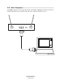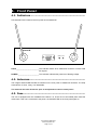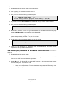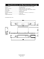
1
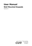
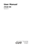
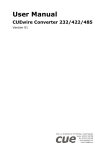
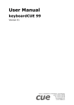
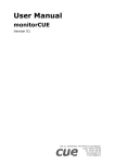
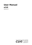
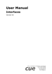
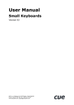
User Manual
rfbaseCUE
Version 03
CUE, a.s., Na Dolinách 6, 147 00 Praha 4, Czech Republic
phone: +420 241 433 555
fax: +420 241 432 446
www.cuesystem.com
e-mail: [email protected]
User Manual rfbaseCUE
UM011_03, 01.04.2003
Copyright © CUE, a.s. Praha, Czech Republic 1990 - 2003.
All rights reserved. Specifications are subject to change without prior notice.
Table of Contents
1.
Introduction .................................................................................................................................... 4
1.1. Overview................................................................................................................................................. 4
1.2. Models .................................................................................................................................................... 4
1.3. Features ................................................................................................................................................. 4
2.
Mounting......................................................................................................................................... 5
3.
Connecting ..................................................................................................................................... 6
3.1. CUEwire ................................................................................................................................................. 6
3.2. Host Computer ....................................................................................................................................... 7
4.
Front Panel ..................................................................................................................................... 8
4.1. Indicators ................................................................................................................................................ 8
4.2. Antennas ................................................................................................................................................ 8
4.3. Fuse........................................................................................................................................................ 8
5.
Service Mode.................................................................................................................................. 9
5.1.
5.2.
5.3.
5.4.
5.5.
6.
Overview................................................................................................................................................. 9
How to Check Firmware Version ............................................................................................................ 9
Starting Service Mode ............................................................................................................................ 9
Upgrading the Firmware ........................................................................................................................10
Modifying Address of Wireless Control Panel........................................................................................11
Troubleshooting........................................................................................................................... 12
6.1. The Power Indicator does not Lights .....................................................................................................12
6.2. The Short Operating Range...................................................................................................................12
7.
Specifications and Mechanical Drawings ................................................................................. 13
8.
Software and Firmware License................................................................................................. 14
9.
Warranty Conditions ................................................................................................................... 15
10. CE Declaration of Conformity..................................................................................................... 16
11. FCC................................................................................................................................................ 17
User Manual rfbaseCUE
www.cuesystem.com
Page 3 of 18
1. Introduction
1.1. Overview....................................................................
rfbaseCUE is a smart device that links RF wireless control panels to CUEwire (RS-485). The
transceiver uses two fixed antennas and is supplied with rack mount brackets for installation in a 19”
rack.
Main functions are
• Receives data from wireless RF control panels and transfers them via CUEwire (RS-485) to
the control units (Assistant or Assistant-S).
• Receives data from CUEwire (RS-485) and transfers them via RF to wireless RF control
panels.
• Stores data when the wireless RF control panels are not active or out of range and transfers
them when the connection is newly established.
1.2. Models .......................................................................
Model
Product code
Description
rfbaseCUE
CS0171-4
RF base unit, 433.92 MHz
rfbaseCUE
CS0171-8
RF base unit, 869.85 MHz
rfbaseCUE
CS0171-9
RF base unit, 914.5 MHz
1.3. Features.....................................................................
The main features of the base unit are
•
•
•
•
•
•
PC host connector for service and programming
CUEwire (RS-485) connection for communication with central unit of control system
Two ¼ wave whip antennas
Power supply 24 VDC (+/-20%), 2 W
RF frequency 433.92 MHz or 869.85 MHz or 914.5 MHz
RF power max. 10 mW (for 433.92 MHz) or max. 1 mW (for 869.85 MHz and 914.5 MHz)
User Manual rfbaseCUE
www.cuesystem.com
Page 4 of 18
2. Mounting
To fix the rfbaseCUE in a 19” rack use rack mount interface kit 19” fastened on to both sides of the
rfbaseCUE using screws.
User Manual rfbaseCUE
www.cuesystem.com
Page 5 of 18
3. Connecting
3.1. CUEwire .....................................................................
The rfbaseCUE needs to be connected to CUEwire (RS-485 and power supply 24 VDC) in the same
way as other control panels.
Important note
There can be only one rfbaseCUE in one control system.
The rear panel is equipped with 4-pin type connector for CUEwire (RS-485 and power supply)
connection. The unit is supplied by 24 VDC (+/-20%), 2 W.
rfbaseCUE
RS 485
+
-
A
B
1
2
3
4
BA+
Ground
+ 24 VDC
The following table describes all CUEwire signals.
Code
IN
RS-485
Pin nr.
1
2
3
4
Meaning
+24 V
Ground
Input/output A+
Input/output B-
Description
Power input 24 VDC
Note
RS-485
RS-485 connection
User Manual rfbaseCUE
www.cuesystem.com
Page 6 of 18
3.2. Host Computer ...........................................................
The HOST connector on the front side serves for firmware upgrading and service functions. A
standard cable Sub-D, 9-pin, female to male, pin to pin is used for connection to a PC.
rfbaseCUE
POWER
AI
HOST
DATA
AO
User Manual rfbaseCUE
www.cuesystem.com
Page 7 of 18
4. Front Panel
4.1. Indicators ..................................................................
LED indicators are located on the front panel of the rfbaseCUE.
rfbaseCUE
POWER DATA
AI
HOST
AO
DATA _________________________ This indicator blinks when rfbaseCUE receives or sends valid
RF signals.
POWER _______________________ This indicator indicates the presence of feeding voltage.
4.2. Antennas....................................................................
The integral antennas AO and AI are situated on the front panel of rfbaseCUE interface. The whip
antennas are ¼ wave, rotary, non-detachable.
The antennas are to be directed to open air and placed not close to metal pieces.
4.3. Fuse ...........................................................................
The unit is equipped with one resettable fuse rated 0.3 A. There are no serviceable parts inside the
metal case. If the unit is connected to the power, the POWER LED on the front panel lights on.
User Manual rfbaseCUE
www.cuesystem.com
Page 8 of 18
5. Service Mode
5.1. Overview....................................................................
The rfbaseCUE interface is provided with special service mode for servicing, testing and upgrading
firmware functions. To operate it, connect the rfbaseCUE to a PC and run proper communication
program - Windows Terminal or other similar general terminal program.
5.2. How to Check Firmware Version ................................
Before starting, please check first if you have all the following items
1. Windows PC with one free serial port.
2. Windows 95/98/NT/2000 with installed Terminal program or HyperTerminal in Windows
95/98/NT/2000.
3. Communication cable between rfbaseCUE HOST connector and PC.
Connect your PC to the rfbaseCUE HOST connector. Start the terminal program on your PC and then
set communication parameters to
Baud Rate....................................................19200
Data Bits ......................................................8
Stop Bits ......................................................1
Parity............................................................None
Flow Control ................................................Xon/Xoff
Connector ....................................................COM1 or COM2 (depending on which channel is used).
Switch off and on the power for the rfbaseCUE.
On your PC monitor you will see the type of version and the revision code. The message format is as
follows.
RfbaseCUE V0.01
7.3.00
5.3. Starting Service Mode ................................................
Before starting, please check first if you have all the following items
1. Windows PC with one free serial port.
2. Windows 95/98/NT/2000 with installed Terminal program or HyperTerminal in Windows
95/98/NT/2000.
3. Communication cable between rfbaseCUE HOST connector and PC.
Disconnect RS-485 signals A and B on the rear panel of rfbaseCUE.
User Manual rfbaseCUE
www.cuesystem.com
Page 9 of 18
There are two ways how to start the rfbaseCUE to operate in service mode.
1. Standard entry of service mode
Connect your PC to the rfbaseCUE HOST connector and run program SRVRFB.EXE. It switches
the rfbaseCUE into service mode.
2. Low level entry of service mode
If the rfbaseCUE does not respond to you or you do not have program SRVRFB.EXE, you must
remove upper cover of the rfbaseCUE. This way you get the access to buttons RESET an TEST
on the printed board. The TEST button is situated near receiving RF module while RESET button
is situated near microprocessor.
Then do the following
• Press both buttons on rfbaseCUE interface: RESET and TEST.
• Release RESET button still holding TEST for several more sec. (approx. 5 sec. is enough).
This will cause the rfbaseCUE to start in service mode.
When the unit is in service mode, the DATA LED indicator starts to blink regularly.
Start the terminal program on your PC and then set communication parameters to
Baud Rate....................................................19200
Data Bits ......................................................8
Stop Bits ......................................................1
Parity............................................................None
Flow Control ................................................Xon/Xoff
Connector ....................................................COM1 or COM2 (depending on which channel is used).
By pressing N button in terminal program the following message appears.
CRAM not installed
rfbaseCUE V0.8 SERVICE mode: H,L,G,J,X,C,R,N,F,Z,P,S,M
>
Now the rfbaseCUE is waiting for commands from PC keyboard. Selecting H you will see a brief
description of each service mode commands on your monitor.
5.4. Upgrading the Firmware ............................................
Before starting, please check first if you have all the following items
1. File RFBxxx.ASX for the rfbaseCUE containing desired firmware version on your hard disc or
floppy disc. The latest firmware version is published regularly on the Cue’s web site
www.cue.cz.
2. Windows PC with one free serial port.
3. Windows 95/98/NT/2000 with installed Terminal program or HyperTerminal in Windows
95/98/NT/2000.
4. Communication cable between rfbaseCUE HOST connector and PC.
User Manual rfbaseCUE
www.cuesystem.com
Page 10 of 18
Steps are
1. Enter the rfbaseCUE service mode as described above.
2. For upgrading the rfbaseCUE firmware select D.
3. On your PC monitor the following message appears.
>d
* * * DOWNLOAD FLASH MEMORY * * *
Do you really wish to reprogram flash memory ? (Yes/No)
4. If you have a new file RFBxxx.ASX for the rfbaseCUE and you want to continue select Y.
5. On your PC monitor the following message appears.
YES - Download start!
Send - file... mode: 19200,8,N,1,XON-XOFF
6. Now select "Transfers" in menu of HyperTerminal and then "Send Text File". Choose proper
setting for RFBxxx.ASX file and transfer it to the rfbaseCUE.
7. The PC will start to send upgrading data to the rfbaseCUE. Each successful transfer of data
packet is responded by character "." on your PC monitor.
8. At the end the following message appears on your PC monitor.
........................
Download flash memory end!
>
9. Finally you can disconnect PC. Switch the power for the rfbaseCUE off and on to start
operation of new upgraded firmware version.
5.5. Modifying Address of Wireless Control Panel .............
Steps are
1. Enter the rfbaseCUE service mode.
2. Put the wireless control panel into RF communication range and set condition for MODIFY
function (for rfCUE press and hold back-light button).
3. Select M on PC. The rfbaseCUE will send via RF message to wireless control panel to enter
it’s own Modify mode. It means for rfCUE
• When the back-light button is pressed – its current address is displayed.
• When the back-light button and some other button are pressed simultaneously – it will
modify and display the address. For further details see rfCUE user manual.
User Manual rfbaseCUE
www.cuesystem.com
Page 11 of 18
6. Troubleshooting
6.1. The Power Indicator does not Lights..........................
Check the power supply regarding to the right output voltage. If the POWER indicator still does not
light contact the dealer.
6.2. The Short Operating Range ........................................
1. Check batteries in the wireless RF control panels.
2. Check the presence of disturbing RF signals (frequencies of other RF operating equipment in
the installation).
3. Change position of the rfbaseCUE or its antennas.
User Manual rfbaseCUE
www.cuesystem.com
Page 12 of 18
7. Specifications and Mechanical Drawings
Communication............................................Two-way, radio frequency 433 / 869 / 914 MHz
Antenna .......................................................(2) whip antennas
System connection ......................................CUEwire (RS-485), 4-pin connector
Service port .................................................RS-232 for host computer, DB-9-female connector
Power supply ...............................................24 VDC (+/- 20%), 2 W
Enclosure.....................................................Stainless steel
Dimensions (WxHxD) ..................................175 mm (6.9”) x 44 mm (1.7”) x 105 mm (4.1”)
Weight..........................................................0.9 kg / 2 lb
Supplied accessories...................................Rack mount kit 19”
All dimensions are in mm.
User Manual rfbaseCUE
www.cuesystem.com
Page 13 of 18
8.
Software and Firmware License
END-USER NOTICE AND LICENSE AGREEMENT FROM CUE, spol. s r.o.
NOTICE TO END-USER
CAREFULLY READ THE FOLLOWING LEGAL AGREEMENT (THIS "LICENSE"). INSTALLATION OR USE OF THE
ENCLOSED CUE, spol. s r.o. SOFTWARE PROGRAMS (COLLECTIVELY, "SOFTWARE") ON YOUR COMPUTER
SYSTEMS OR HARDWARE DEVICES CONSTITUTES YOUR ACCEPTANCE OF THESE TERMS. IF YOU DO NOT AGREE
TO THE TERMS OF THIS LICENSE, PROMPTLY DELETE THE SOFTWARE FROM YOUR COMPUTER SYSTEMS AND
HARDWARE DEVICES, DESTROY ANY COPIES YOU MADE OF THE SOFTWARE OR ANY INSTALLATION MEDIA OF THE
SOFTWARE INCLUDED WITH YOUR SYSTEM, AND DISPOSE OF ALL WRITTEN MATERIALS IN YOUR POSSESSION
REGARDING THE SOFTWARE.
License Grant
CUE grants to You, as an individual, a license to install and use one (1) copy of the Software on a single computer at a time;
provided, however, that You may make copies of the Software solely for Your development of applications for CUE hardware
and demonstration versions of such applications. Any applications created with the Software may only be used with Cue
hardware. Your license to use the Software is conditioned upon Your compliance with the terms of this License. A License is
required for each end-user of the Software. A license is required for each installation of the Software. You may make one (1)
copy of the Software for archival purposes only. You may use this Software only in connection with CUE hardware. You must
have acquired the Software directly in connection with the purchase of CUE hardware from CUE or from a CUE approved
reseller for this license to be effective. If You have purchased a Site License, You may complete only the number of
installations specified in the License Agreement accompanying the Software.
Copyright
The Software and software built into CUE hardware ("Firmware") are protected by copyright law and international treaty
provisions. You acknowledge that no title to the intellectual property in the Software and Firmware is transferred to You. You
further acknowledge that title and full ownership rights to the Software and Firmware will remain the exclusive property of CUE,
and You will not acquire any rights to the Software and Firmware except as expressly set forth in this License. You agree that
any copies of the Software will contain the same proprietary notices which appear on and in the Software.
Prohibited Uses
Without obtaining prior written permission from CUE, You may not (a.) use, copy, modify, alter, or transfer the Software or
documentation except as expressly provided in this License; (b.) translate, disassemble, decompile, reverse program or
otherwise reverse engineer the Software and Firmware; (c.) sublicense or lease the Software or its documentation (d.) use this
Software with any hardware other than products produced by CUE or in connection with applications being developed for CUE
hardware; or (e.) use the Software in a multi-user, network, or multiple computer environment or in a rental, time sharing or
computer service business. Without prejudice to any other rights, CUE may terminate this License if You fail to comply with its
terms and conditions. In such event, You must immediately destroy all copies of the Software.
No Other Warranties
CUE DOES NOT WARRANT THAT THE SOFTWARE AND FIRMWARE IS ERROR FREE. CUE DISCLAIMS ALL
WARRANTIES WITH RESPECT TO THE SOFTWARE AND FIRMWARE, EITHER EXPRESS OR IMPLIED, INCLUDING BUT
NOT LIMITED TO IMPLIED WARRANTIES OF MERCHANTABILITY, FITNESS FOR A PARTICULAR PURPOSE AND
NONINFRINGEMENT OF THIRD PARTY RIGHTS. SOME JURISDICTIONS DO NOT ALLOW THE EXCLUSION OF IMPLIED
WARRANTIES OR LIMITATIONS OF HOW LONG AN IMPLIED WARRANTY MAY LAST, OR THE EXCLUSION OF
LIMITATION OF INCIDENTAL DAMAGES, SO THE ABOVE LIMITATIONS OR EXCLUSIONS MAY NOT APPLY TO YOU.
THIS WARRANTY GIVES YOU SPECIFIC LEGAL RIGHTS AND YOU MAY ALSO HAVE OTHER RIGHTS WHICH VARY
FROM JURISDICTION TO JURISDICTION.
No Liability for Consequential Damages
IN NO EVENT SHALL CUE BE LIABLE TO YOU FOR ANY CONSEQUENTIAL, SPECIAL, INCIDENTAL, OR INDIRECT
DAMAGES OF ANY KIND ARISING OUT OF THE PERFORMANCE OR USE OF THE SOFTWARE, EVEN IF CUE HAS BEEN
ADVISED OF THE POSSIBILITY OF SUCH DAMAGES.
Label on Hardware
Use of this hardware and the software programs controlling this hardware is subject to the terms of the Software and Hardware
License Agreements (the “License Agreements”). You should not use the software and hardware until you have read the
License Agreements. By using the software and hardware, you signify that you have read the Licenses Agreements and accept
their terms. The “License Agreement” is available at www.cuesystem.com.
Trademark Notice
CUE and the CUE logo are trademarks of CUE spol. s r.o. in the United States and in other countries.
User Manual rfbaseCUE
www.cuesystem.com
Page 14 of 18
9.
Warranty Conditions
Warranty Duration
CUE provides warranty for all CUE products for a period of 3 years from the day of purchase. The provided warranty for touch
screens is 2 years from the day of purchase. CUE accepts reclamation of 5 not properly working dots and more (2 dots join – 1
counts). The warranty provided for rechargeable accumulators is 6 months from the day of purchase
Liability
CUE is not liable for any consequential damage caused by CUE products including any loss of profits, incidental or
consequential damages or any claims made by a third parties.
General Warranty Terms
a)
b)
c)
d)
CUE warrants that its products are without defects in material and are fully functional for the duration of the warranty.
Warranty repairs are free of charge. The customer will send the damaged device to CUE at his cost.
All warranty repairs and after warranty services are made at CUE premises. It is strictly prohibited to repair CUE
products or to change any accessory parts, except those parts with limited service life. CUE is not liable for
consumables or parts with limited service life (lamps, batteries etc.)
The warranty further does not apply to the following cases
•
Damages caused by operating the system not according to the conditions defined in user manual or
instruction (wrong power supply voltage, operation outside deferred temperature range, operation in humid
environment and mechanical damages).
•
Damages caused by faulty service, maintenance, connection, and use of other than original connection
cable.
•
Damage caused by agencies i.e. incidental or unpredictable impacts (fire, earthquake, flood, thunder,
strong electric induction, water, strong wind, theft, vandalism etc.)
After Warranty Services
a)
b)
c)
All warranty repairs are normally on a ‘back to base’ basis, as defined in 3 c)
All out warranty repair costs will be fully charged to the customer.
In cases where our staff are called out to assist, cost of transport and time will be at customer cost
User Manual rfbaseCUE
www.cuesystem.com
Page 15 of 18
10. CE Declaration of Conformity
We, the producer
CUE spol. s r. o., Na Dolinách 6, Praha 4, Czech Republic
acknowledge our sole responsibility, that the product incl. accessories
Kind of equipment
Remote Control System
Type designation
CS0197 touchCUE-L 99, CS0159 touchCUE 99, CS0157 touchCUE-S 99,
CS0183 touchCUE-V, CS0198 touchCUE-L, CS0200 touchCUE-M, CS0176 touchCUE-MM, CS0122 touchCUE,
CS0142 touchCUE-S,
CS0178 touchCUE-V /t, CS0199 touchCUE-L /t, CS0204 touchCUE-M /t, CS0143 touchCUE-S /t,
CS0158 touchCUE-S /w,
CS0224 touchCUE-S /d,
CS0205 touchCUE-M /r, CS0144 touchCUE-S /r
ST0007 Guide, CS0188 touchCUE-SRF, CS0171 rfbaseCUE,
ST0013 monitorCUE-V, CS0203 monitorCUE, CS0190 touchCUE-V /i, CS0151 PC Interface 485
CS0170 rfCUE 99, CS0170 rfCUE 99, CS0149 irCUE 99, CS0133 irCUE, CS0080 irCUE Receiver,
CS0169 irCUE Receiver 485,
CS0221 keypadCUE-1G, CS0222 keypadCUE-2G, CS0223 keypadCUE-3G,
CS0145 keyboardCUE 99, CS0128 keyboardCUE, CS0174 keyboardCUE-S, CS0129 keyboardCUE /t,
CS0146 keyboardCUE-S /w, CS0130 keyboardCUE /r, CS0191 inputCUE,
CS0173 eCUE
CS0051 Assistant, CS0150 Assistant-S, CS0100 PC Card, CS0227 CUEwire Splitter,
CS0008 smartCUE, CS0201 sbiCUE-DMX, CS0009 soundCUE, CS0004 analogCUE, CS0005 auxCUE,
CS0165 PED202, CS0166 PEF200, CS0167 PER610, CS0163 PEC25, CS0225 PEA208, CS0164 PED108,
CS0184 CUEadapter /10W, CS0226 CUEadapter /20W, CS0185 CUEadapter /50W, CS0186 CUEadapter /80W,
CS0168 PES03, CS0016 powerAUX,
PT0005 Cue Director, PT0004 Teach-In, PT0006 WinKit
in accordance with EMC Directive 89/336/EEC,
is in compliance with the following norms or documents:
EN50082-1 (IEC801-2), IEC65(CO)39, DIN VDE 0839 part 82-1, DIN VDE 0843 part 4, IEC801-4,
EN50081-1 EN55022 class B, DIN VDE 0839 part 81-1, EN55014, EN55011.
Jaroslav Dibitanzl
Member of Board of Directors
User Manual rfbaseCUE
www.cuesystem.com
Page 16 of 18
11. FCC
Caution
Changes or modifications to this unit not expressly approved by the party responsible for compliance could void the user's
authority to operate the equipment.
Note
This equipment has been tested and found to comply with the limits for a Class B digital device, pursuant to Part 15 of the FCC
Rules. These limits are designed to provide reasonable protection against harmful interference in a residential installation. This
equipment generates, uses and can radiate radio frequency energy and, if not installed and used in accordance with the
instructions, may cause harmful interference to radio communications. However, there is no guarantee that interference will not
occur in a particular installation. If this equipment does cause harmful interference to radio or television reception, which can be
determined by turning the equipment off and on, the user is encouraged to try to correct the interference by one or more of the
following measures:
•
Reorient or relocate the receiving antenna.
•
Increase the separation between the equipment and receiver.
•
Connect the equipment into an outlet on a circuit different from that to which the receiver is connected.
•
Consult the dealer or an experienced radio / TV technician for help.
User Manual rfbaseCUE
www.cuesystem.com
Page 17 of 18
Notes
User Manual rfbaseCUE
www.cuesystem.com
Page 18 of 18