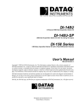
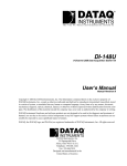
1
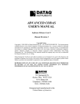
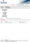
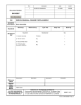
Beacon 410 DI-148U Data Acquisition
Supplement to the Beacon 410
Operator’s Manual
Part Number: 71-0193RK
Revision: P1
Released: 6/4/10
www.rkiinstruments.com
Product Warranty
RKI Instruments, Inc. warrants gas alarm equipment sold by us to be free from defects in
materials, workmanship, and performance for a period of one year* from the date of
shipment from RKI Instruments, Inc. Any parts found defective within that period will be
repaired or replaced, at our option, free of charge. Parts must be returned to RKI
Instruments, Inc. for repair or replacement. This warranty does not apply to those items
which by their nature are subject to deterioration or consumption in normal service, and
which must be cleaned, repaired or replaced on a routine basis. Examples of such items
are:
a) Pump diaphragms and valves
c) Batteries
b) Fuses
d) Filter elements
Warranty is voided by abuse including mechanical damage, alteration, rough handling, or
repair procedures not in accordance with instruction manual. This warranty indicates the
full extent of our liability, and we are not responsible for removal or replacement costs,
local repair costs, transportation costs, or contingent expenses incurred without our prior
approval.
THIS WARRANTY IS EXPRESSLY IN LIEU OF ANY AND ALL OTHER
WARRANTIES AND REPRESENTATIONS, EXPRESSED OR IMPLIED, AND
ALL OTHER OBLIGATIONS OR LIABILITIES ON THE PART OF RKI
INSTRUMENTS, INC. INCLUDING BUT NOT LIMITED TO, THE WARRANTY OF
MERCHANTABILITY OR FITNESS FOR A PARTICULAR PURPOSE. IN NO
EVENT SHALL RKI INSTRUMENTS, INC. BE LIABLE FOR INDIRECT,
INCIDENTAL OR CONSEQUENTIAL LOSS OR DAMAGE OF ANY KIND
CONNECTED WITH THE USE OF ITS PRODUCTS OR FAILURE OF ITS
PRODUCTS TO FUNCTION OR OPERATE PROPERLY.
This warranty covers instruments and parts sold to users only by authorized distributors,
dealers and representatives as appointed by RKI Instruments, Inc.
We do not assume indemnification for any accident or damage caused by the operation of
this gas monitor and our warranty is limited to the replacement of parts or our complete
goods. Warranty covers parts and labor performed at RKI Instruments, Inc. only, and does
not cover field labor or shipment of parts back to RKI.
2 • Model GD-K8A4X Sample Draw Transmitter
Overview
This supplement describes the Beacon 410 Data Acquisition Device. It also describes how
to install and startup the Beacon 410 Data Acquisition Device computer program.
Description
Beacon 410
The Beacon 410 is a wall-mounted unit that can detect up to 4 gases. A digital display that
is visible through the housing door displays the current gas readings. Conduit hubs in the
bottom of the housing allow for connection or wiring of detector heads. See the Beacon
410 Operator’s Manual for further description.
DATAQ DI-148U Data Acquisition Device
The DI-148U Data Acquisition Device is installed inside the housing door of the Beacon
410. See reference drawing 82-5103RK-10-R01 for the specific location.
The DI-148U takes voltage data and converts it to a digital signal. This requires the 4-20
mA outputs of the Beacon 410 to be converted to a voltage output. This is done by
measuring the voltage drop across a 249 Ohm resistor. This changes the 4-20 mA output
for each channel to a nominal 1-5 V output. This information is transmitted from the Data
Acquisition Device to the computer via a USB cable that is provided with the unit.
Installation
This section describes the factory setup and wiring of the Beacon 410. It also describes
how to install the Beacon 410 Data Acquisition Device software and set up the program.
Beacon 410
See the Beacon 410 operator’s manual for instructions to install the Beacon 410.
Factory Settings/Wiring
The Beacon 410 has been factory wired to the Data Acquisition Device. A 249 Ohm resistor
has been placed across the 4-20mA output of each channel. This allows the Data
Acquisition Device to measure the voltage drop and convert it to a digital signal.
Jumpers connecting the negative ports of the 4-20mA output terminal strips are also
factory installed to ensure a common DC ground (see reference drawing 82-5103RK-R03).
Each channel’s 4-20 mA output + terminal is connected to the respective port number on
the Data Acquisition Device (see reference drawing 82-5103RK-R03).
Installing the DI-148U Program
Before installing the program, make sure the Beacon 410 is plugged in. To install the DI148U computer program, do the following:
1.
Insert the WinDaq resource product CD into your computer and follow the
instructions for installation.
Be sure to install the program for the correct device: DI-148U.
2.
Connect the Data Acquisition Device to your computer via the USB cable.
3.
Click “Finish”.
Model GD-K8A4X Sample Draw Transmitter • 3
NOTE: The installation process puts a shortcut on the desktop called DATAQ
Instruments Hardware Manager. For convenience use this shortcut to start the
Hardware Manager.
Configuring the Program
Factory Configuration
The factory configuration for the Data Acquisition Device can be imported using a factory
generated data file provided by RKI Instruments, Inc. To import this file:
1.
Open the DATAQ Instruments Hardware Manager.
2.
A window opens and indicates that it is searching for devices.
3.
Once the program is done searching, select the device installed in the Beacon 410 and
double click “Start Windaq”. The main program window appears.
4.
Click “File” in the menu bar and select “Open Reference File”.
5.
Select the factory generated data file you wish to import. A factory generated data file
was provided by RKI Instruments, Inc. on a CD with the system. The file name is
rkib410configxx.wdq where xx is the configuration number.
6.
Click “Open”. The file will be opened and the main program screen will reflect the
settings.
7.
To save the current setup as a default, you must click “File” in the menu bar and select
“Save Default Setup”.
NOTE: If you do not save the default setup and the Windaq program is closed, you will
need to import the reference file again to obtain the desired setup.
User Configuration
The user may modify the factory configuration or configure additional channels. Do the
following:
1.
Open the DATAQ Instruments Hardware Manager.
2.
A window opens and indicates that it is searching for devices.
3.
Once the program is done searching, select the device installed in the Beacon 410 and
double click “Start Windaq”. The main program window appears.
4.
To add or delete a channel from the program screen, click “Edit” in the menu bar and
select “Channels”. Check marks will appear for channels currently being displayed
on the main screen. Channels not currently being displayed will have empty boxes.
Click in the box for the channel you wish to add or delete, respectively.
5.
To select how many channels to display on the screen, click “View” in the menu bar,
select “Format Screen”, and make your selection.
6.
To properly configure a channel, the following needs to be setup: scaling limits, low
and high DI-148U input calibration values, and the channel user annotation.
7.
When editing current settings or initially defining a channel, the limits must be set up
first. Select the channel you wish to define by clicking it.
8.
Click “Scaling” in the menu bar and select “Limits” from the dropdown menu.
9.
The top and bottom limits must be defined. Since every channel has a nominal output
4 • Model GD-K8A4X Sample Draw Transmitter
of 1-5 V, the top and bottom limits for all channels are the same. The top limit is 4.98
and the bottom limit is 0.996.
10. Use the “Next” or “Previous” button to save the settings and move to any other
channels you wish to setup. When you are done, click “OK” to save the last setting
and exit the Limits window.
11. Select the channel you would like to set up for low and high calibration values.
12. Click “Edit” in the menu bar and select “Low Calibration” from the dropdown menu.
The Low Calibration Window allows the user to input the zero calibration values for
each channel.
•
Set the input level for “Low Cal” to 0.996.
•
All channels will have a “Cal Value” of 0.
•
The “Engr. Units” box allows the user to define the units displayed with the
reading.
13. Click “Edit” in the menu bar and select “High Calibration” from the dropdown menu.
The High Calibration Window allows the user to input the response calibration values
for each channel.
•
Set the input level for “High Cal” to 4.98.
•
The “High Cal Value” is the full scale of the monitored channel. For oxygen
channels, it is 25. For combustible gas channels, it is 100.
•
The “Engr. Units” box allows the user to define the units displayed with the
reading.
14. Click “Edit” in the menu bar and select “User Annotation” from the dropdown menu.
This window allows the user to enter a channel name for the selected channel. This
channel name is only visible on the main screen if “User Annotation” is selected
under the “Options” tab in the main menu.
15. To save the current setup as a default, you must first click “File” in the menu bar and
select “Record”. Name the file, choose the directory to save it in, and press “Open”.
Click “File” in the menu bar and select “Save Default Setup”.
For more information regarding installation and start-up of the Windaq Serial Acquisition
Software, see the User’s Manual for the DI-148U provided by DATAQ Instruments on the
product CD. Also see the Help Menu located under the “Help” tab of the menu bar.
NOTE: If technical support is required for the DI-148U or the Windaq Serial Acquisition
Software, contact DATAQ. See the Installation Guide provided with the data
acquisition kit for contact information.
Start Up
1.
Complete the installation procedures described earlier in this supplement.
2.
Start up the Beacon 410. See the Beacon 410 operator’s manual for startup
instructions.
3.
Open the DATAQ Instruments Hardware Manager.
4.
A window opens and indicates that it is searching for devices.
5.
Once the program is done searching, select the device installed in the Beacon 410 and
Model GD-K8A4X Sample Draw Transmitter • 5
double click “Start Windaq”. The main program window appears.
Saving Data to Disk
Data can be recorded and saved in a file to be viewed at a later date.
1.
Define the sample rate by clicking “Edit” in the menu bar and selecting “Sample
Rate”.
2.
Enter the desired value in the sample rate box and press “OK”.
3.
Click “File” in the menu bar and select “Record”.
4.
Enter a file name, choose the directory path you would like to save the file in, and
click “Open”.
5.
In the window that comes up, enter the maximum file size for the data file. The
available recording time based on the sample rate you entered earlier will be
displayed.
6.
To start recording and saving data to a file, click “OK”.
NOTE: For a more complete description of saving the data, see the program Help Files or
the product documentation in the product CD.
Parts List
Table 1 lists replacement parts and accessories for the Beacon 410 with Data Acquisition
Device. See the Beacon 410 Operator’s manual for other spare parts.
Table 1: Parts List
Part Number
Description
71-0193RK
Beacon 410 with Data Acquisition Device Operator’s Manual (this document)
82-5103RK
Data acquisition starter kit with USB interface, 8 channel
Reference Drawing List
Table 2 lists the attached reference drawings for the Beacon 410 with the Data Acquisition
Device.
Table 2: Reference Drawing List
Reference Drawing
Number
Description
82-5103RK-10-R01
Component location, Beacon 410 with DI-148U data acquisition device
82-5103RK-10-R02
General Wiring Diagram, Beacon 410 with DI-148U data acquisition device
82-5103RK-10-R03
Factory Wiring Diagram, Beacon 410 with DI-148U data acquisition device
6 • Model GD-K8A4X Sample Draw Transmitter