1
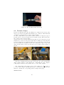
Lithium System Operation
Dan Lev and David Stein
March 1, 2011
(or Lithium tank for dummies)
1
Contents
1 Introduction
4
2 Main Goal and challenges
5
3 System Architecture
6
4 Feed System
4.1 General Introduction . . . . . . . .
4.1.1 Part Numbers for Ordering
4.2 Reservoir . . . . . . . . . . . . . .
4.3 Cylinder . . . . . . . . . . . . . . .
4.4 Piston . . . . . . . . . . . . . . . .
4.5 Piston Motor . . . . . . . . . . . .
4.6 Freeze Valve . . . . . . . . . . . . .
4.7 Reservoir Line and Thruster Line .
4.8 Argon Feed . . . . . . . . . . . . .
4.8.1 Part Numbers for Ordering
4.9 Piston LVDT . . . . . . . . . . . .
.
.
.
.
.
.
.
.
.
.
.
.
.
.
.
.
.
.
.
.
.
.
.
.
.
.
.
.
.
.
.
.
.
.
.
.
.
.
.
.
.
.
.
.
.
.
.
.
.
.
.
.
.
.
.
.
.
.
.
.
.
.
.
.
.
.
.
.
.
.
.
.
.
.
.
.
.
.
.
.
.
.
.
.
.
.
.
.
.
.
.
.
.
.
.
.
.
.
.
.
.
.
.
.
.
.
.
.
.
.
.
.
.
.
.
.
.
.
.
.
.
.
.
.
.
.
.
.
.
.
.
.
.
.
.
.
.
.
.
.
.
.
.
.
.
.
.
.
.
.
.
.
.
.
.
.
.
.
.
.
.
.
.
.
.
9
9
11
12
13
14
16
17
18
19
20
21
5 Thermal Control
5.1 Heaters . . . . . . . . . . . . . . . . . .
5.1.1 Reservoir and Cylinder Heaters .
5.1.2 Line Heaters . . . . . . . . . . .
5.1.3 Part Numbers for Ordering . . .
5.2 Thermocouples . . . . . . . . . . . . . .
5.2.1 Part Numbers for Ordering . . .
5.3 Thermocouple Protection Circuit Board
5.4 Water Cooling System . . . . . . . . . .
5.4.1 Part Numbers for Ordering . . .
5.5 Emergency Water Cooling System . . .
.
.
.
.
.
.
.
.
.
.
.
.
.
.
.
.
.
.
.
.
.
.
.
.
.
.
.
.
.
.
.
.
.
.
.
.
.
.
.
.
.
.
.
.
.
.
.
.
.
.
.
.
.
.
.
.
.
.
.
.
.
.
.
.
.
.
.
.
.
.
.
.
.
.
.
.
.
.
.
.
.
.
.
.
.
.
.
.
.
.
.
.
.
.
.
.
.
.
.
.
.
.
.
.
.
.
.
.
.
.
.
.
.
.
.
.
.
.
.
.
.
.
.
.
.
.
.
.
.
.
.
.
.
.
.
.
.
.
.
.
24
24
26
26
28
29
29
31
33
33
34
6 Thruster Operation
6.1 Current Reading . . . . . . . . . .
6.2 Preparation for Firing . . . . . . .
6.2.1 Part Numbers for Ordering
6.3 Check Lists . . . . . . . . . . . . .
6.3.1 Preliminary Checks . . . . .
.
.
.
.
.
.
.
.
.
.
.
.
.
.
.
.
.
.
.
.
.
.
.
.
.
.
.
.
.
.
.
.
.
.
.
.
.
.
.
.
.
.
.
.
.
.
.
.
.
.
.
.
.
.
.
.
.
.
.
.
.
.
.
.
.
.
.
.
.
.
39
39
40
40
41
41
.
.
.
.
.
.
.
.
.
.
.
.
.
.
.
.
.
.
.
.
.
.
.
.
.
.
.
.
.
.
.
.
.
.
.
.
.
7 Thrust Measurement System
42
8 Vacuum System
8.1 Pumps . . . . . . . . . . . . . . .
8.1.1 Short Background . . . .
8.1.2 Pumping Down Sequence
8.1.3 Venting up Sequence . . .
2
.
.
.
.
.
.
.
.
.
.
.
.
.
.
.
.
.
.
.
.
.
.
.
.
.
.
.
.
.
.
.
.
.
.
.
.
.
.
.
.
.
.
.
.
.
.
.
.
.
.
.
.
.
.
.
.
.
.
.
.
.
.
.
.
.
.
.
.
.
.
.
.
43
43
43
44
46
8.2
8.3
8.1.4 Thermostat for Roughing Pump
Pressure Gauges . . . . . . . . . . . . .
FireVent . . . . . . . . . . . . . . . . . .
8.3.1 Part Numbers for Ordering . . .
9 Lithium Handling
9.1 Glove Box . . . . . . . . . . . . . . . .
9.1.1 Short Background . . . . . . .
9.1.2 Working Procedure . . . . . . .
9.1.3 Using the Ante Chamber . . .
9.1.4 Leaks in the Glove Box . . . .
9.1.5 Tips, ”Musts” and ”No Nos” .
9.1.6 Part Numbers for Ordering . .
9.2 Lithium Cleaning . . . . . . . . . . . .
9.2.1 Main Dangers . . . . . . . . . .
9.2.2 Preparation for Tank Opening
9.2.3 Taking the System Apart . . .
9.2.4 Lithium Removal . . . . . . . .
9.2.5 Cathode Cleaning . . . . . . .
9.2.6 Part Numbers for Ordering . .
9.3 Hydrogen Detectors . . . . . . . . . .
.
.
.
.
.
.
.
.
.
.
.
.
.
.
.
.
.
.
.
.
.
.
.
.
.
.
.
.
.
.
.
.
.
.
.
.
.
.
.
.
.
.
.
.
.
.
.
.
.
.
.
.
.
.
.
.
.
.
.
.
.
.
.
.
.
.
.
.
.
.
.
46
48
50
51
.
.
.
.
.
.
.
.
.
.
.
.
.
.
.
.
.
.
.
.
.
.
.
.
.
.
.
.
.
.
.
.
.
.
.
.
.
.
.
.
.
.
.
.
.
.
.
.
.
.
.
.
.
.
.
.
.
.
.
.
.
.
.
.
.
.
.
.
.
.
.
.
.
.
.
.
.
.
.
.
.
.
.
.
.
.
.
.
.
.
.
.
.
.
.
.
.
.
.
.
.
.
.
.
.
.
.
.
.
.
.
.
.
.
.
.
.
.
.
.
.
.
.
.
.
.
.
.
.
.
.
.
.
.
.
.
.
.
.
.
.
.
.
.
.
.
.
.
.
.
.
.
.
.
.
.
.
.
.
.
.
.
.
.
.
.
.
.
.
.
.
.
.
.
.
.
.
.
.
.
.
.
.
.
.
.
.
.
.
.
.
.
.
.
.
.
.
.
.
.
.
.
.
.
.
.
.
.
.
.
52
52
52
53
54
55
56
57
58
58
59
62
63
64
65
67
10 Argon Truster Operation
69
10.1 Sonic Orifice . . . . . . . . . . . . . . . . . . . . . . . . . . . . . 69
10.1.1 Part Numbers for Ordering . . . . . . . . . . . . . . . . . 70
11 Leaks Leaks Leaks
71
11.0.2 Part Numbers for Ordering . . . . . . . . . . . . . . . . . 71
12 Materials
12.1 Lithium . . .
12.2 TZM . . . . .
12.3 Macor . . . .
12.4 Part Numbers
. .
. .
. .
for
. . . . . .
. . . . . .
. . . . . .
Ordering
.
.
.
.
.
.
.
.
13 Troubleshooting
.
.
.
.
.
.
.
.
.
.
.
.
.
.
.
.
.
.
.
.
.
.
.
.
.
.
.
.
.
.
.
.
.
.
.
.
.
.
.
.
.
.
.
.
.
.
.
.
.
.
.
.
.
.
.
.
.
.
.
.
.
.
.
.
.
.
.
.
.
.
.
.
.
.
.
.
72
72
72
72
73
74
3
1
Introduction
In this manual you will find everything you need in order to run the Lithium
tank system and fire the thruster.
The main goal of this manual is to help whoever works on the system learn how
to run it and fix it if needed.
I wrote this manual so to prevent from you the same thing that happened to
me - there was no documentation of anything. The people who built and improved this system over the years did not document almost anything although
they did a great job. There was no explanation of how to use the system, what
components are in it and what the components do.
All of this is now found in this manual. Here you will find a list of components,
sketches, operation procedures, warnings and instructions of how to deal with
problem in case they pop (and they do!).
It would be unwise to just start reading the whole manual from the beginning
to the end. It has a lot of information in it and by the time you finish reading
it you will forget the beginning. I suggest you read the first few chapters until
you get to chapter ?? (’Components’), then go over the components one by
one while trying to operate them separately. In this way you will build some
experience of working on the system while reading the manual. Remember that
this experiment is all about experience.
If you are reading this manual it probably means that sooner or later you will
add something to the system or improve something in it. Please update this
manual if needed. It has no use if it doesn’t change so to match the most recent
system setup. If you do update the manual please do it with Latex and make
sure the date of last update is written on the cover.
Thanks
and may the gods of Lithium be with you
4
2
Main Goal and challenges
The main goal for this experiment is simple, fire an MPD thruster that runs on
lithium and take thrust measurements.
The LiLFA (Lithium Lorentz Force Accelerator) is a MagnetoPlasmaDynamic
(MPD) thruster that uses lithium as propellant. Since lithium is solid in room
temperature there is a need to melt it down and evaporate it while injecting it
into the thruster. This requires the LiLFA to have a large supporting system
that heats up the lithium and injects it into the thruster. Lithium is also a very
corrosive and violent substance when it reacts with almost any other material.
This is why should never be exposed to air or water, this makes lithium very
hard to handle.
The LiLFA is a 30KW thruster thus high currents and heat are involved in its
operation. The power is deposited in the tank on the tank walls and system.
Since there is no convection the system and thruster can cool down only through
conduction and radiation.
If all of the above is not challenging enough the thrust stand is operated on the
principle of inverted pendulum. This makes the thrust stand very sensitive to
heat and as you will see it tends to deflect and drift. Thrust measurements are
not an easy thing in this thruster.
If you are still reading this it means that you haven’t run away from the lab
already, you’re brave :-)
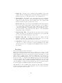
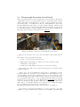
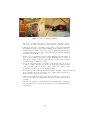
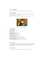
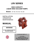
This is a very important chapter since if anything goes wrong and you have
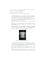
no idea what to do the answer is one: ‘Bob’. Bob, if you don’t know already, is
the lab’s technician. He is familiar with the system and most likely will know
what to do in case you are stuck.
Nevertheless, please turn to Bob as a last resort because it will be more beneficial for you to actually try to confront your problems by yourself. It will also
save some time for Bob. Bob is shown in Fig. 1.
Figure 1: Picture of Bob
Now that you have a general grasp of what you are about to deal with here
you can start reading about the system and try to operate it. Remember, take
your time with this system because every small mistake might cost a great deal
or even be dangerous to you.
5
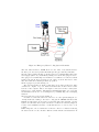
3
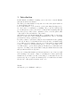
System Architecture
The lithium system can be roughly divided into 4 main separate sections. Each
section takes care of a different aspect of the thrust firing procedure. In order
to fire the thruster you will have to familiarize yourself with all the sections.
The ideal case would be to have at least one graduate student in charge of each
section since the work on each is cumbersome and you won’t have enough time
to work on your PhD thesis otherwise.
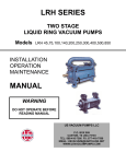
In the next page you will find the schematics for the 4 main sections. The ’Vacuum System’ and the ’Lithium ’Handling’ sections are just supporting systems.
The sections and supporting systems are:
1. Feed System
Goal: Injecting the lithium into the thruster with a set mass flow rate.
Components: The piping line that leads the lithium to the thruster, the
piston that pushes the lithium with a known mass flow rate and the argon
line that pushes the lithium from the reservoir to the cylinder.
2. Thermal Control
Goal: Melting down the lithium so it can be conducted by the feed system. It also makes sure that the temperature of the parts that shouldn’t
get hot stays at the allowed value.
Components: Heaters, thermocouples and cooling water system.
3. Thruster Control
Goal: Taking care of the actual firing of the thruster. It also controls the
magnetic field that is generated by the solenoid.
Components: The thruster, cathode current control and solenoid current control.
4. Thrust Measurement System
Goal: Measuring the thrust.
Components: Position Sensing Device (PSD) and the tilt sensors.
5. Vacuum System
Goal: Keeping the tank under vacuum while any lithium operation is
done in it.
Components: Pumps, pressure gauges and temperature readings for the
Diffusion Pump.
6
6. Lithium Handling
Goal: Treating the lithium in a safe way, load it into the tank and clean
it from the tank after firing.
Components: Glove Box, Hydrogen Detectors and Cleaning Supplies
and procedures.
Almost all the sensors (Thermocouples, LVDT, PSD etc.) are connected to
a Labview program that helps you track the overall operation of the system.
Some controlers (Piston motor control) are controlled directly from Labview.
The rest of the controlers are operated manually by the human operator (you).
This is why you should know how to run Labview and use the Labview files that
are on the computer.
My advice to you is to read the chapters for each one of the sections in the
order that they appear above. Each section relays on the previous sections in
order for it to work properly (if at all). For example, if you want to run a mass
flow rate calibration you will need to know how to operate both the feed system
and the thermal control system.
(The mass flow rate calibration procedure has a chapter of its own in this manual).
7
8
Cold Cathode
Gauge
Roughing
Pump
Convectron
Pressure
Gauge
Roots
Blower
Vacuum
System
Argon Flow
Gauge
(Setra)
Argon
Injection
Piston LVDT
Motor Output
(Position &
Speed)
Piston
Motor
Feed System
Diffusion
Pump
Temperature
Diffusion
Pump
Cooling
Water
Water Flow
Gauges
Thermocouples
Heaters
Thermal Control
System
Solenoid
Current
Control
Hydrogen
Detectors
Cleaning
Supplies
Lithium
Handling
Glove
Box
Labview
Cathode
Current
Control
Thruster
Voltage
Reading
Thruster Operation
System Architecture
PSD
Wire to Labview
Physical
Connection
Diagnostics
Controllable
Device
Tool or Device
Tilt
Sensors
Thrust measurement
System
4
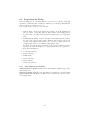
Feed System
4.1
General Introduction
As mentioned before the feed system’s purpose is to inject the lithium into the
feed system with a set mass flow rate. This is done by a set of components
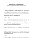
within a piping system. A schematics of the feed system is presented in Fig. 2.
Figure 2: Feed System Schematics
As can be seen in Fig. 2 the feed system is composed out of two main parts
which are the reservoir and the cylinder. The connections between these two
parts along with the connection to the thruster is made out of stainless steel
pipes. The system should be operated and lithium melted only under vacuum of
at least 100 mT . The lack of vacuum will cause the lithium’s surface to interact
with air and it will no longer be useful.
The parts are:
1. Reservoir (Res) - The starting point of the lithium. The lithium is
put there in a solid state at room temperature and melted down using
the heaters that wrap the reservoir. It is made out of stainless steel and
has an inlet (top) and an outlet (bottom). The inlet is used for injecting
argon, as will be explained shortly. The outlet is used for pushing lithium
through it downwards into the thruster line.
2. Cylinder (Cyl) - The place where molten lithium is placed just before
injecting it into the thruster. The heating of the cylinder is crucial for
keeping the lithium at a liquid state.
9
3. Piston (P) - Its purpose is to push the molten lithium out from the
cylinder and into the thruster line towards the thruster. It is pushed by a
massive stepper motor. The piston is made out of stainless steel.
4. Piston Motor - The massive device that pushes the piton downwards.
It is a stepper motor that is controlled directly from the main computer
(’Labview program’) and also sends a signal back to the computer that
indicates the piston’s given position and velocity.
5. Freeze Valve (V) - Prevents the molten lithium from flowing back into
the reservoir after getting pushed down by the piston. It is a chunk of
copper that wraps around the reservoir line. It has a heater in it and a
cooling water path that goes right through it. By controlling the power to
the heater and the cooling water flow it is possible to control the lithium
temperature at the reservoir line.
6. Reservoir Line (RL) - The pipe line in between the reservoir and the
cylinder. It is made out of stainless steel and is formed out of 2 parts that
are connected by NPT and swagelok connections.
7. Thruster Line (TL) - The pipe line between the cylinder and the
thruster. It is made out of stainless steel and is formed out of 5 parts
that are connected by NPT and swagelok connections.
8. Argon Feed - A gas tube that is connected to the argon bottle that’s next
to the glove box. The argon flow is controlled manually from the main
panel and used in order to push the molten lithium from the reservoir to
the cylinder.
Procedure
The general working procedure is as follows:
The reservoir is taken and placed in the glove box under 1 atm of argon. A solid
lithium ingot is then placed in the reservoir which is afterwards sealed. The reservoir
with the lithium is placed in its location in the feed system. The tank is closed and
pumped down to working pressure. All heaters including the reservoir heaters are
turned on and the lithium is melted down. A very low argon flow is injected through
the argon feed tube so to push the molten lithium from the reservoir through the RL
and into the cylinder. Once the cylinder is full with lithium the heaters to the reservoir, valve and RL are turned off while increasing the cooling water to the valve. This
causes the lithium to solidify and seal the RL. The piston is moved with the required
velocity and pushes the lithium through the TL and into the thruster.
Although this procedure of lithium injection might seem quite simple and straight
forward it is long and complicated. Full explanations of how to use all of the subsystems are given in the next few sections.
10
4.1.1
Part Numbers for Ordering
SS 1/4”-1/8” swagelok fitting for lithium Feed Spout: McMaster Carr, Part
Number: 5182k702, Price: $13.20 (NOV 2009)
SS 1/8” Tube for lithium Feed Spout: McMaster Carr, Part Number: 89895k113,
Price: $18.90 (OCT 2009)
SS 1/8” Nut for lithium Feed Spout: McMaster Carr, Part Number: 5182k673,
Price: $2.42 (OCT 2009)
SS 1/8” Front Ferrule for lithium Feed Spout: McMaster Carr, Part Number:
5182k651, Price: $1.53 (OCT 2009)
SS 1/8” Back Ferrule for lithium Feed Spout: McMaster Carr, Part Number:
5182k661, Price: $1.40 (OCT 2009)
2-239 Silicone O-Ring (Reservoir O-Ring): McMaster Carr, Part Number: 9396k228,
Price: $7.11 for a pack of 5 (JAN 2010)
11
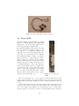
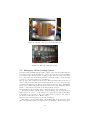
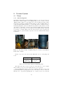
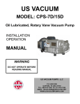
4.2
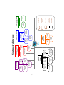
Reservoir
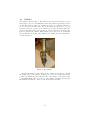
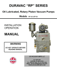
The reservoir is presented in Fig. 3. The reservoir is made out of stainless steel type
316 and consists of two parts, the main reservoir body (container) and the flange. The
flange is sealed by 4 allan bolts. Before closing the flange it is recommended that you
try to align the two marks that are on the reservoir body and flange, as also shown
in Fig. 3. The reservoir has an inlet tube which is also a part of the flange. It is
used for flowing argon and connects to the argon line through an 1/8 inch swagelok
connection. The reservoir also has an outlet tube that connects to the RL through
another 1/8 inch swagelok connection. The two bands that wrap around the reservoir
are heaters and I will elaborate on them in chapter 5. On the top the reservoir is
bolted into the thrust stand plate and is moving with it in the same way the rest of
the feed system is.
Figure 3: The Reservoir and the Reservoir-Flange Alinement
12
4.3
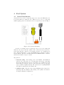
Cylinder
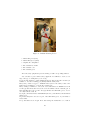
The cylinder is shown in Fig. 4. The cylinder is the next station after the reservoir
and its purpose is to store the lithium in a molten state while it is getting injected into
the TL. The cylinder is made out of stainless steel type 316. It has two inlet tubes,
one is connected to the RL and the other to the TL. Both connections are 1/8 inch
swagelok connections. On the top the cylinder is bolted into the thrust stand plate
and is moving with it in the same way the rest of the feed system is. At that spot the
piston is going into the cylinder. Much similar to the reservoir, the two bands that
wrap around the bottom part of the cylinder are two band heaters. More information
on them in chapter 5.
Figure 4: The Cylinder
The last important part of the cylinder is the cooling water tube that goes around
the middle section of the cylinder. Its purpose is to keep a low temperature at that
point in case lithium slips from the inner side of the cylinder. If it wasn’t for the
cooling lithium might squirt out of the top of the cylinder (as happened in the past).
The swirling water tube is connected to the ’Feed System’ water line.
13
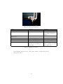
4.4
Piston
The piston is shown in Fig. 5. It is a solid stainless steel cylinder that goes into the
cylinder and pushes the lithium into the TL. The piston is connected to the stepper
motor by a 3/8 − 24 (CHECK THIS NUMBER) screw that goes right into the pin
that’s on the top of the piston. The pin can be taken out easily yet I don’t recommend
doing so unless there is no other choice.
The piston has two rings on it so to create a tight tolerance with the inner wall of
the cylinder and by doing this prevent the lithium from sipping out from the side of
the piston. It already happened in the past that lithium sipped through the side of
the piston and splashed inside the tank. Remember, the piston and the cylinder are
not at a tight tolerance, it is the rings that add a little bit more to that tolerance. A
cross section of the piston is shown in Fig. ??. You can also see how lithium might
sip from the sides so be careful when injecting the argon into the reservoir. You don’t
want to push that lithium too fast into the cylinder.
The two rings are made out of stainless steel type 304 (CHECK THIS !!!) which is
softer since the rings come in contact and might scratch the inner side of the cylinder.
Figure 5: The Piston (left) and a Cross Section of the Piston (right)
The piston has a 1/16 inch hole in it to fit the piston thermocouple. The hole goes
all the way down to about 1 mm from the bottom. This way the thermocouple’s tip
can touch the bottom and sense the lithium as it approaches and touches the piston
without coming in direct contact with the lithium.
The piston’s vertical path inside the cylinder is 150 mm. The piston’s position is
being set from the ’Labview’ program. Anything out of that range will just damage
14
the motor since the piston will push against the top or the bottom of the cylinder.
15
4.5 Piston Motor
In this section there will be a complete explanation on the
piston motor, how it is connected, it’s precision in piston
speed and piston position, the current limit and the control
box
The piston Motor is shown in Fig. 6.
Figure 6: The Piston Motor (Stepper Motor)
16
4.6
Freeze Valve
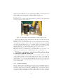
The freeze valve is shown in Fig. 7. It is basically a copper chunk with a heater and
a cooling water tube going through it. The valve mounts around the RL just before
the cylinder. The water or the heater do not come in direct contact with the RL or
the lithium. It is just the copper that touches the RL pipe at a particular point. The
power to the heater is controlled from the valve variac (labeled) and the cooling water
flow is controlled by controlling the water flow in the ’Feed System’ line. The greater
the flow the more heat is taken out from the RL pipe at that point. This is why it
is called a freeze valve because the temperature drops below 180◦ C at that point and
the lithium freezes and clogs the RL. The clogging is necessary when lithium is pushed
by the piston into the TL so that no lithium will get pushed back into the reservoir.
Figure 7: The Freeze Valve
Need a better picture of the valve
In the past there were a few attempts to use an actual stainless steel valve but
the lithium (which is the second smallest molecule) sipped in. Also, the valve was
destroyed over time by the lithium corrosion.
17
4.7
Reservoir Line and Thruster Line
The two lines are shown in Fig. 8.
Figure 8: The RL Line and the TL Line
18
4.8
Argon Feed
The main purpose of the argon feed is to create pressure inside the reservoir so to push
the molten lithium into the RL. Besides this purpose the argon can also keep a steady
flow around the solid ingot so to keep it from interacting with air while the tank is
pumped down.
The argon feed subsystem is composed of the main argon tank, flow gauge, valves out
side of the tank and one valve inside the tank. Schematics of the argon feed subsystem
is shown in Fig. 9.
Figure 9: Argon Feed Subsystem Schematics
The main argon flow is coming directly from the argon bottle that’s next to the
glove box. The line coming out of that bottle goes along the wall and the ceiling until
it reaches the tank from the operator’s side. It then goes into the tank. The argon
flow into the tank is done by using the main argon valve. It consists of a quarter turn
valve and a needle valve. The quarter turn valve should be opened first. It is important to use the needle valve any time you inject argon into the reservoir so you can
control the argon flow with maximal sensitivity. The argon flow after the needle valve
passes through a flow gauge (’Setra’ gauge). The gauge is connected to ’Labview’ and
delivers a signal that is proportional to the gas pressure it senses. It then converts
this pressure into mass flow rate by using the relation in Eq. 1.
Check the Relation with the Setra Gauge Function in Labview
ṁ =
p
2ρA2 (P0 − P )
(1)
Where ρ is the argon density at room temperature, A is the tube’s cross section, P0
is the stagnation pressure and P is the static pressure measured by the ’Setra’ gauge
19
(See Fig. 10).
Since the computer monitor is too far away from the needle valve it is almost impossible to turn the valve and in the same time monitor the argon flow velocity into the
tank. This is why two people should do it carefully while running the experiment. In
the tank the argon flows into the reservoir feed but there is also an option to let the
argon flow into the tank itself. It is done but turn the argon vent valve on (’Open’
position). The argon will still flow into the reservoir feed but now the flow will get
distributed within two lines and therefore will be weaker. The reason for this is so argon pressure won’t build up in the reservoir too quickly and push the lithium very fast
into the cylinder. Remember that the molten lithium is very sensitive to the argon flow.
Figure 10: Argon Flow Meter and Panel
In Fig. 10 you can see both the argon flow meter (’Setra gauge’) and the argon
flow panel. The upper green circle shows the argon flow meter whereas the bottom
green circle the argon vent valve. The latter is basically a two-position switch.
Argon Vent Valve
The argon vent valve is a simple solenoid valve. It is located behind the side left wall.
It requires about 11.3 V to operate. The two positions of the valve are controlled from
the panel by the ’Vent Valve’ toggle switch. The ’close’ position is a de-energized state
and keeps the argon flow from flowing through the vent tube. It will flow directly to
the reservoir feed. The ’open’ position is the energized position and will open the flow
to be both vented into the tank and bled into the reservoir. On a normal daily basis
the valve should be on the de-energized position (’close’). The power to the solenoid
valve is transmitted through the J3 line into the tank.
The most important thing you have to remember about the vent valve is the following:
If you open the valve make sure that argon is flowing. If argon is not flowing into the
argon lines and the vent valve is open then the vacuum will suck the lithium from the
reservoir and into the argon line. This will kill the valve!
The argon vent valve (solenoid valve) is shown in Fig. 11.
4.8.1
Part Numbers for Ordering
Solenoid Valve: 24 V DC, 0.41 Amp, Made by: ’Parker’, Part number: 71215SN2MN00N0C111C2, Distributer: ’McMaster Carr’, Part number: 4639k783
20
Figure 11: Argon Vent Valve (Solenoid Valve)
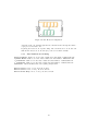
4.9
Piston LVDT
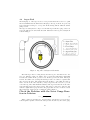
The Piston LVDT is shown in Fig. 12. LVDT
stands for ’Linear Displacement Differential
Transformer’ and as its name implies (in a
weird way) it measures displacement.
In general the LVDT is made in the following
way [?] which is also shown in Fig. 13: it
is composed of a cylindrical channel (also
called the tube) and a ferromagnetic slug (also
called the core) that slides in the channel.
The cylindrical channel consists of a primary
inductor and two secondary inductors. Alternating current is conducted in the primary
inductor. If the slug is not present between the
primary and the secondaries then there won’t
be mutual inductance between the inductors
and no current will flow in the secondaries. The
secondaries are also connected in a 180◦ phase
change so if the slug is equally in between them
the secondary current through each secondary
will cancel the current in the other secondary
and the total current will be zero.
Figure 12: The Piston’s
LVDT
The closer the slug moves to one secondary it couples the inductance from the
primary and the amplitude of the current signal increases. The relation is linear with
displacement hence the name LVDT. For a better explained information check out
source [?].
In the tank the channel (tube) is stationary with the thrust stand and the motor.
The slug (core) is clamped to the piston’s rod through the red box. The slug is screwed
on a 4 − 40 rod that goes through the red box and is clamped by two 4 − 40 nuts. Since
the slug is clamped to the piston’s rod it moves vertically with the piston. Remember
21
Figure 13: A Cross Section of a typical LVDT
that the total vertical path is 150 mm so the LVDT has to be quite long. This fact
makes this LVDT quite expensive. The channel outputs a signal proportional to the
displacement of the piston from a cable at the top of the channel. The way the signal
is transferred to the ’Labview’ chassis is through the ’LVDT1’ cable that is connected
to the LVDT panel (see Fig. 14).
Figure 14: The LVDT Panel
Behind the panel you can find the LPC-2000 box. This is the box that translates
the LVDT signal into a direct voltage signal in the range −5 V < VLV DT < +5 V .
The box needs to be calibrated to the LVDT once in a while. The calibration process
is specified in the LPC-2000 manual. The manual can be found in the end of this manual. Since there is a lot of noise in the system while running the experiment there is
another calibration that needs to be done in ’Labview’. It is done manually by typing
in the offset and slope of the LVDT. This calibration should be done before melting
down the lithium and while the subsystems are on. In order to do this calibration you
need to do the following:
1. Make sure that the LPC-2000 box is calibrated
2. Move piston to 0 mm (It should have been at 0 mm to begin with)
3. Check the LVDT offset in ’Labview’ in the ’Firing’ tag
22
4. Copy this offset number to the ’pos offset (V)’ space at the ’DAQ Setup’ tag
5. Move the piston slowly to 30 mm (I randomly picked this number it can be any
number. The higher the better)
6. Check that physically the piston has moved 30 mm
7. Change the ’pos LVDT cal (V/mm)’ at the ’DAQ Setup’ tag until the piston
position shown at the ’Piston Position LVDT (mm)’ at the ’Firing’ tag is 30 mm
8. Move Piston back to 0 mm and make sure it does indeed go to 0 mm in ’Labview’. If it doesn’t then start the whole procedure again
Now that the LVDT is fully calibrated and you are all set to use it.
Technical Notes
• In case there is a current spike in the system while firing the LPC-2000 box
might get fried and need to be replaced. Have one spair so you won’t have to
wait for shipping.
• As I’m writing these lines there is a problem with the LVDT at piston positions
of above 120 mm. The LVDT needs to be recalibrated by taking the channel
and slug out and checking the system on a workbench.
• The signal from the LVDT is quite flaky and should not be trusted over the
signal from the motor which is much more accurate. The LVDT is there just in
case the motor is damaged or skips a few screw turns and therefore no longer
reliable.
• Before opening the LVDT panel de-energize the LVDT from the power strip.
The LVDT is powered directly from the wall socket with a 120V AC and so
very dangerous!
23
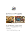
5
Thermal Control
5.1
Heaters
The Heaters have a crucial part in the system, their job is to melt the lithium down so
it can be conducted through the pipe Line. There are many heaters in the system, you
can see them in Fig. 15. In general there are 4 types of heaters, 2 band heaters and
2 coil heaters. The band heaters are wrapped around the reservoir and the cylinder
while the coil heaters are wrapped around the pipe line. The band heater for the
reservoir melts the lithium down. The band heater for the cylinder makes sure that
the lithium doesn’t freeze while it enters the cylinder and while the piston is pushed
downwards. The coil heaters make sure that the lithium doesn’t freeze in the pipe line.
Figure 15: All Types of Heaters
There is an additional heater that heats up the ’Freeze Valve’ but I will talk about
it only in the ’Freeze Valve’ section.
All heaters are getting their power from a simple 120VAC power supply, or as most
people call it: the wall socket. The power is delivered through a set of variacs (Fig. 16).
The role of the variac is to change the AC voltage from any value between 0V and
120V. By turning the knob of the variac you can supply more or less power to the
heaters and heat them up more or less.
Figure 16: Heaters’ Variacs
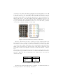
Inside the tank the heaters are connected through a socket panel (Fig. 17). The
24
connection to the panel is as simple as plugging an electrical appliance to the wall
socket. There are 15 sockets out of which only 11 are functional. In Fig. 17 you can
see which connection goes to what heater. The heater lines are labeled according to
the numbers in the figure. Notice that the cylinder has two connections assigned to it.
This gives the option to connect the cylinder’s heaters in parallel if needed. Once you
connect the heaters to the sockets and raise the voltage on them they will get hot. Do
not get your hands in the tank while the heaters are on! You will either get burned
or electrocute yourself by touching one of the leads.
Figure 17: Heaters’ Panel and Connection schematics
Each one of the heaters is rated for a certain power, voltage and temperature. The
heaters should not go over these rated values. This is why it is important to know
the resistance of the heaters (Tab. 1). The heaters should never reach a temperature
of over 650◦ C. Also remember that when you are measuring the temperature with a
thermocouple it is measured close but not directly on the heater so the thermocouple
temperature is a little lower than that of the heater itself - Take that into consideration.
The resistance of the heaters affects the power they draw for a particular voltage value.
It is important to pay attention to that since too much current will blow the fuse of
the variac. This is also why you should have a set of fuses ready to use in case the
current blows a fuse.
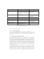
Heater Location
Reservoir
Cylinder
Line
Resistance [Ω]
12
9.1
30
Table 1: Resistance per Type of Heater
All heaters are floating and should not be grounded. You should know that also
for safety precautions - don’t touch any of the wires!
25
5.1.1
Reservoir and Cylinder Heaters
The reservoir heaters are connected in series so the overall resistance of the reservoir
V olt
is 24 Ω. The max current that the reservoir will draw is Imax = 120
= 5 Amp and
24 Ohm
the max power will be Pmax = Imax × 120 V olt = 600 W att. Each one of the heaters
is rated for a power value of 1200 W . In our calculation each one of the reservoir
heaters took about 300 W .
You can already see that there is no problem in operating the reservoir heaters in
series. The max power is much lower than the rated power and the max current is too
low to blow a fuse. This is true for the reservoir heaters when they are connected in
series. If they were connected in parallel then the story would be different and they
would reach the rated power value. Before it would happen the current will blow a
fuse. You now see how important it is to connect the heaters on both the reservoir
and cylinder in the right configuration.
In Fig. 18 you can see a basic schematics of both heaters as simple resistors.
Figure 18: Heaters Configuration for the Reservoir and Cylinder
The figure also shows you how to physically connect the heaters. Use the copper
jumper, it should be on both the reservoir and cylinder. Even though there are two
sockets for the cylinder you should only be using one for a ’heaters in series’ connection. The heaters should be placed on the copper foil that is on the reservoir and
cylinder.
My advice to you is to connect the heaters on the reservoir and cylinder in series.
5.1.2
Line Heaters
The line heaters are the coiled heaters in Fig. 15. They should be coiled around the
pipe line both on the reservoir line and the thruster line. Much like the band heaters
the line heaters have a constant resistance and the power to the them is controlled
from the line variac. Since there are 8 line heaters and they are all connected to the
26
same variac then they cannot all be connected in parallel or in series. The line heaters
electrical configuration is presented in Fig. 20. The reason why they are connected
like that will be given shortly. Moreover, in order to be able to separately control
the heaters on the reservoir line and thruster line there are two switches that open
and close the connections to the heaters. The panel is shown in Fig. 19 and the two
switches are circled.
Figure 19: Line Heaters Control Panel
Now, lets see why it is very inefficient to connect all the line heaters either in parallel or in series. if you have read the previous section you know that if all the heaters
are connected in parallel there might be an overloading problem and this is indeed
the case. The max percentage you can raise the line variac is somewhere around 35%.
Lets run the calculation. 8 heaters all are rated to 30 Ω and all are in parallel to
= 3.75 Ω. With a max voltage of 120 V
each other. Total resistance is Rtotal = 30
8
V
the max current will be Imax = 120
= 34.3 Amp. Clearly no fuse can withstand
3.5 Ω
this. Since the fuse of the line variac can take up to 12 Amp then the voltage should
be raised to about third of the possible maximum. The power that each one of the
heaters take will be low since each one drains 81 of the current. We see that a purely
parallel configuration is not good. The same goes with a purely series configuration.
We just won’t have enough voltage and the current on each heater will be fairly low.
The configuration from Fig. 20 was made so that the max voltage will be reached with
the max current. Normally you would want to run 6 line heaters, 3 in each branch.
The equivalent resistance for that is given in:
1
1 −1
1
1
1 −1
1
+
+
) +(
+
+
) = 20 Ω
(2)
30
30
30
30
30
30
If we add the RL heater the equivalent resistance will be 12 Ω. This tells us that
V
the max current for all heaters will be 120
= 10 Amp which is less than what12 Ω
ever the fuse can take. In case we operate just the TL heaters then the max voltage
V
will be 120
= 6 Amp which means that we can go with the variac up to 50%. That
20 Ω
is much better than the 35% of pure parallel connection as it was before October 2008.
Req = (
The heaters die once in a while and when this happens they tend to either be
shorted and act like a wire or just be grounded. Just check the resistance of the
heaters once in a while as well as the fact that there is infinite resistivity between the
connections and the heater sheath. When one of the heaters gets grounded during an
experiment you will see the thermocouple readings go crazy. It happens because the
27
Figure 20: Line Heaters Configuration
current flows into the tank through the heater sheath and also through the thermocouple protection circuit board.
Replacing the heaters is an expensive thing. The band heaters are about $60 each
while the line heaters are about $250 (!!!!) each. So treat them carefully.
5.1.3
Part Numbers for Ordering
Reservoir Heater: Watlow, st. Louis, 120V, 1200W, 0512, Part Number: MB03J2AP-3016
Cylinder Heater: Watlow, st. Louis, 120V, 1500W, 0512, Part Number: MB02J2AP-3004
600 Coil Heater: Watlow, st. Louis, 120V, 509W, 0419, Part Number: 125DC080AX-1421
400 Coil Heater: Watlow, st. Louis, 120V, 493W, 0120, Part Number: 125DC053AX-1422
Distributer: Critides Technical Associates (CTA). (201)868-4300
Fuse for Variac, 120 V , 8 Amp: Stock Room Item
Fuse for Variac, 120 V , 12 Amp: Stock Room Item
Fuse for Power Strip, 120 V , 15 Amp: Stock Room Item
28
5.2
Thermocouples
The thermocouples (TCs) take the temperature readings for the entire system and
therefore play a very important role. The thermocouples are places in various places
all around the feed system and thrust stand so the operator can properly monitor the
lithium’s location and the injection procedure.
There are two types of thermocouples: K-type and T-type.
The K-type thermocouples have either a yellow base or a ceramic white base. Its temperature range is −250◦ C to 1250◦ C (More details can be found in Appendix????).
There are 8 K-type thermocouples and they are placed in various places along the feed
system. Their positions are shown in Fig. ??. As you can see the TCs are located at
the most important locations for lithium position tracking.
1. Res TC - Tracks the reservoir’s bottom part temperature. indicates the necessary temperature change for melting down the lithium ingot.
2. RL TC - Tracks the
All types of thermocouples used in the system are shown in Fig. 21.
Figure 21: All Types of Thermocouples Used in the System
Figure 22: Bayonet Assembly Clamp for the Reservoir Thermocouple
5.2.1
Part Numbers for Ordering
Omega Account: ’Omega’, www.Omega.com, User Name: ’Danidin’, Password: ’a1s2d3’
K-type TC (Regular): ’Omega’, Part Number: SCAXL-125U-6-SHX, Price: $38.5 (OCT 2009)
K-type TC (Piston): ’Omega’, Part Number: SCASS-062U-18-SHX, Price: $37.1 (OCT 2009)
29
T-type TC (Gallium Pots): ’Omega’, Part Number: SCPSS-062U-6, Price: $26 (OCT 2009)
C-type TC (High Temp’): ’Omega’, Part Number: XMO-W5R26-U-125-30-H-HX-6, Price: $261 (OCT
2009)
Connectors for C-type TC: ’Omega’, Part Number: NHX-C-M, Price: $9.75 (OCT 2009)
30
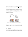
5.3
Thermocouple Protection Circuit Board
This component lies in the box next to the Labview box as seen in Fig. 23. The purpose
of this circuit board is to protect the sensitive Labview box from any possible electrical
damage that might occur during firing or operation of other subsystems. It would be
wise at this point to read a little bit about how a differential thermocouple works.
The main thing that is important to us is the fact that this kind of thermocouple
gives the voltage between points A and B (differential measurement). Both points can
be electrically floating at a certain potential yet we care about the potential between
them. The expected voltage between them is a few millivolts.
Figure 23: Thermocouple Protection Circuit Board Location
The protection circuit board comes between the thermocouple and the Labview
box.
The circuit board protects from the following:
1. Voltage over 0.6 Volts into the Labview box.
2. High frequency differential noise. That is noise between points C and D.
3. Current slip or current spikes.
4. Common mode drift. That is a voltage bias of both points A and B.
The circuit board consists of diodes, resistors and capacitors as seen in the circuit’s
schematics in Fig. 24.
The two types of diodes are limiting the output voltage to a maximum of 0.6 Volts.
Remember that we are expecting to get a few millivolts so that anything above 0.6
volts is definitely ”electrical crud”. The BAV21 diode is a slow reacting diode that
can deal with high current. The 1N4148 is a fast reacting diode (4 nSec). The capacitor, along with the 100K resistors, acts as a high frequency filter that keeps the high
frequency noise out. It takes care of the high frequency differential noise. The 1K
resistors are making sure that (d) will not happen by ”anchoring” the common mode
drift voltage to a certain value with respect to ground. In case of a high current spike
the diodes will take the damage instead of the Labview box.
The physical arrangement of the circuit’s component can be seen in Fig. 25.
If the circuit board is damaged it will have to be removed and some components
will have to be replaced. In the circuit board there are 20 terminals, or 20 mini circuits
31
Figure 24: Thermocouple Protection Circuit Board Schematics
as shown in Fig. 26. In other words there are many components. It is a very tedious
job to put one of these circuits together and you should try to fix the old one before
putting together a new one.
In case there is a problem with the temperature readings it might be possible that
one of the circuit board’s component got fried due to high currents. Most likely the
components that sacrificed themselves were the diodes, check to see if they work. If
any component need to be replaced you will have to spend a few hours taking all
the connections apart. Take the circuit board out carefully and use the solder gun to
replace the components with new ones. The components are quite common and might
actually be in the lab. There are spare diodes in the steel tank’s folder in the black
cabinet behind Bob.
All the connections are labeled with numbers between 1 to 80. Don’t remove the labels.
In every connection’s row (out of the 4 rows) there is one empty spot that doesn’t have
any wire going into it. This is why you will not find a wire with a labeled number that
matches the spot’s location. For example, in the thermocouple side the numbers 53
and 73 are missing so there is an empty connection between 52 and 54 (and 72 and 74).
32
Figure 25: Thermocouple Protection Circuit Board Physical Arrangement
5.4
Water Cooling System
Fig. 27
5.4.1
Part Numbers for Ordering
Dowfrost: ’Hubbard Hall’
Teflon Tubing 1/2”OD,
Teflon Tubing 3/8”OD,
Teflon Tubing 1/4”OD,
(Wendy)
3/8”ID: McMaster Carr, Part Number: 51805k74, Price: $9.34 per foot
1/4”ID: McMaster Carr, Part Number: 51805k73, Price: $6.90 per foot
5/32”ID: McMaster Carr, Part Number: 51805k86, Price: $3.56 per foot
33
Figure 26: Thermocouple Protection Circuit Board
Figure 27: Water Cooling Valve Panel
5.5
Emergency Water Cooling System
Remember that the LiLFA system is quite complex. Some systems require high currents and generate extremely high levels of heat; other systems, such as the lithium
feed system, require heating as part of their operation. However, at the same time,
some components, such as the thrust stand, are extremely sensitive to heat and must
be kept at cooler temperatures for proper function.
The one key to this complex system is water. This experiment employs an array of
water cooling hoses that snake their way through just about every component of the
system. Monitoring and controlling proper water flow is therefore key to maintaining
safe and proper functioning of the experiment. The two most important issues involving the cooling system are flow rate monitoring and leak detection.
The schematics of the emergency water cooling system is presented in Fig. 28.
The first issue that we will discuss here is the monitoring of proper water flow rate
in the system. In order to cool the system as necessary, the most important thing is
to maintain proper water flow. The water pump and flow gauges are all located on
the left side of the tank (closer to Eddie’s office).
The water valves and flow gauges are presented in Fig. 29.
The pump is operated with a simple switch which turns on the water flow. After
that, each particular branch of the system can be individually controlled by means of
34
Figure 28: Emergency Water Cooling System Schematics
inlet and outlet flow knobs. NOTE: Don’t close the outlet of any branch and leave
the inlet open - the water pressure will build up in the pipes and they will burst!
The water flow (g/min) is measure by the flow gauges for each individual branch of the
water supply system. As you will find by taking a look at the flow gauges, however,,
these gauges are somewhat imprecise and hard to read. Therefore, for the most critical
branch of the system, the feed system, we also employ electronic flow meters on the
inlet and return valves that help us insure proper flow.
The flow gauges are presented in Fig. 30.
The electronic flow meters output a voltage that corresponds to the flow rate. They
each have two outputs: one goes to Labview and allows us to monitor and record the
flow rate on the computer. The second output is connected to the flow control/water
leak detector box (the ”Brain”). The first important thing that this box does is sound
an alarm if the flow rate is too low, alerting us to a potentially dangerous or damaging
situation.
The water leak detector is presented in Fig. 31.
Now that we’ve introduced the flow control box, we can begin discussing the second important issue relating to the water cooling system: LEAKS! Remember that
Lithium is really dangerous, and can react violently with other materials, especiallywater! A leak in the water system can therefore result in an extremely dangerous
reaction between lithium and water. Leaks must therefore be detected as soon as
possible.
Which brings us to the second function of the flow control box. Besides monitoring
the water flow, the box also checks for differences in the inlet flow and return flow. If
35
Figure 29: Water System Valves and Flow Gauges
Figure 30: Water System Flow Gauges
the return flow is much lower than the inlet flow, then there is a leak in the system
somewhere along the way and the box will sound an alarm. The box then sends a
signal to a special membrane on the water supply line that immediately cuts off the
water flow, preventing any more water from entering the system and potentially reacting with the Lithium.
The Emergency Shutoff Valve is presented in Fig. 32.
Recall also that the lithium is melted and evaporated by a series of heaters before
it is injected into the thruster. If there is a leak in the water system, besides shutting
off the water flow, the fastest way to ensure that Lithium will not react with the water
is to shut off the heaters on the feed system. This causes the Lithium to cool and
solidify inside the feed lines, ”freezing” it in place (much in the same way that the
copper valves on the thruster and reservoir lines work). Therefore, if a leak does occur,
the box must also ensure that the heaters on the feed system are shut off.
In order to do this, we plug two important heaters, the line heaters and reservoir
heaters, into a special power box that is connected to the Brain. When a leak is
36
Figure 31: Water Leak Detector
Figure 32: Emergency Shutoff Valve
detected, the box sends a signal that cuts off the power box, thereby turning off the
heaters and causing the Lithium to cool and cease flowing, thereby saving your life.
The Emergency Shutoff Box is presented in Fig. 33.
Figure 33: Emergency Shutoff Box
Technical Notes
1. The electronic Flow Gauges were manufactured by ’Malema’ Sensors, and a copy
of the user manual can be found in the lab materials.
2. In order to trigger the Low Flow alarm, the water flow rate must be below 10
g/s and for both flow gauges.
3. In order to trigger the Water Leak alarm, the difference between the inlet and
return flows must be about 7-8 g/s. This difference must be maintained for a
37
few seconds in order to trigger the alarm.
4. After leak is detected there is a delay time until the power to the heaters is shut
off. The nominal working point should be 12 seconds. The delay time is set
from the water leak detector.
5. A low water flow or leak in any part of the system can be really dangerous.
However, our detection system is only connected to the feed system water line.
It is therefore recommended to keep an eye on the manual flow gauges for all
water systems while the experiment is being conducted.
6. The flow rate values as displayed on ’Labview’ have a discrepancy of about 2 g/s.
It’s not clear what causes this difference. The flow gauges may be somewhat
clogged or dirty, which would cause a slight error in the output.
38
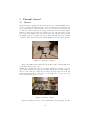
6
6.1
Thruster Operation
Current Reading
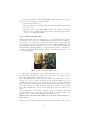
One of the most important parameters that is being measured during a thruster operation is the total current flowing through the anode and the cathode. This current
is also symbolized by the letter J.
In addition to the total current there are two more important current lines, the cathode heater current and the solenoid.
Since all three current lines deliver current in the range of hundreds of amperes they
can all be measured in the same way and with the same type of sensors.
The current is measured by a current sensor made by ’F.W.Bell’. All the three current
sensors are located on top of the tank and before the inlet point of the current lines
into the tank (Fig. 34).
Figure 34: Current Sensors for all 3 current lines. Left: Anode current sensor.
Middle: Solenoid current sensor, Right: Cathode heater current sensor
The type of the current sensors are:
Important Remark: The anode current sensor (measures the total current) has a
voltage divider located in the LabView box that is next to the computer station. The
voltage divider was placed in order to reduce the voltage by a factor of 2. This is why
the output function that gives the measured current by the ’Bell’ sensors is multiplied
by a factor of 2.09.
If for some reason you feel the need to calibrate the current sensor you can do the
following. Remove the current sensor from the anode line. Place the sensor on the
line of the cathode heater. Connect a dummy high power resistor to the leads of
the cathode heater current lines. Run current into the resistor while monitoring the
current reading of the ’Bell’ sensor. Compare the reading with the current reading of
the power supply. If the two readings match then there is no need for a recalibration.
If the two readings don’t match then change the 2.09 factor to the right value and
document that in this manual.
The last current sensor testing was done on 12 Jan 2010. The factor of 2.09 was verified to still be valid.
39
6.2
Preparation for Firing
Before the firing there is a check list that the operator has to go through. Using this
check list you will assure that everything is examined before the firing. This will minimize your chance for failures and errors.
It is very important to keep the order of the list.
1. Tank Cleaning - Clean up the tank from the inside. Clean all aluminum foil
leftovers, bolts, tools and dust. Dust also makes it hard on the pumping system
to pump down so cleaning off the dust with a vacuum clear is a very important
task.
2. Pumping System Testing - Test the capability of the pumping system by pumping down to the lowest pressure possible. Track the time it takes for the system
to pump down. Usually it takes time for the roots blower to pump down to low
enough pressure values so the diffusion pump kicks in easily.
In general, the tank should be as much as possible under vacuum and vented
up only for feed system installation or other preparations for the experiment.
3. Feed System Installation 4. Cooling Water Testing 5. Actuator Testing 6. LVDT Testing 7. Actuator Testing 8. Heaters Testing 9. GloveBox Preparation -
6.2.1
Part Numbers for Ordering
Aluminum Foil for Walls: McMaster Carr, Part Number: 9060k18, Type: Alloy
1000, Length: 250’
Magnets for Walls: McMaster Carr, Part Number: 5769k22, Type: Increased Pull
Boron-Nitride Aerosol Spray: McMaster Carr, Part Number: 10515k35, Price:
$38.68 (JAN 2010)
40
6.3
6.3.1
Check List
Preliminary Checks
Thermocouples
◦ Check by eye that all 8 thermocouples are in place
◦ Check with multimeter that all thermocouples are ungrounded
Heaters
◦ Check with the multimeter the resistance of each heater
−
−
−
−
8
2
2
1
line heaters (' 30Ω)
Reservoir heaters (' 20Ω)
Cylinder heaters (' 20Ω)
Valve heater (' 50Ω)
Piston
◦ Piston moves freely from 0 mm to 150 mm and back
◦ Labview output position matches the indication of the ruler on the piston
motor
Argon Flow
◦ Argon flows only through the reservoir’s argon line when vent valve is
closed
◦ Argon flows through both the reservoir’s argon line and the open line when
vent valve is open
◦ Attach the reservoir’s argon line to check if all lines are clear (argon flow
comes out off the cathode’s tip)
41
7
Thrust Measurement System
42
8
8.1
8.1.1
Vacuum System
Pumps
Short Background
The lithium tank’s Pumps’ system is illustrated in Fig. 36. As you can see the vacuum system contains 3 pumps: the ‘Roughing Pump’, the ‘Roots Blower’ and the
‘Diffusion Pump’. Each one of the pumps can operate in different pressure regimes
and is turned on simply by turning the right switches on. The ‘Roughing Pump’ is a
common mechanical pump and has to be operated first. The ‘Roots Blower’ is also a
mechanical pump that operates in a different way, which is not important for us. The
’Roots Blower’ can start its operation at low pressure (less than 5 Torr) and gets the
tank down to pressure values of 0.1 Torr quite fast. The ‘Diffusion Pump’ works with
a special type of oil that ”flushes down” the air molecules at very low pressure (few
mTorr). Since its operation includes evaporation of the oil it will start functioning at
around 250◦ c.
Figure 35: The Three Pumps. Roughing Pump, Roots Blower and Diffusion
Pump (Left to Right)
In Tab. 2 you can see the lower pressure limits that each one of the pumps can
reach.
Pump Type
Roughing Pump
Roots Blower
Diffusion Pump
Pressure [Torr]
0.5
20 × 10−3
10−5
Table 2: Lower Pressure Values for Each Pump Type
The tank’s vent valve is located on the side of the tank close to the computer
station. In Fig. 43 you can see the venting valve in a ‘closed’ position.
One more thing that you have to know before pumping down. Since you are working with lithium that is getting pumped down to the outside you need to make sure
that there is no oxygen in the pumping line. To do that you need to flood the line
43
Figure 36: Vacuum System Schematics
Figure 37: ‘Vent Valve’ on tank
with nitrogen from the ’Nitrogen Purge Valve’ (Fig. 38). It is located as follows: when
opening the basement door you turn right and walk to the wall. The ’Nitrogen Purge
Valve’ will be just in front of you on the wall (as in Fig. 38) and labeled. Open the
valve that slightly until you hear a ”hisss”. That should do.
8.1.2
Pumping Down Sequence
The Pumping Down Sequence is very important since if you do not follow it you might
damage the vacuum system. It is advisable that the first time you pump down Bob
explains to you what to do, or more importantly what not to do. Follow these steps
carefully and monitor the pressure display and ‘Diffusion Pump’ temperature carefully.
The pumping down process is done by using the switches on the control panel next
to the white tank. The panel with its switches is shown in Fig. 39. The bottom left
44
Figure 38: Nitrogen Purge Valve
circle shows the buttons for the ’Roughing Pump’ and the ’Diffusion Pump’. The next
circle in the bottom center shows the display for the ’Diffusion Pump’. The top circle
shows the switch for the ’Roots Blower’.
Figure 39: Control Panel for the Vacuum System
The operation is very simple: turn on or off the pumps by using the switches while
remembering that ‘on’ for the two valve switches means that the valve is open and air
can flow freely in the pipes. The pumping down sequence is given in table 3
The full instruction sheet for the pumping sequence is located on the side of the
pumps control panel cabinet. Use it.
In order to monitor the pressure there is a pressure gauge located at the rear of
the tank. It is also connected to the Labview software so that you can monitor the
45
When
Whenever your heart desires
Next
Next
Operation
seal the tank
Check oil levels of all 3 pumps,
cooling water’s flow rate in the
basement and open the Nitrogen
Purge Valve
stop quenching coil’s water flow
Next
Next
Pressure goes balow 5 T orr
Next
Open the ’High Vacuum Valve’
Turn on ‘Roughing Pump’
Turn on the ‘Roots Blower’
Turn on the ‘Diffusion Pump’
Next
During your work
Free to work
Monitor that temperature
stays under 290◦ c
Remarks
The basement key is in
the key box
close ‘Supply’ then ‘Return’
and then open the small tap
(see Fig. 40)
It will really start
functioning at 250◦ c
leave everything on
Table 3: Pumping Down Sequence
pressure directly from the computer.
8.1.3
Venting up Sequence
After you are done with all the measurements and work on the tank it’s time to vent
it up. Unfortunately venting up is not just turning off the pumps because you will
have to wait for the ‘Diffusion Pump’ to cool down. In Tab. 4 the venting up process
is presented.
8.1.4
Thermostat for Roughing Pump
One of the safety mechanisms that protects the roughing pump from over heating is a
thermostat (Fig. 41) that is attached to the roughing pump’s body. The thermostat
is meant to stop the pump from working when the body temperature reaches about
190◦ F . This temperature is much higher than the normal operational temperature of
the pump which is 120◦ F . When the thermostat ”senses” a temperature greater than
190◦ F it turns off all the 3 pumps in the system. When this happens the pumps are
completely turned off and even the red ”off” light will not be lit. The pumps will stay
off until the temperature goes down below 190◦ F and the red ”off” light will come
back. None of the pumps will come back and you will need to turn them on again in
the right procedure.
The temperature threshold of the thermostat can be readjusted by opening it
up and turning a screw that is in it. The screw is located right in the back of the
thermostat. Turn the screw CCW about half a turn for every 40◦ F you want to
increase the threshold by. You should check that the temperature threshold indeed
reached the new value by turning on the roughing pump, heating a beaker with water
46
Figure 40: The Quenching Coils
When
Whenever your heart desires
Next
Operation
Turn off ‘Diffusion Pump’
Start quenching coil’s water
flow
‘Diffusion Pump’ temperature goes
under 150◦ c
Next
After 1 minute
Next
Next
Turn off ‘Roots Blower’
Close the ’High Vacuum Valve’
Turn off ‘Roughing Pump’
Open the ‘Roughing Valve’
Open the ‘Vent Valve’ on the
tank and close the Nitrogen
Purge Valve
Remarks
close the small tap then
open ‘Return’ and then
‘Supply’
It will make a loud noise.
don’t be afraid to open the
valve all the way
Table 4: Venting Up Sequence
and sticking the thermostat in it. The pump would stop working when the new
threshold is reached.
47
Figure 41: The Roughing Pump Thermostat
8.2
Pressure Gauges
Pressure is really important. Since the thrusters are designed for use in space, they
must be tested in an environment that simulates space conditions. This means that
our thruster experiments must be carried out in a vacuum.
In order to ensure that we operate under vacuum conditions, we employ two types of
pressure sensors: a Convectron gauge and a Cold Cathode gauge. First we’ll describe
the operation of the Convectron gauge:
As the pressure is lowered in the tank, the temperature also drops, largely due to heat
transferred by convection to the air molecules that are rushing out of the tank. The
Convectron gauge has a very small wire that is exposed to the inside of the tank. As
the air around the wire is pumped out, the wire’s temperature begins to drop. This
change in temperature is detected by the gauge based on changes in the resistance of
the wire.
The sensor determines the pressure that corresponds to the observed temperature
change, which is displayed on the Display Box. Additionally, the gauge outputs a
voltage signal to Labview so the pressure can be recorded on the computer.
The output signal of the gauge is based on the equation V = 12 Log10 (P ), or
P = 102 V . The computer adds this input voltage to a small offset and then uses the
function to calculate the corresponding pressure reading from the gauge.
Technical Notes
48
Figure 42: Convectron Gauge Display
1. The Convectron Gauge has a range of about 1 mTorr - 1000 Torr. Below 1
mTorr, we rely on the Cold Cathode pressure gauge for our pressure readings.
2. Calibration of the gauge is very simple. Press ”Select” on the gauge display until
the ATM (atmospheric pressure) light is flashing. Set the display to the correct
pressure using the ”Higher” and ”Lower” buttons. Then pump the tank down
to vacuum and press ”Select” again on the display until the VAC (vacuum) light
is flashing. Set the display to 0.
3. It has been observed that the Convectron Gauge Display Box is really ”flaky”, or
noisy; pressure readings at atmospheric pressure display high degrees of variation
(650-825 torr). However, at low pressures, this noise is greatly reduced, and the
pressure readings are much more reliable.
4. We’ve also found that Labview’s calculation of the pressure is incorrect for atmospheric readings. This may be related to problems in the internal circuitry
of the gauge that result in an incorrect voltage output to the computer. Again,
though, this deviation is reduced at vacuum pressures.
5. For a reliable pressure reading at atmospheric pressure, check http://delta.princeton.edu/.
For low pressures, the Convectron Gauge can be depended upon. Below 1 mtorr,
the Cold Cathode Gauge is very reliable.
6. Make sure the Convectron Gauge is perfectly horizontal! If not, as the pressure
is lowered, the temperature changes in the wire will be off and you’ll get incorrect
readings!
7. The Convectron Gauge used in this experiment was manufactured by Terranova.
The user manual can be found in the lab with the rest of the lithium information
and material.
49
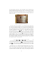
8.3
Fire Vent
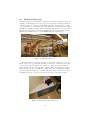
The Fire Vent (or Venting Valve) is located on the side of the tank as shown in Fig. 43.
There isn’t much to say about the Fire Vent since it is just a valve. The valve is opened
by rotating the knob in the CCW direction. By doing that you will let air into the
tank from the bottom rear part of it.
Figure 43: Fire Vent
It is very important to remember not to open the valve all at once but slowly and
gradually. If you don’t do so you will risk tearing its O-rings apart. Sometimes it will
just happen after a while and a leak might start at the valve. If this is the case you
will have to take it apart, replace and grease the O-rings. In Fig. 44 you can see how
the valve should be taken apart. Don’t disconnect or take apart other parts. The vent
pipe that goes into the tank is pretty thin and might actually break if you jilt it too
much.
First thing you have to do is to take a screwdriver and take out the ring that holds
the cylindrical part of the valve. It is metallic and can be seen in Fig. 44 right next
to the cylindrical part. The ring is placed in the back of the valve. After taking that
ring out you can just pull the valve out. Now it should look exactly like in the picture.
On the cylindrical part of the valve there are 3 O-rings. Two are placed in the same
direction whereas the third O-ring is placed in the center. The central O-ring is the
one that is usually teared apart. It is a 2-215 size O-ring. My advice is to take all the
O-rings out, clean the valve with acetone, clean/grease the O-rings and put everything
back in place. After doing that there won’t be any good reason for having air leaking
in from the vent valve.
Figure 44: The Fire Vent After Being Taken Apart
50
8.3.1
Part Numbers for Ordering
Center O-ring: 2-215 O-ring, Stock Room item
Side O-rings:
51
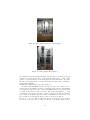
9
9.1
9.1.1
Lithium Handling
Glove Box
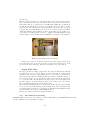
Short Background
The Glove Box is the small vacuum chamber and is located in the corner of the lab
right next to the main tank. You can see a nice picture of it in Fig. 45. The Glove
Box’es purpose is to give a good environment for lithium loading. Basically you fill the
glove box with argon instead of air and you now have a good and clean environment
for working with lithium. So far it sounds quite simple (But it is not).
Figure 45: The Glove Box
The glove box contains 3 chambers (schematics in Fig. 46): The Main Chamber
(MC), the Ante Chamber (AC) and the Glove Port (GP). The Main Chamber is where
everything is happening and in it you will deal with the lithium. The pressure in the
main chamber should be as close as possible, but a little higher than the atmospheric
pressure so to make sure that air will not leak into the tank in case of a leak. Also,
in case you are working with the gloves and the pressure in the MC is a little lower
than 1 atmosphere then the gloves will start inflating in the MC. Remember, pressure
difference on rubber will inflate it and eventually blow it up.
The Ante Chamber is the little chamber to the right of the MC. Its purpose is to
enable us to get things into the MC without the need to expose it to air.
The way it is done is given in this section.
The Glove port is the space within the gloves and the space that connects both of
them. If the gloves are not covered then the glove port is exposed to air and it is in
atmospheric pressure. Never expose the glove port to air when the Main Chamber is
under vacuum. The pressure difference will inflate the gloves and blow them up!
The glove box has quite a lot of knobs and valves. The pictures of the valves and
their names are given in Fig. 47.
Always make sure that you open and close the right valves when working with the
Glove Box otherwise you might create pressure differences or get air into the Main
Chamber with the lithium. The process of loading the lithium into the glove box and
52
Figure 46: Glove Box Diagram
Figure 47: Valves on the Glove Box
inserting tools through the Ante Chamber is hanged on the wall to the right of the
glove box. You can see there with colors which valve has to be open at each stage.
Just in case I will go over the procedure in more details here.
The Glove Box’es pump is a ’KC8’ ’Kinney’ high vacuum pump. The spec sheet
and the user manual can be found in the appendix section. The pump requires ’AX
high vacuum oil’ (spec sheet is also attached in the appendix section).
9.1.2
Working Procedure
In order to work in the glove box you need to do the following:
1. Place all the needed tools in the Main Chamber.
2. Secure the Glove Ports covers.
53
3. Check the pump’s oil level.
4. Open the 4 main valves (VAC1, MC1, AC1, GP1) while keeping the two venting
valves closed.
5. Turn on the pump the watch the pressure go down. It should take about 40
minutes to pump down under 100mT.
(It is advisable that before you put lithium in the glove box you make sure that
the glove box can take the pressure down to under 100mT and see that it does
it within a reasonable time).
6. Once the pressure is low enough close VAC1. Now the pump is isolated from
the rest of the glove box and the pressure should not change. If the pressure
starts going up it means that you have a leak and cannot continue working with
the glove box until you fix it.
7. Start injecting Ar into the glove box through the Main Chamber and the Ante
chamber. Notice that they are still connected through the pumping line so the
pressure will be the same in both. The same thing is true also for the Glove
Port.
8. Keep the Ar flowing until you reach 1atm of Ar in all of the Glove Box chambers.
9. Close all valves (close MC1, AC1 and GP1) and open the covers from the Glove
Port. Notice that if the pressure in the main chamber is higher than 1atm the
gloves will pop out towards you when you open the Glove Port covers, so be
careful.
10. Now you can work freely with lithium. Make sure that the other guy that works
with you keeps an argon pressure of slightly over 1atm so in case of leaks Ar
will flow out of the Glove Box instead of air flowing in.
9.1.3
Using the Ante Chamber
Lets say you remember that you forgot to put a tool in the Main Chamber before
pumping it down and now you are in the middle of working with lithium. This is what
the Ante Chamber is for. This is what you do:
1. Secure the door between the MC and the AC.
2. Make sure that the AC is in atmospheric pressure.
3. Open the Ac door.
4. Place in the AC the tool that you want to get into the MC.
5. Make sure that the MC1 valve and the GP1 valve are closed. Make sure that
the AC1 valve and the VAC1 valve are open.
6. Turn on the pump and pump down the AC for at least 10 minutes.
7. Close the AC1 and VAC1 valves.
8. Open the Ar valve on the AC until it reaches 1 atmosphere of Ar.
9. Open the door between the MC and the AC and get your tool into the MC.
10. You are good to work with the tool now. Don’t forget to make sure that the
pressure in the MC is slightly higher than 1 atmosphere.
54
So you have just finished working with the lithium and it is in the reservoir. Getting
the reservoir out of the Glove Box is fairly simple:
1. Open the Ante Chamber door.
2. Make sure that Ar is constantly flowing into the Ante chamber (even though
the door is open).
3. Open the door between the Main Chamber and the Ante Chamber and quickly
take the reservoir out while trying to keep it under constant Ar flow from a tube
connected to an additional Ar tank.
9.1.4
Leaks in the Glove Box
In the ideal state there will be no leaks in the glove box. Unfortunately it is never the
case and the best you can do is to minimize the leaks. Remember that you will need
to use the glove box for any period of time between half an hour to a few hours (first
time I used it it took me 2.5 hours). The best check for leaks is inflating the gloves
outwards while closing VAC1 and GP1. The glove box is filled with argon while and
the main chamber and ante chamber are connected. The whole glove box should look
as in Fig. 48. In order to inflate the gloves you use only a little bit of argon so don’t
worry about finishing it.
Figure 48: Glove Box with Inflated Gloves
If the gloves stay straight for about 30 minutes then the glove box is good to be
used. Since there will always be a small leak it is important to keep positive pressure
in the main chamber while working in the glove box.
The most prominent place to have leaks is around the gloves where they connect to
the glove port. In case you have a leak put your ear against the inflated gloves, you
should hear the leak. The gloves are connected to the glove port by a metal ring that
pushes against them. In the past I had many leaking problems at that spot so I added
an O-ring to the ring so to push on the rim of the gloves even more. It worked and
that’s what you’ll find if you remove the metal ring. Do not remove it if there are no
leaks!
The next place where you might have leaks is the valves, especially MC1. Fixing this
problem is simple, just open the valves up and clean all the parts from within. You
might also need to replace the O-ring that’s there with a new one.
(I don’t know what the O-ring number is. If you get it then add it up to
this manual.)
Other places that might have leaks are the electrical socket that’s on the left side
55
of the glove box, the door between the main chamber and the ante chamber and the
back plate. All of these are quite unlikely though.
9.1.5
Tips, ”Musts” and ”No Nos”
Some tips, ”Musts” and ”No Nos” for working with the Glove Box:
•
Always always always have 2 people working on the Glove Box. While one
person has his 2 hands in the Gloves the other one monitors the pressure in the
Main Chamber and keeps the pressure slightly higher than atmospheric pressure.
• I wrote it here about a million times but remember that it is very easy to blow
up the gloves. Monitor the pressure in the Main Chamber and the Glove Port
and think before opening or closing any valve.
• Make sure that there is no water in the Glove Box before placing the lithium
in it.
• Half an ingot is about 130gr and is sufficient to fill up the cylinder all the way.
In order to cut the lithium you can and should use a big hammer and a chisel
(I’m not kidding).
• Unused lithium goes into one of the small white buckets (Fig. ??) and immersed
in mineral oil. Close the bucket firmly in 1atm of Ar and take it out in the same
way you are taking the reservoir out. In order to get rid of the mineral oil the
next time you want to load the rest of the lithium then use Hexane.
Figure 49: Pail for Lithium Leftovers
•
In case anything happens make sure that you know where the graphite fire
extinguisher is. Make sure that the pump is on while handling lithium outside
of the Glove Box. If something happens you can quickly through the lithium
into the Glove Box and pump down while injecting Ar.
• Before putting your hands in the GP gloves make sure that you have cotton
gloves on. The cotton gloves make sure that your hands don’t stick to the GP
gloves.
• Always load the lithium under 100mT or less. It takes about 45 minutes to pump
down the Glove Box to under 100mT (Last time I checked it on September 2008).
56
You should measure this just before the first time you work on the Glove Box.
Just put a convectron gauge instead of the bourdon gauge (round diaphragm
gauge), pump down and see how long it takes the pressure to get under 100mT.
9.1.6
Part Numbers for Ordering
Gloves for Glove Ports: ’North’, Part Number: 8N3032, Size: 9Q. Price: $125 (June 2008), Distributer:
’Durawear’
Mineral Oil: Bought in CVS, it is sold in 32oz and 16oz bottles
Cotton Gloves: McMaster Carr, Part Number: 5452T13, Size: Large
Small White Pail (1/2 Gallon): McMaster Carr, Part Number: 40015T61
Big White Pail (1 Gallon): McMaster Carr, Part Number: 40015T62
AX Pump Oil: Purchased from ’http://www.usvacuumpumps.com’, 1 Gallon is $45 (Jan 2010)
57
9.2
9.2.1
Lithium Cleaning
Main Dangers
We will start this chapter with an equation that represents a chemical reaction:
1
H2 + 508 kJ/mol
(3)
2
Eq. 3 shows us what happens when you mix up pure lithium with water. Basically
you get 3 products, lithium hydroxide, pure hydrogen and heat. All of the 3 products
are dangerous in different ways and you should be fully aware of it for your own health
and others in the lab. This is why the beginning of this chapter will be dedicated not
to cleaning but to understanding the dangers of lithium.
Li + H2 O → LiOH +
Lithium hydroxide comes in a form of a white dusty powder as shown in
Fig. 50. It is very corrosive and dangerous. You should not, under any circumstances,
breathe/taste/touch lithium hydroxide. If you see white powder in the tank remove
it with a moist towel and throw the towel away into a hazardous waste bag. You will
see in this chapter that after cleaning up the feed system from lithium you will end up
with a tub filled with water and lithium hydroxide. If for some reason you put your
hand in the water for a few seconds and take it out it will be oily like. This is because
the oil-like material is your dissolved skin. If you put your hand a little longer in the
water it will start bleeding cause the lithium ate through the skin. If you haven’t
taken lithium seriously so far I hope that now you will.
Figure 50: Lithium Hydroxide
Hydrogen is probably the most dangerous product out of all 3 products from
above. The reason for that is that hydrogen explodes. It explodes if it has a concentration of 4% to about 75% in air. If you take a big chunk of lithium and just spray
water all over it then it will release a lot of hydrogen very fast and eventually explode.
In the ’Hydrogen Detectors’ section you can read about how to know if you reach the
dangerous concentration of hydrogen in air.
Heat is as usual one of the problems in this system. When you put lithium in
water the chemical reaction heats the water up. It might heats up the water to the
state of boiling. This tells us that
(a) The water container should be made out of something that doesn’t melt at temperatures of less than about 150◦ C.
(b) The water should be constantly drawn to a hazardous waste drum and the tub
refilled with fresh cold water.
Just to show you how hot the water in the tub can get we will calculate the increase in water temperature in case we introduce a quarter of a lithium ingot into the
58
water. You might think of it as lithium leftovers in the reservoir.
Lets assume we have a tub with 20 Liters (20 × 10−3 m3 ) of water at a temperature
of 20◦ C (293 K). One quarter of a lithium ingot is about 80 gr (0.08 kg) which in
gr
molls will be 6.94180gr/mol
= 11.52 mol.
From Eq. 3 we know that each moll of lithium releases 508 kJ/mol so the overall
energy released in this chemical reaction is 11.52 mol × 508 kJ/mol ' 5.85 M J. That
is a whole lot of energy.
3
gr
' 1100 mol. (We will neglect the
Now to the water, 20 liters of water are 20×10
18 gr/mol
fact that some of the water’s mass is lost in favor of the chemical reaction since only
11.52 mol out of 1100 mol are lost in the reaction).
J
The specific heat capacity of water is cm = 4.184 gr×K
, which means that the heat
3
J
capacity of 20 liters is Cm = 4.184 gr×K × 20 × 10 = 83700 J/K.
The final step is calculating the temperature rise by using the total energy released
in the reaction and the heat capacity (assuming that it doesn’t change much between 20◦ C and 100◦ C). Etot = Cm × ∆T and the final temperature increase is:
6
J
∆T = Etot /Cm = 5.85×10
' 70◦ C.
83700 J/K
This calculation shows us that lithium leftovers in the resrvoir can raise the water
temperature from 20◦ C to 90◦ C!
You now see all the dangers that one chemical reaction might put you through. Unfortunately this reaction is one of many and there are other much less common dangers
that you might want to look at. In Appendix ???? you will find a general review on
the family of possible lithium reactions with common substances. Read it at least once
so you will know what to expect.
9.2.2
Preparation for Tank Opening
Before opening up the tank and cleaning it up you must make sure that you have all
the safety equipment on and it is working properly. You should look like in Fig. 51,
but tougher.
when you clean up the tank the following has to happen:
• No less than 2 people have to take part in the tank opening. They have to have
all the breathing equipment on along with full wear bunny suits.
• The two people that are doing the cleanup have to go through SCBA training.
This training is done by the university’s safety person in the e-quad.
• No one is allowed in the lower level. NO ONE!!! To make sure that this is the
case put signs on all the 3 doors that are leading to the lower level.
• While cleaning up the tank there must be at least one person outside of the tank
at all time. There should never be 2 people together inside the tank.
• At least one person stays in the upper level in case something is happening and
he needs to call 911. That person has to be fully aware that there is a tank
cleanup in progress.
The safety equipment is formed out of the following:
1. Bunny suits
2. SCBA breathing gear
59
Figure 51: Lithium Cleaning Person
3. Nitrile thin gloves (blue)
4. Nitrile thick gloves (black)
5. Graphite fire extinguisher
6. Fire resistant face masks
7. Fire resistant coats
8. Fire resistant gloves
All of the safety equipment is presented in Fig. 52 with corresponding numbers.
You don’t have to put on all the safety equipment. You will have to use it according to the type of cleanup that you are doing.
If you fired the thruster you have lithium hydroxide dust in the tank. For this you
will have to wear the breathing gear (SCBA) with the bunny suits.
Every time you have a big piece of lithium in the system or the tank you have a fire
hazard and you will have to wear the fire resistant gear.
Every cleanup you will have to remove the reservoir that has some lithium leftovers in
it. The guy that holds and removes the reservoir will have the fire resistant gear on
him, including the big gloves. The other guy will have the thin nitrile gloves on so he
can easily take the bolts out.
If you put your hands in water with lithium hydroxide you should have the thick black
nitrile gloves.
In general, always have at least one pair of the thin nitrile gloves on your hands no
matter what.
I hope that this is clear enough. If not then change the manual here so to make it
60
Figure 52: Safety Equipment
clearer.
The breathing air comes from two main air bottles, normally yellow bottles. Before every cleanup they have to be at least half full. If this is not the case then replace
one of them with a new one. The breathing air system is shown in Fig. 53. The bottom
regulator shows the air pressure that’s coming out of the bottle. The top regulator
shows the air pressure that goes to the air masks. It should be put on about 150 P SI
(CHECK THIS) and adjusted according to your convenience. The pressure should
be higher than your breathing rate so if there are leaks in the air mask air will flow
out of the mask to the out side instead of into the mask from the tank’s environment.
Figure 53: Breathing Air Bottles
61
Take a much better picture of the bottles with
the regulators
Before opening up the tank you have to prepare the following tools:
• Allan wrench with yellow handle
• Small allan wrench for the valve
• 9/1600 wrench
• 1/200 wrench
• Crescent wrench (all sizes)
• Flat-head screwdriver
• One metal pail for the bolts and nuts, one for the TCs and one for the magnets
• Sponges, paper towels, water squirt bottles and plastic garbage bags
• Vacuum cleaner (placed under the glove box)
After having all the necessary gear and tools the last step before opening up the
main tank door is to open the left side port cover and connect the yellow cloth flexible
air duct (the big yellow tube that Eddie usually puts in his office to suck the cigar
smell). You have connect the air duct so to suck the lithium hydroxide fumes that
were created when venting up the tank. The connection is done in a fairly primite
way, that is with lots of duct tape until the air duct doesn’t fall.
Now you are ready to open up the main tank door.
9.2.3
Taking the System Apart
First thing that you do after opening up the tank’s door is taking the feed system
out. The order in which you take the feed system apart is very important for your
safety and the integrity of the system for future use. In Fig. ?? you can see the disassembling procedure of the feed system. The steps are numbered starting from step 1.
1. Make sure that all power to subsystems is off, all temperatures are below 30◦ C
and water is not running in the system.
2. Disconnect all the thermocouples and get them out
3. Disconnect the heater connections to the heaters’ panel
4. Disconnect the power wires to the reservoir and cylinder
5. Very very carefully open the swagelok connection to the 16 inch feed tube (The
TL should now be supported only by the connection to the cylinder)
6. While one person holds the TL the other opens the swagelok connection to the
cylinder. If after opening it the TL doesn’t just drop it means that lithium is
holding it so jerk it a little bit until it gets released. Take the TL out carefully.
Place the TL near the glove box.
7. Open the 4 small allan screws of the valve. Move the valve off the RL so the
RL is free to be removed.
8. Open the two swagelok nuts that hold the RL. One to the reservoir and the
other to the cylinder. Remove the RL. Place the RL near the glove box.
62
9. One person holds the reservoir with the two fire resistant gloves while the ante
chamber of the glove box is open. The other person disconnects the argon feed
line to the reservoir. Afterwards he removes the bolts that clamp the reservoir
to the thrust stand. The reservoir is placed in the ante chamber until the parts
are placed in the water tub.
10. Disconnect the two water connections to the cylinder (It might get a little
messy). One person holds the cylinder with the fire resistant gloves while the
other person disconnects the bolts that clamp the cylinder to the thrust stand.
Make sure that the piston TC was removed. If you can reach the top part of the
piston try and rotate it so to unscrew it from the rod and releasing the piston
with the cylinder. If it isn’t possible then rotate the whole cylinder with the
stuck piston in it. It is the most tedious part and it has to be done slowly and
carefully. Do not let the piston fall into the cylinder, it might hit the lithium
and... well, you know the rest. Place the cylinder with the piston near the glove
box.
Add a set of pictures that shows the procedure.
Preferably from an actual cleaning. Put the pictures side by side in a sequence and numbered
At this point the feed system should be removed and placed in parts near the glove
box and in the ante chamber. One person should start taking care of taking the parts
completely apart and placing them in the water tub while the other person does the
joyful job of getting inside the tank and cleaning it up from within.
9.2.4
Lithium Removal
At this point the two people who clean up the tank are working separately, one inside
the tank and one outside.
For the inside cleaning you will need to prepare the vacuum cleaner and the garbage
can right on the verge of the tank. The garbage can should have regular plastic bags
that will eventually be labeled and disposed of properly. The person who is working
inside the tank is carefully taking off the aluminium foil from the walls. It should
be done carefully and slowly so the lithium hydroxide (white powder) stays on the
foil. The foil is folded inwards to keep the lithium hydroxide in it and thrown to the
garbage can. After taking all the aluminium foils out of the tank it should be cleaned
with a regular wet sponge. The sponge cleaning is done on all the spots where there
is lithium on the walls and around the thruster. The work inside the tank is the most
tedious one and should be done by the more experienced person out of the two.
For the outside cleaning you will need to fill the tub with water, place the the small
water pump in it and leave it off. The other end of the pump’s tube should be in
the 55 Gallon drum. The person who is working outside the tank is finishing to clean
the area where the feed system was located with paper towels and wet sponges. In
case there is some lithium leftovers around they should be thrown into the water tub.
After that he is taking the feed system’s piping apart with a pipe wrench and places
the pipes in the water tub. The pipes will start to bubble out hydrogen. Next thing
is waiting for the inside cleaner to finish his job and come out.
During all this time the outside person has a very important role - monitoring the air
63
supply. If you are running out of air completely (It should never ever happen if you
prepared right) you should close the tank and stop the cleanup.
Now it’s time to close the tank’s door, take the masks off and breathe.
It is not over yet.
Remove the yellow air duct from the tank and place it over the water tub. The cleanup
at this point should look like in Fig. 54.
Figure 54: Typical Feed System Cleanup by Using the Water Tub
Turn on the small water pump and in the same time inject water into the tub from
the water tube near the glove box.
Take the reservoir, open it and put it in the water tub. This might get a little dangerous and therefore should be done by only one person while the other one is standing
away. The same thing should later be done with the cylinder. Unfortunately, in most
cases it is impossible to take the piston out of the cylinder. It is clogged inside with
lithium. If this is the case when you will have to use the piston extractor.
What is this piston extractor you ask? Good question
The piston extractor is a ”middle ages” device that pulls the piston relative to the
cylinder. It is very hard for me to explain it with words so check out Fig. ??.
Put here a sequence of pictures that shows how
to use the piston extractor
After taking the piston out put it in the water tub with the cylinder. Be aware
of the fact that both the reservoir and the cylinder tend to release a lot of hydrogen
when put into water. If for some reason the hydrogen detectors turn on the alarm stop
any work that you are doing and make sure that the yellow air duct is over the water
tub and turned on. More about the hydrogen detectors in the ’Hydrogen Detectors’
section of this chapter.
9.2.5
Cathode Cleaning
Since the cathode is the most sensitive and expensive part of the thruster extra care
should be taken when removing the lithium off and from inside it. Once the thruster is
taken apart and the cathode is taken out the lithium must be cleared from the cathode
before the next firing. Remember, the thruster will not fire if the cathode is clogged.
Clearing the cathode from lithium is not an easy task and there are a few possible ways
64
of doing it. All ways are listed here starting from the easiest and least destructive ways.
1. Place the cathode in a pail with water. This method is similar to the method
used for the rest of the feed system pipes. The water will react with the lithium
while dissolving the lithium hydroxide. Hot water is more effective than cold
water.
This method usually doesn’t work and the lithium gets capped by lithium hydroxide in the narrow 1/800 Molybdenum TZM feed pipe.
2. Use a narrow rigid steel wire and push it into the clogged pipe. Do it under
water so that the lithium reacts with the water when exposed. Try to hand drill
in the tube with the steel wire. If the material in the tube feels sticky and soft it
is lithium. If the material in the tube feels rigid and rock-like then it is lithium
hydroxide.
3. Take the cathode up to Craig Arnold’s lab and put it in the oven. The code to
the lab is 253. Stick the cathode in the oven, place two copper foils to collect
the shit that comes out of the cathode and take the temperature up to 460◦ C.
At this temperature the lithium hydroxide starts to melt and will hopefully pure
out of the cathode and into the copper foil. Unfortunately this temperature is
also the temperature in which tungsten starts oxidizing and so don’t leave the
cathode in the oven for too long. Two hours should be sufficient. If the lithium
hydroxide doesn’t melt then you can raise the temperature a little bit further
up to 480◦ C.
Use the high temperature gloves when dealing with the cathode and let it cool
down for at least an hour before taking it out. It might turn somewhat bluegreen in color due to the oxidation.
4. Drill the lithium out. This method might be extremely dangerous and should
be done slowly and carefully and with protective gear on the hands and arms.
Very very carefully open the swagelok fitting that is on the end of the tube with
the cathode jig. The cathode jig is a simple rectangular box (labeled ’Cathode
Jig’ in the lithium cabinet) that holds the cathode while the torque can be put
on the swagelok. Just wrap the cathode jig around the cathode close to the
swagelok fitting and hold it in the vice. Now you can freely use wrenches to
open the swagelok fitting without having the danger of breaking the cathode
connection. Take a hand drill and put an 1/800 drill bit in it. The longer the
drill bit the better. Start drilling in the tube carefully. Once in a while take the
drill out and put it in water. After drilling a few millimeters into the tube you
might reach pure lithium. Stop drilling and try to put the cathode in hot water
to see if the water can clear it.
After clearing the lithium from the cathode use a pipe cleaner to clean the cathode
heater hole.
9.2.6
Part Numbers for Ordering
Bunny Suits: McMaster Carr, Part Number: 5231T39, Size: XXXL (Danny Size),
XXL (Justin Size), XL (Short People)
Nitrile Thin Gloves: Stock Room Item
Hazard Mats (Pink Mats): ’NewPig’, Part Number: MAT354, www.Newpig.com,
User Name: ’Danidin’, Password: ’a1s2d3’, Price: $91 (OCT 2008)
65
Water Pump (for tub): ’Little Giant Pump Company’, Oklahoma, Item Number:
526003, Model Number: NK-1, www.lgpc.com, Phone Number: 405-947-2511
66
9.3
Hydrogen Detectors
The Hydrogen detectors are the little boxes that are spread all around the lab and look
as in Fig. 55. The hydrogen detector’s job is to alert you if there is a high concentration
of hydrogen in the air. Hydrogen can be hazardous and present an explosion danger
at a concentration of over 4% in air. The lowest hazardous concentration is also called
the LEL (Lower Explosive Limit). The reason that we have hydrogen detectors in the
lab is the fact that when we clean up the tank and rinse the components in water the
lithium reacts with the water so to form lithium hydroxide and hydrogen.
Figure 55: Hydrogen Detector
The hydrogen detectors that you should be concerned about the most are the one
that is located on top of the tank as in Fig. 55 and detector that is located at the
bottom of the rear of the tank close to the water cooling system as seen in Fig. 56.
On the display of the detectors you will see a number that represents the percentage of
hydrogen in the air out of the LEL. For example, if the detector displays the number
50 it means that the hydrogen concentration in the air is 2%. If the detector shows
any number between −5 and 5 it is ok, the detectors are not perfectly accurate.
Figure 56: The Rear Hydrogen Detector
67
All of the detectors in the lab are connected to a main unit (Fig. 57). When any
of the detectors goes over 30% of the LEL an alarm will sound in the lab. If that
happens you stop everything and check to see what is the source of hydrogen. Don’t
be surprised if this happens right after you throw the lithium contaminated reservoir
into a tub with water. The alarm can be disabled only from the unit. In order to do
that follow the instructions on the unit (I can’t tell you how to do everything). In
case one of the detectors goes over 60% an ear piercing alarm will sound all over the
lab. If this happens evacuate the lab immediately and call 911!
Figure 57: Hydrogen Detector Unit
The last thing that you need to know about the hydrogen detectors is how to
calibrate them. Yes, they do need to be calibrated once in a while. For the calibration
you will need to get the calibration bottle from the store room (it is next to all the
other gas bottle at the corner of the room). The calibration bottle is shown in Fig. 58.
The calibration bottle contains 2% hydrogen so when the detectors are calibrated they
will show 50% when injecting gas from the bottle into them. When you check that
just remember that the first alarm will be sound. Just disable the alarm and continue
to the calibration.
The calibration process is done according to the instructions on page 11 of the manual
of the S104 unit. The manual should be attached to the end of this manual.
Figure 58: Hydrogen Detector Calibration Bottle
68
10
10.1
Argon Truster Operation
Sonic Orifice
The sonic orifice is the part in the thruster that enables you to control the argon mass
flow rate. The physics behind the sonic orifice is quite basic (see Fig. 59). It is a plate
with a tiny hole that is drilled in its center. The plate is placed in an NPT connection
so any gas flow within the NPT connection will flow through the tiny hole. The NPT
connections are connected in between the Argon valve and the tube that’s going into
the tank. Since the pressure difference is very large (about one atmosphere on one side
and vacuum on the other side) the flow will be a sonic flow. The male NPT connection
pushes the disk (gray disk in Fig. 59) and keeps it from moving. The 3 orange flexible
washers are there as a soft buffer between the male NPT connection and the disk.
This way the gas can flow only through the tiny hole.
Figure 59: Sonic Orifice Structure
We are interested in the mass flow rate so the relation between the hole size, the
sonic velocity and the mass flow rate is:
ṁ = ρAVs
(4)
√
The sonic speed (Vs ) is temperature dependent through Vs = γRT . The orifice’s
area (A) is known and the gas density (ρ) is pressure and temperature dependent
through the ideal gas law.
P − PT ank
(5)
RT
Remember that R is species dependent according to R = R0 /Mw . Also PT ank ' 0
Plugging Eq. 5 into Eq. 4 gives the following relation for ṁ:
ρ=
γ 1/2
(6)
RT
The temperature is measured by a thermocouple at the NPT connection and is
usually around T = 260 K because of the gas expansion.
The sonic orifice has a known area.
The mass flow rate is controlled by changing the pressure at the argon gauge side. It
ṁ = P A
69
can be controlled by the needle valve that’s on the argon flow panel.
The values of the different components are:
γAr = 5/3
RAr = 8314 J/(K × Kmol)/39.9 Kg/Kmol = 208 J/(Kg × K)
T ' 260 K
d0 = 0.48 × 10⁻³ m
P = 2 atm − 0.05 atm
ṁ = 5 × 10⁻⁶ Kg/sec − 200 × 10−6 Kg/sec
10.1.1
Part Numbers for Ordering
Stainless Steel Disks: Diameter = 0.500 , T hickness(Length) = 0.0100 , Distributer: ’McMaster Carr’,
Part number: 2895T51
70
11
Leaks
Leaks Leaks Leaks....... What a huge problem. I can’t even start explaining how many
hours I spent on trying to find leaks in the tank.
Bla bla bla
11.0.2
Part Numbers for Ordering
VacSeal (High Vacuum Leak Sealant): ’Space Environment Laboratories’, Website: http : //www.2spi.com/catalog/vac/vacleak.shtml, SPI#: 05051 − AB, Size:
16 oz, Price: $94 per can (JAN 2010)
71
12
Materials
Here you will find information on the different materials used in the system.
12.1
Lithium
Lithium is the propellant of the thruster. It is a metallic solid metal that is fairly soft
compared with aluminum or copper.
You can see a picture of a lithium ingot right before loading it into the reseervoir in
Fig. 60.
Figure 60: Half a Lithium Ingot
Properties:
Atomic Number: 3
Atomic Weight: 6.941 gr/mol
Phase: Solid
Density (Solid): 0.534 gr/cm3
Density (Liquid): 0.512 gr/cm3
Melting Temperature: 453.69 K
Boiling Temperature: 1615 K
Heat of Fusion: 3 kJ/mol
Heat of Vaporization: 147.1 kJ/mol
Crystal Structure: BCC (Body Centered Cubic)
1st Ionization Energy: 520.2 kJ/mol, 5.39 eV /atom
2nd Ionization Energy: 7298.1 kJ/mol, 75.8 eV /atom
3rd Ionization Energy: 11815 kJ/mol, 122.7 eV /atom
12.2
TZM
TZM stands for Titanium-Zirconium-Molybdenum. It contains 99.2% molybdenum,
0.6% titanium and 0.2% zirconium. It is a molybdenum alloy that shares most of its
properties with pure molybdenum yet has some great advantages compared to pure
molybdenum.
12.3
Macor
Macor is basically machinable ceramics. This fact makes it very expensive.
72
Figure 61: TZM Pipe of the Cathode
12.4
Part Numbers for Ordering
Lithium Ingots: ??????????
73
13
Troubleshooting
74
I believe that this is the most important chapter of all chapters in this manual.
After working on the lithium system for a while You will see that troubles and problems are all over the place. If you know what problems to expect you will know how
to prevent them from happening. If you know how to fix them you’ll be back on track
in no time (well.....maybe a little longer than that).
In this section you will find a few tables that contain a list of many of the possible
problems that you might encounter. It gives you the diagnostics of the problem, the
possible reason for it and a suitable solution. Remember that not all possible problems
might be listed in the table and you might encounter something new once in a while
(though luck). If this happens then add it to the manual so you and other people will
know how to solve this problem in the best way.
Vacuum System
Diagnostics
You are trying to pump down
but the pressure wouldn’t
go down at all
Possible Cause
High Vacuum Valve is closed
You are trying to pump down
but the pressure wouldn’t
go down below 150 mT
It takes longer than usual
to pump down or the Roots
Blower doesn’t go below
70 mT
There is a water leak in
from one of the water tubes
There is water in the DP and
possibly also in the Roots
Blower
Table 5: Troubleshoot Table - Vacuum System
75
Solution
Turn off the roughing pump,
vent up the roughing line,
open the high vacuum valve
and pump down again
Vent up the tank, open it
and find the leak
Leave all the pumps on for
as long as possible while
you are there and monitor
the pressure
Thermocouples
Diagnostics
The temperature readings
for some TC are negative
or show completely
illogical readings
Possible Cause
The TC protection circuit
board is either damaged
or one of the wires is
not connected properly in it
The temperature readings
go wild when you raise the
voltage to one of the
heaters
The temperature readings
drop once in a while for a
short period of time and
then go back to normal
values again for one TC
The heater is bad. it is
grounded on one end and
getting voltage from the
other end.
The thermocouple’s
connection is flaky.
Table 6: Troubleshoot Table - Thermocouples
76
Solution
Open the circuit board,
check the connections in
it, check its components
(diodes first) and replace
if needed
Vent up the tank, measure
the heater’s resistance
and replace it if needed
Open the base of the TC
and screw in the screws
until there is no chance
to loose connection
again
Firing
Diagnostics
The current control is on on
70% but an arc doesn’t
form
The thruster tends to arc
from the cathode to the back
of the thruster
Possible Cause
Either the mass flow rate is
too high or you need more
patience
Either there is too much
lithium vapor in the tank or
there is a vapor leak at the
connection to the cathode
at the swagelok
Table 7: Troubleshoot Table - Firing
77
Solution
Reduce the mass flow rate
but no lower than 10 gr/s
and wait a few minutes
if it’s the first case
reduce current to 0 A,
reduce mass flow rate and
stop firing until the tank
pressure goes down again
if it’s the second case
there is nothing you can do
List of Figures
1
2
3
4
5
6
7
8
9
10
11
12
13
14
15
16
17
18
19
20
21
22
23
24
25
26
27
28
29
30
31
32
33
34
35
36
37
38
39
40
41
42
43
44
45
46
Picture of Bob . . . . . . . . . . . . . . . . . . . . . . . . . . . . . . .
Feed System Schematics . . . . . . . . . . . . . . . . . . . . . . . . . .
The Reservoir and the Reservoir-Flange Alinement . . . . . . . . . . .
The Cylinder . . . . . . . . . . . . . . . . . . . . . . . . . . . . . . . .
The Piston (left) and a Cross Section of the Piston (right) . . . . . . .
The Piston Motor (Stepper Motor) . . . . . . . . . . . . . . . . . . . .
The Freeze Valve . . . . . . . . . . . . . . . . . . . . . . . . . . . . . .
The RL Line and the TL Line . . . . . . . . . . . . . . . . . . . . . . .
Argon Feed Subsystem Schematics . . . . . . . . . . . . . . . . . . . .
Argon Flow Meter and Panel . . . . . . . . . . . . . . . . . . . . . . .
Argon Vent Valve (Solenoid Valve) . . . . . . . . . . . . . . . . . . . .
The Piston’s LVDT . . . . . . . . . . . . . . . . . . . . . . . . . . . . .
A Cross Section of a typical LVDT . . . . . . . . . . . . . . . . . . . .
The LVDT Panel . . . . . . . . . . . . . . . . . . . . . . . . . . . . . .
All Types of Heaters . . . . . . . . . . . . . . . . . . . . . . . . . . . .
Heaters’ Variacs . . . . . . . . . . . . . . . . . . . . . . . . . . . . . .
Heaters’ Panel and Connection schematics . . . . . . . . . . . . . . . .
Heaters Configuration for the Reservoir and Cylinder . . . . . . . . . .
Line Heaters Control Panel . . . . . . . . . . . . . . . . . . . . . . . .
Line Heaters Configuration . . . . . . . . . . . . . . . . . . . . . . . .
All Types of Thermocouples Used in the System . . . . . . . . . . . .
Bayonet Assembly Clamp for the Reservoir Thermocouple . . . . . . .
Thermocouple Protection Circuit Board Location . . . . . . . . . . . .
Thermocouple Protection Circuit Board Schematics . . . . . . . . . .
Thermocouple Protection Circuit Board Physical Arrangement . . . .
Thermocouple Protection Circuit Board . . . . . . . . . . . . . . . . .
Water Cooling Valve Panel . . . . . . . . . . . . . . . . . . . . . . . .
Emergency Water Cooling System Schematics . . . . . . . . . . . . . .
Water System Valves and Flow Gauges . . . . . . . . . . . . . . . . . .
Water System Flow Gauges . . . . . . . . . . . . . . . . . . . . . . . .
Water Leak Detector . . . . . . . . . . . . . . . . . . . . . . . . . . . .
Emergency Shutoff Valve . . . . . . . . . . . . . . . . . . . . . . . . .
Emergency Shutoff Box . . . . . . . . . . . . . . . . . . . . . . . . . .
Current Sensors for all 3 current lines. Left: Anode current sensor.
Middle: Solenoid current sensor, Right: Cathode heater current sensor
The Three Pumps. Roughing Pump, Roots Blower and Diffusion Pump
(Left to Right) . . . . . . . . . . . . . . . . . . . . . . . . . . . . . . .
Vacuum System Schematics . . . . . . . . . . . . . . . . . . . . . . . .
‘Vent Valve’ on tank . . . . . . . . . . . . . . . . . . . . . . . . . . . .
Nitrogen Purge Valve . . . . . . . . . . . . . . . . . . . . . . . . . . .
Control Panel for the Vacuum System . . . . . . . . . . . . . . . . . .
The Quenching Coils . . . . . . . . . . . . . . . . . . . . . . . . . . . .
The Roughing Pump Thermostat . . . . . . . . . . . . . . . . . . . . .
Convectron Gauge Display . . . . . . . . . . . . . . . . . . . . . . . . .
Fire Vent . . . . . . . . . . . . . . . . . . . . . . . . . . . . . . . . . .
The Fire Vent After Being Taken Apart . . . . . . . . . . . . . . . . .
The Glove Box . . . . . . . . . . . . . . . . . . . . . . . . . . . . . . .
Glove Box Diagram . . . . . . . . . . . . . . . . . . . . . . . . . . . . .
78
5
9
12
13
14
16
17
18
19
20
21
21
22
22
24
24
25
26
27
28
29
29
31
32
33
34
34
35
36
36
37
37
37
39
43
44
44
45
45
47
48
49
50
50
52
53
47
48
49
50
51
52
53
54
55
56
57
58
59
60
61
Valves on the Glove Box . . . . . . . . . . . . . . . . .
Glove Box with Inflated Gloves . . . . . . . . . . . . .
Pail for Lithium Leftovers . . . . . . . . . . . . . . . .
Lithium Hydroxide . . . . . . . . . . . . . . . . . . . .
Lithium Cleaning Person . . . . . . . . . . . . . . . . .
Safety Equipment . . . . . . . . . . . . . . . . . . . . .
Breathing Air Bottles . . . . . . . . . . . . . . . . . .
Typical Feed System Cleanup by Using the Water Tub
Hydrogen Detector . . . . . . . . . . . . . . . . . . . .
The Rear Hydrogen Detector . . . . . . . . . . . . . .
Hydrogen Detector Unit . . . . . . . . . . . . . . . . .
Hydrogen Detector Calibration Bottle . . . . . . . . .
Sonic Orifice Structure . . . . . . . . . . . . . . . . . .
Half a Lithium Ingot . . . . . . . . . . . . . . . . . . .
TZM Pipe of the Cathode . . . . . . . . . . . . . . . .
.
.
.
.
.
.
.
.
.
.
.
.
.
.
.
.
.
.
.
.
.
.
.
.
.
.
.
.
.
.
.
.
.
.
.
.
.
.
.
.
.
.
.
.
.
.
.
.
.
.
.
.
.
.
.
.
.
.
.
.
.
.
.
.
.
.
.
.
.
.
.
.
.
.
.
.
.
.
.
.
.
.
.
.
.
.
.
.
.
.
.
.
.
.
.
.
.
.
.
.
.
.
.
.
.
.
.
.
.
.
.
.
.
.
.
.
.
.
.
.
.
.
.
.
.
.
.
.
.
.
.
.
.
.
.
53
55
56
58
60
61
61
64
67
67
68
68
69
72
73
.
.
.
.
.
.
.
.
.
.
.
.
.
.
.
.
.
.
.
.
.
.
.
.
.
.
.
.
.
.
.
.
.
.
.
.
.
.
.
.
.
.
.
.
.
.
.
.
.
.
.
.
.
.
.
.
.
.
.
.
.
.
.
25
43
46
47
75
76
77
List of Tables
1
2
3
4
5
6
7
Resistance per Type of Heater . . . . . . . .
Lower Pressure Values for Each Pump Type
Pumping Down Sequence . . . . . . . . . .
Venting Up Sequence . . . . . . . . . . . . .
Troubleshoot Table - Vacuum System . . .
Troubleshoot Table - Thermocouples . . . .
Troubleshoot Table - Firing . . . . . . . . .
.
.
.
.
.
.
.
79
.
.
.
.
.
.
.
.
.
.
.
.
.
.
.
.
.
.
.
.
.
.
.
.
.
.
.
.
.
.
.
.
.
.
.
-
List of manuals that need to be attached to the end of the manual:
Hydrogen Detectors’ Manual
LVDT PBC2000 Box Manual
Malema Flow Meter Manual
Dowfrost Technical Sheet
Glove Box pump user manual (KC8) - Glove Box pump spec sheet (KC8)
References
80