1
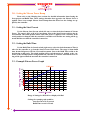
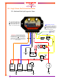
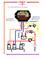
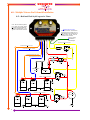
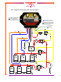
SCHNITZ
Racing
1.800.837.9730
www.schnitzracing.com
Schnitz Motorsports
Performance at its Best!
2-Dial Nitrous
Controller
DCS-101
Installation & and User Guide
1
SCHNITZ
Racing
1.800.837.9730
www.schnitzracing.com
DCS-101, 2-Dial Nitrous Controller
Table of Contents
1.0—Important Information
2.0—Controller Description, Basics of Operation
3.0—Setting the Nitrous Power Ramp
3.1—Setting the Start Percent
3.2—Setting the Build Time
3.3—Example Nitrous Power Graph
4.0—Installation Basics
5.0—Single Nitrous-Fuel Solenoid Installation
5.1—Hold and Wait Style Progressive Timer
5.2—Progressive Timer Reset with Activation Signal
6.0—Multiple Nitrous-Fuel Solenoid Installation
6.1—Hold and Wait Style Progressive Timer
6.2—Progressive Timer Reset with Activation Signal
7.0—Testing Controller Operation and Trouble Shooting
8.0—Specifications
9.0—Warranty
Page 2
Page 3
Page 4
Page 4
Page 4
Page 4
Page 5
Page 6
Page 6
Page 7
Page 8
Page 8
Page 9
Page 10
Page 11
Page 11
1.0—Important Information - Must use Static Suppression Ignition Wires with this
Controller. The DCS-101 Nitrous Controller contains High Frequency Digital Electronics
and will NOT function correctly without Suppression Wires!
Caution - Do NOT submerge Controller in liquid or directly wash unit with liquid of any
type! (Do NOT spray when washing vehicle!)
Warning - The Programming Switches are Delicate Electronic items and can be damaged
by misuse and/or carelessness. If the Controller is close to your NOS Bottle be careful when
installing the bottle. The weight of the bottle is enough to easily damage the switches.
Switches that have been determined to be damaged due to neglect will NOT be covered under Warranty.
It is the responsibility of the purchaser to follow all guidelines and safety procedures
supplied with this product and any other manufactures product used with this product. It is
also the responsibility of the purchaser to determine compatibility of this device with the
vehicle and other components.
Schnitz Motorsports assumes no responsibility for damages resulting from accident,
improper installation, misuse, abuse, improper operation, lack of reasonable care, or all
previously stated reasons due to incompatibility with other manufacturer's products.
Schnitz Motorsports assumes no responsibility or liability for damages incurred
from the use of products manufactured or sold by Schnitz Motorsports on vehicles used for
competition racing. Schnitz Motorsports neither recommends nor approves the use of products manufactured or sold by Schnitz Motorsports on vehicles which may be driven on public highways or roads, and assumes no responsibility for damages incurred from such use.
It is the purchaser’s responsibility to check the state and local laws pertaining to the
use of Nitrous Oxide for racing applications. Schnitz Motorsports does not recommend nor
condone the use of its products for illegal street racing.
2
SCHNITZ
Racing
1.800.837.9730
www.schnitzracing.com
2.0—Controller Description and Basics of Operation
The DCS-101, 2-Dial Nitrous Controller was designed to be a cost effective and accurate controller for the Application of Nitrous Power. By using the latest technology a
.0000025 second resolution timer system is available for precise control of the solenoids. The
programming switches are simple to use and provide binary coded information to the
32Mhz Microcontroller. By using binary coded switches with positive detent positioning the
user selected values will not change with system voltage and/or temperature changes. The
switches are only read during a power on condition and any accidental changes will not be
recognized during operation.
The activation input has been designed to provide a ground while the activation signal is OFF to provide compatibility with Timing Retard Activation Inputs of popular Ignition Systems.
The Starting Percent (initial power) is adjustable from 20% to 50% in 2% increments. When the activation signal is applied, the controller will activate the solenoids using
the selecting starting percent of power. Note, if the build time switch is set to 0.0 the Nitrous
will immediately go to full power regardless of the start percent setting.
The Build Time (Time in seconds to Full Power) is adjustable from 0.0 (Instant Full
Power) to 8.0 seconds in 0.5 second increments. A short build time will apply the nitrous
power much more aggressively than a long build time.
An internal 20 second Timer will begin when the activation signal is applied. After
the 20 second timeout period the controller will wait 2 seconds before resetting the Progressive Timer. The activation signal Must be Removed to complete the Progressive Timer Reset.
The controller can be installed to provide Hold and Wait Timer Function or Reset
Timer with Activation Signal.
The Hold and Wait method will remember where the Nitrous Power was at if the
user lifts the throttle (removes the activation signal) and then Re-Applies it.
The Reset Timer method will Reset the controller every time the activation signal is
removed and re-applied. This method allows the Nitrous Power ramp to be used with each
gear change.
Note - that after the 20 second internal timer has elapsed the Nitrous Solenoids will
be turned OFF. The activation signal must be removed after the 20 second timer has
elapsed or the controller will continue to wait in an OFF condition. When the activation signal is removed all Timers are Reset and the controller is ready for operation again.
Instructions are provided for each method of installation as well as for Single and
Multiple Solenoid installations.
Test Procedures and Trouble Shooting guides have been included. Please see the Table of Contents on Page 2 for further information.
3
SCHNITZ
Racing
1.800.837.9730
www.schnitzracing.com
3.0—Setting the Nitrous Power Ramp
Please refer to the following three sections for detailed information about Setting the
Start percent and Build Time. These settings determine how aggressive the Nitrous Power is
applied. There is an example Nitrous Power Ramp chart that shows how the Settings are applied by the controller.
3.1—Setting the Start Percent
Use the Nitrous Start Percent switch (left one) to select the desired amount of Nitrous
Power. The range is 20% to 50 in 2% increments. Just set the Start Percent switch to the desired amount. The switch position will be read when power is applied to the controller. If the
switch position is changed while the controller is on and/or activated the new setting will be ignored until the next time the controller is turned on.
3.2—Setting the Build Time
Use the Build Time in Seconds switch (right one) to select the desired amount of Time it
takes for the controller to go from the Start Percent to Full Power. The range is 0.0(no build
time, instant full power) to 8.0 in 0.5 second increments. Just set the Build Time switch to the
desired time to full power. The switch position will be read when power is applied to the controller. If the switch position is changed while the controller is on and/or activated the new setting will be ignored until the next time the controller is turned on.
3.3—Example Nitrous Power Graph
PERCENT OF NITROUS
Full Power
100
90
80
70
60
50
40
30
20
Nitrous
Start
Percentage
Build Time in Seconds
0.000 1.000 2.000 3.000 4.000 5.000 6.000 7.000 8.000 9.000
TIME IN SECONDS
Range of Settings for DCS-101 are displayed in Red.
Settings for example graph would be,
Start Percent set at 32 percent
Build Time set at 6.0 seconds
4
SCHNITZ
Racing
1.800.837.9730
www.schnitzracing.com
4.0—Installation Basics
Items Included with the DCS-101 Controller
1 - Wiring Harness
2 - Electrical terminals and shrink wrap
3 - Nitrous Arming Switch
4 - Installation & User Manual
Items needed that are NOT Supplied with Controller
1 - Nitrous Kit
2 - Safety Solenoid
3 - Activation Switches as needed, If not included with the nitrous kit.
4 - 40 Amp Relay, If not included with the nitrous kit.
4 - Static Suppression Ignition Wires
Cautions and Warnings
1 - Always follow Installation Guidelines and Safety Pre-cautions when
installing this and any other related components.
2 - Remove battery Positive when installing new components and/or wiring.
3 - Install Ground Wire first, always connect before battery positive.
4 - Connect Ground wire Direct to Battery Negative Terminal and then
to the Controller.
5 - Always use proper Circuit Protection where required (fuse, circuit breaker).
6 - Do NOT mount the DCS-101 controller in close proximity to Ignition Coils,
Solenoids, or other High voltage-current devices.
6 - Always test system operation after installation to insure proper operation.
7 - Never Weld on vehicle with controller installed!
8 - Turn OFF all electronic devices before connecting, disconnecting a battery
charger.
IMPORTANT - Must use Static Suppression Ignition Wires. Can NOT use any
type of Metal Spiral Core and/or Metal Core Ignition Wires. Controller contains High Frequency Digital Circuitry and can NOT function properly with
RFI or EMI Interference!
5
SCHNITZ
Racing
1.800.837.9730
www.schnitzracing.com
5.0—Single Nitrous-Fuel Solenoid Installation
5.1—Hold and Wait Style Progressive Timer
Note - The Red LED lamp should
be on steady with Arming Switch
ON and the Activation Signal OFF.
LED Lamp will blink when +12V is
applied to the Activation Terminal.
Timing Retard Activation
Note - The activation terminal has an
integrated resistor to Ground. This is to
insure that the Timing Retard Inputs of
popular Ignitions are OFF when the
Controller is NOT activated.
Connect to Timing
Retard Module
Activation Input
Safety Relay Activation, 20GA Yellow
C
NO
NC
Throttle Switch
Launch Switch
and/or
Line Lock
Fuse, 10 Amp 20 GA
Red
Battery
14 GA
Red Nitrous Arming
Switch
DPST
14 GA Red
14 GA Red
20 GA Red
Chassis/Engine
Ground
Fuse, 30 or
40 Amp
+
Ground
20 GA Black
85
86
87A
Solenoid +12V Supply, 14GA Red
30
87
40 Amp Relay
+
Fuel
Solenoid
Nitrous
Solenoid
Safety
Solenoid
Ground
16 GA Black
Nos Fuel Pump
Nitrous Feed Line
To Engine
6
To Nitrous Bottle
Ground
16 GA Black
Activation +12V, 20GA Yellow
+12V Switched, 20 GA Red
Battery Ground, 14GA Black
Nitrous Solenoid Ground, 14GA Blue
Fuel Solenoid Ground, 16GA Orange
IMPORTANT - The Nitrous and Fuel Solenoid
Grounds can be combined on either Output. This
will generally richen the mixture slightly due to the
Fuel Solenoid going to 100% sooner. This happens
because of the large EMF Voltage produced by the
higher amperage Nitrous Solenoid affecting the Fuel
Solenoid Operation.
SCHNITZ
Racing
1.800.837.9730
www.schnitzracing.com
5.2—Progressive Timer Reset with Activation Signal
Timing Retard Activation
Note - The activation terminal has an
integrated resistor to Ground. This is to
insure that the Timing Retard Inputs of
popular Ignitions are OFF when the
Controller is NOT activated.
Note - The Red LED lamp should
be OFF with Arming Switch ON
and the Activation Signal OFF.
LED Lamp will blink when +12V is
applied to the Activation Terminal.
Connect to Timing
Retard Module
Activation Input
C
NO
NC
Throttle Switch
Launch Switch
and/or
Line Lock
Fuse, 10 Amp 20 GA
Red
Battery
14 GA
Red Nitrous Arming
Switch
DPST
14 GA Red
14 GA Red
20 GA Red
Chassis/Engine
Ground
Fuse, 30 or
40 Amp
+
Ground
20 GA Black
85
86
87A
Solenoid +12V Supply, 14GA Red
30
87
40 Amp Relay
+
Fuel
Solenoid
Nitrous
Solenoid
Safety
Solenoid
Ground
16 GA Black
Nos Fuel Pump
Nitrous Feed Line
To Engine
7
To Nitrous Bottle
Ground
16 GA Black
Activation +12V, 20GA Yellow
+12V Switched, 20 GA Red
Battery Ground, 14GA Black
Nitrous Solenoid Ground, 14GA Blue
Fuel Solenoid Ground, 16GA Orange
Safety Relay Activation, 20GA Yellow
SCHNITZ
Racing
1.800.837.9730
www.schnitzracing.com
6.0—Multiple Nitrous-Fuel Solenoid Installation
6.1—Hold and Wait Style Progressive Timer
Note - The Red LED lamp should
be on steady with Arming Switch
ON and the Activation Signal OFF.
LED Lamp will blink when +12V is
applied to the Activation Terminal.
Timing Retard Activation
Note - The activation terminal has an
integrated resistor to Ground. This is to
insure that the Timing Retard Inputs of
popular Ignitions are OFF when the
Controller is NOT activated.
Connect to Timing
Retard Module
Activation Input
Nitrous Solenoid Ground, 14GA Blue
Fuel Solenoid Ground, 16GA Orange
NO
NC
Throttle Switch
Launch Switch
and/or
Line Lock
Fuse, 10 Amp 20 GA
Red
Nitrous Solenoid Ground, 14GA Blue
Battery
Fuse, 30 or
40 Amp
14 GA
Red Nitrous Arming
Switch
DPST
14 GA Red
14 GA Red
20 GA Red
Chassis/Engine
Ground
C
Activation +12V, 20GA Yellow
+12V Switched, 20 GA Red
Battery Ground, 14GA Black
Fuel Solenoid Ground, 16GA Orange
Safety Relay Activation, 20GA Yellow
+
85
86
87A
30
Solenoid +12V Supply, 14GA Red
Ground
20 GA Black
87
40 Amp Relay
Fuel
Solenoid
Nitrous
Solenoid
Safety
Solenoid
Ground
16 GA Black
Nitrous Feed Line
To
Nitrous
Bottle
To Engine
+
Solenoid +12V Supply, 14GA Red
85
86
87A
Fuel
Solenoid
Nitrous
Solenoid
Safety
Solenoid
Ground
16 GA Black
Nos Fuel Pump
30
Ground
20 GA Black
-
87
40 Amp Relay
Nitrous Feed Line
To Engine
8
To Nitrous Bottle
Ground
16 GA Black
SCHNITZ
Racing
1.800.837.9730
www.schnitzracing.com
6.2—Progressive Timer Reset with Activation Signal
Note - The Red LED lamp should
be OFF with Arming Switch ON
and the Activation Signal OFF.
LED Lamp will blink when +12V is
applied to the Activation Terminal.
Timing Retard Activation
Note - The activation terminal has an
integrated resistor to Ground. This is to
insure that the Timing Retard Inputs of
popular Ignitions are OFF when the
Controller is NOT activated.
Connect to Timing
Retard Module
Activation Input
Nitrous Solenoid Ground, 14GA Blue
Fuel Solenoid Ground, 16GA Orange
NO
NC
Throttle Switch
Launch Switch
and/or
Line Lock
Fuse, 10 Amp 20 GA
Red
Nitrous Solenoid Ground, 14GA Blue
Battery
Fuse, 30 or
40 Amp
14 GA
Red Nitrous Arming
Switch
DPST
14 GA Red
20 GA Red
14 GA Red
Chassis/Engine
Ground
C
Activation +12V, 20GA Yellow
+12V Switched, 20 GA Red
Battery Ground, 14GA Black
Fuel Solenoid Ground, 16GA Orange
Safety Relay Activation, 20GA Yellow
+
85
86
87A
30
Solenoid +12V Supply, 14GA Red
Ground
20 GA Black
87
40 Amp Relay
Fuel
Solenoid
Nitrous
Solenoid
Safety
Solenoid
Ground
16 GA Black
Nitrous Feed Line
To
Nitrous
Bottle
To Engine
+
Solenoid +12V Supply, 14GA Red
85
87A
Fuel
Solenoid
Nitrous
Solenoid
Safety
Solenoid
Ground
16 GA Black
Nos Fuel Pump
86
30
Ground
20 GA Black
-
87
40 Amp Relay
Nitrous Feed Line
To Engine
9
To Nitrous Bottle
Ground
16 GA Black
SCHNITZ
Racing
1.800.837.9730
www.schnitzracing.com
7.0—Testing Controller Operation and Trouble Shooting
The controller operation can be tested with the vehicle engine OFF, Nitrous Fuel
Supply OFF, and the Nitrous Supply (bottle) OFF. Never test the system with Fuel and
Nitrous Supply ON, this will fill the non-running engine and can be very destructive to
engine components and personnel when it is started the next time!
After insuring that all supplies are OFF, turn On the Nitrous Arming Switch.
Depress the Throttle (or activate throttle switch manually) to activate the controller. If
the controller is set for 0.0 build time the solenoids should snap open immediately. Any
other setting will pulsate the solenoids for the build time setting and then the solenoids
will go to full power.
The Red LED Lamp will be on solid with the controller On and NOT activated.
When the activation signal is applied the LED Lamp will blink. This can be used to
check for proper activation signal.
If the controller has been installed for Hold and Wait Timer releasing the throttle switch will stop the solenoids. When the throttle switch is applied again the controller will resume at the point it was stopped at (provided the internal 20 second has not
elapsed). If the internal 20 second timer has elapsed before the throttle is released the
solenoids will be turned OFF until the activation signal is released and reapplied.
If the controller has been installed for Reset with Activation Signal releasing the
throttle switch will turn off the controller and the solenoids. When the throttle switch is
applied again the controller will begin the Nitrous Power Ramp from the start percent
setting. If the internal 20 second timer has elapsed before the throttle is released the
solenoids will be turned OFF until the activation signal is released and reapplied.
Trouble Shooting Incorrect Controller Operation.
1 - Engine Running Rich while using Progressive Nitrous
A - Starting Percentage to low for a given bottle pressure and solenoid
combination (only fuel solenoid opening).
B - Fuel pressure to high for fuel solenoid to operate correctly when pulsating.
2 - Nitrous seems to Delay after Activation
A - Improper Nitrous Jetting, Fuel Jet to rich. Some vehicles will run rich
with the Nitrous Controller installed due to the Fuel being slightly richer
at low percentages.
B - Starting Percentage to low for a given bottle pressure and solenoid
combination (only fuel solenoid opening).
3 - Nitrous Turns OFF during operation
A - To much current draw from solenoids. System fuse-circuit breaker may be
overloaded. Controller will limit amperage to the solenoids if an over current
condition is detected. See specifications for maximum ratings.
B - Electrical interference from Ignition System or other Electronic Device(s)
causing the controller to lock up or turn off.
10
SCHNITZ
Racing
1.800.837.9730
www.schnitzracing.com
8.0—Specifications
Normal Operating Voltage 10.0 to 16.0 Volts, Negative Ground
Controller will Turn OFF at 6.2 Volts
Solenoid Outputs
45 Amps Maximum each output
Activation Input
125mA at 12.0 Volts
Weight (approx)
Overall Height
Overall Width
Overall Length
.4 lb.
1.750 in.
3.125 in.
4.375 In.
9.0—Warranty
Schnitz Motorsports warrants to the original purchaser that the components
shall be free from defects in parts and workmanship under normal use for 6 months
from the date of purchase.
Schnitz Motorsports obligation under this warranty is limited to the repair or
replacement of any component found to be defective when returned postpaid to Schnitz
Motorsports. The item must be returned with evidence of place and date of purchase or
warranty will be void. The warranty will not apply to any component that has been
used incorrectly, repaired, damaged, or tampered with by misuse, negligence or accident.
11