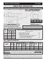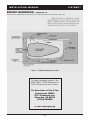
1
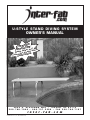
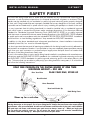
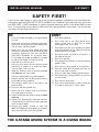
U - S T Y L E S TA N D D I V I N G S Y S T E M
Assembly & Installation Instructions
TION :
N
E
T
AT
LERS
L
d
A
T
INS deliver an with
l
e
Pleas his manua .
R
t
E
w
revie OMEOWN
H
3050 S. ALVERNON WAY • TUCSON, AZ 85713
520.790.7040 • 800.737.5386 • FAX 520.790.7127
i n t e r - f a b . c o m
U-STAND-IM Rev. 3/09 (BK-USTAND BOOK)
U - S T Y L E S TA N D D I V I N G S Y S T E M
OWNER’S MANUAL
TION :
N
E
T
AT
LERS
L
d
A
T
INS deliver an with
l
e
Pleas his manua .
R
t
E
w
revie OMEOWN
H
3050 S. ALVERNON WAY • TUCSON, AZ 85713
520.790.7040 • 800.737.5386 • FAX 520.790.7127
i n t e r - f a b . c o m
U-STAND-IM Rev. 3/09 (BK-USTAND BOOK)
For Technical Support or Assistance,
Contact Customer Service at:
INTER-FAB, INC.
3050 S. ALVERNON WAY
TUCSON, AZ 85713
(800) 737-5386
or visit: www.inter-fab.com
To obtain complete copies of the most current
ANSI/NSPI 2003 Standards for Inground Pools or
to obtain copies of the “Plan Your Dive, Steer Up”
or “The Sensible Way to Enjoy Your Inground
Swimming Pool” contact:
The Association of Pool & Spa Professionals
(APSP)
2111 Eisenhower Ave.
Alexandria, VA 22314
(703) 838-0083
or visit: www.theapsp.org
U-STAND-IM Rev. 3/09 (BK-USTAND BOOK)
INSTALLATION MANUAL
U-STAND™
TABLE OF CONTENTS:
Safety First .........................................................................2-3
Important Notices to the Installer..............................................4
Board to Base Compatibility Chart.............................................4
RESIDENTIAL:
Minimum Diving Water Envelope Information...............................5
U-Stand Base Placement - Residential........................................6
U-Stand Specifications - Residential ...........................................6
Exploded View Diagram............................................................7
Installation Instructions - Residential ..........................................8
Article 5 Extracted from ANSI/NSPI-5 2003 .........................9-14
COMMERCIAL:
U-Stand Base Placement - Commercial ....................................15
U-Stand Specifications - Commercial ........................................15
Public Board Mounting Diagram..............................................16
Installation Instructions - Commercial.......................................16
Article 5 Extracted from ANSI/NSPI-1 2003 .......................17-25
Inter-Fab Limited Warranty.....................................................26
U-STAND-IM Rev. 3/09 (BK-USTAND BOOK)
1
INSTALLATION MANUAL
U-STAND™
SAFETY FIRST!
This Inter-Fab diving board and/or stand shall be installed only by a professional swimming pool
contractor or with the direct supervision of a licensed professional, engineer or architect. Diving
boards may be installed only on residential or public inground swimming pools properly designed
for their use. Diving boards that are improperly installed can be very dangerous to the user resulting
in possible serious head and/or spinal column injury, including the paralysis or death of the user.
It is very important that this diving board and/or stand be installed only on residential inground
pools which meet or exceed the minimum water envelope dimensions of the American National
Standard for Residential Inground Swimming Pools [ANSI/NSPI-5 2003) or on public inground
pools that meet or exceed the minimum water envelop dimensions of the ANSI/NSPI-1 2003 standard
for public pools and in accordance with the included INTER-FAB POOL SPECIFICATIONS. Installation
should conform to local building regulations if they exceed the ANSI/NSPI standards.
In addition to the above standards and referenced specifications, these installation instructions
provided by Inter-Fab, Inc. must be followed diligently.
It is also important that any and all warnings provided with the diving board be strictly adhered to
and posted in a conspicuous location. If not provided or they are misplaced, please purchase warning
signs from your pool contractor or professional pool supply store and post them in a location that
the users of the diving board can clearly see.
“A pool is the safest place to swim and a diving board installed in compliance with manufacturers
instructions and the ANSI/NSPI-5 2003 standards for residential inground swimming pools and
the ANSI/NSPI-1 2003 standards for public inground swimming pools is the safest place to dive
from. To ensure that you are able to safely enjoy your diving board for many years, it is critical that
you follow the following instructions.”
ONLY ONE PERSON ON THE DIVING BOARD AT ONE TIME
MAXIMUM WEIGHT = 250 LBS
PLAN YOUR DIVE, STEER UP
Plan Your Dive
Back Arched
Arms Extended
Head and Hands Up
Hold Diving Form
Steer up for a safe dive.
DIVING TIPS: Even the safest equipment must be used properly. Inter-Fab promotes safe diving by
offering these tips on the proper use of your diving board: always dive into water that meets depth
requirements, with arms extended; be aware of the bottom and the walls of the pool; avoid collisions
with pool toys and floats; and instruct your pool users to always “steer up”. When you begin your
dive you must get ready to steer up. As you enter the water, your arms must be extended over
your head, hands flat aiming up. Hold your head and arch your back.
U-STAND-IM Rev. 3/09 (BK-USTAND BOOK)
2
INSTALLATION MANUAL
U-STAND™
SAFETY FIRST!
A pool is the safest place to swim and a diving board installed in compliance with manufacturers
instructions and the ANSI/NSPI-5 2003 standards for residential inground swimming pools and
the ANSI/NSPI-1 2003 standards for public inground swimming pools is the safest place to dive
from. To ensure that you are able to safely enjoy your diving board for many years, it is critical that
you follow the following instructions.
DO
DON’T
1.
Know the shape and depth of the pool before
you dive.
1.
Don’t drink and dive.
2.
2.
Make sure that all family members and guests
are familiar with these instructions before they
use your pool and diving board.
Don’t install this or any diving board on an
above ground pool or dive into an above
ground pool from any surface.
3.
3.
Make sure that the diving board has been
installed in compliance with the Assembly and
Installation Instructions and with the 2003
ANSI/NSPI Standards for In-ground Pools.
This includes the shape and depth of the pool
as well as the height of the diving board.
Don’t dive into a pool from anyplace not specifically designated for diving. Never dive into the
shallow portion of any pool.
4.
Don’t dive across the width of the pool or to
the sides of the pool.
5.
Don’t Run and dive.
4.
Enter feet first the first time.
6.
5.
Plan your path to be sure you avoid any other
swimmers, or objects in or under the water,
such as floats, tires, toys etc.
Don’t engage in horseplay in or around the diving
board or pool.
7.
Don’t use your diving board as a trampoline.
8.
Keep your head up, arms up and fully extended
and steer up with your hands.
Don’t do a back dive. Backyard pools are not
built for that type of activity.
9.
Don’t try fancy dives. Keep the dives simple.
7.
Practice carefully before you dive headfirst.
8.
Become familiar with the diving board and its
spring before diving headfirst
10. Don’t dive into or through objects or toys such
as inner tubes.
6.
9.
11. Don’t swim or dive alone.
12. Don’t use a diving board or stand or base that
is rusted or worn out or in poor repair.
Dive straight ahead, not to the side of the
board or pool.
10. Dive from the diving board only.
11. Make sure that children and non-swimmers
are supervised at all times.
12. Always remember that when you dive you must
steer up.
13. Inspect your diving board, base and stand on
a regular basis (at least twice a year) and keep
them in proper repair.
14. Contact your dealer, installer or Inter Fab
(800-737-5386) with any questions or concerns
about the safe use of your diving board.
THE U-STAND DIVING SYSTEM IS A DIVING BOARD
U-STAND-IM Rev. 3/09 (BK-USTAND BOOK)
3
INSTALLATION MANUAL
U-STAND™
IMPORTANT NOTICES
TO THE INSTALLER
The specifications found in this manual represent the minimum water envelope required by Inter-fab
and by the ANSI/NSPI 2003 Standards for Inground Swimming Pools. Each of these dimensions
must be met or exceeded. Installation of a diving board of any type on a pool that does not meet
or exceed each of the minimum specifications as provided in this manual including but not limited
to the slope requirement, is in direct violation of this manufacturer’s instructions and the 2003
Standards, and can result in serious injury or death.
A 6’ diving board can only be installed on a 12” or 18” U-Stand base; an 8’ diving board can only
be installed on a 12” or 18” U-Stand base; a 10’ diving board can only be installed on an 18” or
24” U-Stand base; and a 12’ diving board can only be installed on a 24” U-Stand base.
Comply with local government regulations for Inground Swimming Pools if they exceed the
ANSI/NSPI 2003 Standards.
Read carefully pages 9-14 and pages 17-25 of this installation manual which contain portions of
the ANSI/NSPI-5 2003 Standard for Residential Inground Swimming Pools, and the ANSI/NSPI-1
2003 Standard for Public Swimming Pools.
NOTE: The installation of this diving board and/or stand is not complete until you, the installer
have measured the pool as well as the diving board’s height above water and the board’s overhang
to ensure they meet Inter-Fab’s minimum water envelope specifications and the ANSI/NSPI 2003
Standards For Inground Swimming Pools. In addition, the installation of this diving board and/or
stand is not complete until you the installer have delivered to your customer and reviewed with your
customer the “Owners Manual” as well as the “Plan Your Dive Steer-Up” brochure.
ONLY ONE PERSON AT A TIME ON THE DIVING BOARD,
WITH A MAXIMUM WEIGHT LIMIT OF 250 LBS.
INTER-FAB BOARD TO BASE COMPATIBILITY CHART **
DURO-BEAM
DURO-SPRING
TECHNI-BEAM
BAJA
OLYMPIAN
COMMERCIAL
BASE TYPE
6’
8’
10’
6’
8’
6’
8’
10’
12’
6’
8’
6’
8’
10’
10’
12’
14’
16’
U-Stand 12”
U-Stand 18”
U-Stand 24”
S
S
–
S
S
–
–
S
S
–
–
–
–
–
–
U1
U1
–
U1
U1
–
–
U1
U1
–
–
U1
–
–
–
–
–
–
U2
U2
–
U2
U2
–
–
U2
U2
–
U3
U3
–
–
U3
–
–
–
–
–
–
CHART KEY:
S = STANDARD; U1 = UPGRADE 1; U2 = UPGRADE 2; U3 = UPGRADE 3;
– = NOT AVAILABLE
** NOTE: The Chart above refers to standard wood core diving boards and standard fiberglass and steel diving bases.
U-STAND-IM Rev. 3/09 (BK-USTAND BOOK)
4
INSTALLATION MANUAL
U-STAND™
RESIDENTIAL INGROUND POOL INSTALLATION
MINIMUM DIVING WATER ENVELOPE:
NOTE: DRAWINGS ARE NOT TO SCALE.
F
G
H
DIVING EQUIPMENT
J
TIP OF BOARD
ABOVE POINT A
N
M
DIVING EQUIPMENT
L
TABLE 1 - MINIMUM WATER ENVELOPE (ANSI/NSPI-5 2003)
POOL
TYPE
MINIMUM DEPTHS
AT POINT
A
B
C
MINIMUM WIDTHS
AT POINT
D
A
DIVING
0
B
C
MINIMUM LENGTHS
BETWEEN POINTS
D
WA+/-3”
EQUIPMENT
AB
BC
CD*
DE
WE
PROHIBITED
I
6’-0”
7’-6”
5’-0”
2’-9” 10’-0” 12’-0” 10’-0” 8’-0”
1’-6”
7’-0”
7’-6” VARIES 6’-0”
28’-9”
II
6’-0”
7’-6”
5’-0”
2’-9” 12’-0” 15’-0” 12’-0” 8’-0”
1’-6”
7’-0”
7’-6” VARIES 6’-0”
28’-9”
III
6’-10” 8’-0”
5’-0”
2’-9” 12’-0” 15’-0” 12’-0” 8’-0”
2’-0”
7’-6”
9’-0” VARIES 6’-0”
31’-3”
IV
7’-8”
8’-6”
5’-0”
2’-9” 15’-0” 18’-0” 15’-0” 9’-0”
2’-6”
8’-0” 10’-6” VARIES 6’-0”
33’-9”
V
8’-6”
9’-0”
5’-0”
2’-9” 15’-0” 18’-0” 15’-0” 9’-0”
3’-0”
9’-0” 12’-0” VARIES 6’-0”
36’-9”
TABLE 2 - INTER-FAB RESIDENTIAL POOL MINIMUM SPECIFICATIONS
POOL
TYPE
MAX. DIVING
BOARD
LENGTH
DBL**
MAX. HEIGHT
OVER WATER
AT POINT A
HOW**
CROSS SECTIONAL
DIMENSIONS AT
POINT A
F
DIVING
0
G
CROSS SECTIONAL DIMENSIONS AT POINT B
H
J
EQUIPMENT
K
L
M
N
MIN. HEAD
ROOM
ABOVE
DIVING
SURFACES
PROHIBITED
I
6’ DB/6’ JB
20”
2’-9”
5’-0”
4’-0”
7’-2.5”
7’-6”
6’-0”
3’-9”
2’-1.5”
12’
II
8’ DB/6’ JB
20”
2’-9”
3’-10”
4’-2”
7’-2.5”
7’-6”
6’-8”
3’-9”
2’-1.5”
12’
III
10’ DB/8’ JB
26”
2’-9”
4’-4.75”
4’-4.5”
7’-5.5”
8’-0”
6’-7”
IV
10’ DB/8’ JB
30”
2’-9”
5’-10.5”
3’-10”
7’-8”
8’-6”
8’-3”
5’-7”
2’-7”
13’
V
12’ DB/8’ JB
40”
2’-9”
6’-2”
9’-0”
8’-2.5”
5’-9”
2’-7”
14’
3’-11.5” 7’-9.5”
*Min. length between points CD may vary based upon water depth at point D and the slope between points C & D
ABBREVIATIONS: **DBL=Diving Board Length; DB=Diving Board; JB=Jump Board; **HOW=Height Over Water
U-STAND-IM Rev. 3/09 (BK-USTAND BOOK)
5
3’-11.5” 1’-7.5”
13’
NOTES:
K
INSTALLATION MANUAL
U-STAND™
RESIDENTIAL INGROUND POOL INSTALLATION
NOTE: READ THESE INSTRUCTIONS IN THEIR ENTIRETY BEFORE ATTEMPTING THE INSTALLATION.
FIG. A – U-STAND RESIDENTIAL
PLACEMENT SPECIFICATIONS:
WA
INTER-FAB CANNOT GUARANTEE CUSTOMER’S
CONCRETE OR THICKNESS
NOTE: WHEN COPING IS USED, DO NOT SET FRONT U-STAND
CLOSER THAN 3” FROM THE BACK EDGE OF THE COPING.
TABLE 5 – RESIDENTIAL PLACEMENT CHART
TABLE 3 – U-STAND SPECS
TABLE 4 – U-STAND MATERIAL
A
B
C
MODEL
6’
12”, 18”
30” ±3”
DBU12049
SIZE
12”
OD
1.90”
WALL
.049”
8’
12”, 18”
40” ±4”
DBU18049
18”
1.90”
.049”
10’
18”, 20”
52” ±5”
DBU18065
18”
1.90”
.065”
12’
20”
62” ±6”
DBU24065
20”
1.90”
.065”
IMPORTANT NOTICE: WHEN PROPERLY INSTALLED, INTER-FAB’S 12” AND 18”
U-STANDS WILL HAVE 4” OF THE RAIL EMBEDDED WITHIN THE DECK AND WILL
MEASURE (RESPECTIVELY) 12” OR 18” FROM THE TOP OF THE RAIL TO THE SURFACE
OF THE DECK. THE 24” U-STAND IS DIFFERENT, WHEN PROPERLY INSTALLED 4” OF
THE RAIL WILL BE EMBEDDED WITHIN THE DECK AND IT WILL MEASURE 20” FROM
THE TOP OF THE RAIL TO THE SURFACE OF THE DECK.
ADDITIONALLY REFER TO: ANSI/NSPI-5 2003 American National Standard for Residential Inground
Swimming Pools and to page 5 for Inter-Fab Residential Inground Pool Minimum Specifications.
IMPORTANT:
U-STANDARDS
PART #
THESE DIMENSIONS
(Note: there are several sizes
available for each pool type)
ARE ACCURATE ONLY
FOR VERTICAL POOL
WALLS, TYPICALLY
GUNITE CONSTRUCTION,
WITH
LESS
THAN A 3’ RADIUS TO
THE POOL FLOOR.
DUE TO THE VARYING
SIZES
POOLS,
OF
OTHER
DBU12049
DBU12049
DBU12049 or DBU18049
DBU12049 or DBU18049
DBU12049 or DBU18049
DBU12049
DBU12049 or DBU18049
DBU12049 or DBU18049
DBU12049 or DBU18049
TYPICALLY
VINYL LINER CONSTRUCTION, PLEASE
CONTACT CUSTOMER
DBU18049 or DBU24049
DBU18049 or DBU24049
DBU18049 or DBU24049
SERVICE FOR PROPER
PLACEMENT.
1-800-737-5386
DBU24
NOMINAL
BOARD
LENGTH
ANSI/
NSPI-5
POOL
TYPE
6’
6’
6’
6’
6’
8’
8’
8’
8’
8’
10’
10’
10’
10’
10’
12’
12’
12’
12’
12’
I
II
III
IV
V
I
II
III
IV
V
I
II
III
IV
V
I
II
III
IV
V
DISTANCE FROM
WATER’S EDGE
TO FORWARD
U-STAND
(S)
DISTANCE
FROM END
OF BOARD
TO FORWARD
U-STAND
MIN.
OVERHANG
PLUS OR
MINUS 3”
(WA)
MAX HEIGHT
OF BOARD
ABOVE
WATER
(HOW)
18.25”
18.25”
12.25”
6.25”
36.25”
36.25”
36.25”
36.25”
18”
18”
24”
30”
20”
20”
26”
30”
Not recommended. Call customer service for more information.
NOT ALLOWED
32”
26”
20”
14”
50”
50”
50”
50”
18”
24”
30”
36”
20”
26”
30”
40”
24”
30”
36”
26”
30”
40”
36”
40”
NOT ALLOWED
NOT ALLOWED
37.5”
31.5”
25.5”
61.5”
61.5”
61.5”
NOT ALLOWED
NOT ALLOWED
NOT ALLOWED
NOT ALLOWED
40”
76”
* IMPORTANT: The distance for setting the front jig bolt (S) from the water’s edge is valid only if the minimum water depth is maintained at the tip of the board noted as
point “A” in ANSI/NSPI-5 2003 American National Standard for Residential Inground Swimming Pools. If minimum water depth is not maintained the distance (S) must
be adjusted accordingly.
** “WA” dimension is valid only in conjunction with the minimum depth at point “A” for type pool in accordance with ANSI/NSPI-5 2003 American National Standard
for Residential Inground Swimming Pools.
U-STAND-IM Rev. 3/09 (BK-USTAND BOOK)
6
INSTALLATION MANUAL
U-STAND™
RESIDENTIAL INGROUND POOL INSTALLATION
FIG. B – U-STAND BASE EXPLODED VIEW
NO. 3 Rebar
(Not Included)
DRAWING REPRESENTS THE FOLLOWING PART NUMBERS:
DBU12049 (shown)
DBU18049
DBU18065
DBU24049
DBU24065
COMPONENT
DESCRIPTION
1
2
3
4
5
6
7
8
9
10
11
DBU12049
DB6WW
FC
H-WHT WAS/CAP
H-SS 5 C BOLT
H-1/2 BLK WASH
H-1/2 RED WASH
H-SS 1/2 F WAS
H-SS 1/2 LOC WA
H-SS 1/2 H NUT
H-1-1/2 WHT CAP
12" U Style Diving Standards
6' Duro-Beam White w/White Top Tread & Hdw Kit
Fulcrum Cover For U-Standard Base
I.F. White Washer/Cap
1/2-13 x 5 Carriage Bolt S.S.
1/2 x 2" Black Rubber Washer
1/2 x 2" Red Rubber Washer
1/2 USS Flat Washer S.S.
1/2 Lock Washer S.S.
1/2"- 13 Hex Finish Nut S.S.
.750 x 1-1/2 White UV Nut Cap
TIGHTENING SCHEDULE:
Secure Board to Stand with
Mounting Hex Nuts at 20-25
FT-LBS
N/A
ITEM #
KITS – QTY.
DB-M
TABLE 6 – PARTS LIST
2
1
1
2
2
2
2
2
2
2
2
HARDWARE NOTE:
Use a small dab of anti seize
lubricant (included) on all bolt
threads.
NOTES:
DB6WW diving board shown in exploded view for illustration purposes. Must be purchased separately. Other diving board options available.
U-STAND-IM Rev. 3/09 (BK-USTAND BOOK)
7
INSTALLATION MANUAL
U-STAND™
RESIDENTIAL INGROUND POOL INSTALLATION
U-Stand Diving Base
RESIDENTIAL POOL INSTALLATION INSTRUCTIONS
Be sure the concrete deck surrounding the U-Stands complies with the minimum dimensions as
shown in Figure A on page 6.
Read and understand the ANSI/NSPI-5 2003 American National Standard for Residential Inground
swimming Pools and Table 1 and Table 2 on page 5 before you install the U-Stand Diving System.
The U-Stands should be set in accordance with Figure A and Table 3 on page 6. The diving board
must be placed on the deep end of the pool on centerline.
Make sure the U-Stands are set 4” into the concrete with ample concrete depth below the stand in
accordance with Figure A on page 6. Do not install the U-Stand Diving System if the deck does not
meet the minimum requirements.
When finishing the deck surface, maintain a level deck where the U-Stands project out of the deck
surface. Both U-Stands must be leveled left to right and to each other when installing. This will allow
the diving board to sit level left to right and have a slight upward pitch at the toe end once the rubber
fulcrum pad is in place. Allow the cement to fully cure before bolting the diving board to the U-Stands.
When mounting diving board to a newly installed stand with a permanently fixed fulcrum, the correct
measurement between the mounting holes and the fulcrum must be maintained so as not to void
the warranty. See Figure A and Table 3 on page 6.
The rubber fulcrum pad MUST be used so as not to void the Inter-Fab warranty.
The Diving Board must be installed according the below board leveling instructions:
The top surface of the diving board from the deck end to
the tip end shall be level or have an upward slope of 5/8"
per foot maximum. Elevation difference shall not exceed
6" from the deck end to the tip of the board. There shall
be no downward slope towards the water. The slope shall
be measured using a level as shown in the graphic to the
left.
ONLY ONE PERSON ON THE DIVING BOARD AT A TIME, WITH A MAXIMUM WEIGHT
OF 250 LBS.
U-STAND-IM Rev. 3/09 (BK-USTAND BOOK)
8
INSTALLATION MANUAL
U-STAND™
SUPPORT INFORMATION:
ARTICLE 5 – POOL DIMENSIONS AND TOLERANCES
Extracted from ANSI/NSPI- 2003, American National Standard for Residential Inground Swimming Pools
U-STAND-IM Rev. 3/09 (BK-USTAND BOOK)
9
INSTALLATION MANUAL
U-STAND™
SUPPORT INFORMATION:
ARTICLE 5 – POOL DIMENSIONS AND TOLERANCES
Extracted from ANSI/NSPI- 2003, American National Standard for Residential Inground Swimming Pools
U-STAND-IM Rev. 3/09 (BK-USTAND BOOK)
10
INSTALLATION MANUAL
U-STAND™
SUPPORT INFORMATION:
ARTICLE 5 – POOL DIMENSIONS AND TOLERANCES
Extracted from ANSI/NSPI- 2003, American National Standard for Residential Inground Swimming Pools
U-STAND-IM Rev. 3/09 (BK-USTAND BOOK)
11
INSTALLATION MANUAL
U-STAND™
SUPPORT INFORMATION:
ARTICLE 5 – POOL DIMENSIONS AND TOLERANCES
Extracted from ANSI/NSPI- 2003, American National Standard for Residential Inground Swimming Pools
U-STAND-IM Rev. 3/09 (BK-USTAND BOOK)
12
INSTALLATION MANUAL
U-STAND™
SUPPORT INFORMATION:
ARTICLE 5 – POOL DIMENSIONS AND TOLERANCES
Extracted from ANSI/NSPI- 2003, American National Standard for Residential Inground Swimming Pools
U-STAND-IM Rev. 3/09 (BK-USTAND BOOK)
13
INSTALLATION MANUAL
U-STAND™
SUPPORT INFORMATION:
ARTICLE 5 – POOL DIMENSIONS AND TOLERANCES
Extracted from ANSI/NSPI- 2003, American National Standard for Residential Inground Swimming Pools
To obtain complete copies of the ANSI/NSPI-5 2003 Standard
for Residential Inground Pools contact:
The Association of Pool & Spa Professionals (APSP)
2111 Eisenhower Ave.
Alexandria, VA 22314
(703) 838-0083
or visit: www.theapsp.org
U-STAND-IM Rev. 3/09 (BK-USTAND BOOK)
14
INSTALLATION MANUAL
U-STAND™
PUBLIC POOL INSTALLATION
NOTE: READ THESE INSTRUCTIONS IN THEIR ENTIRETY BEFORE ATTEMPTING THE INSTALLATION.
FIG. C – U-STAND COMMERCIAL
PLACEMENT SPECIFICATIONS:
TABLE 7 – U-STAND MATERIAL
TABLE 8 – INTER-FAB PUBLIC POOL SPECIFICATIONS
RELATED DIVING EQUIPMENT
POOL
TYPE
MAX. DIVING MAX. BOARD
BOARD
HEIGHT
LENGTH
OVER WATER
VI
10’
VII
12’
VIII
16’
(2/3 Meter)
26”
(3/4 Meter)
30”
1 Meter
IX
16’
3 Meter
SIZE
OD
WALL
18”
1.90”
.065”
DBU24065
24”
1.90”
.065”
MATERIALS: 1.90” OD, .065” WALL, 304
STAINLESS STEEL.
NOTE: ONLY .065” U-STANDS CAN BE
INSTALLED ON A PUBLIC POOL.
INTER-FAB CANNOT GUARANTEE CUSTOMER’S
CONCRETE OR THICKNESS
NOTE: WHEN COPING IS USED, DO NOT SET FRONT U-STAND
CLOSER THAN 3” FROM THE BACK EDGE OF THE COPING.
MODEL
DBU18065
IMPORTANT NOTICE: WHEN PROPERLY INSTALLED, INTER-FAB’S 18” U-STAND WILL
HAVE 4” OF THE RAIL EMBEDDED WITHIN THE DECK AND WILL MEASURE 18” FROM
THE TOP OF THE RAIL TO THE SURFACE OF THE DECK. THE 24” U-STAND IS DIFFERENT,
WHEN PROPERLY INSTALLED 4” OF THE RAIL WILL BE EMBEDDED WITHIN THE DECK
AND IT WILL MEASURE 20” FROM THE TOP OF THE RAIL TO THE SURFACE OF THE DECK.
Placement of boards shall observe the following minimum dimensions.
With multiple board installations, minimum pool widths must be
increased accordingly.
•
•
•
•
•
Deck Level Board to Pool Side
1 Meter Board to Pool Side
3 Meter Board to Pool Side
1 Meter or Deck Level Board to 3 Meter Board
1 Meter or Deck Level Board to Another
1 Meter or Deck Level Board
• 3 Meter to Another 3 Meter Board
8’
10’
11’
10’
8’
10’
TABLE 9 – COMMERCIAL PLACEMENT CHART
ADDITIONALLY REFER TO: ANSI/NSPI-1 2003 American National Standard for Public Swimming Pools.
U-STANDARDS
PART #
NOMINAL
BOARD
LENGTH
(A)
ANSI/
NSPI-5
POOL
TYPE
DISTANCE FROM
WATER’S EDGE
TO FORWARD
U-STAND
(S)
DISTANCE
FROM END
OF BOARD
TO FORWARD
U-STAND
MIN.
OVERHANG
(L1)
MAX HEIGHT
OF BOARD
ABOVE
WATER
(HOW)
HEIGHT OF
U-STAND
(B)
FULCRUM
SETTING
(C)
DBU18065 or DBU24065
DBU18065 or DBU24065
DBU24065
10’
10’
12’
VI
VII
VII
31.5”
25.5”
40”
61.5”
61.5”
76”
30”
36”
36”
26”
30”
30”
18”, 20”
18”, 20”
20”
52” ± 5”
52” ± 5”
62” ± 6”
IMPORTANT:
THESE DIMENSIONS ARE ACCURATE ONLY FOR VERTICAL POOL WALLS, TYPICALLY GUNITE
CONSTRUCTION. PLEASE CONTACT CUSTOMER SERVICE FOR PROPER PLACEMENT.
1-800-737-5386
* IMPORTANT: The distance for setting the front jig bolt (S) from the water’s edge is valid only if the minimum water depth is maintained at the tip of the board noted as
point “A” in ANSI/NSPI-1 2003 American National Standard for Public Inground Swimming Pools. If minimum water depth is not maintained the distance (S) must be
adjusted accordingly.
** L1 dimension is valid only in conjunction with the minimum depth at point “A” for type pool in accordance with ANSI/NSPI-1 2003 American National Standard for
Public Inground Swimming Pools.
U-STAND-IM Rev. 3/09 (BK-USTAND BOOK)
15
INSTALLATION MANUAL
U-STAND™
PUBLIC POOL INSTALLATION
FIG. D – PUBLIC POOL BOARD MOUNTING DIAGRAM
Mounting Kit
Diving Board
1
2
HARDWARE NOTE:
Use a small dab of
anti seize lubricant
(included) on all bolt
threads.
3
3
U-Stand
4
5
6
7
NOTE: Tighten Hex Nuts
Between 20-25 FT/LBS.
DO NOT OVER TIGHTEN.
COMMERCIAL MOUNTING KIT KEY:
1. 1/2” X 6” Carriage Bolt Stainless Steel (2 ea.)
2. Stainless Steel Top Mounting Plate (1 ea.)
3. Rubber Mounting Pad (2 ea.)
4. Bottom Mounting Plate (1 ea.)
5. 1/2” Lock Washer C/S Stainless Steel (2 ea.)
6. 1/2” Hex Nut C/S Stainless Steel (2 ea.)
7. 1/2” White Rubber Bolt Cap (2 ea.)
4”
12”
U-STAND DIVING BASE PUBLIC POOL INSTALLATION INSTRUCTIONS
Be sure the concrete deck surrounding the U-Stands complies with the minimum dimensions as
shown in Figure C on page 15.
Read and understand the ANSI/NSPI-1 2003 American National Standard for Public Swimming
Pools and Table 8 and Table 9 on page 15 before you install the U-Stand Diving System.
The U-Stands should be set in accordance with Figure C and Table 8 and 9 on page 15. The diving
board must be placed on the deep end of the pool on centerline.
Make sure the U-Stands are set 4” into the concrete with ample concrete depth below the stand in
accordance with Figure C on page 15. Do not install the U-Stand Diving System if the deck does
not meet the minimum requirements.
When finishing the deck surface, maintain a level deck where the U-Stands project out of the deck
surface. Both U-Stands must be leveled left to right and to each other when installing. This will allow
the diving board to sit level left to right and have a slight upward pitch at the toe end once th rubber
fulcrum pad is in place. Allow the cement to fully cure before bolting the diving board to the U-Stands.
When mounting diving board to a newly installed stand with a permanently fixed fulcrum, the correct
measurement between the mounting holes and the fulcrum must be maintained so as not to void
the warranty. See Figure C and Table 8 and 9 on page 15.
The rubber fulcrum pad MUST be used so as not to void the Inter-Fab warranty.
A rubber mounting pad MUST be installed between the bottom of the diving board and the heel end
U-Stand as not to void the Inter-Fab warranty.
The Diving Board must be installed according the below board leveling instructions:
The top surface of the diving board from the deck end to
the tip end shall be level or have an upward slope of 5/8"
per foot maximum. Elevation difference shall not exceed
6" from the deck end to the tip of the board. There shall
be no downward slope towards the water. The slope shall
be measured using a level as shown in the graphic to the
left.
U-STAND-IM Rev. 3/09 (BK-USTAND BOOK)
16
INSTALLATION MANUAL
U-STAND™
SUPPORT INFORMATION:
ARTICLES 1–7
Extracted from ANSI/NSPI-1 2003, American National Standard for Public Swimming Pools
U-STAND-IM Rev. 3/09 (BK-USTAND BOOK)
17
INSTALLATION MANUAL
U-STAND™
SUPPORT INFORMATION:
ARTICLES 1–7
Extracted from ANSI/NSPI-1 2003, American National Standard for Public Swimming Pools
U-STAND-IM Rev. 3/09 (BK-USTAND BOOK)
18
INSTALLATION MANUAL
U-STAND™
SUPPORT INFORMATION:
ARTICLES 1–7
Extracted from ANSI/NSPI-1 2003, American National Standard for Public Swimming Pools
U-STAND-IM Rev. 3/09 (BK-USTAND BOOK)
19
INSTALLATION MANUAL
U-STAND™
SUPPORT INFORMATION:
ARTICLES 1–7
Extracted from ANSI/NSPI-1 2003, American National Standard for Public Swimming Pools
U-STAND-IM Rev. 3/09 (BK-USTAND BOOK)
20
INSTALLATION MANUAL
U-STAND™
SUPPORT INFORMATION:
ARTICLES 1–7
Extracted from ANSI/NSPI-1 2003, American National Standard for Public Swimming Pools
U-STAND-IM Rev. 3/09 (BK-USTAND BOOK)
21
INSTALLATION MANUAL
U-STAND™
SUPPORT INFORMATION:
ARTICLES 1–7
Extracted from ANSI/NSPI-1 2003, American National Standard for Public Swimming Pools
U-STAND-IM Rev. 3/09 (BK-USTAND BOOK)
22
INSTALLATION MANUAL
U-STAND™
SUPPORT INFORMATION:
ARTICLES 1–7
Extracted from ANSI/NSPI-1 2003, American National Standard for Public Swimming Pools
U-STAND-IM Rev. 3/09 (BK-USTAND BOOK)
23
INSTALLATION MANUAL
U-STAND™
SUPPORT INFORMATION:
ARTICLES 1–7
Extracted from ANSI/NSPI-1 2003, American National Standard for Public Swimming Pools
U-STAND-IM Rev. 3/09 (BK-USTAND BOOK)
24
INSTALLATION MANUAL
U-STAND™
SUPPORT INFORMATION:
ARTICLE 23.1.5
Extracted from ANSI/NSPI-1 2003, American National Standard for Public Swimming Pools
To obtain complete copies of the
ANSI/NSPI-1 2003 Standard for
Public Swimming Pools contact:
The Association of Pool & Spa
Professionals (APSP)
2111 Eisenhower Ave.
Alexandria, VA 22314
(703) 838-0083
or visit: www.apsp.org
U-STAND-IM Rev. 3/09 (BK-USTAND BOOK)
25
INSTALLATION MANUAL
U-STAND™
LIMITED WARRANTY
Inter-Fab, Inc. will repair or replace, at its option, any product manufactured by Inter-Fab, Inc. that fails during
the applicable warranty period because of a manufacturing or material defect; provided that the defect is not
the result of improper installation, improper use or care, negligence, alterations or modifications to the product,
or natural accidents (acts of God). The applicable warranty period for products manufactured by Inter-Fab,
Inc. is three (3) years from the date of retail purchase, except as specified below:
Echoes of Nature™ products are individually handcrafted and painted by skilled artisans and as a result,
dimensional differences and color variations are normal and are not a basis for warranty coverage. The warranty
period for pumps sold with the Echoes of Nature™ products is three (3) years from the date of retail purchase.
Water Sports™ sports equipment warranty periods are as follows: Volleyball Poles, Basketball Poles,
Basketball Rim, and Basketball Backboard are one (1) year from date of retail purchase. Volleyball, Volleyball
Net, Basketball, Basketball Net, and pumps are warranted for ninety (90) days from date of retail purchase.
Splash Rock™ Edgewater, T7™ Edgewater™ and Lighted Edgewater™ features warranty period is one (1) year
from date of retail purchase.
Zoomerang™ slide products warranty period is one (1) year from the date of retail purchase.
Build Your Own Slide™ (BYOS™) warranty period is one (1) year from the date of retail purchase.
City 2™ Slide and City Base™ products warranty period are one (1) year from the date of retail purchase.
Unless expressly stated otherwise all products manufactured by Inter-Fab are for residential installation (single
family residence) inground pool use only. Inter-Fab, Inc. expressly disclaims any and all warranties and liability
arising from the installation or use of its residential products for any non-residential use such as semi-public,
public, or commercial applications. Products expressly manufactured for commercial installation and use will be
subject to this limited warranty.
This limited warranty is in lieu of all other warranties, whether express or implied. Inter-Fab, Inc. disclaims
any warranty of merchantability or fitness for a particular use, and noninfringement in relation to any of its products
and Inter-Fab, Inc. is not liable for consequential, incidental or specific damages. This warranty is limited to
the repair or replacement of the manufacturing or material defect, or refund of the original purchase price,
whichever is less, at the sole option of Inter-Fab, Inc., and expressly does not cover any labor or reinstallation
expenses related to the replacement of any and all Inter-Fab products. This limited warranty shall be the sole
and exclusive remedy of irrespective of whether the claims are made in contract, tort, warranty, law, equity
or by statue.
This warranty is to the original purchaser of the product only. Inter-Fab’s limited warranty is neither transferable
nor portable from consumer to consumer. The effective coverage date begins at the date of retail purchase.
Product owner or representative must notify Inter-Fab, Inc. (or its wholesale agent) in writing, giving a full
description of the nature of the product defect or failure along with proof of purchase, serial number(s) of the
product and photos within thirty (30) days of the expiration of the applicable warranty period. Inter-Fab, Inc.
reserves the right to physically inspect damaged or defective products or components to determine the cause
of the damage or defect, prior to authorizing repair or replacement of its products.
3050 S. Alvernon Way • Tucson, AZ 85713
520.790.7040 • 800.737.5386 • Fax 520.790.7127 • inter-fab.com
U-STAND-IM Rev. 3/09 (BK-USTAND BOOK)
26