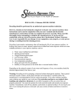
1
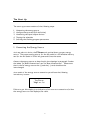
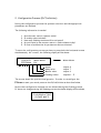
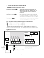
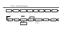
abc
The Filtron
User’s Manual
Ver. 3.6
Table of Contents
Page No.
3
3
4
5
Introduction
What is the Filtron?
The AC and DC Models
Using the Keyboard
The Start-Up
1. Connecting the Energy Source
2. Configuration Process (PLC Definition)
The Number of Filters
Master Valve
Delay Valve
Alarm
Water Meter
3. Connecting the Input/Output Devices
DC Board Connections
AC Board Connections
4. Testing Solenoids and Setting Parameters
Testing the Solenoids
Setting the Flushing Cycle
Setting the Dwell Time
Setting the Valve Delay
Setting the Flushing Time
The Differential Pressurestat (DP)
The Master Delay
6
6
7
8
8
8
8
8
9
9
10
11
11
12
13
13
13
13
14
Process Monitoring and Manual Actions
The Main Screen
Manual Start/Stop
Various Counters
Water Accumulation
Clearing Accumulators
Checking the Battery Level
Manual Pause
Low Pressure Halt
14
14
16
16
16
17
17
17
18
Timing Diagram
PLC Definition / Pop-up Screens
Full Screen Diagram
18
19
20
2
Introduction
What is the Filtron?
The Filtron has been specially designed for filter flushing control and you will
soon find out that it has very unique features:
!
Available in both DC or AC models
!
Reading:
!
!
1 differential pressurestat
1 water meter
1 low pressure detector
User defined configuration includes:
Main valve
(yes/no)
Delay valve
(yes/no)
Water meter
(yes/no)
Alarm
(yes/no)
Number of stations (yes/no)
All user parameters are user definable, namely:
Flushing cycle
Flushing time
Dwell time
Differential pressurestat delay
The number of successive operations considered as faulty operation
Master valve delay
!Solenoid
test mode
!Start
flushing according to time interval
!Start
flushing according to pressure difference
!Start
flushing according to volume measured by water meter
!Manual
!Real
!Full
start/stop of flushing sequence
time activity display
activity monitoring includes:
Number of manual activations
Number of time based activations
Number of differential pressurestat activations
Number of volumetric activations
3
!
Water meter accumulation
!
Detecting and eliminating endless, circular repetitions
!
Automatic pause on low pressure
!
Activating alarm (if necessary)
The DC and AC Models
The Filtron is available in both DC and AC models. The two models differ in
the energy sources and in the types of solenoids used.
The DC model is powered from a 12V Alkaline battery and it activates 12V DC
latching solenoids. The DC model has very low power consumption.
The AC model of the Filtron is powered from a power supply unit which supplies
24V AC both for the controller and for the solenoids.
The AC model depends on the 24V AC for solenoid activation. This means that
when there is a power shortage activations will not take place and no information
will be lost.
In general the DC and AC models are similar with only a few differences. These
differences will be pointed out when applicable.
4
Using the Keyboard
The Filtron is equipped with a keyboard of 5 buttons, as shown below:
t
w
enter
8
u
The <enter>> key is in the center and the keys have arrows. Please note that there
are both horizontal and vertical arrows.
The <enter>>key is used for:
!
!
!
Entering (or accessing) the screen in order to change a value.
Confirmation after insertion of a numerical value.
Positively responding when there is a yes/no question.
The arrows are used for:
!
!
Movement between screens
Changing numerical values in the following ways:
The
The
The
The
upper arrow increases the value by one (1)
lower arrow decreases the value by one (1)
right arrow shifts the digits to the right
left arrow shifts the digits to the left
Exception: Pushing the two horizontal arrows simultaneously will bring you into the
“PLC definition” mode in which the configuration is defined by specifying
the various devices connected to the
5
Filtron.
The Start Up
The start up process consists of the following steps:
1.
2.
3.
4.
5.
Connecting the energy source
Configuration process (PLC definition)
Connecting the input/output devices
Testing the solenoids
Defining the flushing program parameters
1. Connecting the Energy Source
As in any electric device, the Filtron won’t work without a proper energy
source. The proper energy source for the DC model is a 12V Alkaline battery
and for the AC model it is 24V AC generated from the mains.
Connect the energy source as described in the drawings in paragraph 3 under
the labels “DC Board Connections” and “AC Board Connections”. Please note
that in the DC energy source the (+) and the (-) cords should not be
interchanged.
As a result of the energy source connection you will see the following
introductory screen:
The Filtron
Talgil ver. 3.6
Failure to get this display is an indication of an incorrect connection of either
the energy source or the display’s flat cable.
6
2. Configuration Process (PLC Definition)
During the configuration process the system’s structure and the appropriate
parameters are defined.
The following information is needed:
1.
2.
3.
4.
5.
Does the unit control a master valve?
Is a delay valve included?
How many flushing stations will be activated?
Do you intend to use a water meter to flush volumetrically?
In case of malfunction do you want an alarm activation?
To start the configuration process you have to press both the horizontal arrows
simultaneously. As a result, the following display will be shown:
12345678
FFFFFMVA
Water Meter
PLC
Water Meter
Alarm:
Delay valve:
Master valve:
Flushing valves:
output 8
output 7
output 6
outputs 1 – 5
The screen shows the previous configuration. In order to reconfigure the
Filtron to meet your needs, execute the PLC definition as described below.
Notice that configuration changes are not allowed during the flushing process.
If there are changes during the flushing process the below display will be shown.
FLUSHING ACTIVE
PLEASE WAIT!
7
Press the right hand arrow to begin the PLC definition process and the following
screen will be displayed.
FOR NEW PLC
PRESS <ENTER>
Press the <enter>
key and the following screen will be displayed.
NO. OF FILTERS
5
Use the “UP” arrow to set the proper number of filters and press <enter>
The following steps define whether or not your system is intended to control
a master valve, a delay valve, an alarm, or to read a water meter. Press the
<enter> key and a negative by any of the arrows for a positive response. The
definition screens for the A/M devices will be displayed as follows:
FOR MASTER VALVE
PRESS <ENTER>
FOR DELAY VALVE
PRESS <ENTER>
FOR ALARM
PRESS <ENTER>
FOR WATER METER
PRESS <ENTER>
When the configuration process is completed a screen will be displayed showing
the order of the solenoid connections of the various valves to the terminal board.
Press the <enter>
key to return to the main screen.
8
3. Connecting the Input/Output Devices
The Filtron recognizes three types of devices:
Differential Pressostat (DP):
Measures the pressure difference between the
inlet and outlet of the filter, indicating a need for
flushing whenever the difference rises above a
preset value.
Low Pressure Sensor (LP):
Detects low pressure situations when the flushing
isn’t effective and stops it. This can also be used for
synchronizing the flushing with the start of irrigation.
Water Meter (WM):
Measures the water volume flowing through the filters
defining the flushing sequence volumetrically.
Each Input device has its own connection point on the terminal board:
DP
LP
WM
is always connected to input no. 1 (IN1)
is always connected to input no. 2 (IN2)
is always connected to input no. 3 (IN3)
There are some differences between the AC and DC models in the way the I/O
devices are connected to the boards. The following drawings show the differences:
DC Board Connections
Filtron 8 DC
Keyboard and
LCD plug
Buzzer
Inputs 1 – 8
Outputs 1 - 8
Not Used
xxx
2
+oc
4
+oc
6
+oc
8
+oc
∙••
∙•• ∙•• ∙••
2
ic
4
ic
6
ic
••
••
••
8
ic
••
∙ • •
∙•• ∙••
+ G G
For Inputs
I – Input
C – Common
Input
-
∙••
∙••
••
••
••
+oc
ic
ic
ic
ic
1
3
5
7
+oc
+oc
+oc
1
3
5
7
SOLENOID
- +
battery 12V
NC
Red
Black
NO
c Black
o Red
+ White
White
9
••
Input 1: Differential Pressurestat
Input 2: Pressurestat
Input 3: Water meter
Each DC solenoid has three wires and each output connection on the terminal board has three
positions market (+, 0, C). The white wire is always connected to the (+), the red wire is normally
connected to (0) and the black wire connects to (C). In the instance of a normally closed valve
switch the positions of the red and the black wires.
AC Board Connections
The following wiring diagram shows the AC board’s power and I/0 connections. We added the
description of the wiring for an expansion card that can be added to expand the number of
outputs. Special attention has to be paid to the connection of the 24V AC to the expansion card.
The polarity is important, even though we are talking about AC.
Filtron 10 AC
Keyboard and
LCD plug
Buzzer
Outputs
1 - 10
Not Used
+ -
2
oc
xx
G
G
4
8
2
6
4 6
8 10
oc oc oc oc
••
•• ••
Inputs 1 - 8
••
•••
•••
••
••
•••
24V
AC
••
••
oc
oc
1
3
••
oc
5
•••
••
oc
7
1
5
7
3
G
220VAC
░░
░░
G
24V
░░
The transformer
is located below
the printed card
Inp1: D. P.
Inp2: Pressurestat
Inp3: Water Meter
Connect these wires
EXACTLY as shown
•••
•••
Expansion Board 12
Outputs 11 – 22
outputs
Brown
Brown
Blue
C
Blue
Connectors
12
oc
14
oc
16
oc
18
oc
20
oc
22
oc
••
••
••
••
••
••
••
24 V
AC
oc
11
10
••
••
••
••
oc
13
oc
15
oc
17
oc
19
••
oc
21
Each AC solenoid has two wires and each output connection on the AC terminal board has
two positions, one marked by an ordinal number and the other marked (C). The order of
connection of the 2 solenoid wires makes no difference as long as the proper solenoid is
connected to the proper output location.
4. Testing Solenoids
The Filtron is capable of testing the solenoids. Each solenoid is tested for opening and
closing in the DC model. The machine will automatically test the 8 stations sequentially.
Press the <enter> key to start the process.
Press <enter>
Test Solenoids
Failure
Success
Test Solenoid &
op No Connection
op/cl
Test Solenoid 1
cl ****OK****
- Meaning “open” or “close” according to the action being tested.
If you get a “no connection” message, check out the board connections. If no problem is
indicated then try to replace the solenoids.
In the AC model the solenoids are tested against being short-circuited. When a shortcircuit is detected, the solenoid is marked SHORTED and won’t be activated until the
Filtron is informed that the problem is solved. The first screen to the right of the
Introductory screen will notify us that the short-circuited solenoids and the same screen
are used for signaling the end of the problem, just push the <enter> key. The AC model
solenoids are continuously tested whenever activated.
5. Defining the Flushing Program Parameters
The parameters that dictate the flushing process will be defined in the following steps:
Answer the following questions:
1. If you are using a water meter, how will the volumetric flushing cycle be measured (in
cubic meters.
2. If you are using a water meter, what is its volume/pulse ratio?
3. In minutes, what is the flush cycle time?
4. In seconds, what is the dwell time?
11
5.
What is the valve delay time in seconds (if your system includes a delay valve)?
6. What is the required flushing time in seconds?
7. What should be the reaction delay to the change of status of the D. P.
(Differential Pressurestat)?
8. How many consecutive flushing sequences does it take to be considered a faulty
circular activity situation?
Setting the Flushing Cycle
The flushing cycle can be expressed in terms of time and/or volumetric units. The
first event to occur will cause the start of a flushing sequence and will reset both
the volumetric and time based counters. Flushing sequence caused by the D. P.
(Differential Pressurestat) will also reset both of the counters.
The possibility to express a volumetric flushing cycle depends on the existence of a
water meter. The screens dealing with the water volume and the water meter ratio
will not be displayed if the water meter has not been declared.
The following screen should be used to express the flushing cycle in volumetric units:
Water Volume
100 cm
This means that flushing will take place after each 100 cubic meters measured by the
water meter. The range is 1 – 999 cm.
The volume/pulse ratio of the water meter is defined in the following screen.
The fraction represents the volume measured by each meter pulse. The range is
1 – 1000/100 cm.
Meter Ratio
10/100 cm
The flushing cycle defines the interval between successive flushing sequences – while
using time units – and it is measured in minutes (1-9999). If a flushing sequence was
started for any reason, the countdown to the next cycle is reset. Setting the cycle to
zero means that the backflushing will not be time based but will depend on the D. P only.
The screen used for setting the flushing cycle looks like the following:
Cycle Time
100 Minutes
12
Setting the Dwell Time
The dwell time is the delay measured between flushing of two successive
stations. It is measured in seconds (1 – 99).
Dwell Time
5 Seconds
Setting the Valve Delay
When a delay valve exists in the system, you need to define the delay between
the actions of the flushing valve and the delay valve. The range is 1 – 99 seconds.
If the configuration does not include such a valve the following screen won’t
appear.
Valve Delay
10 Seconds
Setting the Flushing Time
The flushing time defines the period of time during which the flushing valve is
kept open. The range is 2 – 240 seconds.
Flushing Time
30 Seconds
The Differential Pressurestat (D. P.)
If the system contains a D. P. then the following two parameters must be defined.
The first parameter defines the delay needed for the D. P. to stabilize. This time
is measured in seconds (2 – 30) and it is set in the following screen:
D. P. Delay
4 Seconds
The second parameter defines the circular looping limit. The looping may be
caused by the D. P. remaining constantly “ON” causing as endless flushing loop.
The circulation limit (0 – 9) is set via the following screen:
D. P. Fault No. of
False Flushes – 4
If “O” is selected, the looping detection mechanism is suppressed.
13
When the limit is exceeded the Filtron will stop flushing by D. P. and continue
flushing by time or volume. If an alarm has been defined it will be activated.
The following screen will be displayed:
D. P. Fault Release
by <ENTER>
To resume normal operation simply press the <enter> key.
The Master Delay
The delay between the master valve and the first flushing valve is called master
delay and it is defined in seconds (0 – 99) in the following screen:
Master Delay
5 Seconds
Process Monitoring and Manual Actions
The Main Screen
The main screen supplies on line information about the current status of the system.
Therefore its appearance varies according to the actual situation. During the countdown
between flushing cycles it will have the following form:
To Next D. P. - Off
Start 83:21 minutes
We are informed about the time left to the next cycle (83 minutes and 21 seconds),
and the current reading of the D. P. (“OFF”).
When a water meter has been declared and you want to see how much water will pass
through the water meter until the next cycle just press the lower arrow and the
following screen will show the requested information.
Current Flow – 128
Left Volume - 23
Current flow
Volume left
Both the volumetric and the time based counters count backwards. The first to reach
0 count will cause the start of a flushing cycle during which the second counter is also
cleared.
During the flushing sequence the main screen displays the various stages of the process.
The following example shows the way the main screen will look when the starting cause
was the D. P.
14
When the reading of the D. P. changes the “Off” will be replaced by “On” and after
the “D. P. Delay” the flushing cycle will start.
Blinking
DP – On
Master Delay – 6
The master valve is open
Fi.-1
DP – On
V. Delay Time – 6
The master valve is open
Filter station 1 is open
Fi. – 1 DV DP – On
Flushing – 25
The master valve is open
Filter station 1 is open
Delay valve is open
Fi. – 1
DP – Off
V. Delay Time -3
The master valve is open
filter station 1 is open
Delay valve is closed
Fi. – 1
DP – Off
Dwell Time - 2
The master valve is open
Filter station 1 is closed
Fi. – 2
DP – Off
V. Delay Time – 9
The master valve is open
Filter station 2 is open
To Next DP – Off
Start 99:05 Min.
All valves are closed
When the master valve and/or the delay valve are not indicated the relevant screens
will not be displayed.
When the flushing cycle is in progress no configuration changes or solenoid tests are
allowed. Trying to execute one of these actions will result in the following message:
Flushing Active
Please Wait !!!
15
Manual Start/Stop
Go to the following screen, located to the right of the main screen, to start a manual
flushing cycle.
Manual Start
<Enter>
Pressing the <Enter> key will immediately start the flush cycle.
The flushing sequence, when activated, can be stopped manually by using the following
screen.
Manual
Stop
<Enter>
Various Counters
The Filtron counts the various flushing cycles. The results are displayed as follows:
Started by D. P.
Started Manually
DP – 156 Ti – 10
Ma 2 Vo - 16
Started by Time
Started by Volume
Water Accumulation
When a water meter is defined the water accumulation is displayed on a screen
appearing to the right of the counter screen.
Water Accumulation
120 c. m.
16
Clearing Accumulators
Press the center (Enter) key to clear the counters.
Erase Accum.
<Enter>
Checking the Battery Level
The battery level can be checked on the following screen:
Battery Voltage
12.58 volt
The battery level is automatically computer checked once per hour. When the voltage
drops below 10 volts the following warning appears on the screen:
Warning ! !
Low Battery
The Filtron ceases all activity when the voltage drops below 9 volts. The following
screen is displayed.
Closed ! !
Replace Battery
Manual Pause
If for any reason the Filtron remains idle for any length of time a manual halt could
be caused.
Manual
Pause
<Enter>
All activity, including manual activity will be unresponsive. When trying to reactivate
the flushing sequence the following screen will appear.
Release Manual
Pause First !!
The manual pause is not allowed when the flushing process is in progress. As long as
the system is in “pause” the buzzer keeps sounding as a reminder that the system is
halted and it is the responsibility of the user to free it from the “MANUAL PAUSE”
position.
17
To release the system from “pause” the same screen is to be used:
Manual Pause
Release <Enter>
To resume normal operation press the <enter> key again.
Low Pressure Halt
When a low pressure sensor is used it has to be connected to input no. 2 (IN2). When
the sensor’s contact closes (for at least one minute), it will stop the activity of the
Filtron. The following message will be displayed.
Pause
Sensor Halt
The Filtron will remain halted until the contact opens.
Timing Diagram
Timing Diagram
Main Valve
Delay Valve
Flushing Station 1
Flushing Station 2
Flushing Station 3
A B
C
B D B
A – Master Delay
B – Valve Delay
C – Flushing Time
D – Dwell Time
18
C
B
D B
C
B
P L C Definition
To enter PLC definition, simultaneously press the two horizontal arrow keys.
To main screen
12345678 W. Meter
FFFFFMVA PLC
To main screen
To main screen
for new PLC
Press <enter>
To main screen
<Enter>
No. of Filters
No. of Filter
Stations
For Master Valve Main Valve
Press <Enter>
Definition yes/no
For Delay Valve
Press <Enter>
Delay Valve
Definition yes/no
For Alarm
Press <Enter>
Alarm Device
Definition yes/no
For Water Meter Water Meter
Press <Enter> Definition yes/no
Remarks:
The screens dealing with water meter, main valve and delay valve will not appear unless defined PLC.
The main screen appearance will change according to the current status.
DP = on means existing pressure difference. DP = off means no pressure difference.
Pop-Up Screens for Special Situations
Low battery, the Filtron will continue functioning. Prepare to replace battery.
The battery voltage is below 9 volts. The Filtron stops. Replace the battery.
Waiting caused by low pressure sensor.
Warning !!
Battery Low
Closed !!
Replace Battery
Pause
Sensor Halt
Waiting caused by exceeding the limit of consecutive starts caused by the DP.
P. D. Fault Press
<Enter> Release
Whenever a range limit is exceeded, the range limits will be displayed.
Range Error !!!
___
___
When trying to start a manual sequence during manual pause condition.
Release Manual
Pause First !!
When trying to do PLC changes when the flushing process is in progress.
Flashing Active
Please Wait !!
19
Filtron – Full Screen Diagram
The Talgil
Filtron v3.0
Introduction Screen
Press <Enter>
Test Solenoids
____
Solenoid Test
Water Volume
c.m.
Set water volume
between flushings
Main Screen
Current status
Display
DP Fault No.
of False Flushes
Master Delay
Sec. ____
No. of consecutive
flushings considered
as fault
Delay between
main valve and
first station
To Next DP Off
Start __: __ Min.
Current Flow ____
Left Volume ____
Current flow rate and
volume left to next cycle
1
Meter Ratio
00/100 c.m.
Set water meter
ratio pulses/m3
Cycle Time
Min. ____
Set cycle
Interval
Dwell Time
Sec. _____
Set delay between
stations
Valve Delay
Sec. ____
Flushing Time
Sec. ____
Set valve delay
(if exists)
Set flushing time
per station
D. P. Delay
Sec. ____
Set reaction delay
to a change in D. P.
Manual Stop
Manual Start
<Enter>
manual start +
stop of flushing
cycle
Release <Enter>
Dp - ___ Ti - ___
Ma - ___ Vo - ___
No. of Starts:
Dp – by pressure
Ti – by time
Ma- Manual
Vo – by volume
Water Accum.
- - - - - c.m.
Water accumulation
Erase Accum.
< Enter>
Clearing starts
water counters and
water accumulator
Battery Voltage
12.10 volt
Battery voltage
display
Manual Pause
<Enter>
Manual
Pause and
release