1
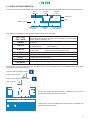
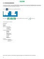
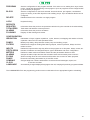
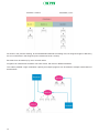
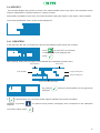
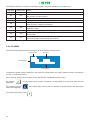
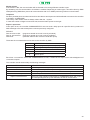
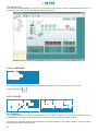
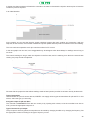
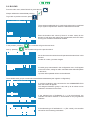
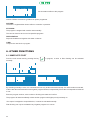
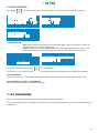
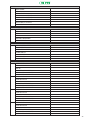
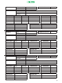
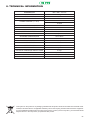
USER MANUAL
Commander EVO
GOLD
vB.1C eng.
2
INDEX
1
2
3
3.1
3.2
4
4.1
4.2
4.3
5
5.1
5.2
5.3
5.4
5.4.1
5.4.2
5.4.3
5.4.4
5.5
5.5.1
5.5.2
5.5.3
5.5.4
5.5.5
5.5.6
5.5.7
5.5.8
5.5.9
5.5.10
5.5.11
5.6
5.7
6
6.1
6.2
7
7.1
7.2
7.3
8
9
10
11
DESCRIPTION4
APPLICATION5
ELEMENTS INTEGRATING THE UNIT
6
SCREEN6
KEYBOARD7
FIRST CONTACT WITH COMMANDER EVO 400
8
INITIAL SCREEN
8
SOFTWARE VERSION
8
DISPLAYED INFORMATION
9
PROGRAMMING12
LOCK15
DELETING15
REPORTS16
REGISTERS17
ALARMS17
TOTALIZERS18
FLUSHING19
CONFIGURATION19
IRRIGATION19
PUMPS21
FERTILIZATION24
FLOW METERS
25
FILTERS26
INPUTS27
ALARMS29
FLOW31
COMMUNICATIONS31
CLOCK32
LANGUAGE34
PH & EC
34
BLOCKS36
PROGRAMS40
OTHER FUNCTIONS
44
IMMEDIATE START
44
DEACTIVATIONS45
MY PROGRAMS
45
MY CONFIGURATION
46
MY BLOCKS
48
MY PROGRAMS
50
TECHNICAL INFORMATION
51
CERTIFICATE OF CONFORMITY TO DIRECTIVES
52
WARRANTY53
NOTE54
3
1. DESCRIPTION
The COMMANDER EVO 400 is a powerful automatism, easy to program, designed to process and execute
automatically the functions of all existing elements in a modern irrigation control head, including Electric Conductivity
objectives in fertilization, acid or base injection referred to pH objective, filters flushing, fertilizer mixer, pumps, etc.
This unit is capable to manage the Automatic control of 24 outputs, even if they have different characteristics.
The large number of parameters that COMMANDER EVO 400 can handle makes it a controller practically adaptable
to most fertilization systems, able to manage all devices commonly used in them.
Programming COMMANDER EVO 400 by the user (data entering) is aided by a messages display that allows an
easy communication when entering data as well as when displaying them, making the controller comfortable and
easy to operate by the user.
This manual has been carried out by IRRITEC’S technical personnel for the use of its customers and its controller’s
users.
4
2. APPLICATION
COMMANDER EVO 400 controllers have been designed to drive the water and fertilizer application by time or
volume, with capability to control pH and EC among filter cleaning, pumps operation, alarms, communication, etc.
In the following schematic an example is displayed, where a COMMANDER EVO 400 controls an irrigation system.
COMMANDER EVO 400 controllers are configurable in function of the devices to be managed. So, in this example,
if there are not filters to be controlled, 4 more field valves can be used.
That capability allows adapting the controller to real needs of the irrigation system.
The COMMANDER EVO 400 controllers can communicate with modems and expanding units, collect information by
means of their digital inputs (flow meters, pressure switch, etc.), display reports of actuations and control the devices
installed in the system, as water pumps, fertilizers injectors, fertilizer mixer, filters and valves.
5
3. ELEMENTS INTEGRATING THE UNIT
3.1. SCREEN
It has a high resolution visualization display with 4 lines of 20 characters each (lit in 220VAC models)
This screen will help us to program the irrigation Schedule, to configure the unit to adapt it to installation’s needs and
to look up all functional parameters.
At stand-by (when no operation is done) the COMMANDER EVO 400 shows this screen:
08:32
R:0130 EC:0.2 PH:7.2
In that screen, among displaying the actual time, it displays the radiation, electric conductivity and pH values as read
by the analogues electrodes attached to the controller.
In addition, it presents in its STATUS SCREEN all events that take place in the irrigation system in real time.
This information will be of vital importance to perfectly configure the controller, looking for a balance to keep the
irrigation system in correct order and saving water, fertilizers and electric energy.
6
3.2. KEYBOARD
Commander EVO
www.irritec.com
Designed robust to withstand the hard conditions commonly found in the field, COMMANDER EVO 400´s keyboard
allows easy and intuitive access to all functions.
All keys have very clear assigned functions and its operation is very easy.
allow to gain access manually to start and stop menu.
Goes to irrigation schedule programming.
Goes to blocks/valves programming.
Goes to device´s configuration.
Goes to the main menu.
Allows to alternate answers in questions with several options (YES/NO, days of the week, etc.) It also
shows controller’s firmware version.
Easy the displacement between different menu and data input.
Allows going back in case of mistakes or to a previous screen.
Goes to alarms screen and to detailed information about the actual condition of different parameters
controlled by the unit (active inputs and outputs, pH and EC control, volume, fertilization time, filtration…).
7
4. FIRST CONTACT WITH COMMANDER EVO 400
4.1. INITIAL SCREEN
Once energized the COMMANDER EVO 400, the first message displayed is:
08:32
R:0130 EC:0.2 PH:7.2
By default the controller does not have any data programmed and shows the time and radiation, EC and pH read.
The first time that it is energized the alarm signal appears. The controller is warning about a power failure.
That information can be checked by pressing
The following screen will be displayed:
ALARM:
PF
DElete alarm ?: NO
The alarm can be deleted by pressing
and get out from this screen by pressing
or
4.2. SOFTWARE VERSION
The COMMANDER EVO 400 is a “live” controller that can incorporate new performances as the market and users
require new applications.
As well as being a high performance controller, the elements connected to it can be upgraded and this may make
necessary to update the software version.
To verify the installed software version, press
from the initial screen.
The display will show the controller model, outputs, voltage, serial number and software version installed.
COMMANDER EVO
400-24-220
NS:26080210 VB.1C
IRRITEC
To get out from this screen, press
8
4.3. DISPLAYED INFORMATION
At any time can be seen at the screen what is the controller doing and the parameters read from devices connected to it.
Flushing
filters
Active
Fertilizers
Fertilizer
mixer
FLUX 08:32
F:M1234 MXR Q00000
P:1234
P01/0 0037 01h34m23s
Working pumps
Remaining
Volume
Active Program
And block
Actual time
Flow
Remaining Time
for the block
The information displayed by the controller whilst working is the following:
PRE / PUL
PAU / INCR
HH:MM
Activity information
Informs about processes in execution as: Pre-irrigation, Filters flushing,
Pause, Valves overlapping, etc.
Actual time
F:M1234
Working fertilizers:
M: master fertilizer
B:M1234
Water pumps:
M: Main pump
Q00000
MXR
P01/01
0000 00h00m00
Low power
1234: fertilizers
1234: auxiliary or secondary pumps
Flow
Fertilizer Mixer
Program and block in execution
Remaining volume and time for the current block
The controller indicates that power voltage is too low.
Furthermore, by means of the keyboard, the report screen can be acceded, where more detailed information about
the irrigation process is displayed.
To get to that information, press
To go forward, press
To go to the previous screen, press
To exit, press
---PH EC CONTROL--pH: 32% 5.1 (5.0) 02s
EC: 21% 1.0 (0.9) 04s
01-02-03-04
pH (acid or base) and EC parameters. Working rate as well as
reading and objectives values are shown.
-------INPUTS------M
7
Active inputs. In the next table there is a description of data that can
be displayed on this screen.
9
LEYENDA
C
M
3
4
5
6
7
8
9
10
11
12
-----RADIO 200-----12
-----EXTENSION----07 09
-------OUTPUT------01 02
------fertiliz.-----f1 00h00m00 0000
f2 00h00m00 0000
f3 00h00m00 0000
------fertiliz.-----f4 00h00m00 0000
FUNCIÓN
Water meter/Counter
Differential pressure switch
Configurable 1 / fertilizer meter 1
Configurable 2 / fertilizer meter 2
Configurable 3 / fertilizer meter 3
Configurable 4 / fertilizer meter 4
Configurable 5
Configurable 6
Configurable 7
Configurable 8
External input (EX)
Configurable 9
Via radio operated valves, actives in this moment and the
correspondent radio group (if any has been programmed)
Active valves, correspondent to extension units. (if any extension
unit has been programmed)
Active outputs.
Remaining volume and time for each fertilizer in the block that is
currently in irrigation (Fertilizer Master is not shown).
-------WAITING-----Shows any program waiting for irrigation as one program with
higher priority has been activated (priority level is same as program
number).
10
----SUSPENDED---03
This indicates that a program has been set in pause mode because
of a higher priority program, or activation/pause caused by an
external input assigned to it.
-----FILTRATION ----fa v=0000 T=00H00M00
Filter flushing status.
------ANALOGUE -----ph 7.2
ec 0.2
temp:28
radi:0000
Actual values from the analogue electrodes connected to the
controller.
- - - - - - M I X E R- - - - - t=01m14s off
Remaining time to activate or deactivate the fertilizer mixer
--COMMUNICATIONS-tx:
rx:
Transmission and reception of data through the communication port.
11
5. PROGRAMMING
The first thing to check, once the COMMANDER EVO 400 is connected, is to verify that date and time are correct and
to introduce the data corresponding to the system configuration. The controller will, in the future, allow programming
it according to the initial configuration entered now.
Press
to enter in the programming screens.
programblock
deletelock
reportconfig
By pressing
choose the wanted option and press
to enter in it.
The menu tree is as follows:
PROGRAM
BLOCK
DELETE
LOCK
REPORT: REGISTER
TOTALIZERS
ALARMS
FLUSHINGS
CONFIG: IRRIGATION
PUMPS
FILTERS
INPUTS
FERTILIZERS
FLOWMETERS
ALARMS
FLOWS
PH&EC
COMMUNIC
CLOCK
LANGUAGE: ESPAÑOL
PORTUGUES
ENGLISH
Note: if the controller is executing an irrigation program, the configuration menu is disabled.
12
PROGRAM
Sets the configuration for the program selected: if it is active or not, starting time, days, blocks,
priority, inputs and alarms affecting to that program. Up to 20 programs can be configured with
up to 32 blocks per program.
BLOCK
Sets the configuration for the block selected: time and volume, pre-irrigation, combination/
groups of valves, pH and EC objectives and auxiliary pumps. Up to 64 different blocks can be
configured.
DELETE
Deletes all data in the controller or a single program.
LOCK Keyboard locking.
REPORTS
REGISTER TOTALIZERS
ALARMS
FLUSHING
Information about the previous 50 operations carried out by the controller in the selected day.
Total water and fertilizers volume per block.
Information about the previous 50 alarms.
Registry of filter flushing and causes.
CONFIGURATION
IRRIGATION
Delimitation of days, irrigation repetitions, cycles, demand, overlapping and rotation of blocks,
expansion valves and via radio operated valves.
PUMPS
Master pump delay, delay between master pump and auxiliary pumps.
FILTERS
Defines and configures existing filter flushing outputs, mode of operation, delays and time
relative to them.
INPUTS
Defines the inputs and the way they affect to the programs or to all system, delays, resets, etc.
FERTILIZERS Number of fertilizers and assigned outputs, type of fertilization and mixer configuration.
METERS
Defines the water meter and fertilizer meters and the parameters relative to them.
ALARMS
Assigns the alarm output and sets the activation issues and necessary time to shoot it.
FLOWS
Allows to assign flows to each valve that will be taken into account for alarm purposes.
PH&EC
Enters the necessary parameters for pH and EC control.
COMUNIC
Assigns telephone numbers authorized to receive and send messages, reports, etc.
CLOCK
To set time and date.
LANGUAGE
Automatically changes displayed language at the unit, keeping all previously programmed data.
The COMMANDER EVO 400 programming performs most combinations for an appropriate irrigation scheduling.
13
As shown in the previous drawing, at the PROGRAM is defined the starting time, but Program length is defined by
the sum of all blocks in that Program (hours:minutes:seconds / volume).
Each block can be made up by one or several valves.
Programs can share blocks as blocks can share valves, with same or different fertilizers.
This makes possible a high combination capacity as multiple programs can be related to multiple combinations of
blocks/valves.
14
5.1. CLOCK
To set the time and date in the controller, select CLOCK at the configuration menu.
CLOCK
TIME:
DATE:
12:17 MON
19/12 2005
Set the correct values using the keyboard and confirm each field.
To set the data those appear in the previous screen:
Press
as many times as necessary to select the day and
The initial starting menu will appear again.
5.2. LOCK
COMMANDER EVO 400’s keyboard can be locked by the user to avoid non authorized persons to access to the unit.
When selected at the main menu, the LOCK option will display:
PIN NUMBER: 0000
admin:26416
The COMMANDER EVO 400, by default, has a PIN number 0000.
Confirm that number (only if it has not previously changed by the user)
LOCK KEYBOARD: NO
When confirmed, the key character will be displayed and the controller will be locked, allowing only consulting reports
and functioning status.
To unlock the device, repeat the same process, confirming NO when the prompt LOCK KEYBOARD? appears.
15
Changing the PIN number:
At the second screen (LOCKING UNIT?) press
NEW PIN: 0000
In that moment COMMANDER EVO 400 gives the option to program a new PIN number.
Once changed the PIN, it shows the main programming screen and the controlled can be unlocked.
5.3. DELETING
A total or partial delete can be performed at the controller. Selecting the DELETE menu from the main menu, the
controller asks the following:
DELETE ALL: NO
DELETE PROGRAM: 00
DELETE ALL:
By selecting YS, the controller will ask again for confirmation (all data will be deleted).
ARE YOU SURE:
YS
When confirmed, all information will be deleted.
Along the deleting process the message WAIT is shown on the display.
ARE YOU SURE:
WAIT...
YS
DELETE PROGRAM:
Introduce the number of program to be deleted and confirm it. Deleting is instant.
16
5.4. REPORTS
This controller displays the previous 50 events, this makes possible to draw up a report. That information will be
useful to understand the controller behavior in a specific moment.
Report data are updated in each event. This means that when writing the registry 51 the registry 1 will be deleted.
Once inside the REPORT menu, the first screen displayed is:
REGISTER
TOTALIZER
ALARM
FILTERS
5.4.1. REGISTERS
In this sub-menu the user can access to the previous 50 operations performed by the controller.
Press
DAY TO
DISPLAY? : MON
as many times as necessary
to select the day to be displayed, then
press
When entering, always the last registry for the selected day is displayed at position H01).
Report position
Date (DD:MM)
Total volume
H01)
20/08
VA=0000
08:36 start
12:18
end
ACTIV: HO DEACTIV:EX
Program starting time
Program ending time
Cause of activation/ deactivation
f1=0000
f3=0000
If
F2=0000
F4=0000
By pressing
displayed.
, volumes of active fertilizers in the program are
is pressed again, the next report position appears (related to the previous actuation)
Otherwise, by pressing
operation.
To exit from reports, press
the previous report position is displayed, which corresponds to the subsequent
.
17
The different causes for activation / deactivation irrigation programs, displayed at the reports are:
Activation
Deactivation
Cause
HO
HO
Activation and deactivation have been performed due to irrigation schedule
EX
EX
Activation and deactivation have been conditioned by an external switch affecting to
the program or to all programs
TE
Activation has been performed by the programmed temperature parameters
RA
Activation has been performed by the programmed accumulated radiation parameters
TM
Activation has been carried out because the maximum time without demand was
reached (only in irrigation by demand)
MA
Activation and deactivation have been performed manually by the user through the
keyboard or SMS
AL
Deactivation has been performed by an alarm affecting the program.
PA
PA
The program has been deactivated by a pause order and activated by cancellation
of that order
FT
FT
Activation and deactivation have been performed by a power failure and activation
has been carried out when power was restored
MA
5.4.2. ALARMS
The last 50 alarms happened during irrigation can be checked in the next screen:
Report position
Date (DD/MM)
Alarm time
H01)
20/08
08:36
POWER FAILURE
Cause of alarm
The different causes of alarm displayed in this report are: power failure, flow meter, fertilizers meters, nominal flow,
pH, EC or external input alarm.
When entering, always the last registry for the selected day is displayed at position H01).
By pressing
happened.
, the next alarm report position is displayed, corresponding to the previous alarm that has
By opposite, pressing
alarm that happened.
To exit the alarm report, press
18
the previous alarm report position is displayed, corresponding to the subsequent
5.4.3. TOTALIZER
TOTALS WV=0000000
f1=00000 f2=0000000
f3=00000 f4=0000000
BLOCK TO
DISPLAY ? 01
BLOCK 01
f1=0000
f3=0000
Pressing
VA=0000
f2=0000
f4=0000
Summary where the total water volume and fertilizers volumes are
displayed (To set this registry to 0, a DELETE must be performed)
Pressing
, blocks details can be consulted.
In that detail are displayed water volume and fertilizers volumes for
the selected block.
, the controller will ask again which block number to display.
To exit from the report, press
It is advisable to perform a DELETE after making any changes in the parameters referred to meters constants as in
water meter as in fertilizer meters.
5.4.4. FLUSHING
-----FILTRATION----DP
TI
VO
MA
000 000 000 000
In this screen a report of all filters flushing is displayed, classified by
the causes that activated them. (Differential pressure switch, time,
volume or manual actuations)
To exit from the report, press
5.5. CONFIGURATION
The CONFIGURACION menu is where we indicate to the controller which devices are attached to it, and the mode
of communication with them. In this way, we suit the controller to the actual irrigation system.
Selecting CONFIG in the main menu or by pressing the key
options:
IRRIG
FILTERS
FERTIL
ALARMS
PUMPS
INPUTS
FLOWMETERS
FLOWS
PH-CE
CLOCK
EXIT
, the COMMANDER EVO 400 displays these
COMMUNIC
LANGUAGE
19
During CONFIGURATION we must indicate to the controller which output number corresponds to each specific use.
With the purpose to easy programming, it is advisable to fill the next table to assign the outputs. This information can
be useful at any moment.
USE
Uscita
MAIN WATER PUMP
AUXILIARY PUMP 1
AUXILIARY PUMP 2
AUXILIARY PUMP 3
AUXILIARY PUMP 4
MASTER FERTILIZER PUMP
FERTILIZER 1
FERTILIZER 2
FERTILIZER 3
FERTILIZER 4
ACID
BASE
MIXER
FILTER 1
FILTER 2
FILTER 3
FILTER 4
FILTER 5
FILTER 6
FILTER 7
FILTER 8
FILTER 9
FILTER 10
ALARM
It is advisable to use the higher output numbers in the controller in the same order shown at the attached table. For
example, Main water pump should be the 24 output and so on.
Note: At the end of this manual templates are provided. Fill and keep them in order to save the configuration
set in the COMMANDER EVO 400 controller for a future need.
To set the control elements used in the system, select the wanted option with the arrows and confirm.
20
5.5.1. IRRIGATION
(See also PROGRAM)
DELIMIT DAYS:
REPETITIONS:
CYCLIC: DEMAND:
NO
NO
NO
NO
OVERLAP / PAUSE: EXPANSIONS: NO
OVE
RADIO GROUP :200
TIME: 00S
NUM. OF TRANSM:03
BLOCK ROTATION:NO SIMULTANEITY: NO
Delimiting days
Answering YS, each program will ask for a date interval in between the irrigation program will be active.
Warning: starting date and ending date must be different. If those dates are the same irrigation will be performed
along the whole year.
Answering NO, programs will be active along the whole year, unless a cyclic irrigation is programmed.
Repetitions
Answering YS, the COMMANDER EVO 400 will display in each program the option to repeat it periodically (hh:mm),
as a pulsed irrigation
It is possible to repeat a program up to 99 times per day.
Cyclic
Answering YS, irrigation will be programmed according to cycles of days:
In the PROGRAM menu will be displayed the interval between irrigation days:
01 = diary
02 = each second day
03 = each third day
After it, the period in between the cycle will be performed (starting an ending day).
21
Demand
Answering YS, the option to start by demand will be displayed in each program.
Overlapping o Pause
Select if valves (groups of valves) must overlap or pause in the irrigation shifts
Overlapping time
Set the wanted time for OVERLAPPING/PAUSE in the operation.
As the diagram shows, Overlapping places one block that ends on top another block that starts during the overlapping time.
This function is useful to avoid water hammer in the system when irrigation valves are shifting.
PAUSE should be programmed, for example, when the system must keep pressurized to guarantee valve operation.
When overlapping/pause time is 0, deactivation of one valve and activation of next valve take place at the same time.
Radio Group
The controller COMMANDER EVO 400 is capable to codify the valves command protocol to be sent directly to an
ICT radio transmitter.
In this way the valve capacity is enlarged up to 96 radio controlled valves, among the wired ones.
By selecting YS in the configuration, at blocks menu the controller will ask, after the wired valves, for the radio
operated valves to be included.
000 = No radio.
100
= Used for wired expansion units.
200…900 = Radio group.
Setting the radio group the controller will ask for the two last digits of the valve to be included in the block. For
example, if radio group 200 is set, the radio group 2 will be displayed in the blocks and we must write the last two
digits for the valve (ex: 36 to enter the valve 236)
Number of transmissions
Indicate the number of times that orders to operate radio valves will be repeated
Note: It must be considered that each repetition is enlarging the transmission time, thus increasing the power
consumption and delay in operations. A balance must be found between safe operation and transmission
time as delays in valve operation can affect to system pressure.
22
Blocks rotation
Sometimes, the user doesn’t like to irrigate at the same hour in the same area every day, and a cycle program will do
that. To avoid it, rotation of blocks can be set so the blocks inside a program will rotate their operation order.
In the following diagram we can see an example; it is a system that irrigates 4 blocks for 4 hours each.
Block 3 is always irrigating when sun radiation is higher.
The Blocks rotation avoids that, setting the order as displayed on the next table.
ATTIVAZIONE
SEQUENZA DEI BLOCCHI ATTIVATI
1 attivazione
1
2
3
4
2 attivazione
2
3
4
1
3 attivazione
3
4
1
2
4ª attivazione
4
1
2
3
5 attivazione
1
2
3
4
...
2
3
4
1
ª
ª
ª
ª
Extension units
The COMMANDER EVO 400 can be extended by means of extension units up to 96 wired outputs among the 24
built in it.
Setting YS in the configuration, at the block menu will appear another screen asking for the valves to be set
corresponding to extension units. The extension unit group is always 100.
Simultaneity
This option, when set to YS, allows irrigating 4 different programs simultaneously. During simultaneity irrigation each
one of the 4 programs can manage the auxiliary pump and fertilizer correspondent to the same number of program,
in this way:
- Program 01 actuates pump 01 and fertilizer 01
- Program 02 actuates pump 02 and fertilizer 02
- Program 03 actuates pump 03 and fertilizer 03
- Program 04 actuates pump 04 and fertilizer 04
The blocks assigned to that programs must be different as well as valves assigned to that blocks.
In simultaneity mode, the following options are disabled:
- Flow control
- Delay between pumps
- Proportional or sequential fertilization or EC control
- Irrigation by volume
- pH control
23
5.5.2. PUMPS
PUMP OUTPUT: 24
DELAY: NEG 00 SEC
DELAY TIME BETWEEN
PUMPS: 12 SEC
AUX P.1:23 AUX P.2:22
AUX P.3:21 AUX P.4:20
Pump output
Assign the output for the main pump.
Delay
Indicate type of delay POSITIVE/NEGATIVE for the pump respect to valves actuation, and its time.
Note: In case of Negative delay, it will not be performed at the end of irrigation as it can not anticipate end of valves.
The COMMANDER EVO 400 can operate up to 4 auxiliary pumps to cover the system requirements of flow and pressure.
At the BLOCKS menu can be set the configuration for each of them.
Delay between pumps
(Disabled in simultaneity irrigation)
Due to electric or hydraulic requirements, it can be useful to delay the start of different pumps.
Auxiliary pumps
Assign the outputs that will drive the auxiliary pumps.
24
5.5.3. FERTILIZATION
ASSIGNED OUTPUTS:
f1=00
f2=00
f3=00
f4=00
FERTILIZER MASTER
OUTPUT: 00
TYPE OF FERT: PAR
(PARALLEL. SEQUENT.)
MIXER OUTPUT: 00
ON o1moos OFF iomoos
HOW ACTS: PREI
(ALWAYS. IRRIG. PREI)
TYPE OF FERTILIZ.: 0
0 = TIME/VOLUME
1 = EC CONTROL
2 = VOLUME/PROPORTION
Assigned outputs for Fertilizers
Set the outputs at which each fertilizer will be connected to the COMMANDER EVO 400
Assigned output for Fertilizer Master
If assigned, this output will be ON whilst any fertilizer is active. Commonly used for managing the fertilizer master
pump.
Type of Fertilization
By this option we can define if the fertilizers will operate in parallel or sequentially, regardless they work in time,
volume or proportionally
Note:If fertilizer duration is longer than block duration, fertilization will stop at block ending. If irrigation
simultaneity is selected, sequential fertilization is disabled.
Mixer output
Set if a fertilizer mixer will be used and the output controlling it.
25
Time ON/OFF
The mixer operates in an intermittent mode, so time to be ON and time to be OFF must be defined (minutes and
seconds)
Mode of mixing
Three modes of mixing are available in the menu: “mixing in irrigation”, “mixing in pre-irrigation” or “mixing always”.
Later on, at BLOCKS configuration, the COMMANDER EVO 400 will ask for each fertilizer according to this selection.
5.5.4. FLOW METERS
WATERMETER: LIT
CONSTANT: 01.0
FERT. METER: DL
CONSTANTS:
f1=00.0 f2=00.0
f3=00.0 f4=00.0
Water Flow Meter
The controller asks if a water flow meter exists. To set it, the measurement units must be defined (liters or m³).
Constant
Here must be indicated how many liters/m³ correspond to each pulse sent by the flow meter.
Fertilizer Meters
The controller requests for fertilizer meters. To set them, the measurement units must be defined (liters or dl)
Fertilizer Meters Constants
Here must be indicated how many liters/dl correspond to each pulse sent by each fertilizer meter.
Note: If fertilizer meters are defined, the controller will assign automatically input 3 to fertilizer 1, input 4 to
fertilizer 2, input 5 to fertilizer 3 and input 6 to fertilizer 4.
When these basic data for the meters are set, at the BLOCKS menu the rest of necessary data for fertilization must
be entered.
It must be taken into account that irrigation and fertilization by volume always depend on meters precision. This
means that never can be injected 12.4 liters of fertilizer if meter precision is 1 liter.
When irrigating or fertilizing by volume, the following data must be properly filled:
- Fertilizers outputs assignment
- Presence of meters (water / fertilizers)
- Flow meters constants assignment
26
5.5.5 FILTERS
FILTER FLUSHING: NO
SUSPEND: NO
COMMON VALUES: YS
DELAY: 00 MINUTES
Filter Flushing
It defines if the controller must operate filers flushing.
Suspend
Set if filter flushing suspends the irrigation, fertilization or does not suspend them. This can be used to guarantee
pressure during flushing or to avoid wasting of fertilizer whilst flushing.
Note: Suspending irrigation also suspends fertilization.
Common values
Set if flushing duration and pause between filters is the same for all filters.
By answering NO, the controller will request flushing time (minutes:seconds) and pause between filters for each filter.
This allows differentiating between different types of filters.
Delay
Set the time needed by the controller to execute a flushing from the previous one. In this case, the controller will
ignore any new command coming from the differential pressure switch before that time is over.
This function allows avoiding continuous flushing when variations of pressure happen, due to filling pipes at irrigation
start or after flushing.
This delay does not take into account the programmed interval between flushing. So, if a flushing is demanded by
scheduled time, it will be executed independently if delay is active or not.
27
TIME OF DETECTION
FOR INPUT MD ?: 05s
MAXIMUM N UMBER OF
FLUSH BY MD: 00
Time to detect MD (differential pressure switch) input
Set the minimum time that MD input must be ON to start flushing.
Maximum number of flushing by MD (differential pressure switch)
Set the maximum allowed number of consecutive flushing in the case of a permanent ON by MD.
FILTERS: 00
Filters
Set controller´s outputs to be used for filter flushing; they are defined one by one, confirming each one.
Maximum number of outputs for filter flushing is 10.
Note: to eliminate a filter previously set, simply introduce its same output number.
INTERVAL BETWEEN
FLUSHING
V=0000 T=00h00m
Interval between flushing
Set the period of time or/and totalized volume passing to execute a flushing. If the system has a flow meter, flushing
can be programmed to be done by time (hours: minutes) and by volume simultaneously as well as by differential
pressure switch (MD).
After each flushing, independently of its cause, internal data at the controller are reset:
FILTER TIME
00m00s
PAUSE TIME
00m00s
28
If values are common to all filters
FILTER TIME 01
PAUSE
FLUSH
=00m00s
=00m00s
If values are different for each filter
Flushing time
Set the time to be on the filter output.
This time (minutes: seconds) is defined as per specifications of filter type or water quality.
If “0 seconds” is programmed for a filter, the controller will not actuate on it, going from the previous one to the next
filter (this option can be useful when servicing or maintaining a filter).
When programming different times per filter, this screen will be displayed for each one.
Pause time
Set the pause time between two consecutive Filters in order to recover pressure in the network to guarantee an
effective flushing.
If pause time is set to 0 seconds, the controller will make it for 1 second.
When programming different times per filter, this screen will be displayed for each one.
5.5.6. INPUTS
INPUT (03)
AFFECTS ALL: NO
HOW AFFECTS: DES
DELAY: 000 SECONDS
INPUTS
The controller COMMANDER EVO 400 has 12 digital inputs that can be used for specific applications or can be
programmed by the user.
INPUT
FUNCTION
1
MAIN FLOW METER
2
DIFFERENTIAL PRESSURE SWITCH
3
CONFIGURABLE 1 / FERTILIZER METER 1
4
CONFIGURABLE 2/ FERTILIZER METER 2
5
CONFIGURABLE 3/ FERTILIZER METER 3
6
CONFIGURABLE 4/ FERTILIZER METER 4
7
CONFIGURABLE 5
8
CONFIGURABLE 6
9
CONFIGURABLE 7
10
CONFIGURABLE 8
11
CONFIGURABLE 9 / EXTERNAL INPUT (EX)
12
CONFIGURABLE 10
10 inputs can be configured by the user (6 if all fertilizer meters have been set).
Select the input to be programmed. It is advisable that some programming parameters being filled independently if
they affect to the whole controller or to a specific program.
29
Affects all
Set if that input will affect to the whole controller or to a specific program. In this case, in the program menu must be
indicated how this input affect (that program must be configured by demand)
How affects
- NO: Does not affect in any way.
- DEACTIVATING: The controller will deactivate all the programs. To re-activate them it must be necessary doing it
from each program menu.
- PAUSE: The program will be deactivated temporarily until the input returns to its normal condition. Irrigation time
and volume are kept.
- DEACTIVATE IF IRRIGATING: If there is any program irrigating, the controller will deactivate all its programs. To
re-activate them it must be necessary doing it from each program menu.
Delay
It is the time that an input must be active until the COMMANDER EVO 400 validates it.
INPUT (03)
PULSES: 05
TIME
RESET TIME : 00h00m
BETW. STARTS: 00h00m
Pulses
Maximum number of times allowed repeating a program affected by an input if this input is still active when program
is finishing.
The objective is to limit the consequences of malfunctioning in the demanding probe which can cause continuous
irrigation.
This parameter will be set accordingly to crop and probe characteristics.
Reset time
(Vedere figura seguente)
This is the time (hh:mm) that must pass between the first activation and probe status reading to activate the next
pulse in case the probe still demands it.
This data is necessary for demand probes, as this probe can be demanding to irrigate even for a while after the
irrigation pulse has been done.
Time between starts
This is the time (hh:mm) that must pass between the first activation and the next activation if after passing the reset
time the probe is still active.
30
5.5.7. ALARMS
ALARM OUTPUT: 00
TIME
WATERMETER PULSES
FOR ALARM: 10 MIN
NUMBER OF PULSES
FOR ALARM: 10
MARGIN EC:0.0 pH:0.0
T.ALAR EC:00M pH:00M
Alarm output
Set which output will be activated when COMMANDER EVO 400 enters in alarm status.
Time needed to shoot an alarm by meters
Set the maximum time without receiving pulses from the meters to shoot an alarm (Main pump does not start or
fertilizer tanks are empty, etc.)
Number of pulses from meters for alarm
Set a number of pulses received from meters to shoot an alarm if the meter should be stopped. This is to advise about
fertilizer leaking or malfunctioning in valve operation.
Error margin in pH and EC control
Set a maximum and minimum range respect to the pre-set objectives for pH and EC. Over that limits, the controller
will validate an alarm, acting as programmed.
Time for EC and pH alarm
Set the maximum allowed time to be reading pH and EC out of set range.
5.5.8. FLOW
FLOW CONTROL: NO
DELAY : 05 MIN
MAXIMUM ERROR : 05%
MINIMUM ERROR : 05%
Flow control
(Not available in simultaneity irrigation)
This screen can only be programmed if water flow meter exists.
The COMMANDER EVO 400 allows the user to assign a theoretical flow value to each valve.
If set, the COMMANDER EVO 400 will be always checking if the instant flow it is reading from the water meter
corresponds to the sum of flows from active valves irrigating in that moment.
By doing it, failures in valve opening, pump starting, pipeline bursts, etc. can be detected and the controller will act
as programmed.
There is a delay in control to avoid alarms when valves are shifting of filters are flushing or any event involving flow
changes is executed, the controller will not take it as an alarm if happened within this delay.
Flow measurements are done each 6 seconds by the controller.
Margin error
A margin error can be set as a % in differences between the theoretical flow and the actual reading flow.
This will be the maximum difference the controller should allow without entering in alarm mode.
Flow of each valve
Set the absolute nominal flow for each one of the valves using the units previously set in the meters configuration screen.
31
In the previous drawing can be seen how the actual flow varies from the nominal during overlapping and filling pipes.
In the shaded area, the controller will not take the measurements out of range into account. This is the programmed delay.
Note: To validate the alarm once the delay time is passed, the alarm must be active a minimum time that was
previously programmed in ALARM CONFIGURATION.
5.5.9. COMMUNICATIONS
The COMMANDER EVO 400 has a RS232 port that allows it to be connected to a GSM modem or to a PC.
The communication can be performed in two ways:
VOICE: By means of SMS messages protocol
DATA: Using the COMMANDER EVO PC software interface
SMS mobile phone connection
Some main commands can be used through a mobile phone using SMS messages: TO ASK, SEND COMMANDS,
TO RECEIVE ALARMS and TO RECEIVE REPORTS.
To have this option enabled, connect the controller to the GSM modem and configure the COMMUNICATIONS menu
in the controller.
modem:no
TEL1:+-------------TEL2:+-------------TEL3:+-------------32
REPORTS : NO
REPORT TIME : 00:00
Modem exists?
If the answer is NO, the communication will be directed to PC through RS232 controller’s port.
By answering YS, the communication via modem is enabled. Depending of modem type, it should be done by SMS/
GSM performing SMS/direct phone call communication with PC or GPRS performing Internet communication.
Telephone
Set the 3 possible phone numbers which will receive alarms and reports and will be allowed to access to the controller
to operate it via SMS/GSM.
The country code number must be always written after the + symbol.
In case that number of digits is lower than field, leave the blank spaces to the right.
Report / report time
If this option is set, the controller COMMANDER EVO 400 can send a daily report at a specific time by means of a
SMS message to the authorized phone numbers previously configured.
REPORT:
P05-15:00/15:34 HO (program 5 started 15:00 until 15:34 by schedule)
P02-10: 23/12:30 RA (program 2 started 10:23 until 12:30 by radiation)
INACTIVE
(controller status at the moment it sends the report)
These are the commands that can be sent to the controller by SMS:
COMMAND Description
Axx
Activate program XX (for example: 01)
Sxx
Stop program XX (for example: 02)
PSI
Pause the controller COMMANDER EVO 400
PNO
Get out from pause mode
H
Ask for report
Each time a command is sent to the COMMANDER EVO 400, it sends back a report as an acknowledgement of
command reception.
The controller sends automatically the following messages:
MESSAGE
Alarm power failure
Alarm flow meter
Description
Indicates power recovery after power failure
Time or number of pulses out of pre-set range established for flow meter alarm.
Alarm meter fx
Idem regarding the fertilizer meter indicated in the message.
Alarm ex input
External input nº 11 has been detected as alarm
Report: xxxxxxxxxxxxxx
Report of 5 last operations performed by COMMANDER EVO 400 is sent at
its corresponding time or by user demand, as well as current status.
33
Connection to PC
The controller COMMANDER EVO 400 can be connected to a PC directly or through a GSM/GPRS connection. In
this way, the controller can be full managed long away in real time.
5.5.10. LANGUAGE
ESPAÑOL
PORTUGUES
ENGLISH
To change controller’s language, select LANGUAGE (IDIOMA) in the configuration menu, choose the
language and press
.
5.5.11. PH & EC
EC DELAY : 20S
SENSOR TYPE: NOR
pH DELAY: 20S
OUTPUT pH:00 BASE:00
pH CTRL OUTPUT : FRE
EC CTRL OUTPUT : PUL
(FREQUENCY, PULSE, WIDTH)
EC and PH Delay
When injecting fertilizer according to EC objectives or acid or base to control pH, we must set a delay time for the
COMMANDER EVO 400 to read the EC and pH values and act as consequence of that reading.
The delay time will allow fertilizers and acid/base to be properly diluted in the irrigation water to achieve accurate
readings at electrodes insertion points.
34
A shorter time than necessary will make the controller to increase or decrease the injection amount prior to know the
result from previous injection.
In an ideal situation:
At the graphic we can see that injection speed variations happen after each reading and comparing it with the
objective, in that moment, the controller modifies the injection speed and it will produce a variation in the next reading.
This is a continuous operation as for pH control as well as for EC control.
In the next graphic we can see, in an exaggerated way, what happen when those delays in readings are too long or
too short.
The control is taking too long to reach the objective in the first case, and it is reaching it too fast in the second case
causing it to jump around the objective.
We must find the proper time that allows readings result of last injection just after it has been read by de electrode.
Type of transmitter
The transmitter is a part of sensor devices; IRRITEC can supply various types of transmitters for pH and EC. In this
screen, select the type you are using.
Assigned output for pH and Base
The controller COMMANDER EVO 400 can control pH by injecting acid or base, to let the controller know how to
work, just set the appropriate output for it.
Type of Control for pH output
The pH output is driven by pulses; those pulses can be varied by changing its width or by changing its frequency. Set
the appropriate control according to the type of injector you use.
35
5.6. BLOCKS
From the main menu, select BLOCK or press the key
Always validate the entered data pressing
To go back to previous screens, press
BLOCK NUMBER: 01
There are 64 possible blocks, in each block valves can be combined
as per system requirements. Select the wanted block number.
B01)
DURATION= 00h00m00s
VOLUME = 0000 m3
In this position, pressing And by pressing
Enter the duration and volume (if there is a water meter) for the
BLOCK. If both time and volume are programmed; the first of them
arriving to 0 will define the BLOCK duration.
the controller will go to the next block.
, the controller will go to the previous block.
B01) VALVES: 00
Set in this screen the valves that will operate at the same time in this
BLOCK.
To take off a valve, just enter it again.
B01) V.RADIO : 201
67 94
If a radio group was entered in the configuration menu, it will appear
in the next screen, asking for radio controlled valves that will operate
in this block.
Up to 96 radio operated valves can be selected.
The available radio groups are 200-300-400-500-600-700-800-900 (see irrigation configuration).
B01) V.EXTENSION: 101
5 36 45
B01) F01
DURATION= 00h00m00s
VOLUME = 0000 m3
B01)
EC INITIAL SPD.: 00%
OBJECTIVE EC: 0.0MS
FORMULA:00-00-00-00
36
If we have extension units connected to the COMMANDER EVO
400, this screen will appear.
The assigned extension group is 100, and up to 96 valves can be
selected to be entered in the block.
If the selected type of fertilization is = 0 (by time/volume), the
controller will ask for duration in time/volume for the programmed
fertilizers.
If the selected type of fertilization is = 1 (EC control), the controller
will ask for the necessary parameters.
EC INITIAL SPEED
The controller will try to reach the objective by a mathematic algorithm, always keeping the set proportion between
the different fertilizers.
If a value is entered (from 01 to 99) a starting point is set. In this way, the COMMANDER EVO starts the injection at
a speed previously set by the user. This can allow the controller to get the objective faster.
It is advisable to start irrigation with this parameter set to a minimal value and check in which value it remains during
the irrigation. Later, this value can be programmed in the BLOCK, so the controller will reach faster the objective
when operating that BLOCK.
In the previous drawings two different situations are shown, the first one at an initial speed of 10. When objective is
reached, we see at controller’s screen a speed of 32, if we enter a value of 30 for the block, the next time that block
operates it will start injection from 30 as shown in the second graphic, thus reaching objective earlier.
EC OBJECTIVE:
Set the objective EC in mili-Siemens for the final water-fertilizer solution.
FORMULA:
It is the proportion between fertilizers. This relation will be always maintained (discarding the ones set to 0)
37
The controller COMMANDER EVO 400 will be checking the actual value for CE it gets from readings against the
entered formula, increasing or decreasing the length of each pulse as a function of the distance to the objective.
In the graphic we see that fertilizer 3 remains open for a period, in those cases, fertilizers 1 and 2 don’t increase the
pulse, so they keep formula’s proportion entered by the user.
In cases like this, in which is difficult to reach the EC objectives, it is advisable to increase the fertilizer concentration,
so the fertilizer 3 will not remain working at 100% without reaching the EC objective, and proportion between 3
fertilizers will be maintained at all time.
B01)
VOLUME = 0000 LIT
INJECT 00.00 LIT
FOR 000.0M3 OF WATER
If the selected type of fertilization is = 2 (by volume/proportionality),
set in this screen what should be the proportion between water
and fertilizer, indicating the volume to inject and how many liters of
fertilizer must be injected per each m³ of water.
If selected type is Volume/Proportion or Time/Volume, all data parameters must be entered for each programmed
fertilizer.
In the next graphic is represented a simulation for an injection of 3 liters of fertilizer F01 per 1 m³ of water (3‰).
Each time that a pulse from water meter arrives, fertilizer pump number 1 is activated and remains activated until the
controller receives 3 pulses from fertilizer meter 1. In that moment the controller will deactivate the fertilizer pump until
receiving another pulse from water meter.
This process will continue until the set time or volume is finished.
38
B01)
PUMPS : 0 (1234)
PREIRRI.: 00 MIN
Set which auxiliary pump, from 4 available, will be activated within
this block and pre-irrigation or delay in minutes for fertilizers to
actuate with regard to valves.
As shown in previous drawing, pre-irrigation is the time when only water is applied before fertilizing.
If fertilization finishes before irrigation, the remaining time is the post-irrigation.
B01)
pH INITIAL SPD.:00%
OBJECTIVE pH: 0.0
pH initial speed:
Same as in EC control, user can set an initial speed for pH control.
With any type of fertilizer mode chosen, base or acid can be injected.
pH OBJECTIVE:
Set the wanted pH value.
Once entered data for chosen block, the next block will be displayed.
Up to 64 possible BLOCKS can be programmed in the COMMANDER EVO 400.
39
5.7. PROGRAMS
From the main menu select PROGRAM or press the key
Always confirm entered data pressing
To go back to previous screens press
PROGRAM NUMBER: 01
Select one from the 20 possible programs.
P01)
ACTIVE : NO
START TIME 00:00
IRRIG. DAYS: MTWTFSS
In this position, by pressing
And pressing
you can advance to the next program.
you can go to the previous one.
ACTIVE: Despite the program is fully configured, it only will operate by Schedule or demand if the program is
ACTIVE: YS.
If the program status is NO, it can only be started manually by the keyboard.
START TIME: Set the starting time for the program or the time from which this program is allowed to be started by
the demanding probe.
DAYS OF THE WEEK: Set the wanted days of the week in which the program will irrigate. To set them:
KEY 1 = Monday
KEY 2 = Tuesday
KEY 3 = Wednesday
KEY 4 = Thursday
KEY 5 = Friday
KEY 6 = Saturday
KEY 7 = Sunday
To eliminate one day, press on its corresponding key.
P01)
ACTIVE : NO
START TIME 00:00
IRRI. EACH 01 DAYS
If the COMMANDER EVO 400 was configured in CYCLIC mode, this
screen will appear.
In this case, set the interval in days to irrigate:
01= each day
02= each 2nd. day (1 day irrigates and 1 day not)
03= each 3rd. day (1 day irrigates and 2 days not)
etc.
P01)
FIRST DAY: 01/01/06
LAST DAY: 31/12/06
40
If DELIMITING DAYS have been set, this screen will appear. If not,
the program will irrigate along all the year.
By default the program will irrigate all year, set the limit if wanted and confirm them. Dates can be covered between
two years.
P01) BLOCKS: 00
Set the blocks to be operated sequentially inside the program. After
irrigation starts, the blocks will operate in the same order they were
entered. The maximum number of blocks per program is 32.
When more than 20 blocks are entered, the symbol “+” will appear at the end of screen.
To see the rest of blocks press
. Press the key
, to go back to previous screen.
If ROTATION OF BLOCKS was set, the irrigation order for the blocks will change every time the irrigation starts (see
IRRIGATION CONFIGURATION).
P01)
DEMAND: NO
TEMP > 00.0 C
RADIATION 0000WH/M2
An irrigation program can be activated by DEMAND due to one of
following causes: Temperature higher than preset value, accumulated
radiation or external input.
If all the three triggers are programmed, the first one achieved will activate the program.
DEMAND BY TEMPERATURE
In the next graphic can be seen how the temperature control performs on the irrigation program:
A hysteresis of 5ºC is internally pre-set under the programmed value. Only when temperature passes this point, the
controller will allow another irrigation start for the same cause.
DEMAND BY RADIATION
If a radiation probe is used, the controller COMMANDER EVO 400 can start irrigation programs according to
accumulated radiation parameters.
As shown in the graphic, the controller counts the accumulated radiation per sq. meter inside the programmed
interval. When the set value is reached, the irrigation is activated and the radiation meter is reset to zero.
41
As a consequence of it, the higher the radiation the lower the time is needed to start irrigation, thus the irrigation
frequency will be increased or decreased according to solar radiation.
By answering YS in the question DEMAND, the controller will ask the following:
P01)
END TIME : 00:00
MAXIMUM TIME:00H00M
A time to end is required. The starting time is established by demand.
Among it, a MAXIMUM TIME can be set. If the program doesn´t start
by demand once passed the maximum time set, the program will
start automatically.
This option will protect the crop against possible malfunctioning of the probe.
From the first moment and after each irrigation start, the internal clock for maximum time is activated. If there is a
demand before the internal clock arrives to the maximum time, the irrigation starts and the clock is reset to 0.
When working by simultaneity, two different programs cannot be activated by demand at the same time. For example:
we have two programs P01 and P03:
- If activated by temperature or external input, program P01 will start immediately and 1 second later program P03
will start.
- If activated by radiation, program P01 will start immediately and 1 minute later P03 will start.
P01)
PRIORITY: 01
INPUT: 00 ACTS: ACT
05 00H00H00 0H00H00
In this screen are defined the priority, the external input affecting the
program and how they affect to it. Are also displayed the remaining
resets, remaining time to next reading and remaining time until next
irrigation pulse validation (see input configuration).
The controller COMMANDER EVO 400 assigns to each program a
priority. When a program is irrigating, if another program with higher priority starts by Schedule or demand the lower
priority program will be paused until the higher priority program finishes.
Priorities are extremely useful in IRRIGATION BY DEMAND.
42
By default, priorities are defined as follows:
DEMAND BY EXTERNAL INPUT
PROGRAM 1
PRIORITY 1
PROGRAM 2
PRIORITY 2
PROGRAM 3
PRIORITY 3
...
...
PROGRAM 20
PRIORITY 20
A digital device can be used to act on a program. Up to 9 configurable inputs are available (6 if fertilizer meters are
configured)
Indicate the number of input that affects to the program and the way the input acts on it.
There are 2 possibilities of affecting:
ACT: Activates the program when the input is ON.
DES: Deactivates the program when the input is ON.
It is also possible to configure in the menu CONFIGURATION / INPUTS / HOW AFFECTS:
PAU: Pauses the program whilst input is ON.
The next screen indicates the number of repetitions and time between them.
P01)
REPETITIONS : 01
INTERVAL BETWEEN
REPETITIONS: 00H00M
Indicate how many times daily a program must be repeated and the
time between the repetitions. (only if repetitions have been set in the
main configuration menu).
In the next graphic an example of repetitions is shown. It is a program with one single block that irrigates 2 hours and
is repeated each 3 hours for 3 times, starting at 06:00
43
P01)
ALARM AFFECTS: NO
(NOTHING,STOPPING)
NEXT PROGRAM : 03
Set how alarms affect to this program
Indicare l’effetto che avranno gli allarmi in questo programma.
NOTHING:
The alarm is registered but doesn´t affect to controller´s operation.
STOPPING:
The program is stopped and must be reset manually.
This can be done for each one of 20 possible programs.
FERTILIZATION:
Stops the fertilizer but irrigation with water continues.
JUMP:
Jumps to the next block or program.
6. OTHER FUNCTIONS
6.1. IMMEDIATE START
From the main screen and by pressing the key
manually.
a program, a valve or filter flushing can be activated
ACTIVATE PROGRAM:00
ACTIVATE OUTPUT : 00
TIME : 00H00M00S
ACTIVATE FLUSH : NO
START VALVES
RADIO : 200
START VALVES
EXTENSION: 100
By activating manually a valve, it is connected and can only be disconnected manually. If a valve remains connected,
it will be also disconnected when next irrigation program finishes, independently if that valve corresponds to its blocks
or not.
Enter the program number, valve number or flushing to actuate and confirm.
The program will start immediately unless another program with higher priority is already on.
I fan output is assigned to a special device, it cannot be activated manually.
Filter flushing can only be activated if any irrigation program is in course.
44
6.2. DEACTIVATIONS
By pressing
from status screen, the controller, a valve or a program can be deactivated manually.
CHANGE STATUS : NO
STOP PROGRAM : 00
STOP OUTPUT
: 00
STOP VALVES
RADIO : 200
STOP VALVES
EXTENSION: 100
CHANGE STATUS:
STP Will set inactive all programs, to activate them again it will be necessary to confirm its activation one by one at the program menu.
PAU Will pause the controller COMMANDER EVO 400. All data will be kept in memory until pause is cancelled. At restart, the program will come back with data previous to pause.
12:06
IN PAUSE
CONTROLLER IN PAUSE
RESUME ?: YS
To get out from pause mode, press
and confirm again.
This option is very useful for small
servicing and maintenance without losing irrigation or fertilization.
STOP PROGRAM:
Stops a program even if it is irrigating, the program will keep inactive and its remaining irrigations will be lost
STOP OUTPUTS / V.RADIO / V.EXTENSION:
Stops the valves that have been activated manually.
7. MY PROGRAMS
To have a reminder of programmed data, it is advisable to fill the next tables.
This is a very helpful tool for consulting in the future and to solve technical problems trough our technical department
at IRRITEC.
45
7.1. MY CONFIGURATION
IRRIGATION
DELIMIT DAYS
REPETITIONS
CYCLIC
DEMAND
OVERLAP/PAUSE
OVERLAP
RADIO
NUMBER OF TRASMISSIONS
BLOCK ROTATION
EXTENSION
SIMULTANEITY
FERTILIZATION
NUMBER OF FERTILIZERS
OUTPUT F1
OUTPUT F2
OUTPUT F3
OUTPUT F4
ACIDO
BASICO
MASTER OUTPUT
TYPE OF FERTILIZATION
MIXER
TIME ON
TIME OFF
MIXING MODE
TYPE OF FERTILIZATION
EC DELAY CONTROL
PH DELAY CONTROL
TRANSMITTER TYPE
FILTER
FLUSHING
SUSPEND
COMMON
DELA
FILTER
VOLUME INTERVAL
TIME INTERVAL
FLUSHING
PAUSE
ALARMS
ALARM OUTPUT
ALARM METER
NUMBER OF METER PULSES
EC MARGIN
PH MARGIN
TIME FOR EC ALARM
TIME FOR PH ALARM
46
PUMPS
MAIN PUMP
DELAY
DELAY TIME
AUX PUMP. 1 OUTPUT
AUX PUMP. 2 OUTPUT
AUX PUMP. 3 OUTPUT
AUX PUMP. 4 OUTPUT
PUMPS DELAY
COMUNICATIONS
MODEM EXISTS
TEL 1
TEL 2
TEL 3
REPORT REQUIRED
REPORT TIME
METERS
MAIN WATER METER
K CONSTANT
FERTILIZER METERS
CONSTANT F1
CONSTANT F2
CONSTANT F3
CONSTANT F4
INPUTS
AFFECTS TO ALL
HOW AFFECTS
DELAY
NUMBER OF RESETS
T. BETWEEN OF RESETS
T. BETWEEN OF STARTS
AFFECTS TO ALL
HOW AFFECTS
DELAY
NUMBER OF RESETS
T. BETWEEN OF RESETS
T. BETWEEN OF STARTS
AFFECTS TO ALL
HOW AFFECTS
DELAY
NUMBER OF RESETS
T. BETWEEN OF RESETS
T. BETWEEN OF STARTS
AFFECTS TO ALL
HOW AFFECTS
DELAY
NUMBER OF RESETS
T. BETWEEN OF RESETS
T. BETWEEN OF STARTS
47
7.2. MY BLOCKS
DURATIO
NUMBER OF BLOCK
TIME
VOLUME
VALVE
WIRED
RADI
EXTENS,
FERTILIZERS
TIME
VOLUME
PROPORTION
PREIRRIGAT
F1
F2
F3
F4
CONTROL EC
CONTROL PH
Objective
Objective
Initial speed
Initial speed
Formul
DURATIO
NUMBER OF BLOCK
TIME
VOLUME
VALVE
WIRED
RADI
EXTENS,
FERTILIZERS
TIME
VOLUME
PROPORTION
PREIRRIGAT
F1
F2
F3
F4
CONTROL EC
CONTROL PH
Objective
Objective
Initial speed
Initial speed
Formul
DURATIO
NUMBER OF BLOCK
TIME
VOLUME
VALVE
WIRED
RADI
EXTENS,
FERTILIZERS
TIME
VOLUME
PROPORTION
F1
F2
F3
F4
CONTROL EC
CONTROL PH
Objective
Objective
Initial speed
Initial speed
Formul
48
PREIRRIGAT
DURATIO
NUMBER OF BLOCK
TIME
VOLUME
VALVE
WIRED
RADI
EXTENS,
FERTILIZERS
TIME
VOLUME
PROPORTION
PREIRRIGAT
F1
F2
F3
F4
CONTROL EC
CONTROL PH
Objective
Objective
Initial speed
Initial speed
Formul
DURATIO
NUMBER OF BLOCK
TIME
VOLUME
VALVE
WIRED
RADI
EXTENS,
FERTILIZERS
TIME
VOLUME
PROPORTION
PREIRRIGAT
F1
F2
F3
F4
CONTROL EC
CONTROL PH
Objective
Objective
Initial speed
Initial speed
Formul
DURATIO
NUMBER OF BLOCK
TIME
VOLUME
VALVE
WIRED
RADI
EXTENS,
FERTILIZERS
TIME
VOLUME
PROPORTION
PREIRRIGAT
F1
F2
F3
F4
CONTROL EC
CONTROL PH
Objective
Objective
Initial speed
Initial speed
Formul
49
7.3. MY PROGRAMS
PROGRAM NUMBER
ACTIVE
START TIME
END
WEEK DAYS
EACH X DAYS
START DAY
DEMAND
END DAY
TIEMPO MÁXIMO
BLOCKS
PRIORIT
NUMBER OF
IMPUT N°
ACTUATES
RIPETITIONS INTERVAL
ALARMS
PROGRAM NUMBER
ACTIVE
START TIME
END
WEEK DAYS
EACH X DAYS
START DAY
DEMAND
END DAY
TIEMPO MÁXIMO
BLOCKS
PRIORIT
NUMBER OF
IMPUT N°
ACTUATES
RIPETITIONS INTERVAL
ALARMS
PROGRAM NUMBER
ACTIVE
START TIME
END
WEEK DAYS
EACH X DAYS
START DAY
DEMAND
END DAY
TIEMPO MÁXIMO
BLOCKS
PRIORIT
NUMBER OF
IMPUT N°
ACTUATES
RIPETITIONS INTERVAL
50
ALARMS
8. TECHNICAL INFORMATION
DIMMENSIONS
320 x 250 x 130 mm
WEIGHT
3 Kg
ENCLOSURE
ABS
ISOLATION GRADE
IP-56
POWER SOURCE (+/- 10%)
230 VAC
12 VDC
INRUSH CURRENT 230 VAC/ 12 VDC
75mA / 15mA
CURRENT BY OUTPUT
20 mA.
CURRENT BY INPUT
8 mA.
INTERNAL BATTERY
NI-CAD 3,6V 110mA/h
BATTERY LIFE IN OFF MODE
1 year
WORKING TEMPERATURE
0ºC to 60ºC
AMBIENT HUMIDITY
0 a 95% not condensed
POWER SOURCE FUSES
2 Amp
OUTPUT TYPE
RELAY
OUTPUT FUSES
4 Amp
OUTPUT ISOLATION
8 Amp 4mm
OUTPUTS / ANALOGUE INPUTS FUSE
2 Amp
INPUTS
Opto-Isolated
INPUT ISOLATION
Optical
POWER LINE PROTECTION
Varistors
This symbol on the product or its packaging indicates that this product shall not be treated as household waste.
Instead, it should be taken to an applicable collection point for the recycling of electrical and electronic equipment.
For more detailed information about recycling of this product, contact your local city office, your household waste
disposal service or the shop where you purchased this product.
51
9. CERTIFICATE OF CONFORMITY TO DIRECTIVES
With this declaration, we confirm that COMMANDER EVO controllers in its models 90, 200, 400 y 500, for use in
irrigation systems control, comply with the applicable dispositions of the directives:
•
Electromagnetic Compatibility:
2004/108/CEE
•Electric Safety:2006/95/CEE
Verifying to fulfill the normative:
UNE-EN 61000-6-4:2007 EN 61000-6-3:2001
EN 61000-6-1:2001
Madrid, January 1st, 2011
J. Rubio
Tech. Manager
52
for electric safety
for conducted and radiated emissions
for electromagnetic immunity
10. WARRANTY
Products manufactured by Irritec have a limited warranty of 1 year from date of purchase.
This warranty covers possible manufacturing defects and Irritec guarantees COMMANDER EVO products against
manufacturing defects within a period of one (1) year starting from original date of purchasing. Irritec. recognizes
as its sole responsibility under this warranty to repair, replace with an equivalent product or to refund the paid
amount for the purchase of any product found defective within the warranty period, once received at Irritec, with
transportation charges paid by the sender, the product, copy of invoice and an explanation describing the problem.
If further information regarding the warranty is needed, call to the phone number 800 607050 or contact Irritec at the
address indicated at the end of this manual. This limited warranty does not apply to: (i) regular wear or aging of the
product, (ii) loss or damage due to accident, abuse, irrational use, misuse or negligence, (iii) damages caused by the
product or by the system in which the product is used or (iv) damages caused by maintenance or modifications made
in the product by personnel non authorized by Irritec.
THIS WARRANTY AND INPLICIT RESPONSIBILITY ARE EXCLUSIVE AND REPLACES ALL EXPLICIT OR
IMPLICIT WARRANTIES (INCLUDED ANY IMPLICIT COMMERCE WARRANTY WICH IS DISMISSED).
ANY WARRANTY APPLIED TO THIS PRODUCT IS LIMITED TO A PERIOD OF ONE YEAR. IRRITEC WILL NOT BE,
UNDER ANY CIRCUMSTANCE, RESPONSIBLE FOR ANY INCIDENTAL OR SUBSEQUENT DAMAGE, INCLUDED
BUT NOT LIMITED TO DAMAGES RESULTING AS A CONSEQUENCE OF MALFUNCTION OF THE PRODUCT
OR THE SYSTEM IN WICH THE PRODUCT IS USED, LOSS OF PROFITS OR REPLACING ELEMENTS. TO BE
EFFECTIVE THIS WARRANTY IS INDISPENSABLE ITS PRESENTATION FILLED AND STAMPED ACCORDINGLY
TOGETHER WITH THE PURCHASE INVOICE.
Model
Serial number
Installation date
Installation company stamp
53
11. NOTE
54
55
DAVISION.it DGBGMACCEG013300
Irritec S.p.A.
Via Gambitta Conforto, C.da S. Lucia
98071 Capo d’Orlando (Me) - Italy
Tel. +39 0941922111 - Fax +39 0941958807
www.irritec.com - [email protected]
DGBGMACCEG0 1 3 3 0 0