1
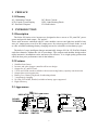
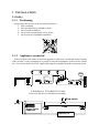
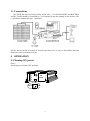
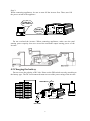
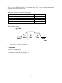
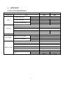
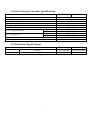
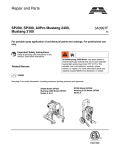
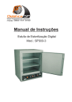
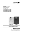
Solar off-grid Inverter SP Junior Series User Manual Contents 1 1.1 2 2.1 2.2 2.3 3 3.1 3.2 4 4.1 4.2 5 5.1 6 6.1 6.2 6.3 PREFACE .................................................................................... 3 Glossary.......................................................................................3 INTRODUCTION....................................................................... 3 Description ..................................................................................3 Features .......................................................................................3 Appearance ..................................................................................3 INSTALLATION......................................................................... 4 Safety...........................................................................................4 3.1.1 Positioning .........................................................................4 3.1.2 Appliances connected ........................................................4 Connections .................................................................................5 OPERATION ............................................................................... 5 Turning ON power ......................................................................5 Charging the battery ....................................................................6 STATUS MONITORING ........................................................... 7 Alarms .........................................................................................7 APPENDIX .................................................................................. 8 Inverter Specifications ................................................................8 Solar Charger Controller Specifications .....................................9 Mechanical Specifications ..........................................................9 1 PREFACE 1.1 Glossary AC: Alternating Current LCD: Liquid Crystal Display PC: Personal Computer DC: Direct Current LED: Light Emitting Diode PV: Photovoltaic 2 INTRODUCTION 2.1 Description The Solar SP Junior series inverters are designed to have access to PV panel DC power source and provide dual output – DC and AC. These mini-inverters combined with PV solar modules convert sun light into modified sine wave AC output power as well as DC output power for various types of electric loads, as well as offer selectable multistage battery charging current for selectable various battery types. The built-in 3-stage intelligent charger automatically charges Ni-Cad, GLE/AGM, flooded, sealed/wet batteries without the risk of overcharge. The compact and modular design makes utility interactive installations easier and more cost effective. It is a high quality product that offers the best price-performance ratio in the industry. 2.2 Features 1. 2. 3. 4. 5. 6. 7. 8. 9. Smallest form-factor Inverter and solar charger controller all-in-one design Output for AC and DC load 12Vdc and 24Vdc modes available with correct/wrong battery capacity auto-detection Output short circuit protection Battery Low, Battery Depleted, Overheating alarms 3-step battery charging Ni-Cad, GLE/AGM, flooded, sealed/wet battery types supported High efficiency 2.3 Appearance INDICATOR SOLAR TERMINAL DIP SWITCH USB PORT CHARGER DC LOAD ( ) TERMINAL 21 AC ON POWER OUTLET FAULT WA RN ING OFF DC LOAD TERMINAL ON POWER AC OUTPUT SOCKET SWITCH 3 ( ) TERMINAL FAN 3 INSTALLATION 3.1 Safety 3.1.1 Positioning Always place the inverter in an environment which is: 1. Well ventilated; 2. Not exposed to direct sunlight or heat; 3. Out of reach of children; 4. Away from water/moisture, oil or grease; 5. Away from any flammable substances. 3.1.2 Appliances connected If the total power (in watts) of electrical appliances connected, exceeds the output capacity of the inverter, or after operating for a period of time the temperature of the inverter reaches 60˚C, the inverter shall cut off AC output following the command from the protection circuit. 0 60 C . ※WARNING※ FLUORESCENT LAMP Do not use this device with fluorescent lamps. Glow switch a AC IN b Lamp Power Factor Capacitor BALLASTS 4 3.2 Connections CAUTION: Do not reverse the polarity of DC side. (+) of SOLAR PANEL and BATTERY and DC LOAD should be connected to (+) of terminal as per the printing on the inverter. The (-) should be connected to the (-) terminal. NOTE: Do not run DC load and AC load at same time, as it is easy to miscalculate the total load value and overload the inverter. 4 OPERATION 4.1 Turning ON power Step 1: Set the power switch at OFF position. CHARGER DC LOAD 21 AC ON POW ER OUTLET FAULT WA RN IN G OFF OFF ON ON 5 Step 2: When connecting appliances, be sure to turn ON the inverter first. Then, turn ON the power switch of the appliance. TURN ON SECONDLY AC OUTPUT 21 ON TURN ON FIRSTLY OFF ON Do not overload the inverter. When connecting appliances, make sure the total starting power capacity does not exceed the maximum output staring power of the inverter. 4.2 Charging the battery Do not reverse the polarity of DC side. Please set the DIP switch correctly according to the battery type. The DC load connected must not exceed the power rating of the inverter. DIP SWITCH 21 ON 21 AC ON OUTLET OFF SOLAR PANEL ON SOLAR INVERTER DC LOAD 6 BATTERY NOTE: Do not run DC load and AC load at same time, as it is easy to miscalculate the total load value and overload the inverter. DIP switch settings for different battery types: DIP switch 2 1 Bulk Float Battery Type OFF ON OFF OFF 15V 14V 14.5V 13.8V NI-CAD GLE / AGM OFF ON ON ON 14V 14V 13.5V 13.2V Flooded Sealed / Wet Solar charging stages: VOLTAGE 1 2 BULK PWM NIGHT 3 FLOAT NIGHT TIME 5 STATUS MONITORING 5.1 Alarms Inverter warning signal: Battery Low pre-alarm: bi---------bi---------bi Overheat pre-alarm: bi---bi---bi---bi---bi Overload pre-alarm: bi-bi-bi-bi-bi-bi-bi 7 6 APPENDIX 6.1 Inverter Specifications Model CAPACITY Watt Voltage range (DC) INPUT Current at full load Current in standby mode OUTPUT EFFICIENCY Voltage range (AC) Output wave form Frequency Continuous output power Peak output power Inverter efficiency Battery Low pre-alarm BATTERY Battery Low shutdown PROTECTION 12Vdc mode 24Vdc mode 12Vdc mode 24Vdc mode 12Vdc mode 24Vdc mode 12Vdc mode 24Vdc mode 12Vdc mode 24Vdc mode Thermal protection Auto-operating fan Overload protection Output short circuit protection Battery 12/24V mismatch protection Battery reversed polarity connection protection 12Vdc mode Fuse 24Vdc mode 8 SP300-Junior SP600-Junior 300W 600W 10 ~ 15Vdc 20 ~ 30Vdc 30A 60A 15A 30A < 0.5A < 0.6A < 0.4A < 0.4A 220 ~ 240Vac Modified sine wave 50 / 60Hz 300W 600W 900W 1500W 85 ~ 90% 10.5Vdc ±0.5V 21.0Vdc ±0.5V 10.0Vdc ±0.5V 20.0Vdc ±0.5V 60˚C ±5˚C Temperature or load dependent CPU controlled CPU controlled CPU controlled By fuse 35A 1 25A 3 20A 1 15A 3 6.2 Solar Charger Controller Specifications Model Standby Current Charger Current Max Solar Array Voc Max Solar Array Current Charging Stage Max Load Current 12Vdc mode 24Vdc mode 12Vdc mode 24Vdc mode Low Voltage Protection Low Voltage Reset Overload Protection Efficiency SP300-Junior SP600-Junior < 30mA 20A 50V 20A PWM Float 20A 10V ±0.5V 20V ±1.0V 12.5V ±0.5V 25V ±1.0V 120% of rated current > 90% 6.3 Mechanical Specifications Model Dimensions Weight LWH Net weight 9 SP300-Junior SP600-Junior 20017365 mm 1.6 kg 28017365 mm 2.8 kg