1
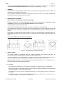
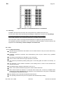
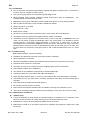
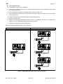
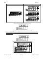
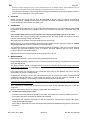
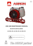
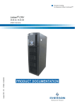
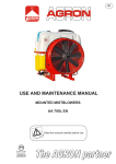
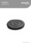
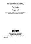
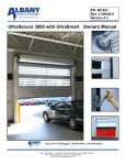
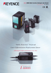
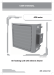
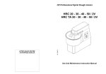
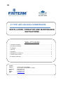
EN V-TYPE AIR COOLED CONDENSERS INSTALLATION, OPERATION AND MAINTENANCE INSTRUCTIONS Table of Contents 1. General Information…………………………………………………………………………… 1 2. Handling and Storage ……………………………………………………………………….. 1 3. Installation ……………………………………………………………………………………. 1 4. Start Up ………………………………………………………………………………………... 6 5. Operating ……………………………………………………………………………………… 6 6. Maintainance and Service …...………………………………………………………………. 6 7. Sound Pressure Level ……………………………………………………………………….. 7 8. Invalidity of Warranty .………………………………………………………………………… 7 Contact: Address Telephone Fax E-mail Web : Organize Deri Sanayi Bölgesi 18. Yol 34957 Tuzla İSTANBUL, TURKEY : (0216) 394 12 82 : (0216) 394 12 87 : [email protected] : www.friterm.com EN Page 1/7 This document specifies the instructions for installation, operating and maintenance of V Type Air Cooled Condensers (FUH VK models) manufactured by FRİTERM A.Ş., Turkey. 1. GENERAL The instructions below should be followed strictly for the health and safety reasons while installing and maintaining the equipments listed above. Upon receipt, the equipment should be visually inspected, and in case of any damage or deficiency, the supplier should be notified within seven days. 2. HANDLING AND STORAGE Check if there is any damage on product or package. Store the equipment in the original packaging in a dry area protected from the improper weather conditions or protect it from dirt and improper weather until final installation. Avoid exposure to extreme heat and cold. Avoid excessive storage periods (one year of storage at maximum is recommended). If the equipment is stationary for long periods in a humid atmosphere, the fans should be switched ON for minimum of two hours every month to remove any moisture that may have condensed within the motors. During lifting, a suitable lifting tool like a forklift or a crane is to be employed as in the drawings below. When lifting the equipment with hauling hooks, it is necessary to use a lifting beam connected to the hooks. Use a cotton lifting beam not to harm the equipment. Figure 1. Handling scheme during carriage 3. INSTALLATION The system installer is responsible that the inherent installation and security information are harmonized with the valid standards and guidelines (DIN EN 292 / 294). The EMC guideline is to be observed in connection with the control units. The manufacturer or operator of the entire plant is responsible for keeping to the EMC guideline 89/336/ EEC. Before installing, it should be ensured that the technical specifications of the equipment are in accordance with the desired working conditions. 3.1. Location The equipment is designed only for permanent installation. It should be fixed to a stable base. The working fluid, the maximum working pressure and the voltage declared by the manufacturer should be suitable for the working environment. The working area should be well ventilated and should not contain any hazardous substances or explosives. Air motion should not be adversely affected by obstructions and the inlet air should not be undesirably heated or cooled by the other equipment. Rev. Date: 18.01.2008 Rev.No:3 Doc.No: KLV.006.ING EN Page 2/7 Figure 2. Minimum recommended distances for installation 3.2. Mounting Installation and electrical connection are to be performed by qualified personnel only. Care should be taken while unpacking and installing the equipment to prevent from any damage. It must be ensured that no electrical supply connection exists during installation. The mounting position of the equipment should be in accordance with its design. The connections used for mounting should be adequate to support the total operational forces. The equipment should be mounted in such a way that no external vibration would be carried to the equipment and if necessary, vibration dampers should be used. 3.2.1. Fans 3.2.1.1. Safety Information The fans are only intended for the transfer of air or similar mixtures. They can not be used for any other purposes. Installation, electrical connection and commissioning must only be carried out by qualified personnel. (According to the definitions in DIN EN 50 110 or IEC 364) The fan can be used within the ranges specified on the label! The maximum permissible operating data given on the rating plate are valid for air density 1,2 kg/m³. The thermistor or PTC resistors mounted on the winding serve as motor cut-out switches and must be connected! Permissible testing voltage for thermistor is max. 2.5 V. Motor cut-out switch should be employed for motors without thermistor. EMC manual should be followed in connection with control units. If fans are completed with components of other manufacturers, the operator or the manufacturer of the plant is responsible for keeping EMC 89/336/EWG manual. Pay attention to the notes about maintenance and service. The operating instructions are part of the product and should be kept carefully. Rev. Date: 18.01.2008 Rev.No:3 Doc.No: KLV.006.ING EN Page 3/7 3.2.1.2. Installation Do not use metal compression-gland fittings together with plastic terminal boxes. If connection is incorrect, there is a danger of electric shock. Use a dummy plug seal for the compression-gland fitting as well. When operated under extreme conditions (humid environment, open air installations) installed sealing elements should be used pre- Depending on the type of cable gland, attach a water drain sleeve or use a sealing element. Bolt on plastic terminal box covers should be sealed with sealant. Starting torque for cover bolts Plastic version 1.3 Nm Metal version 2.6 Nm Secure fan connection cable to protection grille or motor struts, with cable fasteners. Thermistors and PTC resistors with triggering device must be connected Thermistors must be integrated in the control circuit in such a way that, if a problem occurs, the motor can not switch on again automatically after it has cooled down. It is possible to protect several motors by connecting motor’s thermistor in series with a control tool. It must be remembered that If temperature problem occurs at one motor, thermistor will stop in all motors Because of this, in practice, motors are assembled in groups. So if a motor goes out of order, only its group does not work and in emergency there is still a reduced performance even if a motor fails. 3.2.1.3. Commissioning Before initial operation, check the following; Installation and electrical connection have been properly completed. Safety equipment is in its place. All leftover installation materials and unfamiliar objects have been removed from fan cavity. Protective earth conductor is connected. Thermistor or motor cut-out switch has been installed properly and it is operational. Cable gland is sealed. (see ‘’installation’’) The position of the installation corresponds to condensed drainage. Connection datas are in accordance with label specifications. Motor operating capacitor data (1,~ motor) is in accordance with the specifications on the label. Commissioning may only take place if all safety instructions have been checked and danger is excluded. Check the sense of rotation and air feed direction. Be sure that running of motor is smooth. Check if there are intensive vibrations due to unbalance running (out-of-balance) or not. This may be caused by improper handling and bad storage. In such case, fan can not be used. 3.2.1.4. Maintenance and Service Outdoor Fans; If a fan is stationary for long periods in humid atmosphere, it should be run for minimum of two hours per month to remove any damp that may have condensed within the motor. Maintenance is only to be performed by qualified service personnel. Maintenance should be in accordance with service, operation and operator’s safety rules. (DIN EN 50110) Rev. Date: 18.01.2008 Rev.No:3 Doc.No: KLV.006.ING EN Page 4/7 During maintenance; Fan impeller must come to a standstill! Power supply must be shut down and secured against restoration. No maintenance work should be done at running fan. Do not clean the running fan with high-pressure cleaner. (‘’steam jet’’)! Do not wet-clean the fan when it is connected to the power supply; otherwise it can cause elektric shock. Risk of life! Keep the airways of the fan free because of objects dropping out! Record unusual noises. Replace the bearings in greasing period or if there is a breakdown. Consult to our maintenance guide or service department (special tools may be required.) Replace the bearings only with original parts. Electrical connection diagrams of fans are given below. CONNECTION OF A SINGLE FAN MOTOR CONNECTION OF MORE FAN MOTORS Z2 Z1 U2 U1 TK TK PE L1 N PE Z2 Z1 U2 U1 TK TK Z2 Z1 U2 U1 TK TK PE L1 N PE PE L2 N PE Z2 Z1 U2 U1 TK TK PE L3 N PE Figure 3. Ø500, Ø630 mm mono phase motor connection Rev. Date: 18.01.2008 Rev.No:3 Doc.No: KLV.006.ING EN Page 5/7 CONNECTION OF A SINGLE FAN MOTOR CONNECTION OF MORE FAN MOTORS TK TK W2 U1 U2 V1 V2 W1 PE T T L1 L2 L3 PE TK TK W2 U1 U2 V1 V2 W1 TK TK W2 U1 U2 V1 V2 W1 PE T T L1 L2 L3 PE PE T T L1 L2 L3 PE TK TK W2 U1 U2 V1 V2 W1 PE T T L1 L2 L3 PE Figure 4. Ø800 mm three phase motor connection Figure 5. Three-phase fan high rpm connection scheme Unless declared, three phase double speed fans are connected to the standard evaporators as operating in high speed. For low speed or double speed connection, following diagrams should be observed. Figure 6. Three-phase fan low rpm connection scheme K1 K2 W2 U1 U2 V1 V2 W1 PE T T 1L1 1L2 1L3 2L1 2L2 2L3 PE Figure 7. Three-phase double rpm motor connection Rev. Date: 18.01.2008 Rev.No:3 Doc.No: KLV.006.ING EN Page 6/7 Electrical connection diagrams for fans. The fans described above are of standard products. Other suitable fans may be used with the same basis. Refer to product catalogs for the diameters and the number of the fans. The electrical connection must comply with the relevant specifications and special attention must be given to correct installation of the ground wires. 4. START UP Before running the unit for the first time, be sure that all guards, motor mountings and electrical covers are secure, installation and electrical connection have been completed properly, internal wiring is clear off the fans and the fans can rotate freely. 5. OPERATING If the equipment is stationary for long periods in a humid atmosphere, the fans should be switched ON for minimum of two hours every month to remove any moisture that may have condensed within the motors. The recommended starting time for the fans is 6 times and maximum value is 10 per hour. While the fans are running, anything that could pass through the finger guards, like a piece of cloth or long hair, should be kept away from the fans. Stay away from the airways of the fans while the fans are running. Before touching, it is recommended to ensure that the headers and the connection pipes are neither too hot nor cold due to working conditions of the fluid inside. The operation should be stopped and the supplier should be consulted in case of any unusual working condition, like abnormal operating noise, is realized. Intensive vibrations due to out-of- balance running of the fans may lead to outage. Maintenance should not be performed while the equipment is in use. 6. MAINTENANCE Maintenance operation is to be performed by qualified personnel only. Please follow the safety regulations and the worker's protection rules by all maintenance and service work (DIN EN 50110). The fluid circulation should be stopped and it must be ensured that no electrical supply connection exists during maintenance. It is advisable to wait till the equipment comes to thermally balance with its surroundings if possible. If the tubes within the equipment or the connection pipes were to be repaired, the fluid in the line would better be poured out beforehand. Regarding the bearings, the fans are maintenance-free for 30-40.000 hours under normal operating conditions. Lifetime lubrication is valid within this period, and when this period is expired or the bearings are damaged, it is necessary to replace the bearings with original parts. If the fans are to be worked on for maintenance reasons, the instruction manual prepared by the fan manufacturer should be followed. Contact manufacturer if required. After maintenance is performed, ensure that no tools or other foreign materials are left in or near the equipment. Refer to Initial Starting before operating the equipment after maintenance. 6.1. Periodical Controls (Once a year) Corrosion on the fins and tubes should be inspected. If the tubes are worn-out, leakage may occur. The pipeline should be controlled for damage and leakage. Mechanical and electrical connections of the fans should be checked. Fans should rotate freely. Finger guard should be stable. All the fixings, especially fan motor mountings and equipment installation fixings must be ensured to be secure. Rev. Date: 18.01.2008 Rev.No:3 Doc.No: KLV.006.ING EN Page 7/7 6.2. When Necessary The surface of the heat exchanger should be inspected for dirt and dust, and if needed, should be cleaned by a soft brush, with the help of pressurized air, pressurized hot water or by a similar way. Care should be taken not to damage the fins and the fans. Chemicals that may react with the materials used in the equipment should not be used. Electrical connections and the fan motors should not be wet while cleaning. 7. SOUND PRESSURE LEVELS Sound pressure levels in dB at a distance of 10 m for different number of standard fans used in FRİTERM products (REF: EN13487). The test data are taken from fan manufacturers’ documents; the values given in the table above are only for comparison and the real values may be different due to the construction of the surroundings and installation characteristics. 8. INVALIDATION OF WARRANTY The warranty declared in the sales contract is valid only if the instructions given in this manual are not violated. Adres Telefon Faks E-posta Web Rev. Date: 18.01.2008 Rev.No:3 : Organize Deri Sanayi Bölgesi 18. Yol 34957 Tuzla İSTANBUL : (0216) 394 12 82 : (0216) 394 12 87 : [email protected] : www.friterm.com Doc.No: KLV.006.ING