1
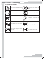
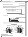
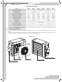
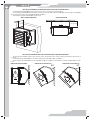
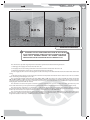
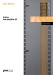
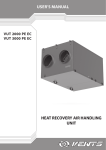
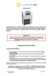
USER’S MANUAL
AOE series
Air heating unit with electric heater
2
CONTENTS
Safety requirements
Introduction
Use
Delivery set
Designation key
Main technical parameters
Design and operating logic
Mounting and set-up
Connection to power mains
Maintenance
Troubleshooting
Storage and transportation rules
Manufacturer's warranty
Acceptance certificate
Seller's information
Mounting certificate
Warranty Card
3
5
5
5
5
5
6
7
9
12
12
12
13
14
14
14
15
АОЕ
3
SAFETY REQUIREMENTS
•
•
•
•
•
•
Read the user’s manual carefully prior to the operation and installation of the unit.
Installation and operation of the unit shall be performed in accordance with the present user’s manual as well as the provisions
of all the applicable local and national construction, electrical and technical codes and standards.
The warnings contained in the user’s manual must be considered most seriously since they contain vital personal safety
information.
Failure to follow the safety regulations may result in an injury or unit damage.
Read the manual carefully and keep it as long as you use the unit.
While transferring the unit control the user’s manual must be turned over to the receiving operator.
Symbol legend used in the manual:
WARNING!
DO NOT!
UNIT MOUNTING SAFETY PRECAUTIONS
The unit must be disconnected from the power
supply prior to every installation or repair
operation.
The unit must not be operated outside
the temperature range stated in the user's
manual or in aggressive or explosive
environments.
Do not install heating equipment or any other
equipment close to the unit cable.
Do not use damaged equipment or
conductors to connect the unit to power
mains.
While installing the unit follow the safety
regulations specific to the use of electric tools.
Unpack the unit with care.
Do not change the power cord length at your
own discretion. Do not bend the power cord.
Avoid damaging the power cord.
Use the unit as intended only.
4
UNIT OPERATION SAFETY PRECAUTIONS
Do not wash the unit with water.
Protect the unit electric parts from water
ingress.
Do not carry out the unit maintenance with wet
hands.
ON
Do not block the air intake and exhaust vents
during the unit operation.
Disconnect the unit from power supply prior
to maintenance.
OFF
Do not let children operate the unit.
Do not damage the power cable while
operating the unit. Do not put any objects
on the power cable.
Keep combustible gases and inflammable
products away of the unit.
Do not open the operating unit.
In case of unusual sounds, smoke disconnect
the unit from power supply and contact the
service centre.
Do not let air flow from the unit be directed
to the open flame devices or candles.
АОЕ
5
INTRODUCTION
This user’s manual includes technical description, operation, installation and mounting guidelines, technical data for the air heating
unit with electric heater AOE, hereinafter referred as the unit.
USE
The unit is designed for air heating of medium up to large premises, such as industrial halls, storage facilities, workshops, sport halls,
trade halls, greenhouses, etc. The unit is designed for operation in moderate and cold climate conditions.
Transported air must not contain any flammable or explosive mixtures, evaporation of chemicals, coarse dust, soot and oil particles,
sticky substances, fibrous materials, pathogens or any other harmful substances.
THE UNIT IS NOT INTENDED TO BE USED BY CHILDREN, PHYSICALLY
OR MENTALLY DISABLED PERSONS, PERSONS WITH SENSORY DISORDER,
PERSONS WITH NO APPROPRIATE QUALIFICATION.
ANY OPERATIONS WITH THE UNIT MUST BE PERFORMED ONLY BY
PROPERLY QUALIFIED PERSONNEL AFTER THE APPROPRIATE SAFETY
BRIEFING.
THE UNIT INSTALLATION SITES MUST PREVENT ACCESS BY UNATTENDED
CHILDREN.
DELIVERY SET
AOE unit — 1 item;
User’s manual - 1 item;
Packing box - 1 item;
DESIGNATION KEY
АОЕ
ХХ
Electric heater power, kW
Unit type
AOE - electric heating unit
MAIN TECHNICAL PARAMETERS
The unit is designed for indoor application with the ambient temperature ranging from -30 °C up to +40 °C and relative humidity up
to 80%.
The unit is classified as a class I electrical appliance.
The unit design is regularly improved, so some models may slightly differ from those ones described in this manual.
UNIT OVERALL DIMENSIONS, MM
АОЕ 9, 12, 15
АОЕ 18, 24, 30
6
UNIT TECHNICAL PARAMETERS
Model
АОЕ 9
АОЕ 12
АОЕ 15
Supply voltage, 50 Hz [V]
АОЕ 18
АОЕ 24
АОЕ 30
3 ~ 400
Max. fan power [W]
140
Fan current [A]
253
0,61
1,1
Electric heater power [kW]
9
12
15
18
24
30
Electric heater current [A]
13,0
17,3
21,7
26,0
34,6
43,3
Total unit power [kW]
9,14
12,14
15,14
18,25
24,25
30,25
Total unit current [A]
13,6
17,9
22,3
27,1
35,7
44,4
3
Air capacity [m /h]
2300
-1
RPM [min ]
4000
1420
Casing material
1480
Painted steel
Noise level, 5 m, [dB(A)]
55
Ingress protection rate
61
IP 21
Weight [kg]
32
48
DESIGN AND OPERATING LOGIC
The unit is designed for indoor air heating by means of the electric heater and uniform air flow distribution with the fan and louvre
shutters.
The special unit design enables quick air heating in large premises due to high-efficient electric heater and a powerful fan. The electric
connections and control connections are performed in a terminal box at the side unit panel.
UNIT DESIGN
ELECTRIC HEATER
EMERGENCY THERMAL
SWITCH CAP
FAN
LOUVRE SHUTTERS
TERMINAL BOX
АОЕ
7
COLD AIR
WARM AIR
UNIT OPERATING LOGIC
The unit is equipped with two emergency thermal switches:
•
automatic self-resettable thermal switch with response temperature +50 °C.
•
manually resettable thermal switch with response temperature +90 °C. The manually resettable thernal switch is restarted by
pressing a button.
UNIT MOUNTING AND SET-UP
THE UNIT INSTALLATION IS ALLOWED BY QUALIFIED PROFESSIONALS AFTER
CAREFUL STUDY OF THE USER’S MANUAL.
While mounting the unit provide the minimum required access to the unit for maintenance and repair.
The unit is designed for wall mounting or mounting to any other vertical surface or ceiling mounting with fixing bracket.
While mounting the unit provide free air flow to the unit intake opening. The minimum distance from the wall or the ceiling to the
unit is 300 mm.
WARNING!
REDUCING MINIMUM DISTANCE FROM THE UNIT TO THE WALLS OR CEILING ADVERSELY
AFFECTS AERODYNAMIC AND HEATING CHARACTERISTICS AND THE UNIT SERVICE LIFE.
UNIT INSTALLATION WITH MKP-AOW MOUNTING KIT
The mounting kit MKP-AOW (available upon separate order) is used for ceiling mounting of the unit with mounting studs or chains.
The unit mounting example with the mounting kit MKP-AOW is shown below.
mounting stud
min 300 mm
8
UNIT INSTALLATION WITH THE MOUNTING BRACKET MK-AOW 25 AND MK-AOW 40
The mounting bracket MK-AOW (available upon separate order) is used for wall or ceiling mounting.
The mounting bracket MK-AOW 25 is designed for installation of the units AOE 9, AOE 12 and AOE 15G. The mounting bracket MK-AOW
45 is designed for mounting of the units AOE 18, AOE 24 and AOE 30.
Unit installation example with MK-AOW is shown below.
WALL SURFACE MOUNTING
CEILING MOUNTING
min 300 mm
UNIT INSTALLATION WITH MKU-AOW 25 AND MKU-AOW 40 MOUNTING BRACKETS
The mounting bracket MKU (available upon separate order) is designed for wall or ceiling mounting and installation at the angle of
30° and 45°.
The mounting bracket MKU-AOW 25 is used for mounting of the units AOE 9, AOE 12 and AOE 15.
The mounting bracket MKU-AOW 40 for the units AOE 18, AOE 24 and AOE 30. Unit installation example with MKU-AOW is shown
below.
MOUNTING AT RIGHT ANGLE
MOUNTING AT THE ANGLE 30°
30°
MOUNTING AT THE ANGLE 45°
45°
АОЕ
9
The unit operating area is shown below
4-14 m
3-8 m
16 m
16 m
CONNECTION TO POWER MAINS
DISCONNECT THE UNIT FROM POWER MAINS PRIOR TO ANY ELECTRIC
INSTALLATION OPERATIONS. CONNECT THE UNIT TO A CORRECT INSTALLED
SOCKET WITH A GROUNDED TERMINAL. ANY INTERNAL CONNECTION
MODIFICATIONS ARE NOT ALLOWED AND RESULT IN WARRANTY LOSS.
The unit must be operated only jointly with an automation system that enables the following functions:
1. Disabling power supply to the heater when the fan is off.
2. Air supply to the electric heating elements for heat removal within 2 minutes after the unit is off.
3. Maintaining minimum air speed 2 m/s to avoid heating elements overheating.
4. Power supply cut-off in case of overheating of the electric elements by means of the thermal switches mounted inside of the heater
casing
5. Automatic heating capacity control to keep the maximum air temperature downstream of the electric heater +40 °C to avoid the
heater overheating and reducing its service life.
The recommended suitable automation system for AOE 9, AOE 12, AOE 15 models is the control unit UET 15D and for the models
AOE 18, AOE 24, AOE 30 is UET 30 D. The control unit UET and the matching mounting kit are available upon separate order. In this case
replace the terminal box with a respective control unit and connect it to the internal terminal blocks of AOE unit in compliance with the
wiring diagram stated in the UET user manual.
The unit with a selected control system is rated for connection to three-phase ac 400 V / 50 Hz power mains. Connection to power
mains of the unit with any control system must be performed with insulated, durable and heat-resistant conductors (cables, wires).
The external power input 400 V / 50 Hz must be equipped with an automatic circuit breaker built into the stationary wiring to
disconnect all the power mains phases. The circuit breaker QF position must ensure free access for quick power-off of the unit. The circuit
breaker trip current must be in compliance with the current consumption of a specific AOE model.
The recommended circuit breaker trip current and the cable cross sections for various AOE models are given un the table below.
However, the conductor selection shall be based on the maximum permissible wire heating depending on the wire type, its insulation,
length and installation method (i.e. overhead, in channels or inside the walls).
10
Unit name
Rated circuit breaker trip current [A]
Number of conductors and cross section [mm2]
АОЕ-9
20
5х2,5
АОЕ-12
25
5х2,5
АОЕ-15
31,5
5х4,0
АОЕ-18
40
5х6,0
АОЕ-24
50
5х10,0
АОЕ-30
63
5х10,0
Enabling access to the unit terminal blocks:
1. Remove four screws from the terminal box lid.
2. Remove the lid.
1.
2.
TERMINAL BLOCKS INSIDE OF THE TERMINAL BOX
L
N
X1
in the control circuit
1L1
1L2
1L3
2L1
2L2
2L3
N
PE
X3
Fan
Terminals for
connection to the
contactor circuit
RT1
RT1
TK1
TK1
TK2
TK2
L
Terminals for
connection to the
control circuit
N
L1
L2
L3
N
PE
X1
in the control circuit
Terminals for
connection to the
contactor circuit
RT1
RT1
TK1
TK1
TK2
TK2
Terminals for
connection to the
control circuit
Install the jumper for
connection of TK1 and TK2 in
series
Install the jumper for
connection of TK1 and TK2 in
series
X2
Heater
X2
Heater
Terminal block X1 (in the control circuit):
RT1 – temperature sensor;
TK1 – self-resettable thermal switch (normally closed contact), response temperature +50 °C;
TK2 – manually resettable thermal switch (normally closed contact), response temperature +90 °C;
Connect the thermal switch contacts in series to the circuit of the starter (contactor) actuating coil that starts the unit or the heater. In
case of overheating one of the contacts gets broken and switches the starter actuating coil off to cut power off and stop the motor.
Terminal block X2 (heaters):
L1, L2, L3 – phases (for AOE 9,12,15);
1L1, 1L2, 1L3, 2L1, 2L2, 2L3 – phases (for AOE 18,24,30);
N – neutral;
PE – protecting grounding.
Terminal block X3 (fan):
L – phase;
N – neutral.
The fan, the heaters, the thermal switch and the temperature sensor are mounted on side of the unit, refer to the wiring diagram in page
11.
АОЕ
11
UNIT WIRING DIAGRAM
RT1
RT1
RT1
TK1
X1
TK1
TK2
TK2
RT1
RT1
RT1
TK1
X1
TK1
TK2
TK2
L1
L2
X2 L3
N
PE
L
X3
N
t°
S1
S2
Reset
E1
E2
E3
X4
yellow-green
1L1
1L2
1L3
2L1
X2
2L2
2L3
N
PE
blue
L
brown
M
C
black
АОЕ 9, АОЕ 12, АОЕ 15
X3
N
t°
S1
S2
Reset
E1
E2
E3
E4
E5
E6
X4
yellow-green
blue
brown
M
C
black
АОЕ 18, АОЕ 24, АОЕ30
The emergency thermal switches are actuated in case of unscheduled power outage or wrong selected control system.
The automatically resettable thermal switch with response temperature +50 °C resets to operating condition after the heater cooling.
Reset of the manually resettable thermal switch with response temperature +90 °C is as follows:
Disconnect the unit from power mains.
Let the heater fully cool down.
Remove the emergency thermal switch cap.
Press the Reset button using a rod of non-conducting material.
Troubleshoot the unit overheating and make steps to prevent it.
12
MAINTENANCE
Regular routine maintenance is required. The unit must be cleaned of dust once in year by means of air blushing. Disconnect the unit
from power mains prior to the unit cleaning.
TROUBLESHOOTING
Possible faults and troubleshooting
Fault
The fan does not start up
during the unit start-up.
Automatic switch tripping
following the unit turning
on.
Low air flow.
Heater malfunction.
High noise, vibration.
Possible reasons
Fault handling
No power supply.
Make sure that the unit is properly connected to power
mains and make any corrections, if necessary.
Motor is jammed, the impeller are
clogged.
ВTurn the unit off. Troubleshoot the motor jam and the
impeller clogging. Clean the blades. Restart the unit.
Overcurrent resulted from short circuit
in the electric circuit.
Turn the unit off. Contact the service centre.
Low set fan speed.
Set higher speed.
Control system malfunction.
Turn the unit off. Contact the service centre.
Control system malfunction.
Turn the unit off. Contact the service centre.
The impeller is soiled.
Clean the impeller.
The fan or casing screw connection is
too loose.
Tighten the fan or casing screw connection against
stop.
STORAGE AND TRANSPORTATION RULES
Store the unit in the manufacturer’s original packing box in a dry ventilated premise at the temperatures from +5 °C up to +40 °C at
the temperature +20 °C.
Storage environment must not contain aggressive vapours and chemical mixtures provoking corrosion, insulation and sealing
deformation.
Use hoist machinery for handling and storage operations to prevent the unit damage. Fulfil the handling requirements applicable
for the applicable freight type.
Transportation with any vehicle type is allowed provided that the unit is protected against mechanical and weather damage.
Avoid any mechanical shocks and strokes during handling operations.
АОЕ
13
MANUFACTURER’S WARRANTY
The manufacturer hereby warrants normal operation of the unit over the period of 24 months from the retail sale date provided the
user’s observance of the transportation, storage, installation and operation regulations.
Should any malfunctions occur during the unit operation through the manufacturer’s fault during the warranty period the user is
entitled to elimination of faults by means of warranty repair performed by the manufacturer.
The warranty repair includes work specific to elimination of faults in the unit operation to ensure its intended use by the user within the
warranty period. The faults are eliminated by means of replacement or repair of the complete unit or the faulty part thereof.
The warranty repair does not include:
•
Routine maintenance;
•
Unit installation / dismantling;
•
Unit setup.
To benefit from warranty repair the user must provide the unit, the user’s manual with stamped sale date and the payment document
certifying the purchase. The unit model must comply with the one stated in the user’s manual.
Contact your Seller for warranty service.
The manufacturer’s warranty does not apply to the following cases:
•
User’s failure to provide the unit with the entire delivery package as stated in the user’s manual or with missing component parts
previously dismounted by the user;
•
Mismatch of the unit model and make with the respective details stated on the unit packing and in the user’s manual;
•
User’s failure to ensure timely technical maintenance of the unit;
•
External damage to the casing (excluding external modifications of the unit as required for its installation) and the internal
components of the unit;
•
Alteration of the unit design or engineering changes of the unit;
•
Replacement and use of the unit assemblies, parts and components not approved by the manufacturer;
•
Unit misuse;
•
User’s violation of the unit installation regulations;
•
User’s violation of the unit control regulations;
•
Unit connection to the power pains with a voltage different from the one stated in the user’s manual;
•
Unit breakdown due to voltage surges in the power mains;
•
User’s discretionary repair of the unit;
•
Unit repair performed by any non-authorised by the manufacturer persons;
•
Expiry of the unit warranty period;
•
User’s violation of the established regulations specific to the unit transportation;
•
User’s violation of the unit storage regulations;
•
Wrongful acts against the unit committed by third persons;
•
Unit breakdown due to circumstances of insuperable force (fire, flood, earthquake, war, hostilities of any kind, or blockade);
•
Missing seals if provided by the user’s manual;
•
Failure to provide the user’s manual with the sale date stamp;
•
Missing payment document certifying the unit purchase.
FOLLOWING THE REGULATIONS STIPULATED HEREIN WILL ENSURE A LONG AND
TROUBLE-FREE OPERATION OF THE UNIT.
USERS’ CLAIMS SHALL BE SUBJECT TO REVIEW ONLY UPON PRESENTATION OF
THE UNIT, THE PAYMENT DOCUMENT AND THE USER’S MANUAL WITH THE SALE DATE
STAMP.
14
ACCEPTANCE CERTIFICATE
Product Type
Air heating unit with electric heater
Model
АОЕ
Serial number
Manufacturing date
Is recognized as serviceable.
The unit complies with the requirements according to the EU norms and directives, to the relevant EU-Low Voltage Equipment
Directives, EU-Directives on Electromagnetic Compatibility.
We hereby declare that the following product complies with the essential protection requirements of Electromagnetic Council
Directive 2004/108/EC, 89/336/EEC and Low Voltage Directive 2006/95/EC, 73/23/EEC and CE-marking Directive 93/68/EEC on the
approximation of the laws of the Member States relating to electromagnetic compatibility. This certificate is issued following test
carried out on samples of the product referred to above. Assessment of compliance of the product with the requirements relating to
electromagnetic compatibility was based on the following standards.
Quality Inspector’s
Stamp
SELLER’S INFORMATION
Shop name
Address
Telephone
E-mail
Sales date
This is to certify delivery of the complete unit with the user’s manual. The warranty terms are
acknowledged and accepted, the list of service centres is received.
Seller’s seal
Customer’s signature
MOUNTING CERTIFICATE
Air heating unit with electric heater has been connected to power mains pursuant to the requirements
stated in the present user's manual.
Company name
Address
Telephone
Installation technician's
full name
Installation date:
Signature:
This is to certify that the works specific to the unit installation have been performed in accordance
with all the applicable provisions of local and national construction, electrical and technical codes and
standards. The unit operates normally as intended by the manufacturer.
Signature:
Installation technician’s
company seal
АОЕ
15
WARRANTY CARD
Product type
Model
Air heating unit with electric heater
АОЕ
Serial number
Manufacturing date
Sales date
Warranty period
Sales company
Seller’s seal
2013
V98EN-01