1
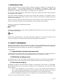
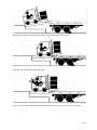
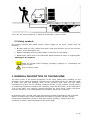
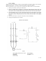
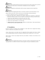
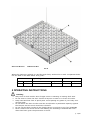
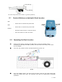
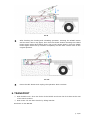
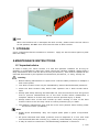
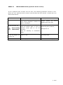
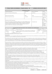
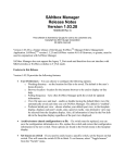
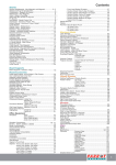
Hydraulic Dock Leveler
USER MANUAL
DELTA EQUIPMENT CO.,LTD
.
© 2004 All rights reserved.
www.hoangchuong.com.vn
Tel: 08.6264 6297
Only install or operate after reading manual in detail.
CONTENTS
1. INTRODUCTION … … … … … … … … … … … … … … … … … … ...3
2. SAFETY WARNINGS… … … … … … … … … … … … … … … … … 3
3. GENERAL DESCRIPTION OF THE MACHINE … … … … … ..7
4. INSTALLATION … … … … … … … … … … … … … … … … ..… … 12
5. OPERATING INSTRUCTIONS … … … … … … … … … … … … .14
6. TRANSPORT … … … … … … … … … … … … … … … … … … … ..16
7. STORAGE … … … … … … … … … … … … … … … … … … … … … 17
8. MAINTENANCE INSTRUCTIONS … … … … … … … … … … ..17
ANNEX I
ANNEX II
DAILY CHECKLIST 19
TROUBLESHOOTING (Hydraulic Dock Levelers) 20
p. 2/20
1. INTRODUCTION
Please read this manual carefully before starting,
Dock Levelers.
The manual describes the
maintenance of your Dock Levelers, as well as
precautions to be taken. Contact EP if you require
operating, repairing or maintaining the
installation, functioning, repair and
its use and the safety measures and
more information.
The operator and maintenance staff should read this manual and follow training before
working with this machine.
Keep this manual throughout the service life of the Dock Levelers. The operator and all
persons who come into contact with the Dock Levelers should read it regularly and have
access to it at all times.
Failure to comply with the safety instructions and warnings in this manual could result in
serious injury to the operator or other persons in the vicinity of the machine.
Dangers to people are indicated as follows:
warning
Points for consideration for the proper operation and long service life of your Dock Leveler
are indicated as follows:
note
People with responsibility for the safe and proper operation of this Dock Levelers must
use the procedures, working practices that are described in this manual.
2. SAFETY WARNINGS
While working with the Dock Leveler, the person who is responsible for supervising the
operation environment should take the necessary organizational measures to guarantee
the employees' health and safety as required by local legislation.
This includes:
2.1 Appointment of authorised personnel
Authorised personnel are staff who are permitted to operate a Dock Leveler according to
local statutory requirements and are appointed within the company to do this.
2.2 Definition of danger zone
The danger zone is the area within which people may be at risk from the movements of
the Dock Levelers. Only the operator of the Dock Levelers may be in the danger zone.
2.3 Prevention of injury
Operating procedures and instructions should be introduced, that as far as reasonably
practicable prevent the risk of injury to persons in the working area of the Dock Leveler.
These include:
Ø
never make adjustments to the machine if you are not trained and authorized to
do so; avoid making adjustments to the machine when the machine is moving;
never allow people near the Dock Leveler when you are carrying out work;
Ø
provide additional illumination if the visibility in the working area is restricted;
?
Consult your prevention adviser if desired.
p. 3/20
2.4 Operational Satety Precautions
Warning
2.4.1 Stay clear of dock leveller when freight carrier is entering or leaving area.
2.4.2 Do not move or use the dock leveller if anyone is under or in front of it.
2.4.3 Keep hands and feet clear of pinch pints. Avoid putting any part of your body near
moving parts.
2.4.4 Chock/restrain all fre ight carriers. Never remove the wheel chocks until loading or
unloading is finished and truck driver has been given permission to drive away.
p. 4/20
2.4.5 Do not use a broken or damaged dock leveller. Make sure proper service and
maintenance procedures have been performed before using.
2.4.6 Make sure lip overlaps onto trailer at least 4 in. (100mm)
2.4.7 Keep a safe distance from both side edges.
p. 5/20
2.4.8 Do not use dock leveller if freight carrier is too high or too low.
2.4.9 Do not overload the dock leveller.
2.4.10 Do not operate any equipment while under the influence of alcohol or drugs.
p. 6/20
2.4.11 Do not leave equipment or material unattended on dock leveller.
2.5 Safety symbols
All warning symbols and labels should remain legible at all times. Please note the
following:
Ø
to clean label use only a damp cloth and a mild soap solution; do not use solvents,
?
petrol, strong detergents etc.;
Ø
replace damaged and/or illegible labels; contact EP for new labels;
?
Ø
replacement parts must be provided with labels identical to those on original parts.
?
Meaning of the symbols
Read the manual before starting, operating, repairing or maintaining the
Dock Levelers
Risk of electric shock
3. GENERAL DESCRIPTION OF THE MACHINE
The Dock Leveler is the special equipment for the cargo loading and unloading, let the
operation of the material handling equipments are not influenced by the different height
of trailer bed with the platform, such as the forklift,it may drive into the trailer
compartment to carry on the handling operation directly, it only requires a single person
to complete the process of loading and unloading cargo fast and safely. It can help reduce
a lot of the labor cost, improve working efficiency by many times, obtain the better
economic efficiency, it is indispensable to the modern warehouse necessary.
EP Hydraulic Dock Levelers offer high performance,minimal maintenance and increased
safety for today’
s high volume loading dock area.Easy to operate hydraulic system
incorporates pushbutton control for both deck and lip operation, powered by a self
contained, 0.75kw/1.25hp maintenance free power pack.
.
p. 7/20
3.1 Components
The Hydraulic Dock Leveler (See Figures 1) is composed of the deck [4], the frame [8],
the Lip [1] and the hydraulic system [3,6 & 7], the electrical control box,etc.
The hydraulic power unit consists of the oil pump, the electric motor, the oil tank, the
relief valve and the reversing valve.
1.Lip
2.Lip Hinge
3.Lip Cylinder
4.Deck
5.Toe Guard Plate
6.Hydraulic Power Unit
7.Main Cylinder
8.Frame
FIG. 1
3.2 Technical features
EP Hydraulic dock levellers are available in the following sizes, capacities and options.
Width
6ft (1830mm) / 1800mm
7ft (2110mm) / 2000mm
Legnth
6ft (1830mm) / 2000mm
8ft (2210mm) / 2500mm
10ft(2820mm) / 3000mm
Capacity
25000lbs (12000kg)
30000lbs (14000kg)
35000lbs (16000kg)
Special needs available.
p. 8/20
The technical features of Hydraulic Dock Levelers listed below. Its main features can be
found on the type plate located the front bottom of the Dock Levelers.
1.
Model
2.
Capacity
DE -12HE-1820
DE -25HA-6.8
DE -12HA-2025
DE -25HA-7.8
DE -14HE-1820
DE -30HA-6.8
DE -14HA-2025
DE -30HA-7.8
DE -16HE-1820
DE -35HA-6.8
DE -16HA-2025
DE -35HA-7.8
12000KG
25000LB
12000KG
25000LB
14000KG
30000LB
14000KG
30000LB
16000KG
35000LB
16000KG
35000LB
3.
Platform Size
4.
Overa ll Size
5.
Height*
600mm
19”(24”)
600mm
19”(24”)
6.
Lip Board Width
450mm
18”
450mm
18”
7.
Travel (up)
300mm
12”
300mm
12”
8.
Travel (down)
300mm
12”
300mm
12”
9.
Motor
0.75kw
1.25hp
0.75kw
1.25hp
10. Oil
capacity
1800x2000mm
2000x2500mm
72”x87”(6’ x 8’)
tank
11. Input voltage
83”x87”(7’ x 8’)
5L
Available in all standard single and three phase voltage
12. Protection
degree (IPXXX)
13. System
pressure
IP 23
16 MPa
*The height means the height in lowered position.
3.3 Hydraulic system
The Hydraulic Dock Leveler contains the required hydraulic oil and hydraulic settings have
been installed at the factory.
note: Do not alter the settings of the hydraulic system; do not adjust the hydraulic
pressure.
p. 9/20
HYDRAULIC
SYSTEM DIAGRAM:
FIG. 2
1.
2.
3.
4.
Adjustable relief valve
Unidirectional inserted valve
Reversing valve
Throttle valve
3.4
5.
6.
7.
9.
Control valve
Adjustable throttle valve
Electric motor
Oil pump
Electrical system( hydraulic dock levelers)
3.4.1 Connection
warnings
Ø
Only a certified electrician may carry out the electrical installation of the
Hydraulic Dock Levelers.
Ø
Ensure good grounding of the switch box.
All wiring is in place. Attach a plug to the feeder cable; the Hydraulic Dock Leveler is not
fit to be directly connected to the mains.
note: The components in the switch board, such as contactors and power supply
function at this voltage rate only, and the AC engine was construed to function in the
voltage which you can find on the type plate.
p. 10/20
3.4.2 Testing
Switch the power ON briefly in order to verify whether the engine rotates in the direction
marked by the arrow. In order to reverse the engine, switch two phases.
When the ON button in the control box is inserted, the START button can be activated.
1. Switch power ON by pressing the ON button.
2. Press the START button constantly to activate the Main cylinder, and the deck rise
slowly until reach the top height. If you press the START button all the time, the
Lip cylinder will be activated after the deck reach the top. Then the lip will extend.
3. Free the START button, the deck will fall down and the lip keep silent. If you Press
the START button again, the lip will retract slowly. Free the START button again
when the lip retract completely and the deck will fall down and back to the original
position.
4. Press the OFF button: the power should be cut off immediately.
5. Unplug the Hydraulic Dock Levelers.
ELECTRIC
SYSTEM DIAGRA M
FIG. 3
M3-3-phase asynchronous motor
QF-Breaker
SB-Button
FR-Hot relay
KM-Contactor
TC-Transformer
FU-Fuse
p. 11/20
4. INSTALLATION
4.1 Prepare pit
Dimensions for Pit
Leveler Size
Dim “
A”width
Dim “
C”length
6’x
7’x
6’x
7’x
6’x
7’x
74’
85’
74’
85’
74’
85’
63’
63’
87’
87’
111’
111’
6’
6’
8’
8’
10’
10’
Leveler Size
(width x length)
1800mm x 2000mm
2000mm x 2000mm
2000mm x 2500mm
2000mm x 3000mm
A-DISTANCE(PIT
W IDTH)(F RONT AND
REAR)
Dim “B”depth
(rear)
19 1/2’
19 1/2’
19 1/2’
19 1/2’
19 1/2’
19 1/2’
Dim “
A”width
Dim “
C”length
1860mm
2060mm
2060mm
2060mm
2150mm
2150mm
2650mm
3150mm
B-DISTANCE(DECK FLOORTO PIT FLOOR)(ALL FOUR
CORNERS)
Dim “B”depth
(rear)
600mm
600mm
600mm
600mm
C-DISTANCE(PIT
LENGTH)(BOTH S IDES
OF PIT)
Dim “B”depth
(front)
20’
20’
20’
20’
20’
20’
Dim “B”depth
(front)
605mm
605mm
605mm
605mm
D-DISTANCE(PIT CORNERTO-C ORNER)(TOP ,
BOTTOM, AND BOTH S IDES
FIG. 4
p. 12/20
Warning
Post safety warning and barricade the work area at dock level and ground level to prevent
unauthorized use of the dock leveller before installation has been completed.
Warning
Only trained installation professionals with the proper equipment should install this
product.
Warning
Do not remove the shipping bolts fixed on the dock leveller lip until instructed to do so.
Before lowering the dock leveller into the pit, the following must be performed,
1. Remove all debris from the pit and sweep the pit clean
2. Check the entire dock leveller pit for proper construction according to approved /
certified pit drawing. Make sure pit is square by making the following measurements,
Ø
Measure pit width distance A at both front and rear of pit.
Ø
Measure dock floor-to-pit floor distance B at all four corners
Ø
Measure pit length distance C at both sides
Ø
Measure corner-to-corner(cross-cross) distance D at both sides. Take measurements
at dock floor level and at pit floor level.
4.2 Installation
EP dock levellers are designed with installation in mind. Each unit is shipped with lifting
bracket A fastened to the platform side joists.
Using a lifting device and chains with the appropriate lifting capacity and reach, Always
use the lifting brackets whenever lowering or lifting a dock leveller into or out of a pit.
Before lifting, remove any bumpers that may be banded or bolted to the frame of the
dock leveller.
Warning
Do not remove the shipping bolts B fixed on the Dock Leveller lip and frame this time.The
shipping bolts are needed to hold the leveller together during the installation process.
p. 13/20
A-LIFTING BRACKET
B-S HIPPING BOLT
FIG. 5
When the machine is placed in a pit floor and firmly anchored to it with 4 expansion bolts.
Use the data in the table below as a guide:
Bolt
Expanding tube
Hole
Spec.
Length
Outer diameter
Length
Diameter
Depth
M16
150 mm
22 mm
90 mm
23 mm
100 mm
5 OPERATING INSTRUCTIONS
warning
Ø
Ø
Ø
Ø
Ø
Ø
Stay clear of dock leveller when freight carrier is entering or leaving dock area.
Do not raise or lower the dock leveller if anyone is under or in front of leveller.
Keep hand and feet clear of pinch pints. Avoid putting any parts of your body near
moving parts.
Do not active the dock leveller until the truck/trailer is positioned squarely against
the bumper and the truck wheels are chocked.
Do not use the dock leveller if the freight carrier is too high or too low.(as FIG. 6)
Never remove the wheel chocks until loading an unloading is finished and truck
driver has been given the permission to leave.
p. 14/20
FIG. 6
The work range of EP dock leveller is
5.1
12 inch (300mm).
Controls Buttons on Hydraulic Dock Levelers
ON:
-
Press down to switch the power ON
-
Press down to switch the power OFF
-
Hold the button down to raise the deck
-
Free the button to lower the deck
OFF:
START:
FIG. 7
5.2
Operating the Dock Levelers
Switch power ON by pressing the ON button. Press the START button
constantly to activate the Main cylinder, and the deck rise slowly until reach
the top height.
Then the Lip cylinder will be activated and the Lip kick out.
FIG. 8
Free the START button, the deck will fall down and the lip keeps silent and
reach the trailer bed. Now, the operator can take the loading and unloading
operation.
p. 15/20
FIG. 9
After finishing the loading and unloading operation. Pressing the START button
and the deck rise to top again, then free the START button.Pressing the START
button again while deck falling down, the lip will retract slowly. Free the START
button again when the lip retracts completely and the deck will be back to the
original position.
FIG. 10
Press the OFF button and unplug the Hydraulic Dock Levelers.
6. TRANSPORT
� With forklift truck: drive the forks of the forklift truck into the fork slots at the rear
of the Dock Levelers
� With crane: lift the dock leveler by lifting bracket
As shown on the FIG. 11
p. 16/20
FIG. 11
note
When use forklift truck to transport the Dock Leveler, please notice the fork slots is
at rear position, DO NOT drive fork from the sides of Dock Leveler.
7. STORAGE
Cover components that are sensitive to moisture. Apply an anti-corrosive agent to parts
that rust easily.
8.MAINTENANCE INSTRUCTIONS
8.1 Important advice
In order to keep your
possible, it is important
daily maintenance book
intervals determined by
Dock Levelers in a safe and optimum condition for as long as
to make sure repair reports are carefully updated. Always keep a
with the Dock Leveler (see Annex I). This must be updated at the
the operator’
s maintenance procedures, i.e. daily, weekly etc.
warning
Ø
Before starting maintenance or repair work: read the safety measures in Chapter 4
and cut the power.
Ø
Your Dock Levelers must only be maintained by trained and authorized personnel.
Ø
Check the Dock Levelers daily before start up.Never use a Dock Leveler with a
fault.
Ø
Always post safety warning and barricade the work area at dock level and ground
level to prevent unauthorized use of the dock leveller before maintenance is
complete. Failure to do this may result in serious personal injury or death.
Ø
Always stand clear of the dock leveller lip when working in front of the dock
leveller. Failure to do this may result in serious personal injury or death.
Ø
The platform maintenance prop must be in the serve position when working under
the dock leveller. (as FIG.12 )
Note
Ø
Repair faults immediately. Only use original spare parts or parts of equivalent
quality.
Ø
All spent lubricants and waste products must be disposed of in line with local
environmental laws and controls (e.g. waste oil, used batteries, worn parts etc.).
Ø
It may be useful to consult the "Troubleshooting Guidelines" in Annex II.
p. 17/20
Contact EP Service & Repair Division if you have any technical questions or if your Dock
Leveler has a complex fault.
Identify your Dock Leveler by quoting the EP number on the type plate so that we can
help you as quickly as possible.
FIG.12
8.2
Maintenance and Inspections
8.2.1 Inspection before each use
Check the grounding of the electrical box, make sure that the cable and electrical
equipment function, and take the maintenance measure in time;
Ensure the hydraulic pressure station, pipeline, the pipe joint cla mps connect well and no
oil leak. Solve the problem in time, and keep the working area clean.
8.2.2 Periodic inspection
8.2.2.1
Electrical maintenance
If a light does not illuminate or an electrical part does not work, the fuse may have blown.
Check the fuses in the electrical equipment box.
note
� Use a fuse with the same curre nt rating as the fuse that has blown FU1(1A),
FU2(0.3A)
� If the same fuse keeps blowing, this points to another fault. Contact EP.
8.2.2.2
Hydraulic maintenance
� Replace the hydraulic oil every 6 months and clean out the oil tank.
p. 18/20
ANNEX I
DAILY CHECKLIST
DAILY CHECKLIST FOR ELECTRIC LIFT TRUCKS
Report and repair defects before putting the dock levelers into service
OPERATOR:
DOCK LEVELERS ID:
DATE:
Checkpoints
1. Control Panel:
Button
Power
OK
not OK
Remarks
2. Hydraulic System
oil level in tank
oil pressure
oil leaks
3. Electrical system
Operator remarks:
Examined by shop floor manager (initials)
DELTA SERVICE & REPAIR DIVISION
p. 19/20
ANNEX II
TROUBLESHOOTING (Hydraulic Dock Levelers)
If your Hydraulic Dock Levelers will not work, the following guidelines could be of use.
Never use your Hydraulic Dock Levelers until the fault has been solved. Contact EP if you
wish further advice.
FAULT
POSSIBLE CAUSE
SOLUTIONE
Motor can not work
No switch on power or lack phase;
Put
through
the
power.
Inspect whether the electric
appliance all work well.
The electric appliance contact not
well or damaged
Deck can not rise and
lip can not kick out
Stop working
immediately
The motor opposite rotation;
Correct the rotation direction;
The oil suction pipe or the oil
suction mesh jam or oil not
enough;
Clean the jam or add oil;
The oil
high.
viscosity
of
is
the
Change the oil.
excessively
Deck have not raised
to the top height, the
lip kick out
The pressure
valve is low
reversing
Lip cant retract well
The hinge joint not flexible enough
Adjust the pressure
reversing valve.
of
the
Add butter at the hinge joint
p. 20/20