1
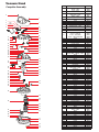
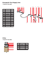
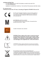
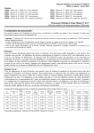
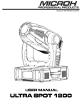
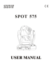
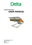
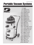
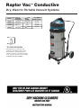
Raptor Vac™ Conductive
Dry, Electric Portable Vacuum Systems
Model
Voltage/
Frequency
Region
(Plug)
Capacity
Gallon (Liter)
61401
120/60 Hz
US/Canada
20 (78)
61403
230/50 Hz
UK
20 (78)
61409
230/50 Hz
CEE7
20 (78)
61413
230/50 Hz
Switzerland
20 (78)
“M” CLASS DRY VACUUM
When employed in accordance with their
intended use, the industrial vacuum cleaners
described in these operating instructions are
suitable for picking up non-flammable, dry dusts.
They correspond to dust class “M” in accordance
to: EN 60335-2-69. By SLG, Germany
Vacuum Head
Complete Assembly
ITEM
DESCRIPTION
P/N
1
Handle – 120 V
Handle – 230 V
Cord – 120 V
Cord – 230 V
Strain Relief – 120 V
Strain Relief – 230 V
Clamp – 120 V
Clamp – 230 V
Screw
Screw
Screw
Cover, Top
Screw
Terminal Board – 120 V
Terminal Board – 230 V
Switch On/Off
Switch Tool Select
Socket – 120 V, US/Canada
Socket – 230 V, UK
Socket – 230 V, CEE7
Socket – 230 V, Switzerland
Screw
Nut
Lamp, Red
Lamp, Orange
Pressure Sensor
Switch Pocket Cover
Filter Bracket
Screw
Guide
Cover Cap
Electric Card - 2 Speed – 120 V
Electric Card - 2 Speed – 230 V
Sleeve
Screw
Cover, Bottom
Washer
Screw
Clamp
Sleeve
Check Valve
Electrovalve – 120 V
Electrovalve – 230 V
Connector
Elbow
Tube (per Meter)
Pressure Reducer
Washer
Elbow
Reducer
Valve
Connector
Air Tank
Safety Valve
Tube
Guide
Gasket
Electronic Card
Bracket
Electronic Card
Screw
Bracket
Screw
Screw
Screw
Heat Sensor
Thermoregulator
Motor Mount
Ring
Cap
Gasket
Motor – 120 V
Motor – 230 V
Gasket
Spacer
Gasket
Filter
Screw
Gasket
Plug
Muffler
Cap
Base
Nipple
Washer
Tube
80460
80464
80440
80485
80495
80486
N/A
80258
80235
80414
80232
80461
80402
80415
80487
80475
80450
80488
80492
80493
80494
80423
80406
80477
80451
80425
80428
80419
80414
80405
80284
80468
80489
80472
80232
80467
80420
80418
80173
80473
80446
80458
80490
80449
80447
80401
80439
80420
80447
80434
80436
80435
80432
80437
80438
80405
80448
80445
80245
80430
80235
80172
80255
80255
80413
80452
80422
80478
80470
80442
80290
80462
80491
80426
80443
80290
80441
80235
80290
80471
80416
80417
80469
80298
80170
80171
2
3
6
4
7
4
230V
3
1
120V
3
2
9
10
5
11
12
19
5
6
7
8
9
10
11
12
13
13
14
15
18
36
8
16
17
26
24
25
48
37
20
45
42
41
40
39
21
23
22
27
51
52
28
50
43
47
44
38
55
29
30
31
57
63
64
62
65
63
64
65
66
67
68
69
70
71
72
73
74
75
46
54
32
33
35
49
58
59
60
61
62
67
68
25
26
27
28
29
30
31
32
33
34
35
36
37
38
39
40
41
42
43
44
45
46
47
48
49
50
51
52
53
54
55
56
57
58
59
60
61
53
56
66
14
15
16
17
18
19
20
21
22
23
24
69
70
71
72
75
74
73
Pneumatic Tool Supply Line
Complete Assembly
3
ITEM
DESCRIPTION
P/N
1
2
3
4
5
6
7
8
9
10
11
12
13
14
15
16
17
18
19
20
Nipple
Fitting
Guide
Bracket
Screw
T Connector
Nipple
Sensor Body
Sensor Plate
Sensor
O-Ring
Screw
Nipple
Washer
Y Connector
Tube (per Meter)
Coupling
Guide
Bracket
Screw
80429
80229
80421
80231
80225
80433
80400
80476
80227
80241
80226
80228
80220
80221
96571
80453
80222
80421
80231
80225
2
5
4 14
17
1
16
Filter
Complete Assembly
1
2
3
4
5
6
7
ITEM
DESCRIPTION
P/N
1
2
3
4
5
6
7
Diffuser
Gasket
Cartridge Support
Filter Support
Screw
Locking Staff
HEPA Filter
80444
80234
80479
80457
80243
80431
80459
7
6
10
11
8
9
12
19 20
13
18
15
Tank /Cart
Complete Assembly
1
2
3
4
5
6
7 8
9 10
15
14
13
12
11
17
16
11
ITEM
1
2
3
4
5
6
7
8
9
10
11
12
13
14
15
16
17
DESCRIPTION
Handle
Hook
Rivet
Seal/Screw
Tank
Screw
Gasket
Gasket
Deflector
Vac Inlet (Orange Button)
Handle
Seal/Screw
Hinge Body
Hinge Clasp
Hinge Knob
Valve
Screw
P/N
80081
80430
80246
80073
80279
80169
80163
80164
80165
80466
80081
80073
80071
80072
80075
80266
80267
ITEM
1
2
3
4
5
6
7
8
9
10
11
DESCRIPTION
Frame
Cap
Retainer
Wheel
Axle Cap
Washer
Nut
Caster
Screw
Foot
Handle Grip
P/N
80269
80270
80062
80061
80063
80080
80079
80078
80225
80271
80272
10
WARNING - An external air supply
source connected to the vacuum
cleaner shall not exceed the Max
Pressure of 150 PSI.
COAXIAL VACUUM HOSE ASSEMBLY – PART NO. 31962
Swivel Cuff
P/N 31907
.43 m Length
1-1/4" (32 mm)
Vac Hose
P/N 31969
Cuff with Air Line Exit
5.1 m Length
1-1/4" (32 mm)
Vac Hose
P/N 31970
P/N
96394
Air Line Assembly - 11" (279 mm) of
Air Line Assembly will Extend Past the Cuff
Dynabrade Male Plug
P/N 95675
Dynabrade Coupler
P/N 94960
1-1/4" DIA. X 20' (32 MM X 6M)
Cuff with Air
Line Exit
.43 m Length
1-1/4" (32 mm)
Vac Hose
P/N 31969
Cuff
P/N 31904
P/N
96394
13-3/4" (350 mm)
of Air Line
Assembly will
Extend Past
the Cuff
Dynabrade Female Plug
P/N 95677
GROUNDING INSTRUCTIONS
This unit must be grounded. If it should malfunction or breakdown,
grounding provides a path of least resistance for electric current to
reduce the risk of electric shock.
WARNING
Where it is critical to avoid shocks or sparks caused by static
electricity, an electrically conductive and grounded air supply
hose must be used.
Grounding by means of a ground wire between both ends of the air supply tubing
passing through vacuum hose is recommended.
A S S E M B LY I N S T R U C T I O N S
Refer to the drawing and parts list for the name and location of parts.
1. While opening the carton, carefully inspect outside of the carton for
any sign of transportation damage, and if so, notify your shipper
immediately.
2. Open carton and remove hoses, hose connectors and other
accessories.
3. Lay carton on its back and wheel the unit out.
4. Remove all packing, release the unit and remove Motorhead/Vacuum
Head Assembly to make sure no packing materials are left inside the
unit.
5. Check to make sure the filter is seated firmly. If not, tighten at base of
filter unit.
7. Remove the vacuum hose assembly. Note that the air supply tube (the
smaller of the two) protrudes at both ends and is longer than the
vacuum hose.
8. Connect quick coupler male end to air outlets located on vacuum
head assembly.
9. Insert vacuum hoses.
10. Connect air supply to air inlet fitting (3/8" NPT female threads)
located at the back side of Motorhead. Air pressure should be
adjusted according to the pressure requirement of the air tools you
are using. Do not exceed 150 PSIG (10.3 kg/cm2). Some pressure
drop is unavoidable between the main air supply and the air tools due
to internal flow resistance in a long air hose.
A 1/2" INTERNAL DIAMETER SUPPLY AIR LINE is recommended.
Set regulator by installing an in-line pressure gage (Part No.
94315) at the inlet of the air tool being used. Run the tool and
adjust regulator such that there is 90 PSIG @ the tool inlet.
The installation of a Dynabrade Filter-Regulator-Lubricator (FRL
Part No. 11411) is highly recommended to protect the unit and
the air tools.
Where it is critical to avoid shocks or sparks caused by static
electricity, an air supply hose which is electrically conductive
and ground must be used.
11. All Dynabrade Vacuum Models come with a sample dust bag. Install
bag inside main body. Make sure that vacuum connection tube
protrudes through the hole in the bag.
12. Order dust bags (Part No. 64682) before you run out of them.
13. Return Motorhead/Vacuum Head Assembly to the unit and lock the
twor rim clamps to secure Motorhead/Vacuum Head Assembly in
position.
14. Connect your Dynabrade air tool or accessory and you are now ready
for working with the Dynabrade Portable Vacuum System.
THIS IS A PRECISION PIECE OF EQUIPMENT designed for dust extraction to keep your ENVIRONMENT
and your REPUTATION “DUST-FREE.” Read operating instructions before using Dynabrade Portable
Vacuum System and be thoroughly conversant with safety precautions in your locality.
O P E R AT I N G I N S T R U C T I O N S
The following items should be well-noted for the effective use of the unit.
1. Always wear safety glasses and any other safety items
required by law.
2. The vacuum system will operate by an on/auto/manual switch
located on the front of the Motorhead/Vacuum Head Assembly.
This switch must be turned on to activate the Motorhead.
3. VACUUM SPEED CONTROL: Unit is equipped with a one tool or
two tool speed setting.
4. ELECTRONIC THERMAL PROTECTION DEVICE: Unit is
equipped with a overload prevention system. If this feature is
activated a 20 MIN. COOL DOWN PERIOD inhibits use. After a
complete 20 min. cool down period has passed the Electronic
Thermal Protection Device will RE-SET automatically and
the unit will be on line ready for use.
5. VISUAL WARNING SIGNAL: Unit is equipped with a visual
warning (yellow) light to indicate when air velocity falls below
20m/s. Turn off vacuum and replace disposable collection bag.
The warning signal will RE-SET automatically and the unit will
be ready for use.
O P E R AT I N G T I P S A N D T R O U B L E S H O O T I N G
Keep machine clean to ensure optimum performance. After each
use, lift off vacuum head and knock dust from filter. After one hour
of continuous use, lift out the Motorhead/Vacuum Head Assembly
and check the amount of dust accumulated in the unit. Remove the
dust bag if necessary and replace with a new one. We recommend
a soft brush to clean the filter. DO NOT USE A BLOW GUN.
Decrease in Vacuum Performance
1. Clean the filter thoroughly and as often as necessary. The
filter used inside is water resistant and washable. To prevent
damage, do not use high pressure or solvent to wash the filter.
2. If the filter (P/N 80459) should become damaged or badly
clogged and cannot be cleaned, replace with a new one.
3. Check all the vacuum lines for blockage or leakage.
Vacuum Stops During Use
1. This vacuum is equipped with a Electronic Thermal Protection
Device. If the vacuum stops and the red indicator light appears
ON, the unit has shut down as a result of increased
temperature. Once the unit has regained a temperature that is
allowable for operation the vacuum will resume operation.
R E M O V A L / I N S TA L L AT I O N O F M O T O R H E A D F R O M M A I N A S S E M B LY
If the filter element becomes clogged or to clean the inner portions
of the drum (canister) the Motorhead Assembly must then be
removed to perform cleaning. When removal becomes necessary
for cleaning or other service, follow the procedures described
below.
Removal
1. Unplug the unit before attempting service or maintenance work.
2. Remove Top Lid by unlatching (2) hinges.
3. Use a conventional vacuum cleaner to clean entire inside of
Motorhead/Vacuum Head Assembly and drum (canister).
Upon completion of the service work, install top lid according to
the following procedure:
Installation
1. Place cleaned unit onto the drum (canister) and latch (2)
hinges to properly attach the lid. Unit is now ready for
operation.
T I LT- N - C L E A N O P E R AT I O N I N S T R U C T I O N
Unit has a Tilt-n-Clean feature to aid in overall functionality of the
work equipment and work environment:
1. Unplug the unit before attempting service or maintenance
work.
2. Unclamp and remove Motorhead/Vacuum Head Assembly.
Drum (canister) is now able to be tilted backwards and emptied.
Dispose of debris properly.
3. Or, Pull side release hinges away from the drum (canister)
and remove the entire drum (canister) from the trolley. With
drum (canister) removed dispose of debris properly.
T E C H N I C A L S P E C I F I C AT I O N S – P O R TA B L E V A C U U M S Y S T E M S
Model No.............................All Models (Reference Pg. 1)
Noise Level ........................ 73,2 dB(A)
Air Pressure........................ 80 to 150 PSIG (5.6 to 10.4 kg/cm2)
Filter.................................... H.E.P.A. (0.3 micron)
Unit Capacity Size .............. 20 gallon/-78 liter
No. of Vacuum Outlets........ 2
No. of Pneumatic Outlets .. 2
Construction ...................... Stainless Steel Drum (Canister)
Remainder: Plastic and Metal Components.
Dust & Debris Collection.... Cloth Bag, H.E.P.A.(0.3 micron).
Standard Accessories ........ 2 Pieces of 1-1/4" I.D. x 20' Long Flexible Vacuum
Hose with Built-In 3/8" I.D. Air Supply Tubing
Standard Vacuum Hose...... (2) 20' x 1-1/4" Light Weight Coaxial Hose
(6M x 32mm)
Vacuum Control.................. One Tool / Two Tool
Cord Set .............................. 27' (8M)
0406
“M” CLASS DRY VACUUM
(MT20)
14HA
DYNABRADE, INC.
www.dynabrade.com
8989 Sheridan Drive • Clarence, NY 14031-1419 • Phone: (716) 631-0100 • Fax: 716-631-2073 • International Fax: 716-631-2524
© DYNABRADE, INC., 2015
ORIGINAL INSTRUCTION
IT IS RECOMMENDED TO KEEP THIS MANUAL ALWAYS ON HAND FOR
FUTURE REFERENCES.
WARNING: PLEASE READ CAREFULLY THE INSTRUCTION MANUAL BEFORE USING.
Dry vacuum cleaner
Certified to vacuum class “M” dusts - According to Regulation EN 60335-2-69 annex AA
the CE mark “European Compliance” means that the product is
in accordance with the essential requirements provided by the
law, concerning safety and public health measures, protection
of the consumer, etc.
M
M FILTRATION: MEDIUM HAZARD
for separating all dusts with all limit values of occupational exposure not less than 0.1 mg/m³
Symbol of hazardous dust collection
WARNING: These symbols will be used to remind the operator
to pay attention to operations that may cause lesions, including death, to the operator or to other people or animals nearby.
Furthermore, the operations indicated by these symbols may
cause damages, even irreparable ones, to the suction device.
ATTENTION: Please read carefully the instruction manual before
using. it is recommended to keep this manual for future references.
Do not dispose of power tools into household waste!
According to the European Directive 2012/19/UE on waste electrical
and electronic equipment (WEEE) and its incorporation into national
law, power tools that are no longer suitable for use must be separately
collected and sent for recovery in an environmental- friendly manner.
INDICATIONS TO BE STRICTLY ADHERED TO
• This vacuum cannot be used by children, by people with reduced physical,
sensorial or mental capacities or without any experience and knowledge,
unless they did not receive instructions relative to the use of the appliance
and are controlled by a person responsible for their safety
• Children should be controlled so that they don’t play with the appliance.
• The packaging components could constitute potential dangers (as for example plastic bags): they must be kept away from children’s reach and from
other people or animal not conscious of their actions.
• To correctly dispose of the packaging follow the local standards in force.
Any different use from that indicated in this manual could constitute a danger,
therefore, it must be avoided.
• WARNING: Operators must be properly trained for using these machines.
• WARNING: Only for indoor application.
• WARNING: This appliance must be stored, taking its weight into consideration, on a solid, steady, safe and not sloping plane, indoor and in moisture
free environments.
• WARNING: This appliance can be used for suction dry only, and it cannot
be stored in the open or under damp conditions.
• WARNING: Do not vacuum liquids.
• WARNING: Don't ever point the suction towards delicate parts of the body –
of people or animals - such as eyes, ears, mouth, etc.
• WARNING: If the appliance is provided with a supplementary socket, do not
exceed the power reported on the socket. Non-observance may cause fires
and damages even lethal to the user.
• WARNING: The appliance is not suitable for areas protected against electrostatic discharges.
• WARNING: Make sure that the power cable is totally unrolled before you
start using the vacuum.
• WARNING: Use only the accessories supplied with the appliance or those specified in the instruction manual. Using other accessories might compromise the operator safety.
• WARNING: Do not leave the unsupervised a working machine. Always remove
the plug from the socket if the appliance is not working, and store it away from the
reach of children or people who are not conscious of their own actions.
• WARNING: When using electric tools do not exceed the power reported on the
additional socket. Make sure that the line voltage of the electric hand tool coincide
with that reported on the label of technical data. Non-observance of this rule may
cause fires and damages even lethal to the user.
• WARNING: This appliance is not suitable to pick up toxic, explosive, flammable or
incandescent substances. The maximum temperature allowed is 40°C / 104°F.
• Every part of the appliance must be correctly assembled before using it. Verify,
furthermore, that the filtering elements have been correctly and efficiently assembled.
• The appliance must be operated, installed, repaired and handled on a steady,
safe and not sloping plane.
• Make sure that the values indicated on the technical data label correspond to
those of the network to which you intend to connect the appliance and that the
socket is compatible with the plug.
• Do not pick up materials that can damage the filtering elements (such as glass,
metal etc.).
•
•
•
•
•
Do not ever pull or lift the appliance through the electrical cable.
Don’ t touch the plug or the appliance with wet hands.
Do not immerse the vacuum into water, neither use water jets to clean it.
Always remove the plug from the socket before performing anymaintenance work.
Regularly control the feeding cable looking for damages, cracks or ageing. Replace the cable if necessary.
• Specialized personnel must always carry out maintenance and repairs; any damaged part must be replaced with original spare parts.
• WARNING: It is forbidden to carry out changes to the appliance. Tampering could
cause fires and damages even lethal to the user and could make warranty no
more effective.
• The manufacturer declines any responsibility for damages caused to people or
things due to non-compliance of these instructions or if the appliance is not properly used. The operator that use the vacuum cleaner equipped with an essential
filter must be an authorized person and must be aware of the risks resulting from
the vacuuming of toxic substances.
WARNING: This vacuum is equipped with a manostat with a control led
that lights when the cartridge filter (essential filter) is clogged and must
be replaced.
Do not clean the essential filter with air.
The essential filter must be disposed of after use. This is necessary in
order not to compromise the efficiency of the filtering system which would
let go unwanted dust particles into the environment.
• To guarantee a safe and sustained functioning of the machine, do periodically the
routine maintenance, checking the integrity of plastic parts and technical issues,
concerning filtrating efficiency and the correct operating of the main control system.
• Regularly control the power cable looking for damages, cracks or ageing. If the
cable is damaged replace it.
• The substitution of the damaged cable must be done by the tech assistance service or by competent authorized personnel with recognized qualification
• When using electrical extension cord, make sure that it is compatible with the
power cable and that it is not in contact with liquids or conductive surfaces
• Check that the machine is equipped with all the safety devices and their efficiency.
• Before sending the vacuum to technical assistance, it must be cleaned outside
and inside the tank, removing the filtering system if contaminated, just to prevent
risks to maintenance men.
• Before any operation prepare all the appropriate measures for one’s personal
safety, for the safety of others and of the surrounding environment (refer to the
safety procedures in the work place).
• All the parts of the device must be deemed to be contaminated when they are removed from the area of use and appropriate action must be taken to prevent dispersal of dust.
• When maintenance or repair operations are carried out, all contaminated elements which cannot be cleaned well must be eliminated.
• These elements must be eliminated in impenetrable bags conforming to the regulations applicable for the elimination of such materials.
• It is necessary to supply a proper exchange of air in the room if the exhaust air of
the device returns into the room. Reference to national regulations is necessary.
• The dusts on the essential filter are or could be toxic, therefore we suggest that
instruments for personal protection be used: use gloves, protective mask for nose
and mouth, protective glasses and a full overall to prevent contaminated dust from
making contact with other parts of the operator’s body.
• Use a container suitable for disposal.
• The advice mentioned is the minimum safety requirement to be adopted. Please
take note of the safety regulations in the work place.
• It is recommended to wait a few minutes (after turning off the vacuum cleaner)
before removing the essential filter so that any contaminated powder be allowed
to settle inside the tank.
•
•
•
•
The dirty essential filter is toxic waste and must be treated as such.
For the disposal thereof please adopt the procedures recommended by
the relevant laws in force applied at the place of use.
It is advisable to immediately place the dirty essential filter, dismantled
from the vacuum cleaner, into the appropriate container for disposal.
The user can clean the machine only with a dry cloth.
NOISE LEVEL: Values measured according to EN 60704 - 1 (1997) / EN 60704
-2 - 1 (2001) rules. Measurement A for the sound pressure level of the machine
is = 73,2 dB (A) Under unfavorable power conditions, the appliance may cause
temporary drops in voltage
VIBRATION: The value of the hand-arm vibration on the suction pipe is less than
2,5m/s² as recommended by ISO 5349-1
MOTOR PERFORMANCES:
Nominal power 1250W max
Maximum vacuum 251 hPa
Maximum air flow 238 m³/h
COMPONENTS AND FEATURES
Description of electro/pneumatic controls
(B) BLACK ELECTRIC SWITCH (I O II)
(select different working modes)
MODE “0”: machine is off
MODE “I”: the motors are working with cyclic cleaning of the cartridge filter
MODE “II”: electro/pneumatic telecontrol system is in automatic mode and the
cleaning of the cartridge filter are working.
Vacuum cleaner engine turns on or off automatically depending on whether or
not the following accessories are on or off:
1the electro-tool connected to the supplementary socket (max W see label
on the plug “S”)
2the air tool connected to the compressed air socket (V1).
To connect the electro tool the maximum power (W max) achievable is printed
on the label placed on socket’s flap.
When the tool is switched off, after about 8’’ the vacuum cleaner motor will
switch off.
IMPORTANT INFORMATION WHEN CONNECTING ELECTRO/PNEUMATIC
TOOLS TO THE VACUUM CLEANER
WARNING: The manufacturer is not responsible for damages to people or
things due to an incorrect or negligent use of the ELECTRIC REMOTE CONTROL DEVICE.
WARNING: THE ADDITIONAL SOCKET IS ALWAYS UNDER POWER WHEN
THE MACHINE PLUG IS CONNECTED TO POWER SUPPLY
WARNING: BEFORE CONNECTING ELECTRICAL OR PENUMATIC TOOLS
TO THE SUCTION MACHINE CHECK THAT THEY ARE SWITCHED OFF
WARNING: BEFORE TURNING THE ELECTRIC SWITCH ON THE VACUUM
MACHINE TO “0“ CHECK THAT THE TOOL IS OFF
WARNING: When using electro-tools, do not exceed the power reported on the
vacuum cleaner additional socket. Check that the electro-tool input voltage corresponds to what is reported on the technical data plate on the vacuum cleaner.
Non-observance of these rules can cause serious accidents and damages to
the user, also leading to death. It is necessary that the vacuum machine is connected to a grounded socket.
WARNING: When pneumatic tools are used do not exceed the woking pressure of 150 PSI (10 atm) – Danger of air hose explosion
When the job is done disconnect the tool from the vacuum machine
WARNING: Changes in the electrical connection of the vacuum cleaner
could cause serious damages, even the death of the operator, and irreparable damages to the vacuum cleaner.
(B1) WHITE SLIDE SWITCH (I II) (optional)
(seleziona le due velocità)
POSIZITION “I”: low speed
1 user – 1 flexible hose
POSIZITION “II”: high speed
2 users – 2 flexible hoses
(U) ORANGE INDICATOR LIGHT
Connected to a pressure switch, when it lights means that the cartridge filter
(essential filter) is clogged and it must be replaced.
(U1) RED INDICATOR LIGHT
It turns on when the thermal protection that stops the motor is activated. The
thermal protection works when the temperature of the air coming out from
the motor is about 85°C. The motor overheating is due to an obstructed filter
cartridge.
CE DICHIARAZIONE DI CONFORMITA’
EC DECLARATION OF CONFORMITY
2006/42/CE - 2004/108/CE - 2011/65/CE
We:
DYNABRADE
8989 Sheridan Drive
Clarence New York 14031-1490
declare under our responsibility that the product to which this declaration relates is
in conformity with the following standards or other normative document(s):
0RGHOV
•
IEC 60335 -1:2010 + A1:2013
SAFETY
•
IEC 60335 - 2 - 69:2012
SAFETY
•
EN 60335-2-69 allegato AA
CLASS DUST
•
IEC 62233: 2008
EMF
•
EN 55014 - 1:2006 + A1:2001 + A2:2008
EMC
•
EN 55014 - 2:1997 + A1:2001 + A2:2008
EMC
•
EN 61000 - 3 - 2: 2006 + A1:2009 + A2:2009
EMC
•
EN 61000 - 3 - 3: 2013
EMC
following the provisions of the Directives: 2006/42/EC (Machinery directive) - 2004/108/EC
(Electromagnetic compability EMC) 2011/65/EC (Directive RoHS II)
Person authorised to compile the technical file
DYNABRADE
8989 Sheridan Drive
Clarence New York 14031-1490
Clarence New York 27/03/2015
Colin F. Brogan