1
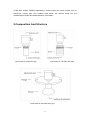
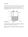
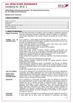
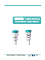
USER MANUAL ULTRASONIC LEVEL METER KAIFENG QINGTIANWEIYE FLOW INSTRUMENT CO.,LTD. No.1 Wangbai Road,Huanglong Industrial Zone,Kaifeng,China TEL:86 - 371 - 27880299 FAX:86 - 371 - 26669963 URL:www.flow-meter.cc INDEX 1.Introduction............................................................................................................................. - 1 1.1 Use.................................................................................................................................. - 1 1.2 Application......................................................................................................................- 2 1.3 Features......................................................................................................................... - 2 1.4 Range............................................................................................................................. - 2 2.Composition and structure................................................................................................. - 3 3.Principle....................................................................................................................................- 4 4.Technical data.........................................................................................................................- 5 4.1 The measuring range...................................................................................................- 5 4.2 The Blanking distance..................................................................................................- 5 4.3 Display resolution......................................................................................................... - 5 4.4 Basic data...................................................................................................................... - 5 4.5 Dimension...................................................................................................................... - 6 4.6 The electronic unit panel layout................................................................................. - 7 4.7 Wiring Diagram............................................................................................................. - 8 5.Level Meter Operation.......................................................................................................... - 8 5.1 Display Method............................................................................................................. - 8 5.2 Key Board...................................................................................................................... - 9 5.3 Two Working Mode...................................................................................................... - 9 5.4 Operation State...........................................................................................................- 11 5.5 Level meter testing.....................................................................................................- 12 6.Instrument installation....................................................................................................... - 13 6.1 General Instruction.....................................................................................................- 13 6.2 Installation Notice....................................................................................................... - 14 7. Seal......................................................................................................................................... - 18 8. Connect the wiring............................................................................................................. - 19 9. Trouble Shooting................................................................................................................ - 19 - 1.Introduction 1.1 Use Liquid level or material level measurement.Liquid level and material level are collectively referred to as level material level are collectively referred to as level. 1.2 Application To ensure that the ultrasonic transmission to the measured ultrasonic liquid level or material surface occasion. Such as: storage tank, chute, pool, Wells, drains, metering box, granary etc. 1.3 Features Integrated design, installed conveniently; Protected in the excessive voltage and current , protected in the thunder and lightning; The big show window of LCD is easy to debug and observe; Over-voltage over-current protection, lightning protection; Advanced since the clamp type terminal, to ensure that wiring never loose; Intellectual signal treatment technology, guarantee that the instrument meets various kinds of operating occasion; All plastic probe, acid and alkali resistant, adapt to bad environment; 1.4 Range The instrument has the following range specifications: Liquid level: 4m,6m,8m,12m,20m,30m; Material level: 3m,5m,7m,10m,15m; Note: 1.The above range level measurement only,Material level measuring the effective range of about 50% of the data,material level measuring proposal chooses four wire or split type level gauge. -1- 2.Cold area outdoor installing applications, should prevent the probe surface frost or freeze.Can choose pipe long material level meter, the internal probe into the container,above model and model selection of the letter L. 2.Composition And Structure Level meter of 4m,6m,8m type Level meter of 12m,20m,30m type Level meter of 20m,30m Horn type -2- 3.Principle The sensor of the meter pulses in the direction of the product surface. There, they are reflected back and received by the sensor.The meter measures the time t between pulse transmission and reception. The meter uses the time t (and the velocity of sound) to calculate the distance D between the sensor membrane and the product surface: D = c •t/2. As the device knows the empty distance H from a user entry, it can calculate the level as follows: L= H – D. B:Blanking distance H: installation height D:distance value F:level span L:level value The ultrasonic velocity in gas is influenced by the gas temperature,So the level meter need to detect the gas temperature at work. So the material level meter need to detect the gas temperature at work,compensation for sound velocity. Blanking distance: Span F may not extend into the blanking distance B. Level echo from the blanking distance cannot be evaluated due to the transient characteristics of the sensor. -3- 4.Technical data 4.1 The measuring range Liquid 4.00m 6.00m 8.00m 12.00m 20.00m 30.00m 4.2 The Blanking distance 4m 6m 8m 12m 20m 30m 0.20m 0.25m 0.30m 0.50m 0.80m 1.2m 4.3 Display resolution 4m 6m 8m 12m 20m 30m 1mm 1mm 1mm 1cm 1cm 1cm 4.4 Basic data Power supply DC24V (±10%) 30mA Display 4 digit LCD Display resolution 0.03% of the actual range Output current 4-20mA Output load 0-500Ω Temperature range -40 ℃~75℃ Pressure range ±0.1MPa (press definitely) Temperature compensation full range of automatic compensation Cable diameter Φ 6 ~ Φ12 mm Single wire diameter Φ0.5 ~ Φ1.78 mm Measuring Cycle 1.5 seconds 8º(3db) for range Plane Type Sensor (4m 6m 8m 12m 20m 30m) 5º(3db) for range Horn Type Sensor (20m,30m) Electronic unit shell material die-casting aluminum with plastic-sprayed surface The sensor material ABS/PVC/PTFE Protect grade IP67 -4- Installation: Thread or Flange or bracket Cable Entry: M20 Parameter set up 3 induction buttons 4.5 Dimension 4m type,6m type,8m type 12m,20m,30m type -5- 20m,30m Horn type 4.6 The Electronic Unit Panel Layout -6- 4.7 Wiring Diagram Note: Power supply for DC24V level meter itself, Please pay attention to the wiring signs.Outer loop should be have current power supply capability of 30mA. 5.Level Meter Operation 5.1 Display Method This level meter has 4 digits LCD display. 5.2 Key Board -7- 5.3 Two Working Mode 5.3.1 The instrument has two working mode: running state and operating state. Press the two keys SEL and MOV to change within two different modes. In running mode, green lamp will keep on lighting. In programming mode, green lamp will flash. 5.3.2 On measuring mode, level meter will carry out normal measuring, at this time, press the SEL key, displayed location value, empty value and temperature will be alternated. 5.3.3 There will be a ▲mark on the right side of LCD screen, which will flash to show that returned wave can be received. The unit of location and empty value are meter(m), the unit for temperature is (℃). 5.3.4 When power this level meter, or return from programming mode, location value will be displayed first. Thing location value Empty value Temperature 5.3.5 Press the SEL key, displayed location value, empty value and temperature will be alternated. -8- 5.3.6 User ought to unlash the keys when press them down. For that, level mete could display alternately. 5.3.7 In running state, press the INC or MOV, this operation is invalid. 5.3.8 Press SEL and MOV at the same time, and then unlash them, this operation could get into operating state. 5.3.9 Press SEL and MOV at a long time, the level meter will be reset. 5.3.10 This level meter will get distance measurement directly. Thing location value is got from the height of installation detract distance measurement . So distance measurement ought to be correct, and the the height of installation ought or set correctly. 5.3.11 Local temperature have much to do with the accuracy of measurement. So the displayed temperature ought to be correct. 5.3.12 No matter which value is showed on the screen, the output of level meter is homologous with distance measurement. Also user could ask the manufacturer to adjust the homologous value of measured distance and 4-20mA. 5.3.13 Installation height ought to be higher or equal to measured distance, if it’s less than measured distance, that there will be a signal flash on the left sight of screen, ting location value and analog value will be changed, the value of measure distance will be changed. 5.4 Operation State 5.4.1 In this state, the level meter will display sorts of parameter, which ought to be set by user. Press SET to choose and parameter will be displayed as follows: Height of installation: this height means the distance from sensor to the bottom of tank. 5.4.2 Output range: It means the max value of measured material, which is homologous with 4-20mA. 5.4.3 Inner password Input the correct values, the instrument enter into the state of internal work parameter Settings.The user does not have to set the secret code values, do not enter into the state of internal work parameter Settings.Press SEL and Leave this parameter,Or at the same time press the SEL, MOV key to exit the parameter setting state. -9- 5.4.4 According to SEL key parameter choice, according to MOV choose one to make it darker, Press INC to modify.After the modification Should a SEL button again,The instrument can store the parameters. 5.4.5 At the same time press the SEL, MOV key and loosening can exit the parameter Settings, and store the set of parameters. 5.4.6 Set the installation height must be accurate, otherwise the level value may be correct,Installation height not less than the range value of material level meter, otherwise the level value remains the same. At the same time according to the MOV, Press the MOV to choose parameters SEL entered the state parameter Settings Press INC., to change the value of the bit Press the SEL store on a parameter, and into the next parameter - 10 - At the same time according to the MOV, SEL exit parameter set state 5.5 Level Meter Testing 5.5.1 This level meter ought to be supplied with supplied with correct power-DC24V. 5.5.2 Let the probe be perpendicular to a wall, and make sure the measuring distance is larger than the blacking distance, and no barriers within the beam angle zone. 5.5.3 Level meter will display HLUE firstly, and then show thing location value. 5.5.4 Turn on the power and after a few seconds the instrument will enter the running mode. And check the level value 、 the empty value and the temperature value in turn through SEL key. 5.5.5 Move the probe slowly , the level value and the empty value should change slowly accordingly. When this level meter is moving in a short distance (within 1 meter), The moving speed ought to be no more than 0.1m/s. There has a preset reactive ambit in this level meter. When target is beyond the ambit, the level meter need about 5s to make a new measuring. Level meter (full scale within 10m) has a reactive ambit ± 0.5m. Level meter (full scale beyond 10m) has a reactive ambit ±1.2m. Because of reactive ambit, if the measuring distance has a sudden change from far to near, an error may come out of the level meter, although the sudden change on distance won’t happen on factual work condition. 5.5.6 Press SEL and MOV keys simultaneously and then enter the operating mode. Advise the installation height value, the displayed level value and empty value should change accordingly. 5.5.7 User could use ammeter to measure 4-20mA output. - 11 - 6.Instrument installation Reasonable instrument installation is the key to its reliable work. Level meter installed on the top of the container,Probe surface vertical point to liquid level. If is airtight container,should be adopted flange installation.Other conditions can use bracket installation. Flange installation should be according to the thread sizes make the flange of the level meter.20m,30m type has directly equipped with the flange. Suggestion: Installation be carried out by trained person in accordance with the manual. 6.1 General Instruction 1. The temperature of the process may not exceed 75℃,and the pressure may not exceed ±0.1 MPa. 2. For exposed or sunny locations a protective hood is recommended. 3.Level meter must be some distance from the tank wall. 4.There's beam angle when Energy transducer radiate ultrasonic pulse. From energy transducer lower edge to measured medium,please avoid A.B obstacle in the radiation region of ultrasonic wave beam.(For example:human ladder;level switch etc). 5.Please make sure ultrasonic beam angle can not intersect with feed stream. 6.Please make sure the max material level can not enter into measuring blind area. 7.Please try to make sure the energy transducer radiate direction vertical to the medium level. 6.2 Installation Notice 6.2.1 Please take some methods to avoid the level meter from sun shading and rain. Please do not install the meter on the top of material infusion entrance. - 12 - 6.2.2 Energy transducer should be vertical to the measuring medium surface Please note meter can not be install in the middle of the tank(to avoid reflection echo) - 13 - 6.2.3 Meter Installation should be avoid A.B obstacle 6.2.4 If install outside or in moist environment,please tighten seal gland of the cable.Also please make the cable as "U" at the cable entrance. - 14 - 6.2.5 If there's mixing in the tank,please install meter far away from the mixer. Please use guide wave tube installation type if there's some foam or wave. 6.2.6 If is closed tank,the flange and connection tube should be follow below: Model Requirement 4m,6m,8m Flange bore size should be bigger than 65mm; Flange connection tube should with smooth inner wall surface, and length shorter than 400mm. 12m Flange bore size should be bigger than 100mm; Flange connection tube should with smooth inner wall surface,and length shorter than 150mm. 20m,30m Flange bore size should be not smaller than 200mm; Flange connection tube length is shorter than 200mm;Sensor should be out from installation mouth. 6.2.7 If there’s big liquid wave fluctuation or there’s float ball or other obstacle may reflect the wave,user can add a plastic tube inside the tank.Plastic tube can make the wave only transmit in the plastic tube and make sure the measurement stability. Plastic tube inner size should be larger than the outer size of sensor,with smooth inner wall surface,straightness,and full-face. Install the plastic tube from the flange mouth to the bottom of the tank. Please open a hole on the top and bottom of the tube to make sure to keep the same level inside and outside the tube. - 15 - 6.2.8 When install to the cold area, should choose the lengthen sensor of the level meter ,make the sensor extend into the container, shun frost and icing. lengthen sensor of the level meter - 16 - 7. Seal After setting parameters and level meter in normal operation,please tighten the cable entrance water-proof gland. The outer end of cable should be down warping to avoid rain water seeping into. 8. Connect the wiring The terminal blocks are all self-tightening ones. Use a straight screwdriver to wire as follow. Please noted the the power supply specification and polarity. Outer ring circuit should with 30mA current power supply capability. - 17 - 9. Trouble Shooting Trouble Reason Solution No display and do not 1.Power supply error. work 2.Wiring error. 1.Check the power supply. 2.Check the wiring. With display but do not 1.The sensor doesn’t aim at the liquid work or the material. 2.The surface has large fluctuations. 3.Level of material is very uneven. 4.Liquid surface with lots of foam. 5.After emptying the tank, the tank bottom is not flat. 6.Over the measuring range. 1.Adjust the sensor and aim at the material. 2.Add a plastic tube to the tank.(refer to installation instruction). 3.Change to level meter with larger range. 4.Change to level meter with larger range or take other measurement method. 5.After infusing liquid or material,the level meter will back to normal work. 6.Change to level meter with larger range. Display unstable or the measured value has a great deviation. Increase the installation height or prevent the level is too high. Change the installation height to a correct value. Make sure the level meter grounding very well to make it with shielding. Change installation location or add a plastic tube.(refer to installation instruction) Change to use plastic flange plate. Use a rubber gasket to make it isolate with the metal. The level enters the blanking distance. The range value is bigger than installation height. There is strong electromagnetic interference. There is obstacle obstruct the ultrasonic wave. Flange plate is metallic not plastic. The sensor emitting surface or side surface contact with the metal. For the tank with 4m,6m,8m tank flange connection tube length should shorter than 400mm. installation mouth or 12m tank flange connection tube length should shorter than 150mm. sensor is in round tube. 20m,30m sensor should out from the installation mouth. - 18 -