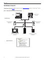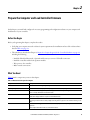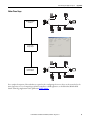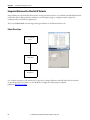
1
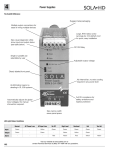
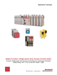
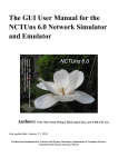
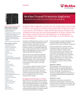
Quick Start
CompactLogix 5370 L1 Controllers
Catalog Numbers 1769-L16ER-BB1B, 1769-L18ER-BB1B, 1769-L18ERM-BB1B
Important User Information
Read this document and the documents listed in the additional resources section about installation, configuration, and
operation of this equipment before you install, configure, operate, or maintain this product. Users are required to
familiarize themselves with installation and wiring instructions in addition to requirements of all applicable codes, laws,
and standards.
Activities including installation, adjustments, putting into service, use, assembly, disassembly, and maintenance are required
to be carried out by suitably trained personnel in accordance with applicable code of practice.
If this equipment is used in a manner not specified by the manufacturer, the protection provided by the equipment may be
impaired.
In no event will Rockwell Automation, Inc. be responsible or liable for indirect or consequential damages resulting from the
use or application of this equipment.
The examples and diagrams in this manual are included solely for illustrative purposes. Because of the many variables and
requirements associated with any particular installation, Rockwell Automation, Inc. cannot assume responsibility or
liability for actual use based on the examples and diagrams.
No patent liability is assumed by Rockwell Automation, Inc. with respect to use of information, circuits, equipment, or
software described in this manual.
Reproduction of the contents of this manual, in whole or in part, without written permission of Rockwell Automation,
Inc., is prohibited.
Throughout this manual, when necessary, we use notes to make you aware of safety considerations.
WARNING: Identifies information about practices or circumstances that can cause an explosion in a hazardous environment,
which may lead to personal injury or death, property damage, or economic loss.
ATTENTION: Identifies information about practices or circumstances that can lead to personal injury or death, property
damage, or economic loss. Attentions help you identify a hazard, avoid a hazard, and recognize the consequence.
IMPORTANT
Identifies information that is critical for successful application and understanding of the product.
Labels may also be on or inside the equipment to provide specific precautions.
SHOCK HAZARD: Labels may be on or inside the equipment, for example, a drive or motor, to alert people that dangerous
voltage may be present.
BURN HAZARD: Labels may be on or inside the equipment, for example, a drive or motor, to alert people that surfaces may
reach dangerous temperatures.
ARC FLASH HAZARD: Labels may be on or inside the equipment, for example, a motor control center, to alert people to
potential Arc Flash. Arc Flash will cause severe injury or death. Wear proper Personal Protective Equipment (PPE). Follow ALL
Regulatory requirements for safe work practices and for Personal Protective Equipment (PPE).
Allen-Bradley, CompactLogix, ControlFLASH, FactoryTalk, FLEX, Integrated Architecture, Kinetix, Logix5000, PanelView, POINT I/O, PowerFlex, Rockwell Software, Rockwell Automation, RSLinx, RSLogix, Stratix
6000, Studio 5000, and Studio 5000 Automation Engineering Design & Environment are trademarks of Rockwell Automation, Inc.
Trademarks not belonging to Rockwell Automation are property of their respective companies.
Where to Start
Follow the path that matches your hardware and network configuration.
Prepare the CompactLogix 5370 L1 Controller
Hardware
Required
page 15
Prepare the Computer and Load Controller
Firmware
Required
page 29
Optional
POINT I/O™
Modules
PowerFlex® 40
Drive
PowerFlex 70
Drive
Kinetix® 350
Drive
PanelView™ Plus
Terminal
For more information on using each optional device,
see Table 1 on page 11.
Configure the EtherNet/IP Network
page 43
Optional
Create a Logix Designer Project
Required
page 47
Rockwell Automation Publication IASIMP-QS024C-EN-P - August 2014
3
Where to Start
How Hardware Is Connected
This quick start, in use with the additional quick starts listed in Table 1 on page 11, describes a CompactLogix™ 5370 L1
control system as shown in Figure 1.
Figure 1 - CompactLogix 5370 L1 Controller in a Star Network Topology
CompactLogix 5370 L1
Control System
Computer
Star Network Topology
Stratix 6000™Switch
PowerFlex 40 Drive with 22COMM-E Adapter
PowerFlex 70 Drive with 20COMM-E Adapter
PanelView Plus Terminal with Built-in
EtherNet/IP Port
Kinetix 350 Drive
Distributed POINT I/O Modules with
1734-AENT Adapter
Application Configuration
4
Rockwell Automation Publication IASIMP-QS024C-EN-P - August 2014
Where to Start
Sample Panel Layout
The sample panel layout shows the orientation of an example CompactLogix 5370 L1 control system using an EtherNet/IP
network.
IMPORTANT
The following graphic is an example panel layout. The layout of CompactLogix 5370 L1 control systems varies by application.
PanelView Plus Terminal
AC Line Filter
Through-the-door
Disconnect
Line Interface Module
E-stop Push Button
PowerFlex 70 Drive
Kinetix 350 Drive
Ethernet Switch
CompactLogix 5370 L1
Control System
PowerFlex 40 Drive Distributed POINT I/O Modules
Rockwell Automation Publication IASIMP-QS024C-EN-P - August 2014
5
Where to Start
Notes:
6
Rockwell Automation Publication IASIMP-QS024C-EN-P - August 2014
Table of Contents
Preface
About the CompactLogix 5370 L1 Controllers . . . . . . . . . . . . . . . . . . . . .
Choose to Integrate Optional Devices . . . . . . . . . . . . . . . . . . . . . . . . . . . . .
Studio 5000 Environment . . . . . . . . . . . . . . . . . . . . . . . . . . . . . . . . . . . . . . . .
Required Software . . . . . . . . . . . . . . . . . . . . . . . . . . . . . . . . . . . . . . . . . . . . . . .
Parts List . . . . . . . . . . . . . . . . . . . . . . . . . . . . . . . . . . . . . . . . . . . . . . . . . . . . . . . .
Additional Resources . . . . . . . . . . . . . . . . . . . . . . . . . . . . . . . . . . . . . . . . . . . . .
10
11
12
12
13
13
Chapter 1
Prepare the CompactLogix 5370 L1
Controller Hardware
What You Need . . . . . . . . . . . . . . . . . . . . . . . . . . . . . . . . . . . . . . . . . . . . . . . . .
Follow These Steps . . . . . . . . . . . . . . . . . . . . . . . . . . . . . . . . . . . . . . . . . . . . . . .
Install the EtherNet/IP Network . . . . . . . . . . . . . . . . . . . . . . . . . . . . . . . . . .
Install the Secure Digital Card . . . . . . . . . . . . . . . . . . . . . . . . . . . . . . . . . . . .
Mount the Controller . . . . . . . . . . . . . . . . . . . . . . . . . . . . . . . . . . . . . . . . . . . .
Install the Local Expansion Module. . . . . . . . . . . . . . . . . . . . . . . . . . . . . . . .
Wire Power to the Controller . . . . . . . . . . . . . . . . . . . . . . . . . . . . . . . . . . . . .
Make Network Connections . . . . . . . . . . . . . . . . . . . . . . . . . . . . . . . . . . . . . .
Make a USB Connection . . . . . . . . . . . . . . . . . . . . . . . . . . . . . . . . . . . . .
Make EtherNet/IP Network Connections. . . . . . . . . . . . . . . . . . . . . .
15
16
17
18
20
21
23
26
26
27
Chapter 2
Prepare the Computer and Load
Controller Firmware
Before You Begin . . . . . . . . . . . . . . . . . . . . . . . . . . . . . . . . . . . . . . . . . . . . . . . .
What You Need . . . . . . . . . . . . . . . . . . . . . . . . . . . . . . . . . . . . . . . . . . . . . . . . .
Follow These Steps . . . . . . . . . . . . . . . . . . . . . . . . . . . . . . . . . . . . . . . . . . . . . . .
Install the Studio 5000 Environment . . . . . . . . . . . . . . . . . . . . . . . . . . . . . .
Automatic Installation of ControlFLASH Software. . . . . . . . . . . . . . . . .
Configure an EtherNet/IP Driver in RSLinx Classic Software . . . . . . .
Set the IP Address for the Computer. . . . . . . . . . . . . . . . . . . . . . . . . . . . . . .
Load the Controller Firmware . . . . . . . . . . . . . . . . . . . . . . . . . . . . . . . . . . . .
Install Additional Software - Optional . . . . . . . . . . . . . . . . . . . . . . . . . . . . .
29
29
30
31
33
33
35
38
41
Chapter 3
Configure the EtherNet/IP Network
Before You Begin . . . . . . . . . . . . . . . . . . . . . . . . . . . . . . . . . . . . . . . . . . . . . . . . 44
What You Need . . . . . . . . . . . . . . . . . . . . . . . . . . . . . . . . . . . . . . . . . . . . . . . . . 44
Assign an IP Address to the Controller over a USB Connection. . . . . . 45
Chapter 4
Create a Logix Designer Project
Before You Begin . . . . . . . . . . . . . . . . . . . . . . . . . . . . . . . . . . . . . . . . . . . . . . . .
What You Need . . . . . . . . . . . . . . . . . . . . . . . . . . . . . . . . . . . . . . . . . . . . . . . . .
Follow These Steps . . . . . . . . . . . . . . . . . . . . . . . . . . . . . . . . . . . . . . . . . . . . . . .
Create a Project . . . . . . . . . . . . . . . . . . . . . . . . . . . . . . . . . . . . . . . . . . . . . . . . . .
Configure the Controller . . . . . . . . . . . . . . . . . . . . . . . . . . . . . . . . . . . . . . . . .
Add a Local Expansion Module . . . . . . . . . . . . . . . . . . . . . . . . . . . . . . . . . . .
Add Ladder Logic to Test the Local Expansion Module . . . . . . . . . . . . .
Rockwell Automation Publication IASIMP-QS024C-EN-P - August 2014
48
48
49
50
51
54
56
7
Table of Contents
Download to the Controller. . . . . . . . . . . . . . . . . . . . . . . . . . . . . . . . . . . . . . . 59
Appendix A
Understanding Other Application
Options
8
DLR Network Topology . . . . . . . . . . . . . . . . . . . . . . . . . . . . . . . . . . . . . . . . . .
Follow These Steps . . . . . . . . . . . . . . . . . . . . . . . . . . . . . . . . . . . . . . . . . . .
Integrated Motion on the EtherNet/IP Network. . . . . . . . . . . . . . . . . . . .
Follow These Steps . . . . . . . . . . . . . . . . . . . . . . . . . . . . . . . . . . . . . . . . . . .
Rockwell Automation Publication IASIMP-QS024C-EN-P - August 2014
62
63
64
64
Preface
This quick start describes how to use CompactLogix 5370 L1 controllers to install a simple CompactLogix 5370 L1
control system and execute a task with a local 1734 POINT I/O output module. The programming examples that are
included are not complex, and offer solutions to verify that devices are functioning and communicating properly.
IMPORTANT
Consider the following points:
• A typical CompactLogix 5370 L1 control system includes more components than listed in this quick start. For example, you can
use 1734 POINT I/O modules over an EtherNet/IP network in a CompactLogix 5370 L1 control system. Other quick starts
describe how to use additional components with your control system.
For a list of quick starts describing how to use other components in Logix5000™ control systems, see Choose to Integrate Optional
Devices on page 11.
• Not all tasks that are described in this quick start are required to complete the final task, that is, use ladder logic to test a
1769-OB16 output module as described beginning on page 47. For example, you do not need a DeviceNet configuration file to
test the module.
We expect that you can attempt to complete additional tasks with your control system by using the publications that are listed on
page 11. When you use those publications, some assumptions are made. For example, if you use a PanelView Plus terminal over an
EtherNet/IP network in a CompactLogix 5370 L3 control system, you must have created a project and assigned an IP address to the
controller.
If you complete all tasks that are described in this quick start, you can easily complete the tasks that are described in the
publications that are listed on page 11.
The following topics are described in this quick start:
• Installing hardware for a basic CompactLogix 5370 L1 control system
• Installing software that is required for the basic CompactLogix 5370 L1 control system
• Configuring an EtherNet/IP network
IMPORTANT
You are not required to install nor configure an EtherNet/IP network to complete the tasks that are described in this quick
start. However, before you can complete the tasks that are described in some of the publications that are listed on page 11,
you must first install an EtherNet/IP network.
For example, Chapter 4, on Create a Logix Designer Project on page 47 describes how to use ladder logic to test a
1734-OB4E output module. The test is completed by using the output module in a local expansion slot in the
CompactLogix 5370 L1 control system and does not require use of a 1783-EMS08T Stratix 6000 managed switch because it
can be done via a USB connection to the controller.
If you use 1734 POINT I/O modules over an EtherNet/IP network in your CompactLogix 5370 L1 control system, as described
in the Logix5000 Control Systems: POINT I/O over an EtherNet/IP Network Quick Start, publication IASIMP-QS027, you must
install and configure an EtherNet/IP network.
Completing all tasks that are described in this quick start can assist you when attempting to complete the tasks in some
other quick starts, such as publication IASIMP-QS027.
• Creating a Studio 5000 Logix Designer™ project
Rockwell Automation Publication IASIMP-QS024C-EN-P - August 2014
9
Preface
About the CompactLogix 5370 L1 Controllers
These CompactLogix 5370 L1 controllers are available:
• 1769-L16ER-BB1B
• 1769-L18ER-BB1B
• 1769-L18ERM-BB1B
IMPORTANT
The tasks that are described in this publication use a 1769-L18ERM-BB1B controller.
These features are available on CompactLogix 5370 L1 controllers:
• Embedded 24V DC input nonisolated power supply
• Secure Digital (SD) card for nonvolatile memory storage
• Network connections:
– USB (single port)
– Support for EtherNet/IP network- Option to use the controller in device-level ring (DLR), linear, and star
topologies on EtherNet/IP networks
• I/O module options:
–
–
–
–
16 embedded 24V DC digital input points
16 embedded 24V DC digital output points
1734 POINT I/O modules as local expansion module
Control of distributed I/O modules over an EtherNet/IP network
• Support for Integrated Motion on the EtherNet/IP network only with the 1769-L18ERM-BB1B controller.
• For more information on using the 1769-L18ERM-BB1B controller in an application that includes Integrated
Motion on the EtherNet/IP network, see Appendix A, Understanding Other Application Options on page 61.
This graphic shows an example CompactLogix 5370 L1 control system.
10
Rockwell Automation Publication IASIMP-QS024C-EN-P - August 2014
Preface
Choose to Integrate Optional Devices
This table describes additional optional devices and their related documentation that you can use in a
CompactLogix 5370 L1 control system on an EtherNet/IP network.
You can view or download publications at http://www.rockwellautomation.com/literature/.
Table 1 - Devices in Logix5000 Control System
Device Type
Product Line(1)
Additional Resource with More Information
Distributed I/O
POINT I/O
Logix5000 Control Systems: Connect POINT I/O Modules over an EtherNet/IP Network Quick Start, publication
IASIMP-QS027
Drives
PowerFlex40
Logix5000 Control Systems: Connect PowerFlex 40 Drives over an EtherNet/IP Network Quick Start, publication
IASIMP-QS029
PowerFlex 70
Logix5000 Control Systems: Connect PowerFlex 70 Drives over an EtherNet/IP Network Quick Start, publication
IASIMP-QS031
Kinetix 350
Logix5000 Control Systems: Connect Kinetix 350 Drives over an EtherNet/IP Network Quick Start, publication
IASIMP-QS032
PanelView Plus
Logix5000 Control Systems: Connect PanelView Plus Terminals over an EtherNet/IP Network Quick Start,
publication IASIMP-QS033
HMI terminals
(1) You can use other I/O modules, drives, and HMI terminals in Logix5000 control systems. These product lines are used for example purposes.
Rockwell Automation Publication IASIMP-QS024C-EN-P - August 2014
11
Preface
Studio 5000 Environment
The Studio 5000 Automation Engineering & Design Environment™ combines engineering and design elements into a
common environment. The first element in the Studio 5000® environment is the Studio 5000 Logix Designer™ application.
The Logix Designer application is the rebranding of RSLogix™ 5000 software and continues to be the product to program
Logix5000™ controllers for discrete, process, batch, motion, safety, and drive-based solutions.
The Studio 5000 environment is the foundation for the future of Rockwell Automation engineering design tools and
capabilities. The environment is the one place for design engineers to develop all elements of their control system.
Required Software
Table 2 lists the software that is used in this quick start. Software requirements are listed at the beginning of each chapter.
Table 2 - Software Used in This Quick Start
Software
Minimum Version
Studio 5000 environment
21.00.00
Yes
Studio 5000 Logix Designer application
21.00.00
Yes
RSLinx® Classic
3.51.00 or later
Yes
ControlFLASH™
Automatically installed with the Studio 5000 environment
Yes
12
Required
Rockwell Automation Publication IASIMP-QS024C-EN-P - August 2014
Preface
Parts List
Table 3 lists the hardware that is used in this quick start. Hardware requirements are listed at the beginning of each chapter.
Table 3 - Parts Used with This Quick Start
Quantity
Cat. No.
Description
1 or more
N/A
DIN rail (steel, not aluminum)
1
One of the following:
• 1769-L16ER-BB1B
• 1769-L18ER-BB1B
• 1769-L18ERM-BB1B
CompactLogix 5370 L1 controller
The tasks that are described in this publication use a 1769-L18ERM-BB1B controller.
1
User Selected, for example1606-XLE120E
Switched-mode power supply
1
1734-OB4E
POINT I/O 8-point 24V DC electronically fused output module
1
1783-EMS08T
Stratix 6000 Ethernet managed switch
2(1)
1585J-M8PBJM-2
RJ45-to-RJ45 patchcord Ethernet cables
(1) One Ethernet cable is required to connect the controller to the Ethernet switch and a second Ethernet cable is required to connect the Ethernet switch to the computer.
Additional Resources
These documents contain additional information concerning related products from Rockwell Automation.
Table 4 - Additional Resources
Resource
Description
CompactLogix 5370 Controllers User Manual, publication 1769- Describes how to design, install, operate, and troubleshoot a CompactLogix 5370 control system.
UM021
ControlFLASH Firmware Upgrade Software User Manual,
publication 1756-UM105
Provides details regarding the installation of ControlFLASH software and execution of firmware upgrades.
Ethernet Design Considerations Reference Manual, publication
ENET-RM002
Describes installing an EtherNet/IP network.
EtherNet/IP Embedded Switch Technology Application Guide,
publication ENET-AP005
Describes using the controller in a DLR network topology.
EtherNet/IP Network Configuration User Manual, publication
ENET-UM001
Describes how to install, configure, and operate EtherNet/IP modules.
Integrated Architecture and CIP Syne Configuration Application
Technique, publication IA-AT003
Describes using the controller in an application that includes Integrated Motion on the EtherNet/IP network.
Integrated Motion on the EtherNet/IP Network Configuration
and Startup User Manual, publication MOTION-UM003
Describes using the controller in an application that includes Integrated Motion on the EtherNet/IP network.
Logix5000 Control Systems: Connect POINT I/O Modules over
Describes basic steps that are required to include distributed POINT I/O modules over an EtherNet/IP network in a
an EtherNet/IP Network Quick Start, publication IASIMP-QS027 Logix5000 control system, including hardware, firmware, and software considerations.
Logix5000 Control Systems: Connect PowerFlex 40 Drives over Describes basic steps that are required to include PowerFlex 40 drives over an EtherNet/IP network in a Logix5000
an EtherNet/IP Network Quick Start, publication IASIMP-QS029 control system, including hardware, firmware, and software considerations.
Logix5000 Control Systems: Connect PowerFlex 70 Drives over Describes basic steps that are required to include PowerFlex 70 drives over an EtherNet/IP network in a Logix5000
an EtherNet/IP Network Quick Start, publication IASIMP-QS031 control system, including hardware, firmware, and software considerations.
Logix5000 Control Systems: Connect Kinetix 350 Drives over an
EtherNet/IP Network Quick Start, publication IASIMP-QS032
Describes basic steps that are required to include Kinetix 350 Multi-axis Servo drives over an EtherNet/IP network in
a Logix5000 control system, including hardware, firmware, and software considerations.
Logix5000 Control Systems: Connect a PanelView Plus Terminal
over an EtherNet/IP Network Quick Start, publication IASIMPQS033
Describes basic steps that are required to include PanelView Plus terminals over an EtherNet/IP network in a
Logix5000 control system, including hardware, firmware, and software considerations.
Rockwell Automation Publication IASIMP-QS024C-EN-P - August 2014
13
Preface
Table 4 - Additional Resources
Resource
Description
Stratix 6000 Ethernet Managed Switches Installation
Instructions, publication 1783-IN004
Describes installing an EtherNet/IP network.
Stratix 6000 Ethernet Managed Switch User Manual,
publication 1783-UM001
Describes installing an EtherNet/IP network
EtherNet/IP Media Planning and Installation Manual, ODVA
publication
Click here to access the publication
Describes how to design and install an EtherNet/IP network.
Industrial Automation Wiring and Grounding Guidelines,
publication 1770-4.1
Provides general guidelines for installing a Rockwell Automation® industrial system.
Product Certifications website, http://www.ab.com
Provides declarations of conformity, certificates, and other certification details.
You can view or download publications at http://www.rockwellautomation.com/literature/. To order paper copies of
technical documentation, contact your local Allen-Bradley distributor or Rockwell Automation sales representative.
14
Rockwell Automation Publication IASIMP-QS024C-EN-P - August 2014
Chapter
1
Prepare the CompactLogix 5370 L1 Controller Hardware
This chapter describes how to install the hardware that is needed for your CompactLogix 5370 L1 control system.
What You Need
Table 5 lists the hardware components that are used in this chapter.
Table 5 - Parts Used with This Quick Start
Quantity
Cat. No.
Description
1 or more
N/A
DIN rail (steel, not aluminum)
1
One of the following:
• 1769-L16ER-BB1B
• 1769-L18ER-BB1B
• 1769-L18ERM-BB1B
CompactLogix 5370 L1 controller
The tasks that are described in this publication use a 1769-L18ERM-BB1B controller.
1
User Selectable, for example 1606XLE120E
NEC Class 2/SELV switched-mode power supply
1
1734-OB4E
POINT I/O 8-point 24V DC electronically fused output module
1
1783-EMS08T
Stratix 6000 Ethernet managed switch
2(1)
1585J-M8PBJM-2
RJ45-to-RJ45 patchcord Ethernet cables
(1) One Ethernet cable is required to connect the controller to the Ethernet switch and a second Ethernet cable is required to connect the Ethernet switch to the computer.
Rockwell Automation Publication IASIMP-QS024C-EN-P - August 2014
15
Chapter 1
Prepare the CompactLogix 5370 L1 Controller Hardware
Follow These Steps
Install the
EtherNet/IP
Network
page 17
Install the Secure
Digital Card
page 18
Mount the
Controller
page 20
Install the Local
Expansion Module
Wire Power to
the Controller
Make Network
Connections
16
page 21
page 23
page 26
Rockwell Automation Publication IASIMP-QS024C-EN-P - August 2014
Prepare the CompactLogix 5370 L1 Controller Hardware
Chapter 1
Install the EtherNet/IP Network
You are not required to install an EtherNet/IP network to complete the tasks that are described in this quick start. You can
complete the tasks via a USB connection to the CompactLogix 5370 L1 controller. However, we recommend that you
install an EtherNet/IP network.
You can complete some tasks that are described in the publications that are listed on page 11. If you install an EtherNet/IP
network when using this quick start, you can complete the tasks that are described in the publications that are listed on
page 11 more easily.
For information on installing an EtherNet/IP network, see the publications that are listed in the following table.
Network
Publication Title
Publication Number
EtherNet/IP
EtherNet/IP Media Planning and Installation Manual
Publication that is maintained and made available by
ODVA. Click here to access the publication.
Ethernet Design Considerations Reference Manual
ENET-RM002
Stratix 6000 Ethernet Managed Switches Installation Instructions
1783-IN004
Stratix 6000 Ethernet Managed Switch User Manual
1783-UM001
The publications that are listed previously describe how to install the communication network and not how to connect
your controller to the network. Make Network Connections on page 26 describes how to connect your controller to the
network.
Rockwell Automation Publication IASIMP-QS024C-EN-P - August 2014
17
Chapter 1
Prepare the CompactLogix 5370 L1 Controller Hardware
Install the Secure Digital Card
The SD card provides nonvolatile storage for the CompactLogix 5370 L1 controller. You can store Logix Designer projects
to an SD card or load a Logix Designer project from an SD card.
The following SD cards are available for use with your CompactLogix 5370 L1 controller:
• 1784-SD1 card - 1 GB of memory
• 1784-SD2 card - 2 GB of memory
The CompactLogix 5370 L1 controllers ship from the factory with the 1784-SD1 SD card installed.
Complete these steps to reinstall an SD card that has been removed from the controller back into the controller or if
installing a new SD card into the controller.
WARNING: When you insert or remove the SD card while power is on, an electrical arc can occur. This could cause an explosion in
hazardous location installations.
Be sure that power is removed or the area is nonhazardous before proceeding.
1. Verify that the SD card is locked or unlocked according to your preference.
Consider these points when deciding to lock
the card before installation:
• If the card is unlocked, the controller can
write data to it or read data from it.
• If the card is locked, the controller can
only read data from it.
18
Unlocked
Rockwell Automation Publication IASIMP-QS024C-EN-P - August 2014
Locked
Prepare the CompactLogix 5370 L1 Controller Hardware
Chapter 1
2. Open the door for the SD card.
3. Insert the SD card into the SD card slot.
You can install the SD card in only one
orientation. The beveled corner is at the top.
An orientation logo is printed on the card.
If you feel resistance when inserting the SD
card, pull it out and change the orientation.
4. Gently press the card until it clicks into
place.
5. Close the SD card door.
Rockwell Automation Publication IASIMP-QS024C-EN-P - August 2014
19
Chapter 1
Prepare the CompactLogix 5370 L1 Controller Hardware
Mount the Controller
1. Pull out the locking tabs.
2. Slide the controller into position on the
DIN rail and push the locking tabs in.
3. Make sure the protective covering on the
right side of the controller is removed.
The protective covering must be removed to
install a local expansion module, as
described beginning on page 21.
20
Rockwell Automation Publication IASIMP-QS024C-EN-P - August 2014
Prepare the CompactLogix 5370 L1 Controller Hardware
Chapter 1
Install the Local Expansion Module
This quick start uses a 1734-OB4E POINT I/O output module in a local expansion module slot.
1. Make sure the DIN rail locking screw in the mounting base, for example, the 1734-TB mounting base, is in the
vertical position.
2. Align the tongue and groove slots of the
mounting base to the slots on the right side
of the controller and push it back until it
seats on the DIN rail.
3. Use a small-bladed screwdriver to rotate the
DIN rail locking screw to a horizontal
position, locking the mounting base in
place.
4. Set the key position on the mounting base
before installing the 1734-OB4E module.
This example shows position 1.
5. Make sure the output module’s key position
matches the position that is used on the
mounting base. Pull the key out from the
output module to reposition it if necessary.
6. Insert the module straight into the
mounting base and press to secure.
Rockwell Automation Publication IASIMP-QS024C-EN-P - August 2014
21
Chapter 1
Prepare the CompactLogix 5370 L1 Controller Hardware
7. Insert the RTB end opposite the handle into
the base unit.
The end has a curved section that engages
with the mounting base.
8. Rotate the terminal block into the
mounting base to lock it in place.
9. Snap the RTB handle into place on the
module.
10. Connect an end cap to the right side of the
module.
22
Rockwell Automation Publication IASIMP-QS024C-EN-P - August 2014
Prepare the CompactLogix 5370 L1 Controller Hardware
Chapter 1
Wire Power to the Controller
This quick start uses a 1606-XLE120E NEC Class 2, switched-mode power supply to power the CompactLogix 5370 L1
controller. The controller used in this quick start is a CompactLogix 5370 L1 series B controller. Further wiring
information for the CompactLogix 5370 L1 series A controller can be found in the CompactLogix 5370 Controllers User
Manual, publication 1769-UM021.
IMPORTANT
This section describes how to wire power to the controller. The controller is grounded by its connection to the DIN rail.
1. Verify that input power to the external power supply is turned off.
2. Mount the power supply on the DIN rail.
3. Wire input power to the power supply by
using the following terminals:
•
(ground)
• L2 (neutral)
• L1 (line)
4. Connect a wire to the 24V DC+ terminal
on the top of the power supply.
5. Loosen the screws securing the removable
connector to the CompactLogix 5370 L1
controller and pull the connector off of the
controller.
Rockwell Automation Publication IASIMP-QS024C-EN-P - August 2014
23
Chapter 1
Prepare the CompactLogix 5370 L1 Controller Hardware
6. Open the top terminal on the removable
connector.
7. Insert the wire that is connected to the
24V DC+ terminal on the external power
supply to the VDC + terminal on the
removable connector and close the terminal.
8. Connect a wire to a 24V DC- terminal on
the power supply.
9. Connect the other end of the wire to the
VDC - terminal on the removable
connector by repeating steps 6 and 7.
10. Plug the removable connector into the
controller.
24
Rockwell Automation Publication IASIMP-QS024C-EN-P - August 2014
Prepare the CompactLogix 5370 L1 Controller Hardware
Chapter 1
11. Secure the removable connector in place.
This graphic shows the 1606-XLP50E
switched-mode power supply that is
connected to the CompactLogix 5370 L1
controller.
12. Turn on incoming power to the external
power supply.
IMPORTANT
You wire only the VDC+ and VDC- terminals on the CompactLogix 5370 L1 controller’s embedded power supply to
complete the tasks in this quick start.
In real-world applications, you can have additional considerations that are related to connected power in an application,
such as connecting power to multiple controllers or connecting power to input and output devices that are connected to
the controller’s embedded I/O modules and local expansion modules via the FP+, and FP- terminals on the removable
terminal.
For more information on connecting power to the CompactLogix 5370 L1 control system, see the CompactLogix 5370
Controllers User Manual, publication 1769-UM021.
Rockwell Automation Publication IASIMP-QS024C-EN-P - August 2014
25
Chapter 1
Prepare the CompactLogix 5370 L1 Controller Hardware
Make Network Connections
You can make these connections to a CompactLogix 5370 L1 controller:
• Make a USB Connection
• Make EtherNet/IP Network Connections
IMPORTANT
This section describes the methods of connecting your computer to your CompactLogix 5370 L1 controller. This quick start was
written under the assumption that you have installed an EtherNet/IP network.
Make a USB Connection
The controller has a USB port that uses a Type B receptacle. The port is USB 2.0-compatible and operates at 12 Mbps.
Use a USB cable to connect your computer to the USB port. With this connection, you can upgrade firmware and
download programs to the controller directly from your computer.
ATTENTION: The USB port is intended only for temporary local programming purposes and not intended for permanent
connection.
The USB cable is not to exceed 3.0 m (9.84 ft) and must not contain hubs.
WARNING: Do not use the USB port in hazardous locations.
1. Plug one end of the USB cable into your CompactLogix 5370 L1 controller.
2. Plug the other end of the USB cable into
your computer.
26
Rockwell Automation Publication IASIMP-QS024C-EN-P - August 2014
Prepare the CompactLogix 5370 L1 Controller Hardware
Chapter 1
Make EtherNet/IP Network Connections
This section assumes that you installed an EtherNet/IP network as described on page 17 and the network includes a
1783-EMS08T Stratix 6000 Ethernet managed switch.
1. Plug a 1585J-M4TBJM-1, Ethernet cable
(straight-through) into a port on the Stratix
6000 switch.
2. Plug the other end of the Ethernet cable into
one of the Ethernet ports on the bottom of
the controller.
Set the Network IP Address
Once you connect the CompactLogix 5370 L1
controller to an EtherNet/IP network, you must
assign the controller a unique IP address. For information about how to set the network IP address for your controller, see
Chapter 3, Configure the EtherNet/IP Network on page 43.
Rockwell Automation Publication IASIMP-QS024C-EN-P - August 2014
27
Chapter 1
Prepare the CompactLogix 5370 L1 Controller Hardware
Notes:
28
Rockwell Automation Publication IASIMP-QS024C-EN-P - August 2014
Chapter
2
Prepare the Computer and Load Controller Firmware
In this chapter, you install and configure the necessary programming and configuration software on your computer and
load firmware on your controller.
Before You Begin
Before you begin using this chapter, complete these tasks:
• Verify that your computer meets the software’s system requirements for installation and use of the software that is
listed in Table 2 on page 12.
• The tasks that are described in Chapter 1, Prepare the CompactLogix 5370 L1 Controller Hardware on page 15,
including the following:
–
–
–
–
Install the EtherNet/IP network - Optional task because you can use a USB cable connection.
Install the controller and the local expansion module.
Wire power to the controller.
Make network connections.
What You Need
Table 6 lists the components you use in this chapter.
Table 6 - What You Need to Prepare the Computer
Component
Description
Studio 5000 environment
Environment that combines engineering and design elements into a common environment.
Logix Designer application
Software that is used to create a project the CompactLogix 5370 L3 controller uses in your application.
RSLinx Classic software
Communication server that supports multiple software applications simultaneously, establishing communication between
devices on many Rockwell Automation industrial networks.
IP address
A number in the form xxx.xxx.xxx.xxx where each xxx is a number from 000…254.
The IP address uniquely identifies the computer on the EtherNet/IP network.
Subnet Mask
Extension of the IP address that lets a site use one network ID for multiple physical networks.
If you change the subnet mask of an already-configured controller, you must cycle power to the controller for the change to take
effect.
ControlFLASH software
Software that is used to upgrade the firmware on certain Allen-Bradley® products in a CompactLogix 5370 L1 controller
application.
Automatically installed with the Studio 5000 environment installation.
Rockwell Automation Publication IASIMP-QS024C-EN-P - August 2014
29
Chapter 2
Prepare the Computer and Load Controller Firmware
Follow These Steps
Install the Studio 5000
Environment
page 31
Configure an EtherNet/IP
Driver in RSLinx Classic
Software
page 33
Set the IP Address for the
Computer
page 35
Load the Controller
Firmware
page 38
Install Additional
Software - Optional
page 41
30
Rockwell Automation Publication IASIMP-QS024C-EN-P - August 2014
Prepare the Computer and Load Controller Firmware
Chapter 2
Install the Studio 5000 Environment
The Studio 5000 environment installation process is configured so that, among other software applications, RSLinx Classic
software, version 3.51.00, is automatically installed.
The automatic installation option is enabled by default. You can change the installation setting and install RSLinx Classic
software separately. We strongly recommend that you use the installation process default settings that are described in this
chapter.
IMPORTANT
The steps in this section are based on a version 21.00.00 Studio 5000 environment installation. The steps necessary for your
installation may vary.
1. Start the installation.
You can load the software from a CD or web download.
2. Choose a language, enter the required
information, and click Next.
3. Use the default selections and click Install.
4. Read the license agreement carefully.
Rockwell Automation Publication IASIMP-QS024C-EN-P - August 2014
31
Chapter 2
Prepare the Computer and Load Controller Firmware
5. Click Accept All.
The installation process begins.
When installation is complete, your computer has
the software necessary required to complete the
tasks that are described in this publication.
Among other software, your computer has the
following:
• Studio 5000 environment, version 21.00.00
or later
• RSLinx Classic software, version 3.51.00 or
later
You are prompted to activate the software. For more
information on software activation, see the following:
• Rockwell Automation Technical Support Software Activations site
http://www.rockwellautomation.com/rockwellautomation/support/activations.html
32
Rockwell Automation Publication IASIMP-QS024C-EN-P - August 2014
Prepare the Computer and Load Controller Firmware
Chapter 2
Automatic Installation of ControlFLASH Software
ControlFLASH software is used to upgrade a CompactLogix 5370 L1 controller’s firmware revision. ControlFLASH
software is automatically installed when you install the Studio 5000 environment.
For more information on loading firmware on your controller, see Load the Controller Firmware on page 38.
Configure an EtherNet/IP Driver in RSLinx Classic Software
1. Start the software.
2. From the Communications pull-down
menu, choose Configure Drivers.
The Configure Drivers dialog box appears.
3. From the Available Driver Types menu,
choose EtherNet/IP Driver or Ethernet
devices and click Add New.
We recommend that you use EtherNet/IP
Driver.
Rockwell Automation Publication IASIMP-QS024C-EN-P - August 2014
33
Chapter 2
Prepare the Computer and Load Controller Firmware
The Add New RSLinx Driver dialog box
appears.
4. Click OK to keep the default name.
A Configure driver:AB_ETHxxx dialog
box appears. The full name of the dialog box
varies by what driver type was chosen in step
3.
This example uses the EtherNet/IP Driver; the driver name is AB_ETHIP-1.
5. Select an Ethernet card and click OK.
This new driver is available.
6. Verify that the driver’s Status is Running and
click Close.
34
Rockwell Automation Publication IASIMP-QS024C-EN-P - August 2014
Prepare the Computer and Load Controller Firmware
Chapter 2
Set the IP Address for the Computer
Your computer requires an Internet Protocol (IP) address to operate on an EtherNet/IP network. The IP address uniquely
identifies the controller and is in the form xxx.xxx.xxx.xxx where each xxx is a number from 000…254 with some
exceptions for reserved values.
A computer’s IP address can be set automatically or manually. The manual option is typically used with isolated networks.
This section describes how to set the IP address manually.
For more information on setting an IP address for your CompactLogix 5370 L1 controller, see the CompactLogix 5370
Controllers User Manual, publication 1769-UM021.
1. On your desktop, right-click Network and
choose Properties.
2. Click adapter settings.
Rockwell Automation Publication IASIMP-QS024C-EN-P - August 2014
35
Chapter 2
Prepare the Computer and Load Controller Firmware
3. Right-click Local Area Connection and
choose Properties.
4. On the Networking tab, choose Internet
Protocol Version 4 (TCP/IPv4) and click
Properties.
36
Rockwell Automation Publication IASIMP-QS024C-EN-P - August 2014
Prepare the Computer and Load Controller Firmware
Chapter 2
5. Select Use the following IP address and enter
an IP address and Subnet mask for your
computer.
6. Record the IP address and subnet mask.
7. Click OK.
8. Close the Local Area Connection Properties
dialog box.
Rockwell Automation Publication IASIMP-QS024C-EN-P - August 2014
37
Chapter 2
Prepare the Computer and Load Controller Firmware
Load the Controller Firmware
IMPORTANT
This section assumes that you downloaded the controller firmware from the Rockwell Automation technical support website
to install on your CompactLogix 5370 L1 controller. If not, download the firmware before following the steps in this section.
The firmware is available with Logix Designer application or you can download it from the support website.
Go to http://www.rockwellautomation.com/support/.
This section describes how to load firmware on your CompactLogix 5370 L1 controller before setting an IP address for the
controller. In this case, you must connect from your workstation to the controller over the USB port.
With this quick start, you must use RSLinx Classic software, version 3.51.00 or later with CompactLogix 5370 L1 controllers.
When the software is installed, a USB driver is automatically installed. When your computer is connected to the
CompactLogix 5370 L1 controller over a USB connection, the controller appears in the RSWho window whenever you perform
a Browse.
1. Verify that the SD card in the controller is unlocked.
2. Connect to the controller via the USB port as described in Make a USB Connection on page 26.
The controller is powered on. If it is not, turn on power to the controller.
3. Start the ControlFLASH software.
4. Select the directory that you want to use.
38
Rockwell Automation Publication IASIMP-QS024C-EN-P - August 2014
Prepare the Computer and Load Controller Firmware
Chapter 2
5. Click Next.
6. Select the controller catalog number and
click Next.
Rockwell Automation Publication IASIMP-QS024C-EN-P - August 2014
39
Chapter 2
Prepare the Computer and Load Controller Firmware
7. Expand the USB driver, and select your
controller.
8. Click OK.
9. If it’s not in the position, move the mode
switch on the controller to the REM
position.
RUN
REM
PROG
10. Choose the desired firmware revision and
click Next.
TIP
40
Consider the following:
• If the Current Revision matches
the firmware revision that is
shown in the box below it, click
Cancel. You are finished with
this task.
• This example uses firmware
revision 21.011.49. Your
firmware revision is another
number.
You can access the latest firmware
revision at the Rockwell
Automation Technical Support
webpage.
Rockwell Automation Publication IASIMP-QS024C-EN-P - August 2014
Prepare the Computer and Load Controller Firmware
Chapter 2
11. To start the firmware update, click Finish
and click Yes.
Before the firmware upgrade begins, you see
the following dialog box. Take the required
action for your application. In this example,
the upgrade continues when OK is clicked.
This can take a few minutes to complete.
When the update completes, the status box
informs you that the update was successful.
12. In the Update Status dialog box, Click OK.
Install Additional Software - Optional
Depending on your application, you can install additional software.
For example, if you are integrating a PanelView Plus terminal into your system, you must install the following:
• RSLinx Enterprise software
IMPORTANT
You must install this software before you install any other additional software.
• FactoryTalk® View Machine Edition software
Rockwell Automation Publication IASIMP-QS024C-EN-P - August 2014
41
Chapter 2
Prepare the Computer and Load Controller Firmware
Notes:
42
Rockwell Automation Publication IASIMP-QS024C-EN-P - August 2014
Chapter
3
Configure the EtherNet/IP Network
In this chapter, you assign an IP address to your CompactLogix 5370 L1 controller.
This quick start does not describe how to use other devices on the EtherNet/IP network. It is common to use other devices
on an EtherNet/IP network in a CompactLogix 5370 L1 control system. If you were to do so, for example, use a PanelView
Plus terminal on an EtherNet/IP network, you must assign an IP address to those devices.
IMPORTANT
Not all tasks that are described in this quick start are required to complete the final task, that is, use ladder logic to test a
1734-OB4E output module as described beginning on page 47. For example, you do not need to install an
EtherNet/IP network to connect to a CompactLogix 5370 L3 controller because you can do so over a USB cable.
We expect that you can attempt to complete additional tasks with your control system by using the publications that are listed on
page 11 relating to using a component over an EtherNet/IP network in a Logix5000 control system. When you use those
publications, some assumptions are made. For example, if you use POINT I/O modules over an EtherNet/IP network in a
CompactLogix 5370 L1 control system, you must have created a Logix Designer project and have an IP address that is assigned to
the controller.
If you complete all tasks that are described in this chapter, you can easily complete the tasks that are described in the publications
that are listed on page 11 related to using an EtherNet/IP network.
Rockwell Automation Publication IASIMP-QS024C-EN-P - August 2014
43
Chapter 3
Configure the EtherNet/IP Network
Before You Begin
Before you begin using this chapter, complete these tasks:
• The tasks that are described in Chapter 1, Prepare the CompactLogix 5370 L1 Controller Hardware on page 15,
including the following:
–
–
–
–
Install the EtherNet/IP network.
Mount the controller and install the local expansion module.
Wire power to the controller.
Make network connection.
IMPORTANT
If you connect all devices, including the computer, through an Ethernet switch, you can create an isolated network. This
chapter assumes you are using an isolated network. If you are not, contact your network administrator to obtain IP
addresses.
• The tasks that are described in Chapter 2, Prepare the Computer and Load Controller Firmware on page 29,
including the following:
– Install the Studio 5000 environment and RSLinx Classic software.
Logix Designer application is installed when you install the Studio 5000 environment.
– Configure an EtherNet/IP driver in RSLinx Classic software.
– Set the IP address for the computer.
– Load firmware on the controller.
• Verify that power is applied to all devices.
What You Need
Table 7 lists the software components you use in this chapter.
Table 7 - What You Need to Configure the EtherNet/IP Network
Component
Description
Studio 5000 environment
Environment that combines engineering and design elements into a common environment.
Logix Designer application
Software that is used to create a project the CompactLogix 5370 L1 controller use in your application.
RSLinx Classic software
Communication server that supports multiple software applications simultaneously, establishing communication between
devices on many Rockwell Automation industrial networks.
IP address
A number in the form xxx.xxx.xxx.xxx where each xxx is a number from 000…254.
The IP address uniquely identifies the controller on the EtherNet/IP network.
Subnet mask
Extension of the IP address that lets a site use one network ID for multiple physical networks.
If you change the subnet mask of a configured controller, you must cycle power to the controller for the change to take effect.
44
Rockwell Automation Publication IASIMP-QS024C-EN-P - August 2014
Configure the EtherNet/IP Network
Chapter 3
Assign an IP Address to the Controller over a USB Connection
At initial powerup, the CompactLogix 5370 L1 controller does not have an IP address. Use RSLinx Classic software over a
USB connection to assign an IP address. The following steps work only if the computer with RSLinx Classic software is
connected to the controller via a USB connection.
IMPORTANT
There are other methods to assign an IP address to the controller, such as using the BOOTP/DHCP utility. This section is only one
example of how to assign the IP address to the controller.
For more information on the methods of assign an IP address to the CompactLogix 5370 L1 controller, see the CompactLogix 5370
Controllers User Manual, publication 1769-UM021.
1. Verify that your computer is connected to the USB port on the front of the controller.
2. From the Communications menu, choose
RSWho.
The RSWho dialog box appears.
3. Navigate to the USB connection.
4. Right-click the controller and choose Module
Configuration.
The Module Configuration dialog
box appears.
Rockwell Automation Publication IASIMP-QS024C-EN-P - August 2014
45
Chapter 3
Configure the EtherNet/IP Network
5. Click the Port Configuration tab.
6. For Network Configuration Type, click Static
to assign this configuration to the port.
IMPORTANT
The controller’s default
configuration is Dynamic. When
the controller is configured for
Dynamic, on a power cycle, it
clears the current IP address and
resumes sending BOOTP requests.
7. Enter the IP address and Network Mask for
the controller.
8. Enter other network parameters, if necessary.
9. Click OK.
10. In the ControlLogix Gateway Tool dialog
box, click Yes.
For more information on setting the network IP
address, see EtherNet/IP Network Configuration
User Manual, publication ENET-UM001.
46
Rockwell Automation Publication IASIMP-QS024C-EN-P - August 2014
Chapter
4
Create a Logix Designer Project
In this chapter, you create a Logix Designer project. In the project, you use ladder logic to create a push button that controls
a light on a digital output module.
You learn how to complete the following tasks:
• Create a Logix Designer project.
• Configure your 1769-L18ERM-BB1B controller.
• Add a local expansion module to the project.
• Add ladder logic to the project to test the local expansion module.
• Download the project to the controller.
IMPORTANT
You must use Logix Designer application with this quick start. The tasks that are described in this chapter are described with the
intention that you can reuse the project to complete the tasks that are described in publications listed on page 11.
Because you are likely to use other devices in your CompactLogix 5370 L1 control system, you can use the project that is created in
this chapter to complete the tasks that are described in the publications that are listed on page 11.
Rockwell Automation Publication IASIMP-QS024C-EN-P - August 2014
47
Chapter 4
Create a Logix Designer Project
Before You Begin
Before you begin, complete these tasks:
• The tasks that are described in Chapter 1, Prepare the CompactLogix 5370 L1 Controller Hardware on page 15,
including the following:
–
–
–
–
Install the EtherNet/IP network.
Install the controller and the local expansion module.
Wire power to the controller.
Make network connections.
• The tasks that are described in Chapter 2, Prepare the Computer and Load Controller Firmware on page 29,
including the following:
– Install the Studio 5000 environment and RSLinx Classic software.
Logix Designer application is installed when you install the Studio 5000 environment.
– Configure an EtherNet/IP driver in RSLinx Classic software.
– Set the IP address for the computer.
– Load firmware on the controller.
• Set the IP address for the controller as described in Chapter 3 on page 43.
• Verify that all devices are powered.
What You Need
You need Logix Designer application to complete the tasks in this chapter.
48
Rockwell Automation Publication IASIMP-QS024C-EN-P - August 2014
Create a Logix Designer Project
Chapter 4
Follow These Steps
Create a Project
page 50
Configure the Controller
page 51
Add a Local
Expansion Module
page 54
Add Ladder Logic to Test
the Local Expansion
Module
page 56
Download to the
Controller
page 59
Rockwell Automation Publication IASIMP-QS024C-EN-P - August 2014
49
Chapter 4
Create a Logix Designer Project
Create a Project
1. Start the application.
2. Click New Project.
The New Controller dialog box appears.
3. Choose your controller and name the
project.
4. Click Next.
50
Rockwell Automation Publication IASIMP-QS024C-EN-P - August 2014
Create a Logix Designer Project
Chapter 4
5. Set Expansion I/O to a number that
matches the number of 1734 POINT I/O
modules that are physically installed in the
system.
In this case, the value is 1 Module.
6. Click Finish.
Configure the Controller
1. Verify that the mode switch on the
controller is in the REM position.
RUN
REM
PROG
2. Click the Who Active icon.
Rockwell Automation Publication IASIMP-QS024C-EN-P - August 2014
51
Chapter 4
Create a Logix Designer Project
3. In the Who Active dialog box, expand the path to the controller and select it.
4. Click Set Project Path.
By clicking this button, you set the path and
do not have to browse to the controller each
time you use an option in the Who Active
dialog box.
5. Click Go Online.
You must be online to set the controller’s IP
address in the Logix Designer project.
6. Click Download twice on successive dialog
boxes.
7. Change the controller mode to Remote
Run.
8. Click Yes at the dialog box.
9. Expand the I/O Configuration tree.
10. Right-click the controller and
choose Properties.
52
Rockwell Automation Publication IASIMP-QS024C-EN-P - August 2014
Create a Logix Designer Project
Chapter 4
11. Use the tabs on the Controller Properties
dialog box to configure the controller.
The IP address is set on the Internet
Protocol tab.
IMPORTANT
Make sure you set an IP Address
and Subnet Mask that matches
the values set in Set the IP
Address for the Computer on
page 35.
There are many configurable parameters on
various tabs in the Controller Properties
dialog box. For more information on
configuring your CompactLogix 5370 L1 controller, see the CompactLogix 5370 Controllers User Manual,
publication 1769-UM021.
12. Click OK.
13. Click Yes to apply changes.
14. Go offline.
Rockwell Automation Publication IASIMP-QS024C-EN-P - August 2014
53
Chapter 4
Create a Logix Designer Project
Add a Local Expansion Module
1. Right-click PointIO and choose
New Module.
The Select Module Type dialog box appears.
2. Select the 1734-OB4E module and
click Create.
TIP
You can use the Search feature
in Logix Designer application
to find the I/O module you
must add to your project.
The New Module dialog box appears for the
module created.
54
Rockwell Automation Publication IASIMP-QS024C-EN-P - August 2014
Create a Logix Designer Project
Chapter 4
3. Use the tabs to create the parameters for the
I/O module.
IMPORTANT
For the purposes of this exercise,
make sure that you change the
Module Definition parameters
so Electronic Keying is set to
Disable Keying.
4. Type in a name for the module.
5. When the module configuration is
complete, click OK.
The module is added to the I/O
Configuration.
Rockwell Automation Publication IASIMP-QS024C-EN-P - August 2014
55
Chapter 4
Create a Logix Designer Project
Add Ladder Logic to Test the Local Expansion Module
IMPORTANT
If you do not have a 1734-OB4E module, you can use ladder logic with an embedded output point on the CompactLogix 5370 L1
controller in a similar fashion.
When using an embedded output point, instead of choosing an output point on the local expansion module, as described in
step 14 on page 58, you choose an embedded digital output point on the CompactLogix 5370 L1 controller.
1. Expand the Tasks folders.
2. Right-click MainRoutine and choose Open.
A blank MainRoutine opens.
3. From the Element Toolbar, drag and drop an
Examine On and an Output Energize
element onto the rung.
56
Rockwell Automation Publication IASIMP-QS024C-EN-P - August 2014
Create a Logix Designer Project
Chapter 4
4. Double-click the ? in the Examine On
element.
5. Type PB (for push button).
6. Press Enter.
7. Right-click PB and choose New ‘PB’.
8. Select your controller from the Scope pulldown menu if necessary.
9. Keep the default settings and click one of
the Create options.
Rockwell Automation Publication IASIMP-QS024C-EN-P - August 2014
57
Chapter 4
Create a Logix Designer Project
10. Double-click the ? in the Output Energize
element.
11. Name the Output Energize element
OB4E_Light and press Enter.
IMPORTANT
Do not use spaces in the tag name. Use underscores (_) instead.
12. Right-click the OB4E_Light tag name and
choose New ‘OB4E_Light’.
OB4E_Light is an alias tag for the I/O point
tag name. With an alias tag, you can assign a
simple name to a physical I/O point address.
13. From the Type pull-down menu, choose
Alias.
14. From the Alias For pull-down menu, browse
to the 1734-OB4E digital output module
and choose any bit.
This example uses Local:2:O.Data.0.
58
Rockwell Automation Publication IASIMP-QS024C-EN-P - August 2014
Create a Logix Designer Project
Chapter 4
15. Click one of the Create options.
The graphic shows the Output Energize
after assigning the Alias tag to a point on the
output module.
16. Save your changes.
Download to the Controller
1. From the mode pull-down menu, choose
Download.
2. When the dialog box appears with
information about the download, click
Download.
3. Click Yes to change the controller mode to
Remote Run mode.
Rockwell Automation Publication IASIMP-QS024C-EN-P - August 2014
59
Chapter 4
Create a Logix Designer Project
4. Move the mode switch on your controller to
the RUN position.
RUN
REM
PROG
5. In the Main Routine, select the PB Examine
On instruction.
6. Press Ctrl+T to toggle the state from 0 to 1,
or Off to On.
7. Verify that the status indicator on the digital
output module turns on after you toggle the
state to 1 or On.
8. Press Ctrl+T to toggle the state back to 0 or Off.
9. Go Offline.
60
Rockwell Automation Publication IASIMP-QS024C-EN-P - August 2014
Appendix
A
Understanding Other Application Options
This chapter describes two application options available with a CompactLogix 5370 L1 controller:
• Using the controller in a DLR network topology
• Using the controller in an application that includes Integrated Motion only on an
EtherNet/IP network - 1769-L18ERM-BB1B controller
IMPORTANT
This chapter does not describe the steps that are required to use the CompactLogix 5370 L1 controller in applications with DLR
networks or Integrated Motion over an EtherNet/IP network.
The purpose is to introduce you to these other applications.
See the following publications for more information on using the application options:
• Using the controller in a DLR network topology:
– CompactLogix 5370 Controllers User Manual, publication 1769-UM021
– EtherNet/IP Embedded Switch Technology Application Guide,
publication ENET-AP005
• Using the controller in an application that includes Integrated Motion on the EtherNet/IP network:
– CompactLogix 5370 Controllers User Manual, publication 1769-UM021
– CIP Motion Configuration and Startup User Manual, publication MOTION-UM003
– Integrated Architecture® and CIP Sync Configuration Application Technique, publication IA-AT003
Rockwell Automation Publication IASIMP-QS024C-EN-P - August 2014
61
Appendix A
Understanding Other Application Options
DLR Network Topology
A DLR network topology is a single-fault-tolerant ring network in which DLR-capable Rockwell Automation devices use
embedded technology and dual EtherNet/IP ports to establish a network that is resilient to single points of failure, recovers
faster when single faults occur, and does not require switches.
Configuring a DLR network topology requires you to complete a few tasks that do not apply to using a CompactLogix
5370 L1 controller in a linear or star network topology. For example, a DLR network topology requires that one
supervisor-capable network device be configured as the active ring supervisor. CompactLogix 5370 L1 controllers are
supervisor-capable devices on a DLR network.
This graphic shows a DLR network topology with a CompactLogix 5370 L1 controller.
1783-ETAP
CompactLogix 5370 L1
• PanelView Plus
• 1783-ETAP
• Kinetix 350
• 1783-ETAP
002
1734-AENTR
POINT I O
Module
Status
Network
Activity
Network
Status
Link 1
Activity/
Status
Point Bus
Status
System
Power
IP ADDRESS
Field
Power
Link 2
Activity/
Status
Kinetix 6500
62
1734-AENTR POINT I/O
Rockwell Automation Publication IASIMP-QS024C-EN-P - August 2014
1794-AENTR FLEX™ I/O
Understanding Other Application Options
Appendix A
Follow These Steps
Begin Physical Device
Installation
002
1734-AENTR
POINT I O
Module
Status
Network
Activity
Network
Status
Link 1
Activity/
Status
Point Bus
Status
System
Power
IP ADDRESS
Field
Power
Link 2
Activity/
Status
Create a Logix
Designer Project
Complete Physical
Device Installation
002
1734-AENTR
POINT I O
Module
Status
Network
Activity
Network
Status
Link 1
Activity/
Status
Point Bus
Status
System
Power
IP ADDRESS
Field
Power
Link 2
Activity/
Status
For a complete description of the tasks that are required, such as configuring at least one device on the network to be the
Active Supervisor, to use a CompactLogix 5370 L1 controller in a DLR application, see the EtherNet/IP Embedded
Switch Technology Application Guide, publication ENET-AP005.
Rockwell Automation Publication IASIMP-QS024C-EN-P - August 2014
63
Appendix A
Understanding Other Application Options
Integrated Motion on the EtherNet/IP Network
Integrated Motion on the EtherNet/IP network is an integrated motion solution on a standard, unmodified EtherNet/IP
network that delivers high performance with lower costs and simpler design or configuration when compared to
traditional, multi-network motion applications.
The 1769-L18ERM-BB1B controller supports Integrated Motion on the EtherNet/IP network.
Follow These Steps
Create a Logix Designer
Project
Configure Driver
Run Application
For a complete description of the tasks that are required to use Integrated Motion on the EtherNet/IP network with a
CompactLogix 5370 L1 controller, see the CIP Motion Configuration and Startup User Manual,
publication MOTION-UM003
64
Rockwell Automation Publication IASIMP-QS024C-EN-P - August 2014
Index
C
CompactLogix 5370 L1 controllers
available 10
devices to integrate 11
features 10
ControlFLASH software 12, 29
install 33
controller firmware
load 38
D
devices
Kinetix 350 drives 11
PanelView Plus terminals 11
POINT I/O modules 11
PowerFlex 40 drives 11
PowerFlex 70 drives 11
to integrate in controller application 11
DLR network topology 61, 62
E
EtherNet/IP network
configure 43
connection 27
network topologies 10, 62
F
features
common to all controllers 10
firmware
load on controller 38
H
hardware 10, 13, 15
connections to other devices 4
optional system devices 11
I
I/O support 54
Integrated Motion on the EtherNet/IP
network 61, 64
internal energy storage solution 10
M
motion support
Integrated Motion on the EtherNet/IP
network 61, 64
N
networks
configure an EtherNet/IP network 43
connect to an EtherNet/IP network 27
USB connection 26
nonvolatile memory
SD card 10
P
panel layout
sample 5
PanelView Plus terminals 11
POINT I/O modules 11
power supplies
wire 23
PowerFlex 40 drives 11
PowerFlex 70 drives 11
R
required parts 13
RSLinx Classic software 12, 29, 44
S
SD card 10
installation 18
software
ControlFLASH 12
install ControlFLASH 33
install the Studio 5000 environment 31
Logix Designer 12, 29, 44, 47
required 12
RSLinx Classic 12, 29, 44
Studio 5000 environment
install 31
U
USB connection 26
K
Kinetix 350 drives 11
L
Logix Designer application 12, 29, 44, 47
Rockwell Automation Publication IASIMP-QS024C-EN-P - August 2014
65
66
Rockwell Automation Publication IASIMP-QS024C-EN-P - August 2014
Rockwell Automation Support
Rockwell Automation provides technical information on the Web to assist you in using its products.
At http://www.rockwellautomation.com/support, you can find technical manuals, technical and application notes, sample
code and links to software service packs, and a MySupport feature that you can customize to make the best use of these
tools. You can also visit our Knowledgebase at http://www.rockwellautomation.com/knowledgebase for FAQs, technical
information, support chat and forums, software updates, and to sign up for product notification updates.
In addition, we offer multiple support programs for installation, configuration, and troubleshooting. For more
information, contact your local distributor or Rockwell Automation representative, or visit
http://www.rockwellautomation.com/support/.
Installation Assistance
If you experience a problem within the first 24 hours of installation, review the information that is contained in this
manual. You can contact Customer Support for initial help in getting your product up and running.
United States or Canada
1.440.646.3434
Outside United States or Canada
Use the Worldwide Locator at http://www.rockwellautomation.com/support/americas/phone_en.html, or contact your local Rockwell
Automation representative.
New Product Satisfaction Return
Rockwell Automation tests all of its products to ensure that they are fully operational when shipped from the
manufacturing facility. However, if your product is not functioning and needs to be returned, follow these procedures.
United States
Contact your distributor. You must provide a Customer Support case number (call the phone number above to obtain one) to your
distributor to complete the return process.
Outside United States
Please contact your local Rockwell Automation representative for the return procedure.
Documentation Feedback
Your comments will help us serve your documentation needs better. If you have any suggestions on how to improve this
document, complete this form, publication RA-DU002, available at http://www.rockwellautomation.com/literature/.
Rockwell Otomasyon Ticaret A.Ş., Kar Plaza İş Merkezi E Blok Kat:6 34752 İçerenköy, İstanbul, Tel: +90 (216) 5698400
Publication IASIMP-QS024C-EN-P - August 2014
Supersedes Publication IASIMP-QS024B-EN-P - December 2012
Copyright © 2014 Rockwell Automation, Inc. All rights reserved. Printed in the U.S.A.