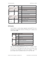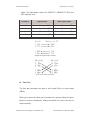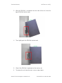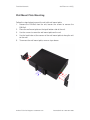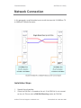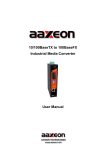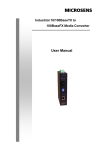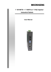
1
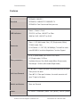
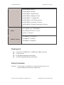
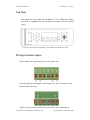
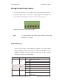
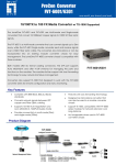
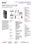
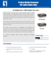
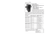
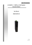
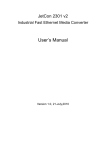
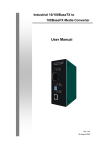
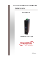
Industrial 10/100BaseTX to 100BaseFX
Media Converter
User Manual
SISTF101x-211-LR(T)
V1.02
August-2010
Transition Networks
SISTF101x-211-LR(T)
FCC Warning
This Equipment has been tested and found to comply with the limits for a
Class A digital device, pursuant to Part 15 of the FCC rules. These limits
are
designed
to
provide
reasonable
protection
against
harmful
interference in a residential installation. This equipment generates, uses,
and can radiate radio frequency energy. It may cause harmful interference
to radio communications if the equipment is not installed and used in
accordance with the instructions. However, there is no guarantee that
interference will not occur in a particular installation. If this equipment
does cause harmful interference to radio or television reception, which can
be determined by turning the equipment off and on, the user is
encouraged to try to correct the interference by one or more of the
following measures:
Reorient or relocate the receiving antenna.
Increase the separation between the equipment and receiver.
Connect the equipment into an outlet on a circuit different from that to
which the receiver is connected.
Consult the dealer or an experienced radio/TV technician for help.
CE Mark Warning
This is a class A product. In a domestic environment this product may
cause radio interference in which case the user may be required to take
adequate measures.
24-Hour Technical Support: 1-800-260-1312
International: 00-1-952-941-7600
Transition Networks
SISTF101x-211-LR(T)
Content
FCC Warning ....................................................... i
CE Mark Warning ................................................ i
Overview ............................................................. 1
Introduction .............................................................. 1
Features ................................................................... 3
Packing List.............................................................. 5
Safety Precaution..................................................... 5
Hardware Description ......................................... 6
Front Panel............................................................... 6
Top View .................................................................. 7
Wiring the Power Inputs ........................................... 7
Wiring the Fault Alarm Contact ................................ 8
LED Indicators.......................................................... 8
DIP-Switch ............................................................... 9
Ports ....................................................................... 10
Cabling ................................................................... 12
Mounting Installation......................................... 13
24-Hour Technical Support: 1-800-260-1312
International: 00-1-952-941-7600
Transition Networks
SISTF101x-211-LR(T)
DIN-Rail Mounting.................................................. 13
Wall Mount Plate Mounting .................................... 15
Network Connection ......................................... 16
Installation Steps.................................................... 16
Troubleshooting ................................................ 18
24-Hour Technical Support: 1-800-260-1312
International: 00-1-952-941-7600
Transition Networks
SISTF101x-211-LR(T)
Overview
Introduction
The Industrial 10/100Base TX to 100BaseFX Media Converter is a
cost-effective solution for converting between 10/100Base-TX and
100Base-FX cabling. It allows you to extend the cabling distance of
your 100Base-FX network up to 2 kilometers for multi-mode fiber or 30
kilometers for single-mode fiber. The Fast Fiber Converter module gives
you the option to choose from the most popular fiber cabling connectors:
SC multi-mode and single-mode connector.
Fast Fiber Converters Module
The Industrial 10/100Base TX to 100BaseFX Media Converter provides
you with one Fiber connector for your fiber optic cable and one Ethernet
RJ-45 port (Auto MDI/MDIX) for your 100Base-TX copper cable
connection. There are four DIP-switches to set the operation mode for
UTP, Fiber ports and link loss forwarding function.
Dual Power Input
To reduce the risk of power failure, the Industrial 10/100Base TX to
100BaseFX Media Converter provides +12 ~ 48 VDC redundant power
inputs. If there is power failure, Industrial 10/100Base TX to 100BaseFX
Media Converter will automatically switch to the secondary power input.
Flexible Mounting
Industrial 10/100Base TX to 100BaseFX Media Converter is extremely
compact and can be mounted on a DIN-rail or a panel, so it is suitable
for any space-constrained environment.
Advanced Protection
The power line of Industrial 10/100Base TX to 100BaseFX Media
Converter supports up to 3,000 VDC EFT protection, which secure
equipment against unregulated voltage and make systems safer and
more reliable. Meanwhile, 6,000 VDC ESD protections for Ethernet ports
24-Hour Technical Support: 1-800-260-1312
International: 00-1-952-941-7600
Transition Networks
SISTF101x-211-LR(T)
make Industrial 10/100Base TX to 100BaseFX Media Converter more
suitable for harsh environments.
Wide Operating Temperature
The operating temperature of the Industrial 10/100Base TX to
100BaseFX Media Converter is between -40 ~ 75oC (wide operating
temperature model) or -10 ~ 60oC (standard model). With such a wide
range, you can use the Industrial 10/100Base TX to 100BaseFX Media
Converter in some of the harshest industrial environments that exist.
Easy Troubleshooting
LED indicators make troubleshooting quick and easy. The 10/100
Base-TX port has 2 LEDs that display the link status, transmission
speed and collision status. Also the three power indicators P1, P2 and
Fault help you diagnose immediately.
24-Hour Technical Support: 1-800-260-1312
International: 00-1-952-941-7600
Transition Networks
SISTF101x-211-LR(T)
Features
IEEE802.3 10BASE-T
Standard
IEEE802.3u 100BASE-TX/100BASE-FX
IEEE802.3x Flow Control and Back pressure
Power 1, Power 2, Fault
LED Indicators
FDX/COL for Fiber, LNK/ACT for Fiber
100M for RJ45, LNK/ACT for RJ45
Fiber x 1: SC (Multi-mode, 2km), SC (Single-mode, 30km),
Connector
ST(Multi-mode, 2km)
RJ-45 Socket x 1: CAT-3/5 (10/100Mbps) Twisted Pair cable
Auto MDI/MDI-X and Auto-Negotiation Function Support
SC & ST (Multi-mode): 50/125um~62.5/125um
Fiber parameters
SC (Single-mode): 9/125um
Available distance: 2km (Multi-mode)/30km (Single-mode)
Wavelength: 1310nm (Multi-mode/Single-mode)
TX
Link Lose Forward
Fiber: If TX port link down, the media converter will force
Fiber port to link down
Fiber
TX: If Fiber port link down, the media converter will
force TX port to link down
Switch architecture
Store and Forward
Power
12~48VDC Redundant power with polarity reverse protect
24-Hour Technical Support: 1-800-260-1312
International: 00-1-952-941-7600
Transition Networks
SISTF101x-211-LR(T)
function and removable terminal block ;
SISTF1011-211-LRT supports 24VAC (18~30V)
Power Consumption
Standard Operating
3.36 Watts (Max.)
-10
~ +60
(32 F~140 F)
-40
~ +75
(-40 F~167 F)
Temperature
Extend Operating
Temperature
(-LRT models only)
Operating Humidity
5% to 95% (non-condensing)
Storage environment
-40
Dimensions
~ +85
(-40 F~185 F)
Metal case. IP-30,
30mm (W) x 95mm (D) x 140mm (H)
MTBF
384816 hrs
Installation
DIN Rail and Wall Mount Design
FCC Class A
EN61000-6-4
EMC
EN61000-6-2
EN61000-4-2 (ESD)
EN61000-4-3 (Radiated RFI)
24-Hour Technical Support: 1-800-260-1312
International: 00-1-952-941-7600
Transition Networks
SISTF101x-211-LR(T)
EN61000-4-4 (Burst)
EN61000-4-5 (Surge)
EN61000-4-6 (Induced RFI)
EN61000-4-8 (Magnetic Field)
EN61000-4-11 (Voltage Dip)
EN61000-4-12 (Oscillatory waves)
EN61000-3-2 (Harmonics Current)
EN61000-3-3 (Voltage Fluctuation & Flickers)
UL 60950, cUL, CE/EN60950-1
UL 508 (SISTF1011-211-LRT)
Safety
Class 1 Division 2
IEC60068-2-32 (Free fall),
Stability Testing
IEC60068-2-27 (Shock),
IEC60068-2-6 (Vibration)
Packing List
1 x Industrial 10/100BaseTX to 100BaseFX Media Converter
1 x User manual
2 x Wall Mounting Bracket and Screws
1 x DIN-rail Mounting Bracket and Screws
Safety Precaution
Attention IF DC voltage is supplied by an external circuit, please use a
protection device on the power supply input.
24-Hour Technical Support: 1-800-260-1312
International: 00-1-952-941-7600
Transition Networks
SISTF101x-211-LR(T)
Hardware Description
The Industrial 10/100Base TX to 100BaseFX Media Converter dimension:
30mm (W) x 95mm (D) x 140mm (H)
Front Panel
The Front Panel of the Industrial 10/100Base TX to 100BaseFX Media
Converter is shown as follows.
Front Panel of the Industrial 10/100TX to 100FX Media Converter
24-Hour Technical Support: 1-800-260-1312
International: 00-1-952-941-7600
Transition Networks
SISTF101x-211-LR(T)
Top View
The top panel of the Industrial 10/100Base TX to 100BaseFX Media
Converter is equipped one terminal block connector of two DC power
inputs.
Top Panel of the Industrial 10/100Base TX to 100BaseFX Media Converter
Wiring the Power Inputs
Please follow the steps below to insert the power wire.
Insert the positive and negative wires into the V+ and V- contacts on the
terminal block connector.
Tighten the wire-clamp screws for preventing the wires from loosing.
24-Hour Technical Support: 1-800-260-1312
International: 00-1-952-941-7600
Transition Networks
SISTF101x-211-LR(T)
Wiring the Fault Alarm Contact
The fault alarm contact is in the middle of the terminal block connector as
the picture shows below. Fault status, including power failure/port link
failure, will be indicated by the contacts forming an open circuit.
Insert the wires into the fault alarm contact.
The wire gauge for the terminal block should be in the range
Note
between 12~ 24 AWG.
LED Indicators
There are a few LEDs, which display the power status and network
status, located on the front panel of the Industrial 10/100Base TX to
100BaseFX Media Converter; each of them has its own specific
meaning as shown in the table below.
LED
P1
P2
Fault
Color
Green
Green
Red
Description
ON
Power input 1 is active
OFF
Power input 1 is inactive
BLK
---
On
Power input 2 is active
Off
Power input 2 is inactive
BLK
---
On
Power input 1 or 2 has failed
Off
24-Hour Technical Support: 1-800-260-1312
Power input 1 and 2 are both functional, or no
power inputs
International: 00-1-952-941-7600
Transition Networks
FDX/COL For
fiber
LNK/ACT For
fiber
100M For
SISTF101x-211-LR(T)
Amber
Green
Amber
RJ-45
LNK/ACT
Green
For RJ-45
BLK
---
On
Full-duplex mode
BLK
Packet collision occurred
Off
Half-duplex mode
On
Connected to network
BLK
Networking is active
Off
Not connected to network
On
Link to 100Mbps network
BLK
---
Off
Link to 10Mbps network
On
Connected to network
BLK
Networking is active
Off
Not connected to network
DIP-Switch
The DIP-Switch is used to configure operation mode for LLF (Link Loss
Forwarding) and operation mode for UTP/Fiber port. The default value
of DIP-switch is OFF.
S/W No
1
2
3
4
Status
Description
ON
Enables Port/Power Alarm
OFF
Disable Port/Power Alarm
ON
Enables LLF
OFF
Disables LLF
ON
100Base-FX Half-mode
OFF
100Base-FX Full-mode
ON
Media mode (100TX to 100FX)
OFF
Switching mode
Link Lose Forwarding (DIP-Switch 2): When LLF enabled, it allows
UTP link failures to be reported to the fiber side and also allows Fiber
link failures to be reported to the UTP side. Therefore, a link fault
pass-through feature is provided in both the UTP and Fiber sides.
24-Hour Technical Support: 1-800-260-1312
International: 00-1-952-941-7600
Transition Networks
SISTF101x-211-LR(T)
Media mode (DIP-Switch 4): When media mode is enabled (ON), it
operates with the minimum latency. The transmission flow does not wait
until entire frame is ready, but instead it forwards the received data
immediately after the data being received. The TP port should be forced
to 100M in this application. When the DIP-Switch is in switching mode
(OFF), the converter function is the same as a Switch Hub.
Note
Please don’t change the DIP-switch setting when UTP or fiber port
is transmitting or receiving data. It may cause some data errors.
Besides, if you change the DIP-switch setting, please power off
the converter and power on again to make the setting effective.
Ports
RJ-45 ports (Auto MDI/MDIX): The RJ-45 ports are auto-sensing for
10Base-T or 100Base-TX devices connections. Auto MDI/MDIX means
that you can connect to another switch or workstation without changing
straight through or crossover cabling. See figures as below for straight
through and crossover cable schematic.
RJ-45 Pin Assignments
Note
Pin Number
Assignment
1
Tx+
2
Tx-
3
Rx+
6
Rx-
“+” and “-” signs represent the polarity of the wires that make up
each wire pair.
All ports on this unit support automatic MDI/MDI-X operation, you can
use straight-through cables (See Figure below) for all network
connections to PCs or servers, or to other switches or hubs. In
straight-through cable, pins 1, 2, 3, and 6, at one end of the cable, are
connected straight through to pins 1, 2, 3 and 6 at the other end of the
24-Hour Technical Support: 1-800-260-1312
International: 00-1-952-941-7600
Transition Networks
SISTF101x-211-LR(T)
cable. The table below shows the 10BASE-T/ 100BASE-TX MDI and
MDI-X port pin outs.
Pin MDI-X
Signal Name
MDI Signal Name
1
Receive Data plus (RD+)
Transmit Data plus (TD+)
2
Receive Data minus (RD-)
Transmit Data minus (TD-)
3
Transmit Data plus (TD+)
Receive Data plus (RD+)
6
Transmit Data minus (TD-)
Receive Data minus (RD-)
Straight Through Cable Schematic
Cross Over Cable Schematic
Fiber Port
The fiber port connector can work in multi mode (2Km) or single mode
(30Km).
When you connect the fiber port to another one, please follow the figure
below to connect accordingly. Wrong connection will cause the port to
work incorrectly.
24-Hour Technical Support: 1-800-260-1312
International: 00-1-952-941-7600
Transition Networks
ATTENTION
SISTF101x-211-LR(T)
This is a Class 1 Laser/LED product. Don’t stare into
the Laser/LED Beam.
Cabling
Twisted-pair segments can be connected with unshielded twisted pair
(UTP) or shielded twisted pair (STP) cable. The cable must comply with
the IEEE 802.3u 100Base TX standard for Category 5. The cable between
the converter and the link partner (converter, switch, hub, workstation,
etc.) must be less than 100 meters (328 ft.) long.
Fiber segments using single-mode connector type must use 9/125µm
single-mode fiber cable. User can connect two devices up to 30
Kilometers distance.
Fiber segment using multi-mode connector type must use 50 or 62.5/125
µm multi-mode fiber cable. User can connect two devices up to 2Km
distance.
24-Hour Technical Support: 1-800-260-1312
International: 00-1-952-941-7600
Transition Networks
SISTF101x-211-LR(T)
Mounting Installation
DIN-Rail Mounting
The DIN-Rail is screwed on the unit at the factory. If the DIN-Rail is not
screwed on the unit, please see the pictures and follow the steps below to
screw the DIN-Rail on the unit.
1.
Use the screws to screw the DIN-Rail on the rear side of the unit.
2.
To remove the DIN-Rail, reverse the step 1.
24-Hour Technical Support: 1-800-260-1312
International: 00-1-952-941-7600
Transition Networks
3.
SISTF101x-211-LR(T)
After the DIN-Rail is screwed on the rear side of the unit, insert the
top of DIN-Rail into the track.
4.
Then, lightly push the DIN-Rail into the track.
5.
Check if the DIN-Rail is tightened on the track or not.
6.
To remove the unit from the track, reverse steps above.
24-Hour Technical Support: 1-800-260-1312
International: 00-1-952-941-7600
Transition Networks
SISTF101x-211-LR(T)
Wall Mount Plate Mounting
Follow the steps below to mount the unit with wall mount plate.
1. Remove the DIN-Rail from the unit; loosen the screws to remove the
DIN-Rail.
2.
Place the wall mount plate on the top & bottom side of the unit.
3.
Use the screws to screw the wall mount plate on the unit.
4.
Use the hook holes at the corners of the wall mount plate to hang the unit
5.
on the wall.
To remove the wall mount plate, reverse steps above.
24-Hour Technical Support: 1-800-260-1312
International: 00-1-952-941-7600
Transition Networks
SISTF101x-211-LR(T)
Network Connection
In this paragraph, we will describe how to install the Industrial 10/100Base TX
to 100BaseFX Media Converter.
Installation Steps
1.
2.
Unpack the unit packing.
Check the DIN-Rail is screwed on the unit. If the DIN-Rail is not screwed
on the unit. Please refer to DIN-Rail Mounting section for DIN-Rail
24-Hour Technical Support: 1-800-260-1312
International: 00-1-952-941-7600
Transition Networks
SISTF101x-211-LR(T)
3.
installation. If you want to wall mount the unit, then please refer to Wall
Mount Plate Mounting section for wall mount plate installation.
To hang the unit on the DIN-Rail track or wall, please refer to the
4.
Mounting Installation section.
Power on the Unit. How to wire the power; please refer to the Wiring the
5.
6.
Power Inputs section. The power LED on the unit will light up. Please
refer to the LED Indicators section for meaning of LED lights.
Prepare the twisted-pair, straight through Category 5 cable for Ethernet
connection.
Insert one side of Category 5 cables into the Ethernet port (RJ-45 port)
and another side of category 5 cables to the network devices’ Ethernet
port (RJ-45 port), ex: switch, PC, or Server. The UTP port (RJ-45) LED on
the unit will light up when the cable connected with the network device.
7.
Please refer to the LED Indicators section for LED light meaning.
Connect one end of the fiber cable to the SC single-mode connector on
this converter and the other end of the fiber cable to the SC single-mode
connector on the other 100 Base-FX device.
Note
8.
Be sure the connected network devices support MDI/MDI-X. If it
does not support, then use the crossover category 5 cable.
When all connections are all set and LED lights all show in normal, the
installation is complete.
24-Hour Technical Support: 1-800-260-1312
International: 00-1-952-941-7600
Transition Networks
SISTF101x-211-LR(T)
Troubleshooting
Verify that you are using the right power cord/adapter (DC 12-48V),
please don’t use a power adapter with DC output higher than the power
input range as above, or it may damage the device.
Select the proper UTP/STP cable to construct your network. Please check
that you are using the right cable. Use unshielded twisted-pair (UTP) or
shield twisted-pair (STP) cable for RJ-45 connections: 100
4 or 5 cables for 10Mbps connections or 100
Category 3,
Category 5 cable for
100Mbps connections. Also be sure that the length of any twisted-pair
connection does not exceed 100 meters (328 feet).
Diagnosing LED Indicators: the unit can be easily monitored through
panel indicators to assist in identifying problems, which describe common
problems you may encounter and where you can find possible solutions.
IF the power indicator does not light on when the power cord is plugged in,
you may have a problem with power cord. Check for loose power
connections, power losses or surges at power outlet. If you still cannot
resolve the problem, contact your local dealer for assistance.
If the LED indicators are normal and the connected cables are correct and
the packets still cannot transmit check your system’s Ethernet devices’
configuration or status.
24-Hour Technical Support: 1-800-260-1312
International: 00-1-952-941-7600