1
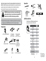
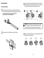
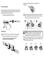
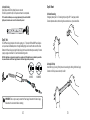
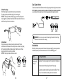
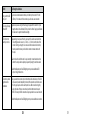
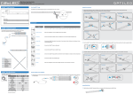
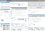
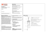
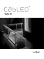
Starter Kit
User’s Manual
CONTENTS
Unpack..................................................................................................... 2
Required Tools.......................................................................................... 3
Strip Specification.................................................................................... 3
Warnings and Cautions............................................................................. 4-5
Plan Your Installation................................................................................ 6
Measure and Mark Surface....................................................................... 6-7
Mark and Cut LED Strip............................................................................ 8-9
Installation............................................................................................... 10-14
Test.......................................................................................................... 14
Mounting.................................................................................................. 15-16
Connect to Power...................................................................................... 17
Troubleshooting........................................................................................ 17-18
1
BEFORE YOU BEGIN, MAKE SURE YOU CAREFULLY READ AND UNDERSTAND THE INSTRUCTIONS IN THIS
MANUAL. This CabLED kit includes an assortment of components to cover a variety of indoor or outdoor
applications. Our goal is to make this installation easy for you. Please follow the instructions in
the order presented in this manual and be sure to observe all warnings and cautions.
IMPORTANT: Each connector consists of two parts, a top and bottom, which are
partially assembled at the factory. Do not push the connectors together BEFORE
installation. Do not cut the LED strip before planning your installation.
Required Tools:
Pliers
Scissors
Tape Measure
Level
Pencil
1
Safety Glasses
2
CabLED Strip Specification
Make certain the following components are included in the package. If any of the parts are missing
or damaged please contact OptiLED Customer Service. Parts are not shown in actual size.
Package Contains:
1 x 6’ LED Indoor/Outdoor Lighting Strip
2 x 24” Jumper Cables
Connects 2 CabLEDTM strips with a 61cm/24inch flexible cable
1 x Power Supply Connector
Used in all installations.
Connects CabLEDTM strips to power supply
1 x Dimmable on/off Switch
6 x 4” Channeling Strips
2 x End Caps
Protects
1 x 18W Indoor/Outdoor Power Supply Used in all installations.
TM
end of CabLED strip that is not
connected to a connector.
1 x Cutting Jig
2
1 x 6’ of 3M™ 2-Way Adhesive Tape
The CabLED strip uses CREE High Brightness LED lights set
every inch and can be cut every 7 inches (18cm).
Input Voltage
Input Current
Power
Weight
*Lifetime
Beam Angle
Lumen/Meter
CRI
No. of LED/Segment
LED Pitch
IP Rating
Operating Temperature
Storage Temperature
Min. Bending Radius
Max. Connection Length
with an 18W Power Supply
Max. Connection Length
with a 30W Power Supply
Max. Connection Length
with a 60W Power Supply
3
Warm White
(3500K)
24V
154mA
3.7W/m
3.5oz/m
35,000h
120˚
170lm
80
6pcs
30mm
IP65
-20˚~50˚
-25˚~60˚
3.9in
15ft
25ft
50ft
*With 70% lumen maintenance
30 & 60 watt power supplies can
be purchased at homedepot.com
or through CabLEDLighting.com
IMPORTANT WARNINGS AND CAUTIONS!
WARNING: A WARNING alerts you to the possibility of serious injury or death if you do
not follow the instructions.
CAUTION: Create layout plan before installation. Locate power supply, determine suitable mounting methods
and connectors, measure and calculate the length of CabLED LED required. LED strip can only be
cut at every 7 inches (18cm) and must be cut exactly on the indicated mark.
CAUTION: A CAUTION alerts you to the possibility of damage to or destruction of the equipment
if you do not follow the corresponding instructions.
Use only CabLED connectors, channeling, inline dimmer and power supply.
WARNING: Do not open, dismantle or attempt to repair the LED strip, bottom half of the connectors, inline
dimmer or power supply. There are no user serviceable parts. Products should be installed in
accordance with the owner’s manual, current electrical codes and/or the current National Electric
Code (NEC). Improper installation may present a possible shock or fire hazard. Always make sure
the LED strip is disconnected from the power source before cutting, connecting, mounting or
modifying in any way.
Do not use acid or alkaline liquid to clean.
The LED strip is water resistant, not water proof. Do not submerge. Mount power supply at
least one foot above the ground. Do not submerge in water.
Material may become brittle when cold. Do not install where it may be stepped on or
subject to physical damage.
Safety measures must be observed at all times during the installation of this product.
Use proper safety gear and tools during the installation process to prevent physical injury.
Do not install near flammable liquids.
Suitable for indoor and outdoor use
Risk of electric shock. Do not use with extension cord near water or where water may
accumulate. For use only on GFCI proctected circuits.
Do not look directly at the LED lights in the CabLED strip when lit.
Do not mount or support flexible light in a manner that can damage the outer jacket
or cord insulation.
Risk of fire and electric shock. Uncoil flexible light prior to plugging in.
4
5
Step 1: Plan Your Installation
IMPORTANT: The connectors consist of two parts, a top and bottom, which are partially
assembled at the factory. Do not push the connectors together or cut the
LED strip BEFORE you have planned your installation.
2.1 For Use in a Straight Area
Measure and mark the surface where the LED strip will be installed.
Use the Power Supply, Power Supply Connector, 24” Jumper Cable and End Cap for installation.
We have included an assortment of components to cover a variety of indoor or outdoor applications.
Plan your installation carefully to decide exactly which components your installation requires.
IMPORTANT: Place Power Supply
near outlet and off the ground.
All installations require the Power Supply Connector, which connects the LED strip to the Power Supply
and the End Cap which is used to protect the other end of the LED strip.
Step 2: Measure and Mark Surface
There are a few things to consider when measuring for your installation.
• Determine where your Power Supply will be mounted and plan your installation so the
Power Supply Connector will be near the wall outlet.
• The connectors add about 1/2 inch (1.27cm) of length to the end of the LED strip and
the LED strip may ONLY be cut along the cut line marked at every 7 inches (17.78cm) on
the top of the strip.
2.2 For Use in a Corner Area
Measure and mark the surface where the LED strip will be installed.
Use the Power Supply, Power Supply Connector, 24” Jumper Cable and End Cap for installation.
• It may be useful to lay out the strip and connectors to visualize how the components
fit together in your space before you begin. DO NOT PUSH CONNECTORS TOGETHER.
IMPORTANT: Place Power Supply
near outlet and off the ground.
• Measure and mark the surface where the LED strip will be installed.
IMPORTANT: The LED strip may ONLY be cut every 7 inches (17.78cm), indicated by a cut
line on the LED side of the strip. When you are measuring for your installation, if the total
length is not a multiple of 7, then adjust the plan of your layout to be cut on the nearest mark.
6
7
Step 3: Mark and Cut LED Strip
3.1 Mark LED Strip
Hold the LED strip up to the surface you just marked, locate nearest cut line and mark.
3.2 Cut LED Strip
Use a pair of sharp scissors to cut the LED strip EXACTLY on the cut lines you have marked.
TIP: You can use the jig included in kit to ensure a straight and even cut.
TIP: You can use the jig included in kit to ensure a straight and even cut.
1
2
1
2
Rotate the strip along the surface you marked, locate nearest cut line and mark.
Rotate and mark again for three-sided area. Adjust your layout if necessary.
3
4
8
9
Step 4: Install Connectors
4.1C Using pliers, apply even pressure to the bottom and top halves of the connector to push connector
together, securing LED strip inside. After compressing the center of the connector, check to make
sure the left and right side of the connector have clicked into place and are secure.
4.1 Install Power Supply Connector
4.1A Find the end of the LED strip that will be installed nearest to the power. With LED side facing up,
slide the strip into the opening in bottom half of the Power Supply Connector until it reaches the end.
TIP: To make this installation process easier, apply petroleum jelly to the end of the CabLED
1
2
3
(lightly coated) to make it easier to insert. This will not hurt the product.
4.1B Make sure notches on the side of the CabLED are fully inserted inside the connector.
IMPORTANT: When using pliers that do not cover the surface of the connector, apply pressure
to one side of the connector to push the connector together. Without moving the strip or the
connector, carefully rotate the pliers to apply pressure to the other side of the connector.
4.1D Make sure both sides of the bottom half of the connector snap into the top half. Gently pull the LED strip to make sure you have installed it properly.
CORRECT
10
INCORRECT
INCORRECT
11
INCORRECT
4.3B Turn the cable over and make sure the LED strip is pushed completely to the back
of the cable.
4.2 Install Inline Dimmer (Optional)
If included in your installation, the Inline on/off Dimmer Switch will fit between the Power Supply Connector
and the Power Supply. Unplug the Power Supply from the AC outlet before connecting. Match the icons on
the Power Supply Connector with the icons on the Inline Dimmer.
NOTE: The Inline Dimmer is optional and not required for a complete install.
4.3C Using pliers, apply even pressure to the bottom and top halves of the connector to push connector
together, securing LED strip inside. After compressing the center of the connector, check to make
sure the left and right side of the connector have clicked into place and are secure.
1
4.3 Install Jumper Cable
4.3A With the LED side of each strip facing up, insert one strip into one side of the Jumper Cable
and push to the end. Insert the other strip into the other side and push it to the end.
TIP: To make this installation process easier, apply petroleum jelly to the end of the CabLED
(lightly coated) to make it easier to insert. This will not hurt the product.
2
IMPORTANT: When using pliers that do not cover the surface of the connector, apply pressure
to one side of the connector to push the connector together. Without moving the strip or the
connector, carefully rotate the pliers to apply pressure to the other side of the connector.
4.3D Make sure both sides of the bottom half of the connector snap into the top half. Gently pull the LED strip to make sure you have installed it properly.
CORRECT
12
3
INCORRECT
INCORRECT
13
INCORRECT
Step 6: Mount
4.4 Install End Cap
Slide End Cap onto LED strip that will have no connector.
The End Cap protects the strip. End Cap does not have to be compressed.
6.1 Mount Channeling
Strategically mount your 6 x 4” channeling strips using the 3M™ 2-way tape provided.
To obtain optimum adhesion, the bonding surfaces must be clean, dry and well unified.
TIP: To make this installation process easier, apply petroleum jelly to the end of the CabLED
(lightly coated) to make it easier to insert. This will not hurt the product.
Step 5: Test
The 18W Power Supply included in this kit will support up to 15’ of product. 30W and 60W Power Supplies
can be purchased at HomeDepot.com or through CabLEDLighting.com. Connect the other end of the Inline
Dimmer to the Power Supply and plug the Power Supply into the wall outlet to test your assembly. If it works
properly, unplug and continue. If not, see the Troubleshooting section.
NOTE: The Inline Dimmer is optional and not required for a complete install. If the Inline Dimmer is not included in your installation, connect the other end of the Power Supply Connector to the Power Supply and test your assembly.
6.2 Install LED Strip
Install LED strip by pressing it firmly into each channeling strip. Working from Power Supply
Connector to End Cap, make certain strip lies flat.
CORRECT
INCORRECT
IMPORTANT: There is only one way to connect the Power Supply Connector to the Power Supply.
Make certain the icons match before connecting.
14
15
Step 7: Connect to Power
6.3 Mount Power Supply
Position Power Supply near power outlet and secure to your desired surface.
For outdoor applications, position Power Supply 1 foot above the ground.
IMPORTANT: Do not plug into outlet until Power Supply is secured. Power Supply should
only be plugged into a weatherproof covered Class A GFCI receptacle. Do not install or use
within 10 feet of a pool. Do not use in a bathroom.
Connect the other end of the Inline Dimmer to the Power Supply and plug the Power Supply into the wall outlet.
NOTE: The Inline Dimmer is optional and not required for a complete install. If the Inline Dimmer is not included in your installation,
connect the other end of the Power Supply Connector to the Power Supply and plug the Power Supply into the wall outlet.
CORRECT
6.4 Mount Dimmer
Position dimmer near power outlet and secure to your desired surface. The Inline
on/off Dimmer Switch fits between the Power Supply Connector and Power Supply. Unplug
the Power Supply from the AC outlet before connecting. Match the icons on the Power
Supply Connector with the icons on the Inline Dimmer.
IMPORTANT: Do not plug into outlet until dimmer is secured.
IMPORTANT: There is only one way to connect the Power Supply Connector to the Power Supply.
Make certain the icons match before connecting.
TROUBLESHOOTING
Most of the problems you may encounter will be caused by improper assembly. If you have any questions or
need additional parts, please contact our customer service or visit us at CabLEDLighting.com.
ISSUE
None of the LED
strip is lit
CORRECT
INCORRECT
INCORRECT
Go Through the Solutions:
Make sure Power Supply is plugged in and the AC power outlet is getting power.
Check connection from Power Supply Connector to Power Supply.
Check the connection on the Power Supply Connector to the LED strip. Pull the
strip. If it comes out of the connector, you will need a new connector.
16
17
ISSUE
Go Through the Solutions:
Only part of the LED
strip is lit
Check all connectors attached to the part of the strip that is not lit. Pull the
LED strip. If it comes out of the connector, you will need a new connector.
LED strip is flashing
ON and OFF
Make sure you are using the Power Supply shipped with the Starter Kit. If you
bought another kit or additional LED strip, check the Power Supply specifications
to make sure it supports the additional length.
LED strip not cut
exactly on cut line
Depending on how you cut the strip, you may still be able to save that section.
The cutting tolerance is about +/-3 mm (+/- 1/8 inch) on either side of the
cut line. Cutting in a straight line is crucial and the two wires inside the strip
must be pushed to the very end inside the connector to make contact with
the pins.
Go to the cut line before the cut line you incorrectly cut and make the section
shorter. You may be able to adjust your layout by moving the sections around.
Visit HomeDepot.com or CabLEDLighting.com to purchase additional LED
strips or Straight Connectors.
Connectors pushed
together before
installation
If you pushed the connector top into the bottom before installation or if the LED
strip was not pushed completely to the end of the connector and did not secure
the strip, you may be able to save the part. Use a flat screw driver to gently
widen the sides of the top connector and push the bottom connector apart.
NOTE: This may not fix the connector and you may need to use a new connector.
Visit HomeDepot.com or CabLEDLighting.com to purchase additional connectors.
18
19
OPTILED Technology LLC
Raritan Center Business Park
30 Campus Drive, Bldg CP-2
Edison, NJ 08837 (1-855-533-6268)
[email protected]
CabLEDLighting.com