1
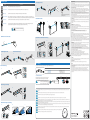
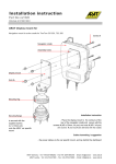
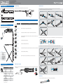
8000 Series Quick Start Guide
Flexible Linear Lighting System
The versatile indoor and outdoor water resistant lighting solution.
CabLED™ Strip Dimension
30mm
30mm
15mm
Cut CabLED™ Strip
Install Connectors
Cut CabLED™ strip to desired length along the cut mark indicated every 18cm / 7inches.
A
With the LED side facing up, slide one CabLED™ strip into the opening in bottom half of one side of the connector until it reaches the end.
Repeat with the other CabLED™ strips in the other sides of the connector if required.
12mm
180mm
PS-Link Connector
I-Connector
Jumper Cable
L-Connector
T-Connector
U-Connector
5.5mm
Front view
Side view
Connectors
CabLED™ Component Layout
Model
Description
4 Way Power Splitter
Connects four CabLED™ strips to one power supply. Install between power supply and four PS-Link connectors.
PS-Link Connector
Used in ALL installations. Connects CabLED™ strip to power supply.
I-Connector
Connects two lengths of CabLED™ strips in a straight line. Use to extend a length of CabLED™ strip.
Jumper Cable
Connects two CabLED™ strips with a 10cm/ 4inches, 15.2cm/ 6inches, 30.5cm/ 12inches, 61cm/ 24inches, 101.6cm
/ 40 inches flexible cable.
This diagram illustrates possible layouts for the CabLED™ 8000 Series.
Refer to the Component Overview for additional information.
S
OR
E
E
E
E
P
P
P
P
L
P
Power
Supply
AC Outlet
L-Connector
E
U
T-Connector
I
J
L
P
S
T
U
X
look for ridges
on
each
side
of strip
End Cap
I-Connector
Jumper Cable
L-Connector
PS-Link Connector
4 Way Power Splitter
T-Connector
U-Connector
X-Connector
slide until
!
all ridges are covered
Connects three CabLED™ strips in a flexible T shape.
C
I
Push the CabLED™ strip completely into the connector. The ridges on each side of the CabLED™ strip will be covered when the strip is properly installed.
T
U-Connector
E
B
Connects two CabLED™ strips at a right angle.
E
Connectors
X-Connector
Using pliers, apply even pressure to the bottom and top halves of the connector to push connector together, securing CabLED™ strip inside.
Connects two CabLED™ strips parallel to each other for twice the brightness or a balance of colour temperature.
PS-Link Connector
I-Connector
Jumper Cable
L-Connector
T-Connector
U-Connector
E
X
X-Connector
Connects four CabLED™ strips at flexible angles.
End Cap
Used in ALL installations. Protects end of CabLED™ strip that is not connected to a connector.
J
E
J
CabLED™ Strip Specification
The CabLED™ strip uses CREE High Brightness LED lights set every inch and can
be cut every 18cm / 7inches.
Warm White
Cool White
(3500K)
(6500K)
Input Voltage
24V
Input Current
154mA
Power
3.7W/m
100g/m
Weight
35,000h
*Lifetime
120o
Beam Angle
170lm
220lm
Lumen/ Meter
80
72
CRI
No. of LED/Segment
6pcs
LED Pitch
30mm
IP Rating
IP65
Operating Temp.
-20o ~ 50o
StorageTemperature
-25o ~ 60o
10cm
Min. Bending Radius
25m
Max. Connection Length
*With 70% lumen maintenance
Install 4 Way Power Splitter
A
X-Connector
Match the icons on each PS-Link Connector with the icons on the 4 Way Power Splitter. Repeat the same connection method with the power supply and
the 4 Way Splitter.
!
Install End Cap
A
Slide End Cap onto CabLED™ strip that will have no connector. The End Cap protects the CabLED™strip.
Mounting Options
Install Edge Bracket
Model
Description
A
Bridge Bracket
Holds CabLED™ strip securely in place using two screws.
Channel Bracket
It installs easily with one screw and is barely visible after CabLED™ strip is snapped into place.
Channeling
CabLED™ strip snaps securely into channeling that runs the length of the installation.
Angle Channeling
Angle Channeling fits into the corner of two surfaces and directs the light at a 30 degree angle. You may install it so
the light points up or down. CabLED™ strip snaps securely into Angle Channeling that runs the length of the installation.
Edge Bracket
Use for flush mount installations such as along a baseboard. Suitable for use in high traffic areas.
Garden Stake
Use for outdoor ground installations. Holds the CabLED™ above ground so it will not be submerged in water and
adjusts to direct the angle of light from 0 to 135 degrees. May be used with Channeling.
B
C
Adjust placement if necessary when
tightening screws.
Install Garden Stake
A
!
ELECTRICAL RATING
To avoid any malfunctions of the system, and to protect against electrical shock, fire or physical injury, please
observe the following:
This system has been designed to work with 100-240 volt AC current. Connection to a line voltage other than that
may create a safety and fire hazard and may damage the system. If you are unsure of the type of power supply to
your home, consult your local power company or a qualified service technician.
B
POWER SOURCE
Do not modify the plug provided with the product – If it will not fit the outlet, have a proper outlet installed by a
qualified electrician.
Damaged or deformed power cords are hazardous and should be replaced immediately by a qualified service
technician.
C
OPERATION
Do not operate with the flexible light tightly coiled.
Do not puncture, cut, shorten, or splice the flexible lighting.
Unplug the unit and the AC power adapter from the electrical outlet during electrical storms or when unused for
long periods of time to prevent damage.
For outdoor use units, make sure that all connections and the end cap in the last segment are tightly secured to
preclude the entry of water.
Do not exceed the recommended length of CabLED™ strip listed for each power supply.
Do not look directly into the LED lights when lit. They are powerful and could damage your vision.
M2.9 (#4) screw is recommended
m
41c
31- "-16"
12
Mark Placement for Brackets
Install Garden Stake With Channeling
A
31-41cm
12"-16"
D
C
B
Install Channel Bracket
A
A
snap
into
lip
B
snap
into
lip
snap
in
place
LOCATION
Place power supply well above the ground or in an area they will NOT be submerged in water or other liquids.
Power Supply
The CabLED™ strip and components
are rated IP65, weather proof only. Do not submerge the flexible lighting in
liquids, or use the product in the vicinity of standing water or other liquids.
Keep all components away from extreme heat sources such as heating vents, radiators, electric heaters and fire
pits.
Do not cover this product as the covering may cause the flexible light to overheat and melt or ignite.
Do not submerge the flexible light in liquids, or use the product in the vicinity of standing water or other liquids.
Do not route the cord or flexible lighting through walls, doors, windows or any like part of the building structure.
Place CabLED™ strip so it will not shine directly into people's eyes.
INSTALLATION
Safety measures must be observed at all times during the installation of this product. Use proper safety gear and
tools during the installation process to prevent physical injury.
Products should be installed in accordance with the user manual, current electrical codes and/or the current
National Electric Code (NEC). Improper installation may cause a possible shock or fire hazard.
To avoid electrical shock and/or damage to the system, do not handle the components with wet hands.
Always make sure the CabLED strip is disconnected from the power source before cutting, connecting, mounting
or modifying in any way. Do NOT dismantle the CabLED strip itself.
Do not coil the strip into a tight circle with a diameter less than 20cm/8 inches or bend it in half as it may damage
the LEDs embedded in the CabLED™ strip.
Do not subject the flexible CabLED™ strip to continuous flexing.
Do not use if there is any damage to the light or cord insulation. Inspect periodically.
CabLED™ connectors have sharp pins inside. Follow instructions when handling.
Use only CabLED™ connectors, mountings and power supply. Carefully follow the instructions to install and
mount.
Secure this flexible strip using only the hangers or clips provided. Do not secure this product or its cord with
staples, nails, or like means that may damage the insulation.
slide
into
top
Install Bridge Bracket
GROUNDING INSTRUCTIONS
This product must be grounded. If it should malfunction or breakdown, grounding provides a path of least
resistance for electric current to reduce the risk of electric shock. This product is equipped with a cord having an
equipment-grounding conductor and a grounding plug. The plug must be plugged into an appropriate outlet
that is properly installed and grounded in accordance with all local codes and ordinances.
WARNING – Improper connection of the equipment-grounding conductor is able to result in a risk of electric
shock. Check with a qualified electrician or serviceman if you are in doubt as to whether the product is properly
grounded. Do not modify the plug provided with the product - If it will not fit the outlet, have a proper outlet
installed by a qualified electrician.
Ground Fault Circuit Interrupter (GFCI) protection should be provided on the circuits or outlet to be used for the
outdoor use flexible lighting product. Receptacles are available with built-in GFCI protection for this measure of
safety. If you are unsure of the type of outlet, consult a qualified service technician to install a GFCI receptacle.
m
41c
31- "-16"
12
CLEANING
Clean only with a dry or slightly damp cloth. Do not use any acid or alkaline liquids, cleansing agents or solvents.
Unplug the system from the wall outlet before cleaning.
NON-USE PERIODS
When left unused for long periods of time, the system should be unplugged from the AC outlet.
Power Supply
Install Channeling
A
Select the correct power supply, determine the length of CabLED™ strip needed.
B
Recommended Power Supply
18 Watt 24VDC
30 Watt 24VDC
60 Watt 24VDC
100 Watt 24VDC
snap
into
lip
snap
into
lip
Recommended Length of CabLED™ Strip
Up to 4.5M / 14.7 Ft
4.5 - 7.5M / 14.7 - 24.6 Ft
7.5 - 15M / 24.6 - 49.2 Ft
15 - 25M / 49.2 - 82 Ft
SERVICE
Always remove the AC power adapter from the electrical outlet before adjusting or inspecting the system. Inspect
your system periodically.
Do not open, dismantle or attempt to repair the CabLED™ strip or the bottom half of the connectors. There are no
user-serviceable parts.
Do not open the cabinets of accessories or power supply. There are no user-serviceable parts. Opening the
cabinets may present a shock hazard, and any modification to the product will void your warranty.
Do not attempt to service the components yourself. If water or any metal objects such as paper clips, wire or
staples accidentally fall inside, then disconnect from the power source immediately and consult an authorized
service center.
Connect to Power
Matching the icons, connect the PS-Link Connector to the
power supply. Plug the power supply into the AC outlet.
!
Install Angle Channeling
A
B
slide
into
!
!
!
!
!
!
!
!
!
!
bottom
snap
into
lip
Install Double Angle Channeling
A
B
C
Double sided tape
slide
into
bottom
snap
into
lip
IMPORTANT: Connect the power supply to the
PS-Link Connector BEFORE plugging
the power supply into the AC outlet.
IMPORTANT: The CabLED™ 8000 system is designed to work ONLY with the power supplies, connectors, mounting options, and accessories listed. Do NOT substitute other products as they may damage
your system.
IMPORTANT: Do not plug into outlet until power supply is secured. Place power supply near outlet and off the ground so there is no chance of it being submerged in water.
IMPORTANT: Risk of fire and electric shock. Uncoil flexible CabLED™ light strip prior to plugging into receptacle.
IMPORTANT: The connectors consist of two parts, a top and bottom, which are partially assembled at the factory. DO NOT push the connectors together before you are ready to install.
IMPORTANT: The CabLED™ strip may ONLY be cut every 18cm/7.09 inches, indicated by a cut line on the LED side of the strip. When you are measuring for your installation, if the total length in inches is not a
multiple of 7, then adjust the plan of your layout to use the nearest cut line marked on the strip.
IMPORTANT: When using pliers that do not cover the entire surface of the connector, hold the connector and strip steady so the CabLED strip remains in position. Carefully rotate the pliers and apply pressure
to each side of the connector, pushing the top and bottom together.
IMPORTANT: There is only one way to connect the 4 Way Power Splitter to the power supply and PS-Link Connectors. Make certain the icons match before connecting. Connect the 4 Way Power Splitter to the
PS-Link Connectors and to the power supply BEFORE plugging the power supply into the AC outlet.
IMPORTANT: There is only one way to connect the PS-Link Connector to the power supply. Make certain the icons match before connecting. Connect the power supply to the PS-Link Connector BEFORE
plugging the power supply into the AC outlet.
IMPORTANT: Use Garden Stakes where CabLED™ strip will be installed on the ground outside. Install so CabLED or connectors will NOT be submerged in water.
IMPORTANT: Do not coil the strip into a tight circle with a diameter less than 20cm/8 inches.
IP65
20cm
N25615
Double sided tape
Email: [email protected]
Website: www.optiled.com
MKT-452/04/11