1
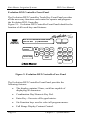
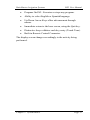
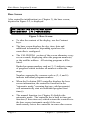
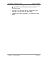
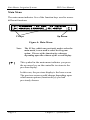
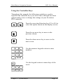
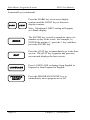
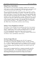
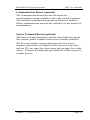
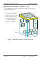
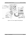
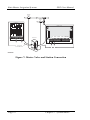
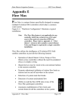
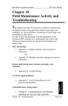
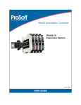
Rain Master Irrigation Systems
DX2 User Manual
Chapter 2
System Basics
The Evolution DX2 Controller contains a comprehensive
feature set to support virtually any conceivable irrigation
system/configuration. In addition to the more traditional
irrigation features, the controller supports multiple sensor inputs,
central communications control, extensive fault diagnostics and
specialized electronics to insure that product reliability is not
compromised. Through use of selected “setup” options, the
controller can be adapted to a specific irrigation application.
Chapter 2:
Chapter 2: System Basics
System Basics
Although the controller provides numerous features and options,
the user interface remains extremely simple. Consequently the
operation of the controller remains “user friendly.”
Page 9
Rain Master Irrigation Systems
DX2 User Manual
Evolution DX2 Controller Front Panel
The Evolution DX2 Controller Touch Key Front Panel provides
all the necessary functions and control to operate and program
the Evolution DX2 Controller.
Figure 2-1: Evolution DX2 Controller Front Panel identifies the
location of all touch keys and features.
REMOTE
CONTROL
SAT 09:15:11AM VALID PGM: NONE
05/01/93 WK1 [F1]=MAIN MENU
CONTRAST
PROGRAM
ON/OFF
Ï
Ð
LANGUAGE
F1
F4
F2
F5
F3
SAT
7
8
9
F6
WED
4
THU
5
FRI
6
QUIT
SUN MON TUE
1
2
3
0
ENTER
Figure 2: Evolution DX2 Controller Face Panel
The Evolution DX2 Controller Front Panel provides the
following features:
•
The display contains 2 lines, each line capable of
displaying 40 characters.
•
Combination Day/Numeric Key Pad.
•
Enter Key - Executes all keypad entries.
•
Six Function keys used to select all program menus.
•
Full Range Display Contrast Control.
Page 10
Chapter 2: System Basics
Rain Master Irrigation Systems
DX2 User Manual
•
Program On/Off - Executes or stops any program.
•
Ability to select English or Spanish language.
•
Up/Down Arrow Keys allow advancement through
menus.
•
Immediate return to the base screen, using the Quit key.
•
Distinctive beep validates each key entry (Touch Tone).
•
Built-in Remote Control Connector.
The display screen changes accordingly to the activity being
performed.
Chapter 2: System Basics
Page 11
Rain Master Irrigation Systems
DX2 User Manual
Base Screen
After controller initialization (see Chapter 3), the base screen,
depicted in Figure 2-2, is displayed.
SAT 09:15:11AM VALID PGM: NONE
06/18/96 WK1 |F1|=MAIN MENU
Figure 3: Base Screen
•
To alter the contrast of the display, use the Contrast
keys.
•
The base screen displays the day, time, date and
additional information, depending upon how the
controller is configured.
•
The VALID PGM: section of the screen alternates every
seven seconds, displaying either the program number(s)
or the satellite address. All existing programs will be
listed.
Dashed program numbers such as (2 -5) indicate a range
of programs which includes all numbers within the
range.
Numbers separated by commas such as (2, 4, and 6)
indicate individual program numbers.
•
When the Evolution DX2 controller displays the base
screen information, the controller functions in the
"automatic mode," meaning that any valid program(s)
will automatically start at established program start
time(s).
•
The manual function (see Chapter 8) disables the
automatic mode. The controller has a built in time-out
function (2 hour time-out) which returns the controller to
the base screen (automatic mode) if the user
inadvertently leaves the controller in some other screen.
Page 12
Chapter 2: System Basics
Rain Master Irrigation Systems
DX2 User Manual
•
User prompts for valid keystroke entry are designated by
| | (vertical bars) with the key name appearing
between the bars.
•
The entry |F1|=MAIN MENU prompts the user to
press the F1 key to access the Main Menu.
•
From the base screen, pressing F1 will display the main
menu.
Chapter 2: System Basics
Page 13
Rain Master Irrigation Systems
DX2 User Manual
Main Menu
The main menu indicates five of the function keys used to access
different functions.
|F1|=PROGRAM |F2|=ISC |F3|=STATUS
|F4|=MANUAL & RAIN OFF |F5|=SETUP
|µ|
F Keys
Up Arrow
Figure 4: Main Menu
Note:
|µ|
The F1 key, which was previously used to select the
main menu, is now used to select the Program
option. The use of the function keys changes
depending upon the contents of the screen display.
This symbol in the main menu indicates you press
the up arrow key on the controller to return to the
previous display.
In this case, the previous display is the base screen.
The previous screen would change depending upon
which menu options (function keys) you had
previously chosen.
Page 14
Chapter 2: System Basics
Rain Master Irrigation Systems
DX2 User Manual
Using the Controller Keys
Throughout this manual, the following symbols are used to
represent the controller keys you use to move through the menu
options and to view or change the settings of your Evolution
DX2 controller.
F1
F2
Press the associated function key (F1 to F6) to
select the option shown on the display screen.
©
Press the up arrow key to move to the
previous screen.
ª
Press the down arrow key to move to the
next screen.
1
0
8
9
5
6
2
3
Use the numeric keypad section to enter
numbers.
ENTER
Use the keypad section to enter days of the
week.
SAT
WED THU
FRI
SUN MON TUE
Chapter 2: System Basics
Page 15
Rain Master Irrigation Systems
DX2 User Manual
Function Keys (continued):
DARK
LIGHT
Press the DARK key to increase display
contrast and the LIGHT key to decrease
display contrast.
Note: Maximum LIGHT setting will appear
as a blank display.
ENTER
QUIT
The ENTER key is used to complete entry of a
number or day of the week. For example, to
ENTER the number 1, press the 1 key and then
press the ENTER key.
Press the QUIT key to immediately go to the base
screen. The QUIT key bypasses any previous
screens and displays the base screen.
LANGUAGE
Press LANGUAGE to change from English to
Espanol or from Espanol to English.
PROGRAM
ON/OFF
Press the PROGRAM ON/OFF key to
immediately turn a program on or off.
Page 16
Chapter 2: System Basics
Rain Master Irrigation Systems
DX2 User Manual
"Beep" Responses
To provide user feedback for keyboard entry, two different beeps
or tones are omitted. A single beep indicates a valid or correct
entry. Rapid successive beeps indicate an invalid entry. For
example, from the base screen, select|F1|and a single beep is
heard. This indicates|F1|is a valid selection. However, from
the base screen select the down arrow and multiple beeps are
heard.
System Configuration
The DX2 Evolution Controller is housed in an all weather
enclosure containing the following assemblies:
•
Keyboard Main Panel Assembly
•
Main Power Switch Box Assembly
•
Master Valve/Pump/Power Board Assembly
•
Station Output Board Assembly
(Quantity varies depending on station configuration)
•
Communication Board Assembly (Optional)
•
Sensor Terminal Board Assembly (Optional)
Keyboard Main Panel
The Keyboard Main Panel assembly consists of a main
microprocessor control board and an optional sensor control
board, which would attached to the main board. Four cables
from this assembly provide the connections to the additional
internal assemblies which include the Master Valve/Pump/Power
board, the Communications board (optional), the Sensor
Terminal (optional), and the Station Output board(s).
Chapter 2: System Basics
Page 17
Rain Master Irrigation Systems
DX2 User Manual
Main Power Switch Box
The Main Power Switch Box assembly contains the controller
main power switch, a dual ground fault interrupter receptacle and
a step-down transformer delivering 12 VAC and 24 VAC.
The ground fault interrupter (GFI) provides an exclusive safety
feature against electrical power hazards. The GFI can sense and
detect any degree of power line shorts and will immediately shut
down the power preventing electrical damage or injury. The GFI
includes a Test switch and a Reset switch. When the Test switch
is pressed, all power will shut down indicating proper operation
of the internal control circuitry. Pressing the Reset switch will
restore power operation. The diagram of Figure 2-5: identifies
the Main Power Switch Box and associated wiring.
Master Valve/Pump/Power Board
The Master Valve/Pump/Power board provides the four outputs
for Master Valve 1, Master Valve 2, Normally Open Valve and
Pump. Additionally, the assembly distributes the 12 VAC and
24 VAC through their respective fuses to the associated
controller assemblies. Figure 2-6: illustrates typical connections
for Master Valve and Station connections.
Station Output Board
The Station Output board delivers the 24 VAC required
operating valve solenoids, lighting systems, security systems,
etc. A Station Output board may be configured with six stations
or 12 stations. The controller enclosure will accept a maximum
of four output boards providing control for a total of up to 48
stations.
Each board is equipped with two common terminals used for
circuit ground return. All common terminals of a multiple
station configuration are essentially identical and may be
interchanged among the boards for wiring convenience.
Page 18
Chapter 2: System Basics
Rain Master Irrigation Systems
DX2 User Manual
Communication Board (optional)
The Communication Board provides the means for
communication among controllers and/or the Central Computer.
The available communication options are Hardwire, Radio or
Phone, communication provides the capability for any number of
configurations.
Sensor Terminal Board (optional)
The Sensor Terminal board provides the direct link between the
flow sensors, and/or weather station devices and the controller.
The flow and weather sensing option provides four sets of
terminal connections; two inputs for flow sensors (or one flow
and one ET), one input for a rain sensor and one input for a wind
sensor. All inputs are dedicated and calibrated to their respective
weather devices.
Chapter 2: System Basics
Page 19
Rain Master Irrigation Systems
DX2 User Manual
DX2 Pedestal Controller Assembly Layout
The assembly layout location within the controller enclosure is
depicted in Figure 2-4.
1 - Keyboard Main Panel
2 - Main Power Switch Box
3 - MV/Pump/Power Bd.
4 - Station Output Bd.
5 - Communications Bd.
6 - Sensor Terminal Bd.
Rear
Front
Figure 5: Pedestal Controller Assembly Layout
Page 20
Chapter 2: System Basics
Rain Master Irrigation Systems
DX2 User Manual
Figure 6: AC Power Supply Wiring Diagram
Chapter 2: System Basics
Page 21
Rain Master Irrigation Systems
DX2 User Manual
MASTER
VALVE
ZONE 2
VALVE
PCDX2-MV
PCDX2-OT12
BLUE
12VAC
ORANGE
24VAC
1 2 3 4 5 6 7 8 9 10 11 12
STATION 2
MV1 MV2 N.O. PUMP COM
COM
TO MASTER VALVE
TO ZONE 2 VALVE
DWG DXMV10A
Figure 7: Master Valve and Station Connection
Page 22
Chapter 2: System Basics