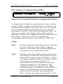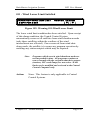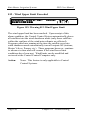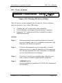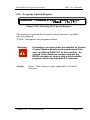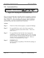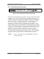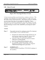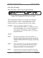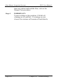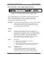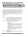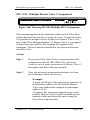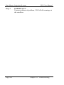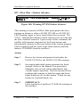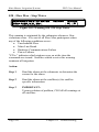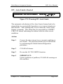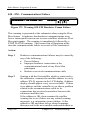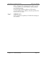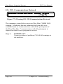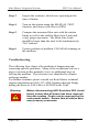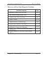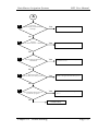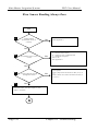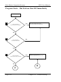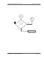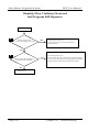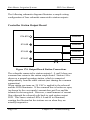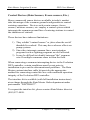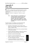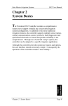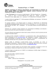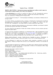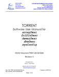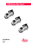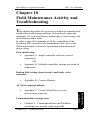
1
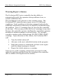
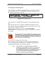
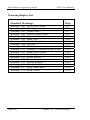
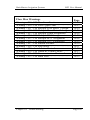
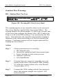
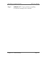
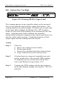
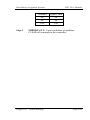
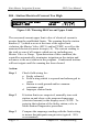
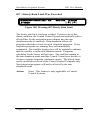
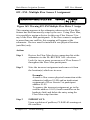
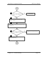
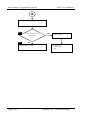
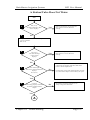
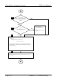
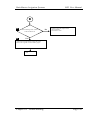
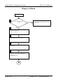
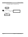
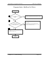
Rain Master Irrigation Systems
DX2 User Manual
Chapter 10
Field Maintenance Activity and
Troubleshooting
This chapter describes the resources available to maintain and
troubleshoot field wiring problems, broken heads, pipes and
mainlines, AC power problems, monitoring of water usage, and
miscellaneous other items.
In order to take full advantage of all the capabilities of the
Evolution DX2 controller as a maintenance tool, refer to the
following manual sections for operational information and
proper setup:
Flow monitoring:
•
Appendix A: Single controller with one point of
connection
OR
•
Appendix E: Multiple controllers sharing one point of
connection
Broken field wiring, short circuits, and faulty valve
solenoids:
•
Appendix B: Current Monitor
Appendix C: Power Failure/Recovery (no
special setup required)
Communications wiring issues:
•
Chapter 9: Communications and Problem
reporting (no special setup required)
Chapter 10: Troubleshooting
Chapter 10:
•
Troubleshooting
AC Power input problems:
Page 161
Rain Master Irrigation Systems
DX2 User Manual
Warning Report (Alarms)
The Evolution DX2 series controller has the ability to
automatically notify the operator when problems occur, or
certain conditions arise.
The mechanism used is known as the warning report. The
Evolution DX2 controller may report on over 30 different
conditions. Each condition is date/time stamped and includes
additional information which may be helpful in troubleshooting
the problem. Up to 15 warnings may be saved in the controller
at one time. The user may delete the list of warnings at any time.
Because the controller operates intelligently, immediate operator
attention to alarms/warnings is not necessary. For example,
consider a station with a broken head (FLOW UPPER LIMIT
warning). Upon detection of this failure, the Evolution DX2
will:
•
Turn the failed station off
•
Advance to the next scheduled station in the program
•
Mark this station as condemned (will not water again
until the alarm/warning is cleared)
•
Report the failed station as a warning
Upon review of the warning, maintenance personnel would
repair the problem and then clear the warning at the controller
(this re-enables all irrigation at the station).
Page 162
Chapter 10: Troubleshooting
Rain Master Irrigation Systems
DX2 User Manual
Viewing the Warning List
Any time that a warning is generated by the controller, the base
screen displays the F 2 =WARNING message as illustrated in
the following base menu display:
WED 02:10:57PM VALID PGM: 1
06/05/96 WK1
|F1|=MAIN MENU |F2|=WARNING
Figure 141: Base Screen
Selecting the F2=WARNING displays the first problem in the
list.
Press the Down Arrow to display additional problems, if any.
Press the Up Arrow to display problems previously listed, if any,
and to move to the base screen.
After the last problem, press F1 =CLEAR REPORT
MESSAGES to Clear Report Messages. All problems in the list
are erased.
Warning:
Pressing the F1 key deletes all messages from
the list. The messages cannot be recovered. Do
not select F1 if you wish to continue reviewing
the current list of problems.
Press QUIT to return to the base menu.
The remainder of this chapter provides detailed information
about each warning, possible causes, and most important, the
recommended actions for problem solutions.
Note:
The following warning illustrations include a
numbering system (001-032) which corresponds to
the warning number sequence generated in the
Central Control Computer. This numbering system
may be disregarded in installations that do not
include a Central Control Computer.
Chapter 10: Troubleshooting
Page 163
Rain Master Irrigation Systems
DX2 User Manual
Warning Display List
Standard Warnings
Page
Warning = 001 -Flow Lower Limit……...….……....
Warning = 002 -Flow Upper Limit…………………
Warning = 003 -Water Limit………………………..
Warning = 004 -Current Upper Limit……………....
Warning = 005 -Current Low Limit………………....
Warning = 006 -Main Flow…………………………
Warning = 007 -Hourly Rain Limit………………....
Warning = 008 -On Line………………………...….
Warning = 009 -Off line…..………………………...
Warning = 010 -Hardwire Communication Failure...
Warning = 011 -Wind Lower Limit………………..
Warning = 012 -Wind Upper Limit……….………..
Warning = 013 -Power Failure………………..........
Warning = 014 -Power On……………..………..….
Warning = 015 -Upload Request……………….…..
Warning = 016 -Unscheduled Limit………………...
Warning = 017 -Daily Rain Limit……..…….….…..
Warning = 018 -Short Circuit…………………….…
10-5
10-6
10-7
10-8
10-9
10-10
10-11
10-12
10-13
10-14
10-15
10-16
10-17
10-17
10-18
10-19
10-20
10-21
Page 164
Chapter 10: Troubleshooting
Rain Master Irrigation Systems
DX2 User Manual
Flow Max Warnings
Page
Warning = 019 - FM Flow Low Limit……..……........
Warning = 020 - FM Flow Upper Limit……….……...
Warning = 021 - FM Multiple Flow Meter 1 Assign….
Warning = 022 - FM Multiple Flow Meter 2 Assign….
Warning = 023 - FM Multiple Pump Assignment…….
Warning = 024 - FM Multiple MV1 Assignment..……
Warning = 025 - FM Multiple MV2 Assignment………
Warning = 026 - FM Multiple N.O. Assignment……...
Warning = 027 - FM Station Advance .……………….
Warning = 028 - FM Stop Water…………………….…
Warning = 029 - Auto Limits Aborted..….……...........
Warning = 030 - FM Hardwire Comm Failure………..
Warning = 031 - FM Communications Restored……...
Warning = 032 - FM Main Flow…………..….……….
10-22
10-23
10-24
10-25
10-26
10-27
10-28
10-29
10-30
10-31
10-32
10-33
10-34
10-35
Chapter 10: Troubleshooting
Page 165
Rain Master Irrigation Systems
DX2 User Manual
Standard Flow Warnings
001 - Station Flow Too Low
WARNING = FLOW LOW LIMIT 06/20/96 10:45AM
STA=2, MV1
GPM=12 |¾||½|
Figure 142: Warning 001 -Flow Lower Limit
This warning appears at any controller whenever the measured
flow is less than the expected flow (lower limit failure). The
warning displays the station number (2) which was on at the time
of the lower limit violation, the Master Valve (MV1) and/or the
Pump, as well as the GPM reading (12) as measured by the flow
meter. Upon detection, the controller automatically terminates
irrigation on the station and advances to the next station in the
program. Condemned stations will not irrigate again until the
warning has been cleared.
Action:
Step 1
Alarm generation may be caused by:
a. Mis-adjusted valve
b. Incorrectly established individual station limits
c. Large variations in static water pressure
d. Improper regulation
e. Line impediments
Step 2
If station limits are suspected, manually turn each
station on and observe the nominal GPM readings.
To isolate the suspect station, refer to the Manual
Test procedure, (8-2).
Step 3
Compare the GPM reading with the limit setting to
insure that adequate margin exits (typical: 50%
below nominal).
Page 166
Chapter 10: Troubleshooting
Rain Master Irrigation Systems
Step 4
DX2 User Manual
IMPORTANT: Upon resolution of problem,
CLEAR all warnings at the controller.
Chapter 10: Troubleshooting
Page 167
Rain Master Irrigation Systems
DX2 User Manual
002 - Station Flow Too High
WARNING = FLOW UP LIMIT 06/20/96
STA=2, MV1
GPM=90
10:45AM
|¾||½|
Figure 143: Warning 002-Flow Upper Limit
This warning appears at any controller whenever the measured
flow is more than the expected flow (upper limit failure). The
warning displays the station number (2) which was on at the time
of the upper limit violation, the Master Valve (MV1) and/or
Pump, as well as the GPM reading (90) as measured by the flow
meter. Upon detection of this condition, the controller
automatically terminates irrigation on the station and advances to
the next station in the program. Condemned stations will not
irrigate again until the warning has been cleared.
Action:
Step 1
Check for:
a. Stuck valve (from previous station)
b. Broken pipes/heads
c. Incorrectly established individual station limits
d. Large variations in system water pressure
Step 2
If station limits are suspected, manually turn each
station on and observe the nominal GPM readings.
To manually turn on a station and read the flow,
refer to the Manual Test procedure, (8-2)
Step 3
Compare the GPM reading with the limit setting to
insure that adequate margin exits (typical: 20% over
nominal)
Page 168
Chapter 10: Troubleshooting
Rain Master Irrigation Systems
Nominal
50
80
100
Step 4
DX2 User Manual
Upper Limit
60
96
120
IMPORTANT: Upon resolution of problem,
CLEAR all warnings at the controller.
Chapter 10: Troubleshooting
Page 169
Rain Master Irrigation Systems
DX2 User Manual
003 - Monthly Water Limit Violation
WARNING = WATER LIMIT
STA=1,
06/20/96 09:05PM
|¾||½|
Figure 144: Warning 003-Water Limit
The controller has exceeded its monthly watering allocation. If
the program has been set up to stop watering, no further
irrigation will occur until day one of the next month. If the
program has been set up to provide a warning only, and the
alarm is cleared, then this warning will re-appear (watering
continues).
When the option is set to "Stop Watering" and the limit is
reached, the following action indicates how the warning can be
circumvented so that irrigation may continue:
Action:
Step 1 The limit can be increased at the controller
by entering:
F1=MAIN MENU
F5=SETUP
F4=CONTROLLER
F1=FLOW OPTIONS
F1=MONTHLY LIMIT
Then enter a new monthly limit: OR
Step 2 The limit may be set to NONE, at the controller by
entering:
Page 170
Chapter 10: Troubleshooting
Rain Master Irrigation Systems
DX2 User Manual
F1=MAIN MENU
F5=SETUP
F4=CONTROLLER
F1=FLOW OPTIONS
F1=MONTHLY LIMIT
Select F1=NONE to disable monthly water total
validation.
Step 3
IMPORTANT: Upon resolution of problem,
CLEAR all warnings at the controller.
Chapter 10: Troubleshooting
Page 171
Rain Master Irrigation Systems
DX2 User Manual
004 - Station Electrical Current Too High
WARNING = I UP LIMIT
STA=17, MV1
06/20/96
02:42PM
I=0.40
|¾||½|
Figure 145: Warning 004-Current Upper Limit
The measured current upper limit value of electrical current is
greater than the established limits. The warning lists the station
number (17) which was on at the time of the upper limit
violation, the Master Valve (MV1) and/or PUMP, as well as the
measured electrical current in amps (.4). The current reading is
the total or sum of all outputs which are on, including any
Master Valve or Pump. Upon detection of this condition, the
controller automatically terminates irrigation on the station and
advances to the next station in the program. Condemned stations
will not irrigate until the warning has been cleared.
Action:
Step 1
Check field wiring for:
a. Faulty solenoid
b. Field wiring which is exposed and submerged in
water
c. Station to earth ground and/or common
resistance path
d. Improper station limits
Step 2
If station limits are suspected, manually turn each
station on and observe the measured amperage
(electrical current) in the display area I=X.XX. To
assist in the isolation of the faulty station, refer to
Multi-Station Diagnostics procedure.
Step 3
Compare the amperage reading with the limit setting
to insure that adequate margin exits (typical: 20%
over nominal).
Page 172
Chapter 10: Troubleshooting
Rain Master Irrigation Systems
Step 4
DX2 User Manual
IMPORTANT:
Upon resolution of problem, CLEAR all warnings at
the controller.
Chapter 10: Troubleshooting
Page 173
Rain Master Irrigation Systems
DX2 User Manual
005 - Station Electrical Current Too Low
WARNING = I LOW LIMIT
06/20/96
03:15PM
STA=5
I=0.00
|¾||½|
Figure 146: Warning 005-Current Low Limit
The measured current lower limit value of electrical current is
less than the established limits. The warning lists the station
number (5) which was on at the time of the lower limit violation,
the Master Valve and/or Pump, as well as the measured electrical
current in amps (0.00). The current reading is the total or sum of
all outputs which are on. Upon detection of this condition, the
controller automatically terminates irrigation on the station and
advances to the next station in the program. Condemned stations
will not irrigate again until the warning has been cleared.
Action:
Step 1
Check field wiring for:
a. Faulty solenoid (open coil)
b. No station connection at terminal output board
c. Improper field wire connections at valve solenoid
d. Poor common connection in field wiring
e. Improper station limits
Step 2
If station limits are suspected, manually turn each
station on and observe the measured amperage
(electrical current) in the display area I=X.XX.
(Refer to Multi-Station Diagnostics procedure.)
Step 3
Compare the amperage reading with the limit setting
to insure that adequate margin exists (typical: 50%
under nominal).
Page 174
Chapter 10: Troubleshooting
Rain Master Irrigation Systems
Step 4
DX2 User Manual
IMPORTANT:
Upon resolution of problem, CLEAR all warnings at
the controller.
Chapter 10: Troubleshooting
Page 175
Rain Master Irrigation Systems
DX2 User Manual
006 - Controller Main Line Break Occurred
WARNING = MAIN FLOW (MV)
06/20/96 10:46PM
STA=7, MV1
GPM=220
|¾||½|
Figure 147: Warning 006-Main Flow
The maximum main line break flow rate was exceeded for the
controller. The warning lists the station number (7) which was
on at the time the controller Main Line Limit failure occurred as
well as the measured flow in GPM (220). All irrigation for the
controller is immediately terminated. In addition, the Normally
Open Master Valve terminal (N.O.) is energized with 24 VAC.
Any and all future automatic irrigation will not occur until this
warning is cleared from the controller.
Action:
Step 1
Inspect the main line as well as major branches for
failure.
Step 2
Inspect the station(s) which were operating at the
time of the failure.
Step 3
Turn on the station by using the Manual Test
function, and observe the flow in GPM.
Step 4
Compare the measured flow rate with the station
limits as well as the controller Main Line Limit and
verify proper operation. The Main Line Limit
should be larger than the total of all simultaneously
"On" stations.
Step 5
Upon resolution of problem, CLEAR all warnings at
the controller.
Page 176
Chapter 10: Troubleshooting
Rain Master Irrigation Systems
DX2 User Manual
007 - Hourly Rain Limit Was Exceeded
WARNING = RAIN LIMIT- HR
.07 INCH
06/21/96 12:46PM
|¾||½|
Figure 148: Warning 007-Hourly Rain Limit
The hourly rain limit has been reached. Upon receipt of this
alarm condition, the Central Control System automatically places
all satellites for the associated microclimate into the rain
shutdown mode (if enabled). Rain shutdown affects all
programs which have been set up as irrigation programs. If any
irrigation programs are running, they are immediately
terminated. The satellite display area will be updated to indicate
that the satellite is in the rain shutdown mode. Programs
scheduled for the future will not start. The satellites remain in
the rain shutdown mode until the Central Control user decides it
is time to resume irrigation (automatic mode). The hourly limit
can be modified/reviewed at the Central Control Computer only.
Non irrigation programs will not be affected by the rain
shutdown mode.
Action:
None. This feature is only applicable to Central
Control Systems.
Chapter 10: Troubleshooting
Page 177
Rain Master Irrigation Systems
DX2 User Manual
008 - Hardwire Communications Restored (On Line)
WARNING = ON LINE
03/20/93
04:36PM
|¾||½|
Figure 149: Warning 008-On Line
A satellite has restored hardwire communications with its
submaster. Upon restoration of communications, the satellite
displays its address in the LCD display area. This message is
only applicable when the satellite is using a hardwire
communications line between itself and the submaster. This
warning may be preceded by an OFFLINE warning which
indicates when the hardwire communications were lost.
Note:
The submaster automatically attempts to initiate as
well as maintain hardwire communications at all
times.
Action:
Step 1
Page 178
Clear the warning at the satellite.
Chapter 10: Troubleshooting
Rain Master Irrigation Systems
DX2 User Manual
009 - Off Line
WARNING = OFF LINE
03/20/93 04:30PM
|¾||½|
Figure 150: Warning 009-Off line
A satellite has lost hardwire communications with its submaster.
Hardwire communications occur between the submaster and its
satellites at the rate of once every 0.1 seconds. Loss of
communications may be temporary (power glitch) or permanent
(severed EV-CAB-COM communications cable). In either case,
irrigation will continue at the satellites without interruption as
long as the configuration does not utilize the Flow Max feature.
This message will be accompanied by a corresponding message
at its submaster, "HW COMM FAILURE."
Action:
Step 1
Hardwire communications failures may be caused by
any of the following: power failures, improper
hardwire connections at the communications board,
or broken/severed communications cable.
Step 2
Starting with the first satellite which is connected to
the submaster, examine the satellite address to verify
address XX-01 appears in the LCD display. If there
is no address and the controller is on, then a problem
related to the communications cable or its
connections has occurred somewhere between the
submaster and this unit. If the address is OK,
examine the satellite warning list for any related
warning messages, e.g. momentary power failure. If
address is OK and there are no related warnings,
proceed to the next satellite and troubleshoot as
above. Because the communications cable is wired
Chapter 10: Troubleshooting
Page 179
Rain Master Irrigation Systems
DX2 User Manual
to each satellite in series, cable problems are isolated
quickly.
If the previous satellite's address is OK but the
current satellite has no address, the problem lies
between the two units.
Step 3
Page 180
IMPORTANT:
Upon resolution of problem, CLEAR all warnings at
the satellites.
Chapter 10: Troubleshooting
Rain Master Irrigation Systems
DX2 User Manual
010 - Hardwire Communication Failure
WARNING = HW COMM FAIL
03/20/93 04:30PM
|¾||½|
Figure 151: Warning 010-Hardwire Communication Failure
A submaster has lost hardwire communications comm. with one
or more satellites. Hardwire communications occur between the
submaster and its satellites at the rate of once every 0.1 seconds.
Loss of communications may be temporary (power glitch) or
permanent (severed EV-CAB-COM communications cable). In
either case, irrigation will continue at the satellites without
interruption as long as the configuration does not utilize the Flow
Max feature. This message will be accompanied by a
corresponding message at one or more satellites, "OFFLINE."
Action:
Step 1
Hardwire communications failures may be caused by
any of the following: power failures, improper
hardwire connections at the communications board,
or broken/severed communications cable.
Step 2
Starting with the first satellite which is connected to
the submaster examine the satellite address to verify
address XX-01 appears in the LCD display. If there
is no address and the controller is on, then a problem
related to the communications cable or its
connections has occurred somewhere between the
submaster and this unit. If the address is OK,
examine the satellite warning list for any related
warning messages, e.g. momentary power failure. If
address is OK and there are no related warnings,
proceed to the next satellite and troubleshoot as
above. Because the communications cable is wired
Chapter 10: Troubleshooting
Page 181
Rain Master Irrigation Systems
DX2 User Manual
to each satellite in series, cable problems are isolated
quickly.
If the previous satellite's address is OK but the
current satellite has no address, the problem lies
between the two units.
Step 3
Page 182
IMPORTANT:
Upon resolution of problem, CLEAR all warnings at
the satellites.
Chapter 10: Troubleshooting
Rain Master Irrigation Systems
DX2 User Manual
011 - Wind Lower Limit Satisfied
WARNING = WIND LOW LIMIT
5 MPH FOR 2 MIN
06/21/93 02:30PM
|¾||½|
Figure 152: Warning 011-Wind Lower Limit
The lower wind limit condition has been satisfied. Upon receipt
of this alarm condition, the Central Control System
automatically removes all satellites from wind shutdown mode
(only those satellites within the confines of the wind
microclimate are affected). Once removed from wind shutdown mode, the satellite (s) resume any program execution by
enabling any station outputs which may be required.
Note:
Action:
Programs which were in wind shutdown mode are
not suspended in time. All programs continue to
run as normal with the exception that their outputs
(stations, MV's and Pump) are not active. Wind
limits can be modified and reviewed at the Central
Control Computer only.
None. This feature is only applicable to Central
Control Systems.
Chapter 10: Troubleshooting
Page 183
Rain Master Irrigation Systems
DX2 User Manual
012 - Wind Upper Limit Exceeded
WARNING = WIND UP LIMIT
22 MPH FOR 2 MIN
06/21/96
12:30PM
|¾||½|
Figure 153: Warning 012-Wind Upper Limit
The wind upper limit has been reached. Upon receipt of this
alarm condition, the Central Control System automatically places
all satellites into the wind shutdown mode (only those satellites
within the confines of the wind microclimate are affected).
Programs which are running at the time the satellite goes into
wind shutdown mode automatically turn all outputs off (stations,
Master Valves, Pumps, etc.). These programs however, continue
to advance in time and will resume if the wind lower limit
conditions have been met. Wind limits can be modified and
reviewed at the Central Control Computer only.
Action:
Page 184
None. This feature is only applicable to Central
Control Systems.
Chapter 10: Troubleshooting
Rain Master Irrigation Systems
DX2 User Manual
013 - Power Failure
WARNING = POWER FAILURE
01/01/92 08:30PM
|¾||½|
Figure 154: Warning 013-Power Failure
The AC power to the controller has been lost. Power failures
may occur due to any of the following:
•
•
•
Turning the AC switch off at the controller
Power glitches or outages from the power company
Improper AC connections at the controller or main
distribution point
Action:
Step 1
Infrequent minor interruptions in power from the
power company may be a common occurrence, and
therefore no action is required.
Step 2
If power interruptions occur frequently, (several
times per week) it may be indicative of an improper
AC wiring connection to the controller, or improper
service from the power company.
Step 3
If power is out for an extended time, then the user
may wish to schedule supplemental irrigation.
Step 4
IMPORTANT:
Upon resolution of problem, CLEAR all warnings at
the satellites.
Chapter 10: Troubleshooting
Page 185
Rain Master Irrigation Systems
DX2 User Manual
014 - Power Restoration
WARNING = POWER ON
01/01/92
08:30PM
|¾||½|
Figure 155: Warning 014-Power On
The AC power to the controller has been returned. This alarm is
automatically generated by the controller upon detection of its
AC input power.
Action:
Step 1
Page 186
Clear the warning at the controller.
Chapter 10: Troubleshooting
Rain Master Irrigation Systems
DX2 User Manual
015 - Program Upload Request
WARNING = PROGRAM UPLOAD 10/30/96 04:21PM
PGM=5 |¾||½|
Figure 156: Warning 015-Upload Request
The user has requested the Central Control System to upload a
specific program.
"PGM=" designates the program number.
Warning:
Action:
Uploading a program from the satellite to Central
Control System should not be performed if the
user is utilizing BASIC ET at this satellite. An
upload in this instance would overwrite the
BASE schedule at central with a field satellite
program which has adjusted ET runtimes.
None. This feature is only applicable to Central
Systems.
Chapter 10: Troubleshooting
Page 187
Rain Master Irrigation Systems
DX2 User Manual
016 - Unscheduled Flow
WARNING = UNSCHEDULED LIMIT 08/27/92 12:05AM
GPM=40 |¾||½|
Figure 157: Warning 016-Unscheduled Limit
Flow was detected but the controller had no programs or manual
stations running. The flow sensor however recorded unexpected
flow "GPM=40." The controller will energize the N.O. Master
Valve output. All future scheduled irrigation will be inhibited
until this alarm has been cleared at the controller.
Action:
Step 1
Check for leaks, broken pipe(s), or physical damage.
Step 2
It is possible that a stuck valve from a previous
scheduled irrigation caused the failure. Check for
stuck valves.
Step 3
It is possible that the limit has been improperly
established. If quick coupling devices were on at the
time the alarm occurred, insure that there are enough
margins for the unscheduled flow limit. Refer to
section of Unscheduled Flow Limit.
Step 4
IMPORTANT:
Upon resolution of problem, CLEAR all warnings at
the satellites.
Page 188
Chapter 10: Troubleshooting
Rain Master Irrigation Systems
DX2 User Manual
017 - Daily Rain Limit Reached
WARNING = RAIN LIMIT- DAY
0.16 INCH
06/21/96 12:05PM
|¾||½|
Figure 158: Warning 017-Daily Rain Limit
The daily rain limit has been reached. Upon receipt of this alarm
condition, the Central Control System automatically places all
satellites for the associated microclimate into the rain shutdown
mode (if enabled). Rain shutdown affects all programs which
have been set up as irrigation programs. If any irrigation
programs are running, they are immediately terminated. The
satellite display area will be updated to indicate that the satellite
is in the rain shutdown mode. Programs scheduled for the future
will not start. The satellites remain in the rain shutdown mode
until the Central Control user decides it is time to resume
irrigation (automatic mode). Rain limits can be modified and
reviewed at the Central Control Computer only. Non irrigation
programs will not be affected by the rain shutdown mode.
Action:
None. This feature is only applicable to Central
Control Systems.
Chapter 10: Troubleshooting
Page 189
Rain Master Irrigation Systems
DX2 User Manual
018 - Short Circuit
WARNING = SHORT CIRCUIT
STA = PUMP, MV1, 1
06/20/96
05:15PM
|¾||½|
Figure 159: Warning 018-Short Circuit
A short circuit problem was detected on a station or device. The
warning screen displays the stations and devices that were on at
the time of short circuit detection. This alarm will occur whether
or not station limits have been enabled or disabled. Upon
detection, the controller immediately turns the station(s) off and
advances to the next station in the program. This insures that no
physical damage occurs to the controller by drawing too much
current.
Action:
Step 1
Too much current for a station is caused by improper
field wiring or valve solenoid failure.
a. Examine the station field wiring and look for an
inadvertent connection from the station field
wire directly to the controller common
b. Look for a direct connection from the station
field wire to earth ground
c. Look for a shorted solenoid in the valve
d. For warnings displaying multiple stations,
identify the defective station/device using the
Multi-Station Diagnostics procedure
Step 2
Page 190
IMPORTANT:
Upon resolution of problem, CLEAR all warnings at
the satellites.
Chapter 10: Troubleshooting
Rain Master Irrigation Systems
DX2 User Manual
Flow Max Warnings
019 - Flow Max - Flow Lower Limit Violation
WARNING = FM FLOW LO LIM
05/30/96 04:45PM
SAT = 1, 4, 5
GPM=90
|¾||½|
Figure 160: Warning 019-FM Flow Low Limit
This warning appears FM flow lower limit at the submaster
whenever the measured flow is less than the expected flow
(lower limit failure). "SAT=" lists the address(es) of any
satellites which were irrigating at the time of the warning.
Example: Assume a submaster address of 35-00.
If the warning reads "SAT=1, 4, 5 GPM=90" then
each of the satellites 35-01, 35-04, 35-05 had one or
more stations which were on. Their combined
measured flow was 90 GPM which is less than the
programmed limit.
Action:
Step 1
Examine the warnings at the listed satellites to
determine which stations were on at the time of the
warning. Stations can be identified by viewing the
"FM STATION ADVANCE" warning at each of the
satellites.
Step 2
Alarm generation may be caused by mis-adjusted
valves, incorrectly established individual station
limits, large variations in static water pressure,
improper regulation, or line impediments.
Step 3
If station limits are suspected, manually turn each
station on and verify the lower limits. To manually
Chapter 10: Troubleshooting
Page 191
Rain Master Irrigation Systems
DX2 User Manual
turn on a station and read the flow, refer to the
Manual Test procedure.
Step 4
Page 192
IMPORTANT:
Upon resolution of the problem, CLEAR all
warnings at all satellites. If warnings are not
cleared, the stations will remain off indefinitely.
Chapter 10: Troubleshooting
Rain Master Irrigation Systems
DX2 User Manual
020 - Flow Max - Flow Upper Limit Violation
WARNING = FM FLOW UP LIM 05/30/96 04:45PM
SAT = 2, 5,
GPM=420 |¾||½|
Figure 161: Warning 020-FM Flow Upper Limit
This warning appears at the submaster whenever the measured
flow is more than the expected flow (upper limit failure).
"SAT=" lists the address(es) of any satellites which were
irrigating at the time of the warning.
Example: Assume a submaster address of 01-00. If the warning
reads "SAT=2,5 GPM=420" then satellites 01-02,
01-05 had irrigating stations and the sum of their
measured flow was 420 GPM.
Action:
Step 1
Examine the warnings at the listed satellites to
determine which stations were on at the time of the
warning. Each satellite will have an "FM STATION
ADVANCE" warning. This warning indicates
which stations were on at the time the submaster
detected the "FLOW UP LIM" violation.
Step 2
Check for:
a. Stuck valve (from previous station)
b. Broken pipes/heads
c. Incorrectly established individual station limits
d. Large variations in system water pressure
Step 3
IMPORTANT:
Upon resolution of the problem, CLEAR all
warnings at all satellites. If warnings are not
cleared, the stations will remain off indefinitely.
Chapter 10: Troubleshooting
Page 193
Rain Master Irrigation Systems
DX2 User Manual
021 - FM - Multiple Flow Sensor 1 Assignment
WARNING = MULTIPLE FM 1
06/14/96
11:45AM
|¾||½|
Figure 162: Warning 021-FM Multiple Flow Meter 1 Assign
This warning appears at the submaster whenever the Flow Max
feature has been incorrectly set up by the user. Using Flow Max,
it is possible to assign a device (in this case Flow Sensor 1) to
any of the Flow Max participants. If the user makes an error by
assigning the flow sensor to more than one satellite, this warning
will appear at the submaster. Devices must be installed at one
physical location (controller) only.
Action:
Step 1
Review the Flow Max device connection list at the
via the F4=REVIEW ALL selection. Look for two
or more occurrences of Flow Sensor 1 throughout
the Flow Max participants.
Step 2
Note the incorrect assignment and remove it from
the location(s), which are in error.
Example:
Assume a flow sensor physical connection at the
submaster (address 01-00) and an inadvertent
assignment of Flow Sensor 1 at participant address
01-02.
To remove the incorrect assignment, go to the
satellite address 01-02 (third controller on the
hardwire link) and delete the entry using the
Flow Max setup function.
Step 3
Page 194
IMPORTANT:
Upon resolution of problem, CLEAR all warnings at
the satellites.
Chapter 10: Troubleshooting
Rain Master Irrigation Systems
DX2 User Manual
022 - FM - Multiple Flow Sensor 2 Assignment
WARNING = MULTIPLE FM 2
06/14/96 11:45AM
|¾||½|
Figure 163: Warning 022-FM Multiple Flow Meter 2 Assign
This warning appears at the submaster whenever the Flow Max
feature has been incorrectly setup by the user. Using Flow Max,
it is possible to assign a device (in this case Flow Sensor 2) to
any of the Flow Max participants. If the flow sensor is assigned
to more than one satellite, this warning will appear at the
submaster. Devices must be installed at one physical location
(satellite) only.
Action:
Step 1
Review the Flow Max device connection list at the
submaster via the F4=REVIEW ALL selection.
Look for two or more occurrences of Flow Sensor 2
throughout the Flow Max participants.
Step 2
Note the incorrect assignment and remove it from
the location(s) which are in error.
Example:
Assume a flow sensor physical connection at the
submaster (address 01-00) and an inadvertent
assignment of Flow Sensor 2 at participant
address 01-03.
To remove the incorrect assignment, go to the
satellite address 01-03 (fourth controller on the
hardwire link) and delete the entry using the
Flow Max setup function.
Step 3
IMPORTANT:
Upon resolution of problem, CLEAR all warnings at
the satellites.
Chapter 10: Troubleshooting
Page 195
Rain Master Irrigation Systems
DX2 User Manual
023 - FM - Multiple Pump Assignment
WARNING = MULTIPLE PUMP
06/14/96
11:30PM
|¾||½|
Figure 164: Warning 023-FM Multiple Pump
This warning appears at the submaster whenever the Flow Max
feature has been incorrectly set up by the user. Using Flow Max,
it is possible to assign a device (in this case the Pump) to any of
the Flow Max participants. If the Pump is assigned to more than
one controller, this warning will appear at the submaster.
Devices must be installed at one physical location (satellite)
only.
Action:
Step 1
Review the Flow Max device connection list at the
submaster via the F4=REVIEW ALL selection.
Look for two or more occurrences of the Pump
throughout the Flow Max participants.
Step 2
Note the incorrect assignment and remove it from
the location(s) which are in error.
Example:
Assume the pump's physical connection is at the
submaster (address 01-00) and the pump was
inadvertent assigned to the participant at address
01-03.
To correct this assignment, go to satellite
address 01-03 (fourth controller on the hardwire
link) and delete the entry using the Flow Max
setup function.
Page 196
Chapter 10: Troubleshooting
Rain Master Irrigation Systems
DX2 User Manual
Step 3 IMPORTANT:
Upon resolution of problem, CLEAR all warnings at the
satellites.
Chapter 10: Troubleshooting
Page 197
Rain Master Irrigation Systems
DX2 User Manual
024 - FM - Multiple Master Valve 1 Assignment
WARNING = MULTIPLE MV1
05/30/96
04:45PM
|¾||½|
Figure 165: Warning 024-FM Multiple MV1 Assignment
This warning appears at the submaster whenever the Flow Max
feature has been incorrectly set up by the user. Using Flow Max,
it is possible to assign a device (in this case Master Valve 1) to
any of the Flow Max participants. If Master Valve 1 is assigned
to more than one satellite, this warning will appear at the
submaster. Devices must be installed at one physical location
(controller) only.
Action:
Step 1
Step 2
Review the Flow Max device connection list at the
submaster via the F4=REVIEW ALL selection.
Look for two or more occurrences of Master Valve 1
throughout the Flow Max participants.
Note the incorrect assignment and remove it from
the location(s) which are in error.
Example:
Assume the Master Valve physical connection is
at submaster (address 01-00) and the Master
Valve was inadvertent assigned to participant
address 01-02.
To remove the incorrect assignment, go to the
satellite address 01-02 (third controller on the
hardwire link) and delete the entry using the
Flow Max setup function.
Step 3
Page 198
IMPORTANT:
Upon resolution of problem, CLEAR all warnings at
the satellites.
Chapter 10: Troubleshooting
Rain Master Irrigation Systems
DX2 User Manual
025 - FM - Multiple Master Valve 2 Assignment
WARNING = MULTIPLE MV2
06/03/96
06:45PM
|¾||½|
Figure 166: Warning 025-FM Multiple MV2 Assignment
This warning appears at the submaster whenever the Flow Max
feature has been incorrectly set up by the user. Using Flow Max,
it is possible to assign a device (in this case Master Valve 2) to
any of the Flow Max participants. If Master Valve 2 is assigned
to more than one satellite, this warning will appear at the
submaster. Devices must be installed at one physical location
(satellite) only.
Action:
Step 1
Review the Flow Max device connection list at the
submaster via the F4=REVIEW ALL selection.
Look for two or more occurrences of Master Valve 2
throughout the Flow Max participants.
Step 2
Note the incorrect assignment and remove it from
the location(s) which are in error.
Example:
Assume the Master Valve physical connection is
at submaster (address 01-00) and the Master
Valve was inadvertent assigned to participant
address 01-03.
To remove the incorrect assignment, go to the
satellite address 01-03 (fourth controller on the
hardwire link) and delete the entry using the
Flow Max setup function.
Chapter 10: Troubleshooting
Page 199
Rain Master Irrigation Systems
Step 3
Page 200
DX2 User Manual
IMPORTANT:
Upon resolution of problem, CLEAR all warnings at
the satellites.
Chapter 10: Troubleshooting
Rain Master Irrigation Systems
DX2 User Manual
026 - FM - Multiple Normally Open Master Valves
WARNING = MULTIPLE N.O.
06/03/96
06:45PM
|¾||½|
Figure 167: Warning 026 -FM Multiple N.O. Assignment
This warning appears at the submaster whenever the Flow Max
feature has been incorrectly set up by the user. Using Flow Max,
it is possible to assign a device (in this case the Normally Open
Master Valve) to any of the Flow Max participants. If the user
makes an error by assigning the N.O. MV to more than one
satellite, this warning will appear at the submaster. Devices
must be installed at one physical location (satellite) only.
Action:
Step 1
Review the Flow Max device connection list at the
submaster via the F4=REVIEW ALL selection.
Look for two or more occurrences of the N.O. MV
throughout the Flow Max participants.
Step 2
Note the incorrect assignment and remove it from
the location(s) which are in error.
Example:
Assume a N.O. MV physical connection is at
submaster (address 01-00) and the N.O. MV was
inadvertent assigned to participant address 0103.
To remove the incorrect assignment go to the
satellite address 01-03 (fourth controller on the
hardwire link) and delete the entry using the
Flow Max setup function.
Chapter 10: Troubleshooting
Page 201
Rain Master Irrigation Systems
Step 3
Page 202
DX2 User Manual
IMPORTANT:
Upon resolution of problem, CLEAR all
warnings at the satellites.
Chapter 10: Troubleshooting
Rain Master Irrigation Systems
DX2 User Manual
027 - Flow Max - Station Advance
WARNING = FM STA ADVANCE
STA= 1,
05/30/96 04:45PM
|¾||½|
Figure 168: Warning 027-FM Station Advance
This warning is issued to all Flow Max participants who have
stations on whenever either a FLOW UP LIM or a FLOW LO
LIM Warning (upper or lower limit failure) has occurred. The
"STA=" information indicates which stations were on at the time
the flow violation occurred. Upon receipt of this command, the
satellite will terminate irrigation for the listed stations and
automatically advance to the next station in the current program.
Future irrigation will not occur at the listed stations until this
alarm is CLEARED from the satellite/s.
Action:
Step 1
Review the Action information listed under the
FLOW UP LIM or the FLOW LO LIM warnings.
Step 2
Investigate individual station operation for listed
stations. (Refer to the Manual Test procedure)
Manually turn on each station individually and
visually inspect operation. Note the measured flow
readings and compare to both the upper and lower
limits which are set for this station. Check for any
broken or restricted heads, etc.
Step 3
IMPORTANT:
Upon resolution of problem, CLEAR all warnings at
the satellites.
Chapter 10: Troubleshooting
Page 203
Rain Master Irrigation Systems
DX2 User Manual
028 - Flow Max - Stop Water
WARNING = FM STOP WATER
STA= PUMP, N.O., MV1,
06/14/96
10:45PM
|¾||½|
Figure 169: Warning 028 -FM Stop Water
This warning is originated by the submaster whenever flow
violations occur. It is sent to all Flow Max participants when
any of the following conditions occur:
• Unscheduled Flow
• Main Line Break
• Hardwire Communications Failure
• Power Failures
"STA=" indicates which stations were on at the time the
command was issued. Satellites which receive this warning
terminate all irrigation.
Action:
Step 1
Read the alarms at the submaster to determine the
reason for the alarm.
Step 2
Read the alarms at the satellites(s) for satellite
specific information.
Step 3
IMPORTANT:
Upon resolution of problem, CLEAR all warnings at
all satellites.
Page 204
Chapter 10: Troubleshooting
Rain Master Irrigation Systems
DX2 User Manual
029 - Auto Limits Aborted
WARNING = AUTO LIM ABORT
06/21/96
02:48PM
|¾||½|
Figure 170: Warning 029 -Auto Limits
The automatic calculation of the Auto Limits feature had to be
stopped due to a potentially hazardous over current situation at
this satellite. This warning only occurs when the Auto Limits
feature is running. This alarm may be preceded by a SHORT
CIRCUIT alarm, indicating the station with the short circuit
condition.
Action:
Step 1
Correct the short circuit (over current) condition at
the station. The problem station may be identified
by performing the Multi-Station Diagnostics
procedure.
Step 2
CLEAR all alarms.
Step 3
Re-run the AUTO LIMITS function.
Step 4
IMPORTANT:
Upon resolution of problem, CLEAR all warnings at
the satellites.
Chapter 10: Troubleshooting
Page 205
Rain Master Irrigation Systems
DX2 User Manual
030 - FM - Communications Failure
WARNING = FM COMM FAIL
05/30/96 04:45PM
|¾||½|
Figure 171: Warning 030 -FM Hardwire Comm Failure
This warning is generated at the submaster when using the Flow
Max feature. It indicates that hardwire communications were
lost or interrupted between one or more satellites which are Flow
Max participants. The warning is immediately followed by a
STOP WATER warning. This means that all irrigation at the
time the communications failure occurred will be terminated.
Action:
Step 1
Hardwire communications failures may be caused by
any of the following:
• Power failures
• Improper hardwire connections at the
communications board of any Flow Max
participant
• Broken or severed communications cable
Step 2
Starting with the first satellite which is connected to
the submaster, examine the satellite address to verify
address XX-01 appears in the LCD display (Address
display should appear every seven seconds). If there
is no address and the controller is on, then a problem
related to the communications cable or its
connections has occurred somewhere between the
submaster and this unit.
If the address is OK, then examine the satellite
warning list to see if there are any related warning
messages, e.g. momentary power failure. If the
address is OK and there are no related warnings,
then proceed to the next satellite and troubleshoot as
Page 206
Chapter 10: Troubleshooting
Rain Master Irrigation Systems
DX2 User Manual
above. Because the communications cable is wired
to each satellite in a serial fashion, cable problems
are isolated quickly.
If the previous satellites address is OK but the
current satellite has no address, then the problem lies
between the two units.
Step 3
IMPORTANT:
Upon resolution of problem, CLEAR all warnings at
the satellites.
Chapter 10: Troubleshooting
Page 207
Rain Master Irrigation Systems
DX2 User Manual
031- FM - Communications Restored
WARNING = COMM RESTORED
05/30/96 04:45PM
|¾||½|
Figure 172: Warning 031 -FM Communications Restored
This warning is issued after a previous Flow Max COMM FAIL
warning. It indicates that the submaster has been able to reestablish hardwire communications with all the participants of
the Flow Max link. Communications with all participants is
required in order for any program to execute.
Step 1:
Page 208
IMPORTANT:
Upon resolution of problem, CLEAR all warnings at
the satellites.
Chapter 10: Troubleshooting
Rain Master Irrigation Systems
DX2 User Manual
032 - Flow Max - Main Flow
WARNING = FM MAIN FLOW
SAT=2, 5,
06/14/96 10:45AM
|¾||½|
Figure 173: Warning 032 -FM Main Flow
This alarm appears at the submaster whenever the measured flow
is more than the Main Line Break Limit established at the
submaster. It indicates that the sum of water from all Flow Max
participants exceeds the Main Line Break Limit. The submaster
automatically issues a STOP WATER warning to all
participants, to insure that all irrigation at every satellite
terminates. The NORMALLY OPEN MV terminal will be
automatically energized at the submaster as well as at the shared
location. IMPORTANT: All future scheduled irrigation for any
of the Flow Max participants will not occur until this alarm has
been cleared at the satellite.
"SAT=" lists the address(es) of any satellites which were
irrigating at the time of the warning.
Example:
Assume a submaster address of 01-00. If the warning
reads "SAT =2,5 GPM=620" THEN satellites 01-02, 0105 had irrigating stations and the sum of their measured
flow was 620 GPM.
Action:
Step 1
Review the warnings at the listed satellites to
determine which stations were on at the time of the
warning.
Determine if any of these stations were responsible
for the Main Line Limit failure.
Step 2
Inspect the main line as well as major branches for
failure.
Chapter 10: Troubleshooting
Page 209
Rain Master Irrigation Systems
DX2 User Manual
Step 3
Inspect the station(s) which were operating at the
time of failure.
Step 4
Turn on the station using the MANUAL TEST
function, and observe the flow in GPM.
Step 5
Compare the measured flow rate with the station
limits as well as the satellite Main Line Limit and
verify proper operation. The Main Line Limit
should be larger than the total of all simultaneously
"On" stations.
Step 6
Upon resolution of problem, CLEAR all warnings at
the satellites.
Troubleshooting
The following flow charts offer methods of diagnosing and
correcting specific problems. Many of the resolutions refer to a
page or section in this manual to serve as additional steps in
solving the problem. The references are identified by chapter
and page number.
For further assistance please consult our Rain Master technical
support department at (805) 527-4498, Monday through Friday
during the hours of 8:00 AM to 5:00 PM Pacific Time.
Warning:
Page 210
Before disconnecting ANY Evolution DX2 circuit
board, ensure that all power has been removed
from the system. Power can be removed by the
main power switch. Ensure that all cables have
been properly connected.
Chapter 10: Troubleshooting
Rain Master Irrigation Systems
DX2 User Manual
Directory of Flow Chart Diagnostic Problems
Problem/Symptom
Page
Automatic Program Does Not Start
10-38
Flow Sensor Reading Always Zero
10- 40
A Station/Valve Does Not Water
10-43
Display is Blank
10- 46
Controller Emits a Constant Tone
10-48
Program Starts-But Does Not Water
10- 49
Program Starts-But Stations Shut Off
Immediately- Diagnosis of Warnings
Monthly Flow Violation Occurred But Program
Still Operates
Multiple Stations Do Not Water (Many station
lights on)
Chapter 10: Troubleshooting
10-50
10-51
10-54
Page 211
Rain Master Irrigation Systems
DX2 User Manual
Automatic Program Does Not Start
Start
1
Ref. (10-3)
Are there any warnings displayed?
Yes
Refer to warning list (10-4)
No
2
Does base screen
display show program is valid?
No
Review program – Ref (5-24)
- Proper start time,
- Proper water days,
- Verify 14 day, skip by day,
- 31 day cycle,
- Proper station run times?
Yes
3
Does base screen
display rain shutdown message?
Yes
Refer to rain shutdown (8-15)
Yes
Review program start time, water day and
check base screen time of day.
Refer to Review (5-24)
No
4
Does program start
using “Program On/Off”?
No
A
Page 212
Chapter 10: Troubleshooting
Rain Master Irrigation Systems
DX2 User Manual
A
5
Does base
screen display wind shutdown
message?
Yes
Refer to Wind shutdown (10-16)
Yes
Refer to Water Window (8-16)
No
6
Is there a
“No Water Window” defined?
No
7
Has an Omit By Date been
established?
Yes
Refer to Omit By Date to modify
exclusion (4-36)
No
8
Has the Program
Percent been set to zero percent?
Yes
Refer to Program Percent Setup (5-19)
No
9
Has a Moisture Sensor been set
up with this program?
Yes
Refer to Moisture Sensor Trip Point
(B-7)
No
Consult Factory
Chapter 10: Troubleshooting
Page 213
Rain Master Irrigation Systems
DX2 User Manual
Flow Sensor Reading Always Zero
Start
1
Are Rain Master
K and Offset values set
correctly?
No
Reference Rain Master K and Offset
tables Appendix A
No
Check:
A – direction of flow sensor
B – continuity of EV-CAB-SEN cable
C – calibration if required
Ref. (A-22)
Ref. Appendix G
No
Does a manual valve need
to be opened?
Does a pump need to be turned on? Ref. (4-13), (811)
Does a master valve need to be turned on? Ref. (413), (8-11)
Yes
2
Is installation of flow sensor
correct?
Yes
3
4
Is water physically passing
through flow sensor?
Yes
Refer to (A-22)
Disconnect sensor wires from “Input 1+” and
“Input 1-“ terminals.
A
Page 214
Chapter 10: Troubleshooting
Rain Master Irrigation Systems
DX2 User Manual
A
5
Is there +8.0 VDC measured at
Inputs 1+ and 1- terminals?
6
No
Consult Factory
Yes
Refer to (A-22)
Re-connect sensor wires from “Input 1+” and
“Input 1-“ terminals.
7
Refer to (A-22)
Disconnect the EV-CAB-SEN wires from the flow sensor
Red & Black wires.
8
Is there +8.0 VDC measured at the
white & black EV-CAB-SEN
wires?
9
No
EV-CAB-SEN is defective. See
Appendix G for measuring continuity.
Yes
Insure all water is off
Drain line (relieve pressure)
B
Chapter 10: Troubleshooting
Page 215
Rain Master Irrigation Systems
DX2 User Manual
B
Remove the sensor insert
10
Is debris impeding sensor
movement?
11
Remove debris
No
Replace defective sensor
Page 216
Yes
Re-insert sensor,
Connect wires,
Retest
Chapter 10: Troubleshooting
Rain Master Irrigation Systems
DX2 User Manual
A Station/Valve Does Not Water
Start
1
2
Ref. (10-3)
Are there warnings in base
screen display?
Yes
Refer to warning list (10-4) View and
take corrective action, then clear
warning
Yes
Refer to warning list (10-4) View and
take corrective action, then clear
warning
No
Using Manual Station function, turn suspect station
# on for 5 minutes.
Ref. (8-12)
3
Ref. (10-3)
Are there warnings
in base screen
display?
No
4
Turn controller power off and verify cable
connections are properly made from DX2 main
board to station output board.
Does station light
turn on for station indicated in
display?
Ref. (2-14)
No
If connections correct and station light does not turn
on, return station output board to factory for repair.
Yes
5
Is station
field wiring properly connected
at DX06 or DX012 station
output?
No
Ref. Station connection diagram (2-14)
Verify wiring and connections.
Yes
A
Chapter 10: Troubleshooting
Page 217
Rain Master Irrigation Systems
DX2 User Manual
A
6
Is a master
valve or pump required to be
turned on for the station to
operate?
No
Yes
7
Is the MV
and/or pump light on?
No
Refer to master
valve/pump setup (413)
Set up program where
station
8
Yes
Isolate problem to field wiring/valve solenoid or controller
as follows:
Example: Station 1 works fine
Station 2 no water
At the station output board, inter-change the station wires
of the defective station (STA 4) with a known working
station (STA 1).
9
Ref. Manual Station (8-12)
Manually operate the known working station (STA 1) for
one minute.
B
Page 218
Chapter 10: Troubleshooting
Rain Master Irrigation Systems
DX2 User Manual
B
10
Does watering occur at field
zone for Station 4?
11
No
If field wiring OK, replace field
valve/solenoid
for defective zone.
Yes
At the station output board, change the wires
back to the original locations and try again.
End
Chapter 10: Troubleshooting
Page 219
Rain Master Irrigation Systems
DX2 User Manual
Display is Blank
Start
1
2
Is the contrast setting
too light?
Yes
Ref. (2-7)
Adjust Contrast Dark until display is at
desired level.
No
Verify AC Power switch
(inside controller) is in
the “On” position.
3
Verify the GFI circuit breaker is reset. Press
“Red” button to reset. Ref. (2-9)
4
Verify main circuit breaker at remote power
source is on.
5
Ref. (2-13)
Measure 12 volts AC across blue wire
terminals of
PCDX2-MV board.
A
Page 220
Chapter 10: Troubleshooting
Rain Master Irrigation Systems
DX2 User Manual
A
6
7
Is there
12 – 14 VAC
present?
No
Consult
Factory
Yes
Ref. (2-13)
Measure AC voltage across each end of Fuse
F1
Replace Fuse F1
(1 Amp)
8
9
Is there
12 – 14 VAC
present?
**
Yes
**This method checks the fuse without removing fuse.
A good fuse will not indicate a voltage since each end
is the same electrical point and would read virtually
zero 0 volts.
No
Verify cable connections (with AC power off)
from “PCDX2=MV” board to main circuit board.
Cable p/n 417-2100
Consult Factory
Chapter 10: Troubleshooting
Page 221
Rain Master Irrigation Systems
DX2 User Manual
Controller Emits a Constant Tone
Start
1
Are cable connections properly
made?
No
Turn controller Off.
Make all proper cable connections
and retry.
Yes
Consult Factory
Page 222
Chapter 10: Troubleshooting
Rain Master Irrigation Systems
DX2 User Manual
Program Starts - But Does Not Water
Start
1
2
Does the
program require a master valve and/or
pump?
No
Refer to “A Station/Valve Does Not Water” (10-43)
Yes
Check master valve connections.
When program
starts, do the lights for the MV
and/or Pump turn on?
3
Yes
Ref. (2-14)
Verify master valve and/or pump have been
properly connected to the MV, Pump and COM
terminal of PCDX2-MV board.
No
Assign proper master valve to program ref.
(4-13)
Similarly for pump (4-14)
End
Chapter 10: Troubleshooting
Page 223
Rain Master Irrigation Systems
DX2 User Manual
Program Starts – But Stations Shut Off Immediately
Start
1
Have maximum
flow limits been exceeded?
Yes
Ref. Flow Limits (4-23) (A-4)
Verify flow limits for each station.
No
2
Have minimum
Flow limits been met?
No
Yes
3
Have maximum
Current limits been exceeded?
Yes
Reference:Current Limits
Verify current limits for each station.
No
B
A
Page 224
Chapter 10: Troubleshooting
Rain Master Irrigation Systems
DX2 User Manual
A
B
4
Have minimum
current limits
been me?
No
Yes
Consult Factory
Chapter 10: Troubleshooting
Page 225
Rain Master Irrigation Systems
DX2 User Manual
Monthly Flow Violation Occurred
but Program Still Operates
Start
1
Has the program been
set up to stop watering at water limit?
No
Ref. At Water Limit (4-13)
Change setup option from Give Warning to
Stop Watering
Yes
2
Has the upper limit checking of
station limits been disabled?
Yes
Ref. Station Setup (4-20)
To assure monthly flow violations are reported and acted
upon correctly, the upper limit checking must be enabled.
Change the limit options from Disabled to Enabled.
No
Consult Factory
Page 226
Chapter 10: Troubleshooting
Rain Master Irrigation Systems
DX2 User Manual
Multiple Stations Do Not Water
Station LED for the suspect zone turns on
and other station LEDs also turn on.
The Evolution DX2 Controller has the unique ability to detect
and identify broken or missing "Common" valve solenoid wiring
connections.
If a zone does not water but that station's red LED light turns on
as well as other various LEDs for other stations, the field
"common" wire for those stations is not connected (floating) to
the controller.
Check the field wiring common connection at the controller and
at the field junction where they may be tied together. Check for
continuity of the common line from the controller to the field
valve.
Chapter 10: Troubleshooting
Page 227
Rain Master Irrigation Systems
DX2 User Manual
The following schematic diagram illustrates a sample wiring
configuration of four solenoids connected to station outputs:
Controller Station Output Board
STA #10
Solenoid
STA #8
Solenoid
STA #4
Solenoid
STA #1
Solenoid
Figure 174: Output Board Station Connections
The solenoids connected to station outputs 1, 4, and 8 share one
common line return to the station output board. Station #10 is
shown as a normal operating station, which is connected
independently from the other stations (not sharing the common
connection).
When station one turns on, 24 VAC is applied to the solenoid
and the LED illuminates. If the common line is broken or open,
(as shown by the cross marks) current does not flow and the
solenoid is not energized. However, a small amount of current
flows through the solenoid coils back to each station output
LED. This causes station LEDs # 4 and #8 to illuminate,
creating the illusion that the stations are on when they are
actually inoperative.
Page 228
Chapter 10: Troubleshooting
Rain Master Irrigation Systems
DX2 User Manual
This condition may be further complicated if the stations
associated with the common return line are located on another
station output board within the controller.
This condition is possible whenever groups of field valve wiring
configurations are tied together to one common return line.
Chapter 10: Troubleshooting
Page 229
Rain Master Irrigation Systems
DX2 User Manual
Control Devices (Rain Sensors, Freeze sensors, Etc.)
Many commercial sensor devices available in today's market
take advantage of the common ground configuration to control
watering operations. Devices such as rain sensors, freeze
sensors, moisture sensors, etc. employ a control system which
interrupts the common ground line of watering stations to control
the shutdown of stations.
These devices have inherent limitations:
1) They exhibit "contact bounce" or jitter when the on/off
threshold is reached. This may have adverse affects on
pump systems.
2) Since they interrupt common lines, non-irrigation
programs such as lighting programs are also affected.
3) It may be difficult to identify/interrupt "the" common
wire if multiple commons come in from the field.
When connecting a common interrupting device to the Evolution
DX2 controller, certain conditions must be met prior to
installation to prevent the aforementioned problems. The Rain
Master custom interface cable kit provides the appropriate
method for connecting control devices with continued operation
integrity of the Evolution DX2 controller.
The interface kit is available (with full installation instructions)
at no charge through the Rain Master Order department under
part number "DXCID-KIT".
To request the interface kit, please contact Rain Master direct at
(805) 527-4498.
Page 230
Chapter 10: Troubleshooting
Rain Master Irrigation Systems
DX2 User Manual
This page left intentionally blank.
Chapter 10: Troubleshooting
Page 231