1
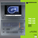
TNC 426
TNC 430
NC Software
280 474-xx
280 475-xx
User's Manual
Conversational
Programming
4/2000
Atitel.pm6
1
28.06.2006, 11:34
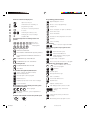
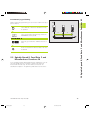
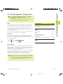
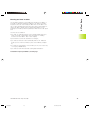
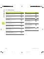
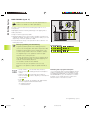
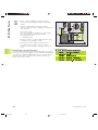
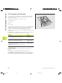
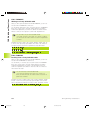
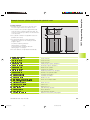
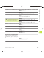
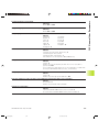
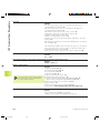
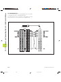
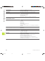
Controls on the visual display unit
APPR
DEP
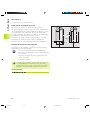
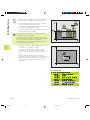
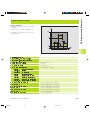
Split screen layout
Controls on the TNC
Programming path movements
Switch between machining or
programming modes
Soft keys for selecting functions
in screen
FK free contour programming
L
Straight line
CC
C
Switching the soft-key rows
Changing the screen settings
(only BC 120)
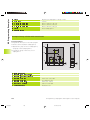
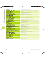
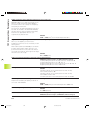
Typewriter keyboard for entering letters and
symbols
Q W E R T Y
File name
Comments
G F S T M
ISO programs
Machine operating modes
MANUAL OPERATION
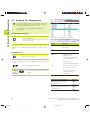
Approach/depart contour
Circle center/pole for polar coordinates
Circle with center
CR
Circle with radius
CT
Circular arc with tangential connection
CHF
RND
Chamfer
Corner rounding
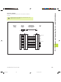
Tool functions
Enter or call tool length and radius
TOOL
TOOL
DEF
CALL
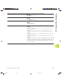
Cycles, subprograms and program section
repeats
CYCL
DEF
CYCL
CALL
LBL
SET
LBL
CALL
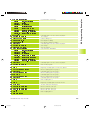
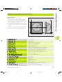
ELECTRONIC HANDWHEEL Operating Modes
POSITIONING WITH MANUAL DATA INPUT
(MDI)
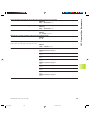
STOP
Program stop in a program
PROGRAM RUN, FULL SEQUENCE
TOUCH
PROBE
Enter touch probe functions in a program
PROGRAMMING AND EDITING
TEST RUN
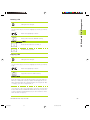
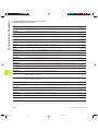
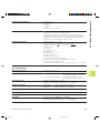
Coordinate axes and numbers, editing
coordinate axes or enter
X ... V Select
them in a program
0 ... 9 Numbers
PGM
CALL
Enter program call in a program
MOD
MOD functions
Decimal point
+/
Program/file management,TNC functions
Select or delete programs and files
PGM
MGT
External data transfer
Change arithmetic sign
P
Polar coordinates
Incremental dimensions
HELP
Displaying help texts for NC error messages
CALC
Pocket calculator
Q
NO
ENT
Move highlight
Go directly to blocks, cycles and parameter
functions
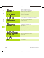
Override control knobs for feed rate/spindle speed
100
END
CE
DEL
50
150
F %
0
Bauskla.pm6
Skip dialog questions, delete words
ENT
100
150
Q parameters
Capture actual position
Moving the cursor, going directly to blocks, cycles
and parameter functions
50
Enter and call labels for
subprogramming and program
section repeats
PROGRAM RUN, SINGLE BLOCK
Programming modes
GOTO
Define and call cycles
Confirm entry and resume
dialog
End block
Clear numerical entry or TNC error
message
Abort dialog, delete program section
S %
0
1
28.06.2006, 11:34
Bauskla.pm6
2
28.06.2006, 11:34
Bauskla.pm6
3
28.06.2006, 11:34
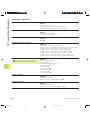
Contents
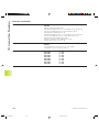
TNC Models, Software and
Features
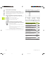
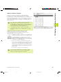
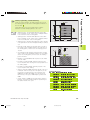
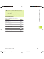
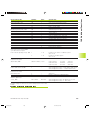
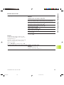
This manual describes functions and features provided by
the TNCs as of the following NC software numbers.
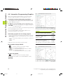
TNC Model
NC Software No.
TNC 426 CB, TNC 426 PB
TNC 426 CF, TNC 426 PF
TNC 426 M
TNC 426 ME
TNC 430 CA, TNC 430 PA
TNC 430 CE, TNC 430 PE
TNC 430 M
TNC 430 ME
280
280
280
280
280
280
280
280
474-xx
475-xx
474-xx
475-xx
474-xx
475-xx
474-xx
475-xx
The suffixes E and F indicate the export versions of the TNC
which have the following limitations:
■ Linear movement is possible in no more than 4 axes
simultaneously
The machine tool builder adapts the useable features of the
TNC to his machine by setting machine parameters. Some
of the functions described in this manual may not be
among the features provided by your machine tool.
TNC functions that may not be available on your machine
include:
■ Probing function for the 3-D touch probe
■ Digitizing option
■ Tool measurement with the TT 120
■ Rigid tapping
■ Returning to the contour after an interruption
Please contact your machine tool builder to become familiar
with the individual implementation of the control on your
machine.
Many machine manufacturers, as well as HEIDENHAIN,
offer programming courses for the TNCs. We recommend
these courses as an effective way of improving your
programming skill and sharing information and ideas with
other TNC users.
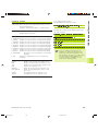
Touch Probe Cycles User's Manual:
All of the touch probe functions are described in
a separate manual. Please contact HEIDENHAIN
if you require a copy of this User's Manual. Id. Nr.:
329 203-xx.
Location of use
The TNC complies with the limits for a Class A device in
accordance with the specifications in EN 55022, and is
intended for use primarily in industrially-zoned areas.
HEIDENHAIN TNC 426, TNC 430
Cinhalt.pm6
1
I
28.06.2006, 11:34
Cinhalt.pm6
2
28.06.2006, 11:34
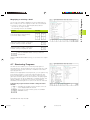
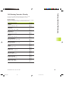
Contents
Contents
1
2
3
4
5
6
7
8
9
10
11
12
13
Introduction
Manual Operation and Setup
Positioning with Manual Data Input (MDI)
Programming: Fundamentals of NC,
File Management, Programming Aids
Programming:Tools
Programming: Programming Contours
Programming: Miscellaneous Functions
Programming: Cycles
Programming: Subprograms and Program
Section Repeats
Programming: Q Parameters
Test Run and Program Run
MOD Functions
Tables and Overviews
HEIDENHAIN TNC 426, TNC 430
Cinhalt.pm6
3
III
28.06.2006, 11:34
Contents
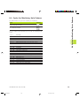
1 INTRODUCTION ..... 1
1.1 The TNC 426, theTNC 430 ..... 2
1.2 Visual Display Unit and Keyboard ..... 3
1.3 Modes of Operation ..... 5
1.4 Status Displays ..... 7
1.5 Accessories: HEIDENHAIN 3-DTouch Probes and Electronic Handwheels ..... 12
2 MANUAL OPERATION AND SETUP ..... 15
2.1 Switch-on, Switch-off ..... 16
2.2 Moving the Machine Axes ..... 17
2.3 Spindle Speed S, Feed Rate F and Miscellaneous Functions M ..... 19
2.4 Datum Setting (Without a 3-DTouch Probe) ..... 20
2.5 Tilting the Working Plane ..... 21
3 POSITIONING WITH MANUAL DATA INPUT (MDI) ..... 25
3.1 Programming and Executing Simple Machining Operations ..... 26
4 PROGRAMMING: FUNDAMENTALS OF NC, FILE MANAGEMENT,
PROGRAMMING AIDS, PALLET MANAGEMENT ..... 29
4.1 Fundamentals of NC ..... 30
4.2 File Management: Fundamentals ..... 35
4.3 Standard File Management ..... 36
4.4 File Management with Additional Functions ..... 42
4.5 Creating and Writing Programs ..... 55
Editing a program ..... 58
4.6 Interactive Programming Graphics ..... 60
4.7 Structuring Programs ..... 61
4.8 Adding Comments ..... 62
4.9 Creating Text Files ..... 63
4.10 Integrated Pocket Calculator ..... 66
4.11 HELP for NC error messages ..... 67
4.12 Managing PalletTables ..... 68
IV
Cinhalt.pm6
Contents
4
28.06.2006, 11:34
Contents
5 PROGRAMMING: TOOLS ..... 71
5.1 EnteringTool-Related Data ..... 72
5.2 Tool Data ..... 73
5.3 Tool Compensation ..... 84
5.4 Three-DimensionalTool Compensation ..... 88
5.5 Working with Cutting DataTables ..... 94
6 PROGRAMMING: PROGRAMMING CONTOURS ..... 101
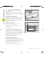
6.1 Overview ofTool Movements ..... 102
6.2 Fundamentals of Path Functions ..... 103
6.3 Contour Approach and Departure ..... 106
Overview:Types of paths for contour approach and departure ..... 106
Important positions for approach and departure ..... 106
Approaching on a straight line with tangential connection: APPR LT ..... 107
Approaching on a straight line perpendicular to the first contour point: APPR LN ..... 108
Approaching on a circular arc with tangential connection: APPR CT ..... 108
Approaching on a circular arc with tangential connection from a straight line to the contour:
APPR LCT ..... 109
Departing tangentially on a straight line: DEP LT ..... 110
Departing on a straight line perpendicular to the last contour point: DEP LN ..... 110
Departing tangentially on a circular arc: DEP CT ..... 111
Departing on a circular arc tangentially connecting the contour and a straight line: DEP LCT ..... 111
6.4 Path Contours — Cartesian Coordinates ..... 112
Overview of path functions ..... 112
Straight line L ..... 113
Inserting a chamfer CHF between two straight lines ..... 113
Circle center CC ..... 114
Circular path C around circle center CC ..... 115
Circular path CR with defined radius ..... 116
Circular path CT with tangential connection ..... 117
Corner Rounding RND ..... 118
Example: Linear movements and chamfers with Cartesian coordinates ..... 119
Example: Circular movements with Cartesian coordinates ..... 120
Example: Full circle with Cartesian coordinates ..... 121
HEIDENHAIN TNC 426, TNC 430
Cinhalt.pm6
5
V
28.06.2006, 11:34
Contents
6.5 Path Contours—Polar Coordinates ..... 122
Polar coordinate origin: Pole CC ..... 122
Straight line LP ..... 123
Circular path CP around pole CC ..... 123
Circular path CTP with tangential connection ..... 124
Helical interpolation ..... 124
Example: Linear movement with polar coordinates ..... 127
Example: Helix ..... 127
6.6 Path Contours — FK Free Contour Programming ..... 128
Fundamentals ..... 128
Graphics during FK programming ..... 128
Initiating the FK dialog ..... 129
Free programming of straight lines ..... 130
Free programming of circular arcs ..... 130
Auxiliary points ..... 132
Relative data ..... 133
Closed contours ..... 135
Converting FK programs ..... 135
Example: FK programming 1 ..... 136
Example: FK programming 2 ..... 137
Example: FK programming 3 ..... 138
6.7 Path Contours - Spline Interpolation ..... 140
VI
Cinhalt.pm6
Contents
6
28.06.2006, 11:34
Contents
7 PROGRAMMING: MISCELLANEOUS FUNCTIONS ..... 143
7.1 Entering Miscellaneous Functions M and STOP ..... 144
7.2 Miscellaneous Functions for Program Run Control, Spindle and Coolant ..... 145
7.3 Miscellaneous Functions for Coordinate Data ..... 145
7.4 Miscellaneous Functions for Contouring Behavior ..... 148
Smoothing corners: M90 ..... 148
Insert rounding arc between straight lines: M112 ..... 149
Machining small contour steps: M97 ..... 149
Machining open contours: M98 ..... 150
Feed rate factor for plunging movements: M103 ..... 151
Feed rate in microns per spindle revolution: M136 ..... 151
Feed rate at circular arcs: M109/M110/M111 ..... 152
Calculating the radius-compensated path in advance (LOOK AHEAD): M120 ..... 152
Superimposing handwheel positioning during program run: M118 ..... 153
7.5 Miscellaneous Functions for Rotary Axes ..... 154
Feed rate in mm/min on rotary axes A, B, C: M116 ..... 154
Shorter-path traverse of rotary axes: M126 ..... 154
Reducing display of a rotary axis to a value less than 360°: M94 ..... 155
Automatic compensation of machine geometry when working with tilted axes: M114 ..... 156
Maintaining the position of the tool tip when positioning with tilted axes (TCPM*): M128 ..... 157
Exact stop at corners with nontangential transitions: M134 ..... 159
Selecting tilting axes: M138 ..... 159
7.6 Miscellaneous Functions for Laser Cutting Machines ..... 160
HEIDENHAIN TNC 426, TNC 430
Cinhalt.pm6
7
VII
28.06.2006, 11:34
Contents
8 PROGRAMMING: CYCLES ..... 161
8.1 General Information on Cycles ..... 162
8.2 Drilling Cycles ..... 164
PECKING (Cycle 1) ..... 164
DRILLING (Cycle 200) ..... 166
REAMING (Cycle 201) ..... 167
BORING (Cycle 202) ..... 168
UNIVERSAL DRILLING (Cycle 203) ..... 169
BACK BORING (Cycle 204) ..... 171
UNIVERSAL PECKING (Cycle 205) ..... 173
BORE MILLING (Cycle 208) ..... 175
TAPPING with a floating tap holder (Cycle 2) ..... 177
TAPPING NEW with floating tap holder (Cycle 206) ..... 178
RIGIDTAPPING (Cycle 17) ..... 180
RIGIDTAPPING without a floating tap holderTAPPING (Cycle 207) ..... 181
THREAD CUTTING (Cycle 18) ..... 183
Example: Drilling cycles ..... 184
Example: Drilling cycles ..... 185
8.3 Cycles for milling pockets, studs and slots ..... 186
POCKET MILLING (Cycle 4) ..... 187
POCKET FINISHING (Cycle 212) ..... 188
STUD FINISHING (Cycle 213) ..... 190
CIRCULAR POCKET MILLING (Cycle 5) ..... 191
CIRCULAR POCKET FINISHING (Cycle 214) ..... 193
CIRCULAR STUD FINISHING (Cycle 215) ..... 194
SLOT MILLING (Cycle 3) ..... 196
SLOT with reciprocating plunge-cut (Cycle 210) ..... 197
CIRCULAR SLOT with reciprocating plunge-cut (Cycle 211) ..... 199
Example: Milling pockets, studs and slots ..... 201
8.4 Cycles for Machining Hole Patterns ..... 203
CIRCULAR PATTERN (Cycle 220) ..... 204
LINEAR PATTERN (Cycle 221) ..... 205
Example: Circular hole patterns ..... 207
VIII
Cinhalt.pm6
Contents
8
28.06.2006, 11:34
Contents
8.5 SL Cycles ..... 209
CONTOUR GEOMETRY (Cycle 14) ..... 211
Overlapping contours ..... 211
CONTOUR DATA (Cycle 20) ..... 213
PILOT DRILLING (Cycle 21) ..... 215
ROUGH-OUT (Cycle 22) ..... 216
FLOOR FINISHING (Cycle 23) ..... 217
SIDE FINISHING (Cycle 24) ..... 217
CONTOURTRAIN (Cycle 25) ..... 218
CYLINDER SURFACE (Cycle 27) ..... 220
CYLINDER SURFACE slot milling (Cycle 28) ..... 222
Example: Roughing-out and fine-roughing a pocket ..... 224
Example: Pilot drilling, roughing-out and finishing overlapping contours ..... 226
Example: Contour train ..... 228
Example: Cylinder surface ..... 230
8.6 Cycles for Multipass Milling ..... 232
RUN DIGITIZED DATA (Cycle 30) ..... 232
MULTIPASS MILLING (Cycle 230) ..... 234
RULED SURFACE (Cycle 231) ..... 236
Example: Multipass milling ..... 238
8.7 CoordinateTransformation Cycles ..... 239
DATUM SHIFT (Cycle 7) ..... 240
DATUM SHIFT with datum tables (Cycle 7) ..... 241
MIRROR IMAGE (Cycle 8) ..... 244
ROTATION (Cycle 10) ..... 245
SCALING FACTOR (Cycle 11) ..... 246
AXIS-SPECIFIC SCALING (Cycle 26) ..... 247
WORKING PLANE (Cycle 19) ..... 248
Example: Coordinate transformation cycles ..... 253
8.8 Special Cycles ..... 255
DWELLTIME (Cycle 9) ..... 255
PROGRAM CALL (Cycle 12) ..... 255
ORIENTED SPINDLE STOP (Cycle 13) ..... 256
TOLERANCE (Cycle 32) ..... 257
HEIDENHAIN TNC 426, TNC 430
Cinhalt.pm6
9
IX
28.06.2006, 11:34
Contents
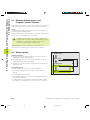
9 PROGRAMMING: SUBPROGRAMS AND PROGRAM SECTION REPEATS ..... 259
9.1 Marking Subprograms and Program Section Repeats ..... 260
9.2 Subprograms ..... 260
9.3 Program Section Repeats ..... 261
9.4 Program as Subprogram ..... 262
9.5 Nesting ..... 263
Subprogram within a subprogram ..... 263
Repeating program section repeats ..... 264
Repeating a subprogram ..... 265
9.6 Programming Examples ..... 266
Example: Milling a contour in several infeeds ..... 266
Example: Groups of holes ..... 267
Example: Groups of holes with several tools ..... 268
10 PROGRAMMING: Q PARAMETERS ..... 271
10.1 Principle and Overview ..... 272
10.2 Part Families — Q Parameters in Place of Numerical Values ..... 274
10.3 Describing ContoursThrough Mathematical Functions ..... 275
10.4Trigonometric Functions ..... 277
10.5 Calculating Circles ..... 278
10.6 If-Then Decisions with Q Parameters ..... 279
10.7 Checking and Changing Q Parameters ..... 280
10.8 Additional Functions ..... 281
10.9 Entering Formulas Directly ..... 293
10.10 Preassigned Q Parameters ..... 296
10.11 Programming Examples ..... 299
Example: Ellipse ..... 299
Example: Concave cylinder machined with spherical cutter ..... 301
Example: Convex sphere machined with end mill ..... 303
11 TEST RUN AND PROGRAM RUN ..... 305
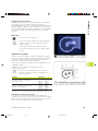
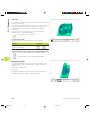
11.1 Graphics ..... 306
11.2 Functions for Program Display in Program Run andTest Run ..... 311
11.3 Test run ..... 311
11.4 Program Run ..... 313
11.5 Optional block skip ..... 318
X
Cinhalt.pm6
Contents
10
28.06.2006, 11:34
Contents
12 MOD FUNCTIONS ..... 319
12.1 Selecting, Changing and Exiting the MOD Functions ..... 320
12.2 Software Numbers and Option Numbers ..... 321
12.3 Code Number ..... 321
12.4 Setting the Data Interfaces ..... 322
12.5 Ethernet Interface ..... 326
12.6 Configuring PGM MGT ..... 333
12.7 Machine-Specific User Parameters ..... 333
12.8 Showing the Workpiece in the Working Space ..... 333
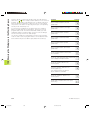
12.9 Position DisplayTypes ..... 335
12.10 Unit of Measurement ..... 335
12.11 Programming Language for $MDI ..... 336
12.12 Selecting the Axes for Generating L Blocks ..... 336
12.13 Axis Traverse Limits, Datum Display ..... 336
12.14 Displaying HELP files ..... 337
12.15 MachiningTimes ..... 338
13 TABLES AND OVERVIEWS ..... 339
13.1 General User Parameters ..... 340
13.2 Pin Layout and Connecting Cable for the Data Interfaces ..... 355
13.3 Technical Information ..... 359
13.4 Exchanging the Buffer Battery ..... 362
HEIDENHAIN TNC 426, TNC 430
Cinhalt.pm6
11
XI
28.06.2006, 11:34
Cinhalt.pm6
12
28.06.2006, 11:34
1
Introduction
Dkap1.pm6
1
28.06.2006, 11:34
1.1 The TNC 426, the TNC 430
1.1 The TNC 426, the TNC 430
HEIDENHAIN TNC controls are workshop-oriented contouring
controls that enable you to program conventional machining
operations right at the machine in an easy-to-use conversational
programming language. They are designed for milling, drilling and
boring machines, as well as for machining centers. The TNC 426 can
control up to 5 axes; the TNC 430 can control up to 9 axes. You can
also change the angular position of the spindle under program
control.
An integrated hard disk provides storage for as many programs as
you like, even if they were created off-line or by digitizing. For quick
calculations you can call up the on-screen pocket calculator at any
time.
Keyboard and screen layout are clearly arranged in a such way that
the functions are fast and easy to use.
Programming: HEIDENHAIN conversational and ISO formats
HEIDENHAIN conversational programming is an especially easy
method of writing programs. Interactive graphics illustrate the
individual machining steps for programming the contour. If a
production drawing is not dimensioned for NC, the HEIDENHAIN
FK free contour programming carries out the necessary calculations
automatically. Workpiece machining can be graphically simulated
either during or before actual machining. It is also possible to
program in ISO format or DNC mode.
You can also enter and test one program while the TNC is running
another.
Compatibility
The TNC can execute all part programs that were written on
HEIDENHAIN controls TNC 150 B and later.
2
Dkap1.pm6
1 Introduction
2
28.06.2006, 11:34
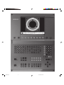
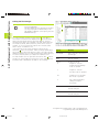
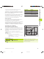
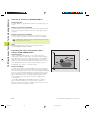
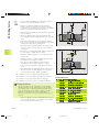
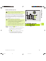
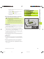
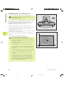
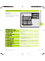
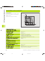
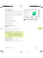
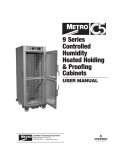
1.2 Visual Display Unit and Keyboard
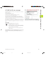
1.2 Visual Display Unit and Keyboard
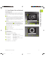
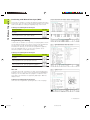
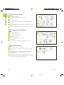
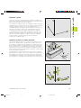
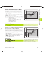
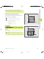
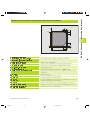
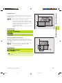
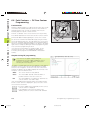
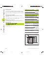
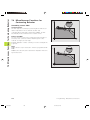
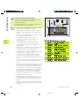
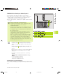
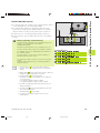
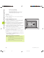
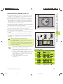
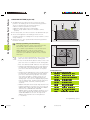
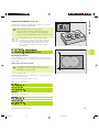
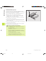
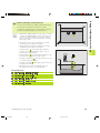
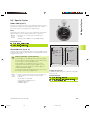
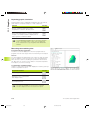
Visual display unit
The TNC is available with either a color CRT screen (BC 120) or a
TFT flat panel display (BF 120. The figures at right show the keys
and controls on the BC 120 (upper right) and the BF 120 (middle
right).
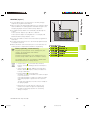
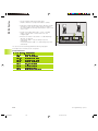
Header
When the TNC is on, the selected operating modes are shown
in the screen header: the machining mode at the left and the
programming mode at right. The currently active mode is
displayed in the larger box, where the dialog prompts and TNC
messages also appear (unless the TNC is showing only
graphics).
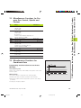
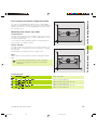
Soft keys
In the footer the TNC indicates additional functions in a soft-key
row. You can select these functions by pressing the keys
immediately below them . The lines immediately above the
soft-key row indicate the number of soft-key rows that can be
called with the black arrow keys to the right and left. The line
representing the active soft-key row is highlighted.
10
Soft key selector keys
Switching the soft-key rows
Setting the screen layout
Shift key for switchover between machining and programming
modes
Keys on BC 120 only
Screen demagnetization;
Exit main menu for screen settings
Select main menu for screen settings;
In the main menu:
Move highlight downward
In the submenu:
Reduce value
Move picture to the left or downward
10
In the main menu:
In the submenu:
Move highlight upward
Increase value
Move picture to the right or upward
In the main menu:
In the submenu:
Select submenu
Exit submenu
See next page for the screen settings.
HEIDENHAIN TNC 426, TNC 430
Dkap1.pm6
3
3
28.06.2006, 11:34
1.2 Visual Display Unit and Keyboard
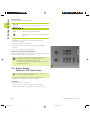
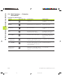
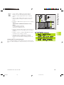
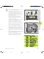
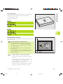
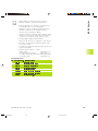
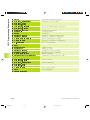
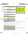
Main menu dialog
Function
BRIGHTNESS
CONTRAST
H-POSITION
H-SIZE
V-POSITION
V-SIZE
SIDE-PIN
TRAPEZOID
ROTATION
COLOR TEMP
R-GAIN
B-GAIN
RECALL
Adjust brightness
Adjust contrast
Adjust horizontal position
Adjust picture width
Adjust vertical position
Adjust picture height
Correct barrel-shaped distortion
Correct trapezoidal distortion
Correct tilting
Adjust color temperature
Adjust strength of red color
Adjust strength of blue color
No function
The BC 120 is sensitive to magnetic and electromagnetic noise,
which can distort the position and geometry of the picture.
Alternating fields can cause the picture to shift periodically or to
become distorted.
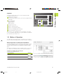
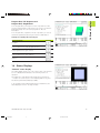
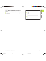
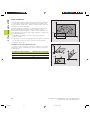
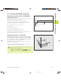
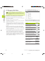
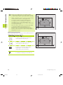
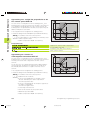
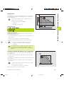
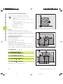
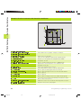
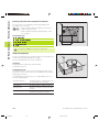
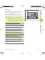
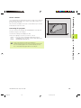
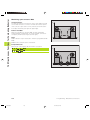
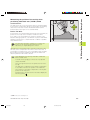
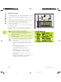
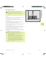
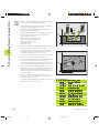
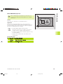
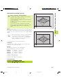
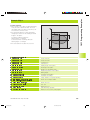
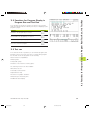
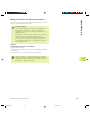
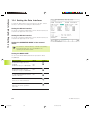
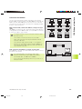
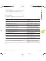
Screen layout
You select the screen layout yourself: In the PROGRAMMING AND
EDITING mode of operation, for example, you can have the TNC
show program blocks in the left window while the right window
displays programming graphics. You could also display the program
structure in the right window instead, or display only program
blocks in one large window. The available screen windows depend
on the selected operating mode.
To change the screen layout:
Press the switch-over key: The soft-key row
shows the available layout options (see section
1.3 ”Modes of Operation”).
<
Select the desired screen layout.
4
Dkap1.pm6
1 Introduction
4
28.06.2006, 11:34
1.3 Modes of Operation
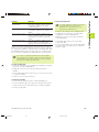
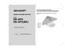
Keyboard
The figure at right shows the keys of the keyboard grouped
according to their functions:
Alphanumeric keyboard
for entering texts and file names, as well as for programming in
ISO format
File management,
pocket calculator,
MOD functions,
HELP functions
Programming modes
Machine operating modes
Initiation of programming dialog
Arrow keys and GOTO jump command
Numerical input and axis selection
The functions of the individual keys are described on the inside
front cover. Machine panel buttons, e.g. NC START, are described in
the manual for your machine tool.
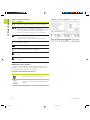
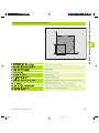
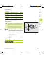
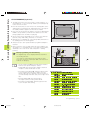
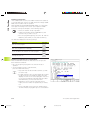
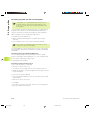
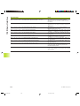
1.3 Modes of Operation
The TNC offers the following modes of operation for the various
functions and working steps that you need to machine a workpiece:
Manual Operation and Electronic Handwheel
The Manual Operation mode is required for setting up the machine
tool. In this operating mode, you can position the machine axes
manually or by increments, set the datums, and tilt the working
plane.
The Electronic Handwheel mode of operation allows you to move
the machine axes manually with the HR electronic handwheel.
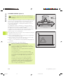
Soft keys for selecting the screen layout
(select as described previously)
Screen windows
Soft key
Positions
Left: positions. Right: status display.
HEIDENHAIN TNC 426, TNC 430
Dkap1.pm6
5
5
28.06.2006, 11:34
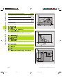
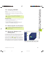
1.3 Modes of Operation
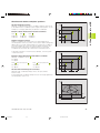
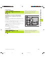
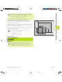
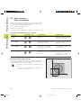
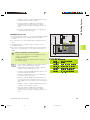
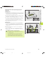
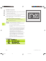
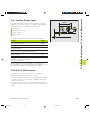
Positioning with Manual Data Input (MDI)
This mode of operation is used for programming simple traversing
movements, such as for face milling or pre-positioning. You can also
define point tables for setting the digitizing range in this mode.
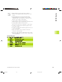
Soft keys for selecting the screen layout
Screen windows
Soft key
Program
Left: program blocks, right: status display
Programming and Editing
In this mode of operation you can write your part programs. The FK
free programming feature, the various cycles and the Q parameter
functions help you with programming and add necessary
information. If desired, you can have the programming graphics
show the individual steps, or you can use a separate screen
window to prepare your program structure.
Soft keys for selecting the screen layout
Screen windows
Soft key
Program
Left: program blocks, right: program structure
Left: program blocks, right: programming graphics
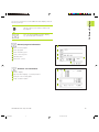
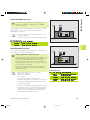
Test run
In the Test Run mode of operation, the TNC checks programs and
program sections for errors, such as geometrical incompatibilities,
missing or incorrect data within the program or violations of the
work space. This simulation is supported graphically in different
display modes.
Soft keys for selecting the screen layout
Same as in the Program Run operating modes on the next page.
6
Dkap1.pm6
1 Introduction
6
28.06.2006, 11:34
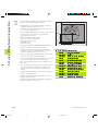
1.4 Status Displays
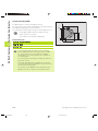
Program Run, Full Sequence and
Program Run, Single Block
In the Program Run, Full Sequence mode of operation the TNC
executes a part program continuously to its end or to a manual or
programmed stop. You can resume program run after an
interruption.
In the Program Run, Single Block mode of operation you execute
each block separately by pressing the machine START button.
Soft keys for selecting the screen layout
Screen windows
Soft key
Program
Left: program blocks, right: program structure
Left: program blocks, right: STATUS
Left: program blocks, right: graphics
Graphics
1.4 Status Displays
“General” status display
The status display informs you of the current state of the machine
tool. It is displayed automatically in the following modes of
operation:
■ Program Run, Single Block and Program Run, Full Sequence,
except if the screen layout is set to display graphics only, and
■ Positioning with Manual Data Input (MDI).
In the operating modes Manual and Electronic Handwheel, the
status display is shown in the large window.
HEIDENHAIN TNC 426, TNC 430
Dkap1.pm6
7
7
28.06.2006, 11:34
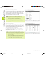
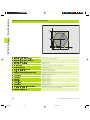
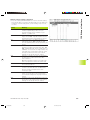
1.4 Status Displays
Information in the status display
The
Meaning
ACTL.
Actual or nominal coordinates of the current position
XY Z
Machine axes; the TNC displays auxiliary axes in
lower-case letters. The sequence and quantity of displayed
axes is determined by the machine tool builder.
Refer to your machine manual for more information
F S M
The displayed feed rate in inches corresponds to
one tenth of the effective value.
Spindle speed S, feed rate F and active M functions
Program run started
Axis locked
Axis can be moved with the handwheel
Axes are moving in a tilted working
plain
Axes are moving under a basic
rotation
Additional status displays
The additional status displays contain detailed information on the
program run. They can be called in all operating modes, except in
the Programming and Editing mode of operation.
To switch on the additional status display:
Call the soft-key row for screen layout.
<
Select the layout option for the additional status
display.
8
Dkap1.pm6
1 Introduction
8
28.06.2006, 11:34
1.4 Status Displays
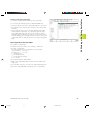
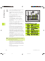
You can choose between several additional status displays with the
following soft keys:
Shift the soft-key rows until the STATUS soft
keys appear.
<
Select the desired additional status display,
e.g. general program information.
General program information
Name of main program
Active programs
Active machining cycle
Circle center CC (pole)
Operating time
Dwell time counter
Positions and coordinates
Position display
Type of position display, e.g. actual positions
Tilt angle of the working plane
Angle of a basic rotation
HEIDENHAIN TNC 426, TNC 430
Dkap1.pm6
9
9
28.06.2006, 11:34
1.4 Status Displays
Information on tools
T: Tool number and name
RT: Number and name of a replacement tool
Tool axis
Tool length and radii
Oversizes (delta values) from TOOL CALL (PGM) and the tool
table (TAB)
Tool life, maximum tool life (TIME 1) and maximum tool life for
TOOL CALL (TIME 2)
Display of the active tool and the (next) replacement tool
Coordinate transformations
Name of main program
Active datum shift (Cycle 7)
Active rotation angle (Cycle 10)
Mirrored axes (Cycle 8)
Active scaling factor(s) (Cycles 11 / 26)
Scaling datum
See also section 8.7 “Coordinate Transformation Cycles.”
Tool measurement
Number of the tool to be measured
Display whether the tool radius or the tool length is being
measured
MIN and MAX values of the individual cutting edges and the
result of measuring the rotating tool (DYN = dynamic
measurement)
Cutting edge number with the corresponding measured value.
If the measured value is followed by an asterisk, the allowable
tolerance in the tool table was exceeded.
10
Dkap1.pm6
1 Introduction
10
28.06.2006, 11:34
1.4 Status Displays
Active miscellaneous functions M
List of the active M functions with fixed meaning.
List of the active M functions with function assigned by machine
manufacturer.
HEIDENHAIN TNC 426, TNC 430
Dkap1.pm6
11
11
28.06.2006, 11:34
1.5 Accessories: HEIDENHAIN 3-D Touch Probes and Electronic Handwheels
1.5 Accessories: HEIDENHAIN 3-D
Touch Probes and Electronic
Handwheels
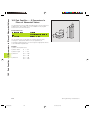
3-D Touch Probes
With the various HEIDENHAIN 3-D touch probe systems you can:
■ Automatically align workpieces
■ Quickly and precisely set datums
■ Measure the workpiece during program run
■ Digitize 3-D surfaces (option), and
■ Measure and inspect tools
All of the touch probe functions are described in a
separate manual. Please contact HEIDENHAIN if you
require a copy of this User's Manual. Id. Nr.: 329 203 xx.
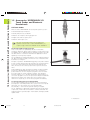
TS 220 and TS 630 touch trigger probes
These touch probes are particularly effective for automatic
workpiece alignment, datum setting, workpiece measurement and
for digitizing. The TS 220 transmits the triggering signals to the TNC
via cable and is a cost-effective alternative for applications where
digitizing is not frequently required.
The TS 630 features infrared transmission of the triggering signal to
the TNC. This makes it highly convenient for use on machines with
automatic tool changers.
Principle of operation: HEIDENHAIN triggering touch probes feature
a wear resisting optical switch that generates an electrical signal as
soon as the stylus is deflected. This signal is transmitted to the
TNC, which stores the current position of the stylus as an actual
value.
During digitizing the TNC generates a program containing straight
line blocks in HEIDENHAIN format from a series of measured
position data. You can then output the program to a PC for further
processing with the SUSA evaluation software. This evaluation
software enables you to calculate male/female transformations or
correct the program to account for special tool shapes and radii that
differ from the shape of the stylus tip. If the tool has the same
radius as the stylus tip you can run these programs immediately.
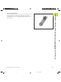
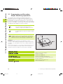
TT 120 tool touch probe for tool measurement
The TT 120 is a triggering 3-D touch probe for tool measurement
and inspection. Your TNC provides three cycles for this touch probe
with which you can measure the tool length and radius
automatically — either with the spindle rotating or stopped.
The TT 120 features a particularly rugged design and a high degree
of protection, which make it insensitive to coolants and swarf. The
triggering signal is generated by a wear-resistant and highly reliable
optical switch.
12
Dkap1.pm6
1 Introduction
12
28.06.2006, 11:34
1.5 Accessories: HEIDENHAIN 3-D Touch Probes and Electronic Handwheels
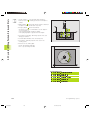
HR electronic handwheels
Electronic handwheels facilitate moving the axis slides precisely by
hand. A wide range of traverses per handwheel revolution is
available. Apart from the HR 130 and HR 150 integral handwheels,
HEIDENHAIN also offers the HR 410 portable handwheel (see
figure at right).
HEIDENHAIN TNC 426, TNC 430
Dkap1.pm6
13
13
28.06.2006, 11:34
Dkap1.pm6
14
28.06.2006, 11:34
2
Manual Operation and Setup
Dkap2_3.pm6
15
28.06.2006, 11:34
2.1 Switch-on, Switch-off
2.1 Switch-on, Switch-off
Switch-On
Switch-on and traversing the reference points can vary
depending on the individual machine tool. Your machine
manual provides more detailed information.
Switch on the power supply for control and machine.
The TNC automatically initiates the following dialog
Memory Test
<
The TNC memory is automatically checked.
Power Interrupted
<
TNC message that the power was interrupted
— clear the message.
Translate PLC Program
<
The PLC program of the TNC is automatically compiled.
Relay Ext. DC Voltage Missing
<
Switch on the control voltage.
The TNC checks the functioning of the
EMERGENCY STOP circuit.
Manual Operation
Traverse Reference Points
<
Cross the reference points manually in the
displayed sequence: For each axis press the
machine START button, or
cross the reference points in any sequence:
Press and hold the machine axis direction
button for each axis until the reference point has
been traversed.
The reference points need only be
traversed if the machine axes are to be
moved. If you intend only to write, edit or
test programs, you can select the
Programming and Editing or Test Run
modes of operation immediately after
switching on the control voltage.
You can then traverse the reference
points later by pressing the PASS OVER
REFERENCE soft key in the Manual
Operation mode.
Traversing the reference point in a tilted working
plane
The reference point of a tilted coordinate system
can be traversed by pressing the machine axis
direction buttons. The “tilting the working plane”
function (see section 2.5 “Tilting the Working
Plane”) must be active in the Manual Operation
mode. The TNC then interpolates the corresponding
axes.
The NC START button is not effective. Pressing this
button may result in an error message.
Make sure that the angle values entered in the
menu for tilting the working plane match the actual
angle of the tilted axis.
Switch-off
To prevent data being lost at switch-off, you need to
run down the operating system as follows:
ú Select the Manual mode
ú Select the function for run-down,
confirm again with the YES soft key.
ú When the TNC displays the message
„Now you can switch off the TNC“ in a
superimposed window, you may cut
off the power supply to the TNC.
Inappropriate switch-off of the TNC can
lead to data loss.
The TNC is now ready for operation in the
Manual Operation mode.
16
Dkap2_3.pm6
2 Manual Operation and Setup
16
28.06.2006, 11:34
2.2 Moving the Machine Axes
2.2 Moving the Machine Axes
Traversing with the machine axis direction buttons is a
machine-dependent function. Refer to your machine tool
manual for more information.
To traverse with the machine axis direction buttons:
Select the Manual Operation mode.
<
Press the machine axis direction button and
hold it as long as you wish the axis to move.
...or move the axis continuously:
and
Press and hold the machine axis direction
button, then press the machine START button:
The axis continues to move after you release
the keys.
To stop the axis, press the machine STOP
button.
You can move several axes at a time with these two methods. You
can change the feed rate at which the axes are traversed with the F
soft key (see „2.3 Spindle Speed S, Feed Rate F and Miscellaneous
Functions M).
HEIDENHAIN TNC 426, TNC 430
Dkap2_3.pm6
17
17
28.06.2006, 11:34
2.2 Moving the Machine Axes
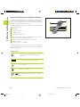
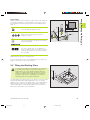
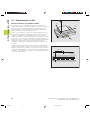
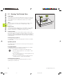
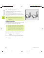
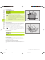
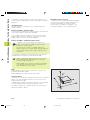
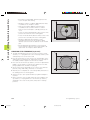
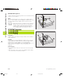
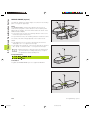
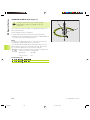
Traversing with the HR 410 electronic handwheel
The portable HR 410 handwheel is equipped with two permissive
buttons. The permissive buttons are located below the star grip.
You can only move the machine axes when an permissive button is
depressed (machine-dependent function).
The HR 410 handwheel features the following operating elements:
EMERGENCY STOP
Handwheel
Permissive buttons
Axis address keys
Actual-position-capture key
Keys for defining the feed rate (slow, medium, fast; the feed
rates are set by the machine tool builder)
Direction in which the TNC moves the selected axis
Machine function
(set by the machine tool builder)
The red indicators show the axis and feed rate you have selected.
It is also possible to move the machine axes with the handwheel
during a program run.
To move an axis:
Select the Electronic Handwheel mode of
operation
Press and hold the permissive button.
<
Select the axis.
<
Select the feed rate.
<
or
Move the active axis in the positive or negative
direction.
18
Dkap2_3.pm6
2 Manual Operation and Setup
18
28.06.2006, 11:34
2.3 Spindle Speed S, Feed Rate F and Miscellaneous Functions M
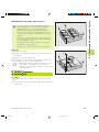
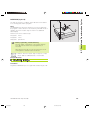
Incremental jog positioning
With incremental jog positioning you can move a machine axis by a
preset distance.
Z
Select Manual or Electronic Handwheel mode
of operation
<
8
8
Select incremental jog positioning: Switch the
INCREMENT soft key to ON
Jog increment =
<
8
16
X
Enter the jog increment in millimeters (here, 8
mm).
<
Press the machine axis direction button as often
as desired.
2.3 Spindle Speed S, Feed Rate F and
Miscellaneous Functions M
In the operating modes Manual and Electronic Handwheel, you can
enter the spindle speed S, feed rate F and the miscellaneous
functions M with soft keys. The miscellaneous functions are
described in Chapter 7 ”Programming: Miscellaneous Functions.”
HEIDENHAIN TNC 426, TNC 430
Dkap2_3.pm6
19
19
28.06.2006, 11:34
2.4 Setting the Datum
Entering values
Example: Entering the spindle speed S
To enter the spindle speed, press the S soft key.
Spindle speed S=
<
1000
Enter the desired spindle speed,
and confirm your entry with the machine START
button.
The spindle speed S with the entered rpm is started with a
miscellaneous function.
The following is valid for feed rate F:
■ If you enter F=0, then the lowest feed rate from MP1020 is
effective
■ F is not lost during a power interruption
Changing the spindle speed and feed rate
With the override knobs you can vary the spindle speed S and feed
rate F from 0% to 150% of the set value.
The knob for spindle speed override is effective only on
machines with an infinitely variable spindle drive.
The machine tool builder determines which
miscellaneous functions M are available on your TNC and
what effects they have.
2.4 Datum Setting
(Without a 3-D Touch Probe)
For datum setting with a 3-D touch probe, refer to the
new Touch Probe Cycles Manual
You fix a datum by setting the TNC position display to the
coordinates of a known position on the workpiece.
Preparation
ú Clamp and align the workpiece.
ú Insert the zero tool with known radius into the spindle.
ú Ensure that the TNC is showing the actual position values.
2 Manual Operation and Setup
20
Dkap2_3.pm6
20
28.06.2006, 11:34
Y
Z
X
Select the Manual Operation mode.
Y
<
X
Move the tool slowly until it touches the
workpiece surface.
<
Select an axis (all axes can also be selected via
the ASCII keyboard)
Datum Set Z=
<
Zero tool in spindle axis: Set the display to a
known workpiece position (here, 0) or enter the
thickness d of the shim. In the tool axis, offset
the tool radius.
Repeat the process for the remaining axes.
If you are using a preset tool, set the display of the tool axis to the
length L of the tool or enter the sum Z=L+d.
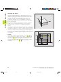
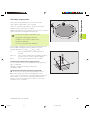
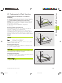
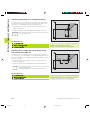
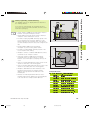
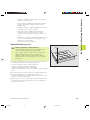
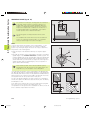
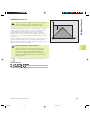
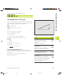
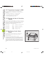
2.5 Tilting the Working Plane
The functions for tilting the working plane are interfaced
to the TNC and the machine tool by the machine tool
builder. With some swivel heads and tilting tables, the
machine tool builder determines whether the entered
angles are interpreted as coordinates of the tilt axes or
as angular components of a tilted plane. Your machine
manual provides more detailed information.
Y
Z
B
10°
The TNC supports the tilting functions on machine tools with swivel
heads and/or tilting tables. Typical applications are, for example,
oblique holes or contours in an oblique plane. The working plane is
always tilted around the active datum. The program is written as
usual in a main plane, such as the X/Y plane, but is executed in a
plane that is tilted relative to the main plane.
X
HEIDENHAIN TNC 426, TNC 430
Dkap2_3.pm6
21
21
28.06.2006, 11:34
2.5 Tilting the Working Plane
Datum setting
Fragile workpiece? If the workpiece surface must not be scratched,
you can lay a metal shim of know thickness d on it. Then enter a
tool axis datum value that is larger than the desired datum by the
value d.
2.5 Tilting the Working Plane
There are two functions available for tilting the working plane
■ 3-D ROT soft key in the Manual mode and Electronic Handwheel
mode (described below)
■ Tilting under program control: Cycle 19 WORKING PLANE in the
part program: see „8.7 Coordinate Transformation Cycles“.
The TNC functions for “tilting the working plane” are coordinate
transformations in which the working plane is always perpendicular
to the direction of the tool axis.
When tilting the working plane, the TNC differentiates between
two machine types
Machines with tilting tables:
■ You must tilt the workpiece into the desired position for
machining by positioning the tilting table, for example with an L
block.
■ The position of the transformed tool axis does not change in
relation to the machine-based coordinate system. Thus if you
rotate the table — and therefore the workpiece — by 90° for
example, the coordinate system does not rotate. If you press the
Z+ axis direction button in the Manual Operation mode, the tool
moves in Z+ direction.
■ In calculating the transformed coordinate system, the TNC
considers only the mechanically influenced offsets of the
particular tilting table (the so-called “translational” components).
Machines with swivel heads
■ You must bring the tool into the desired position for machining by
positioning the swivel head, for example with an L block.
■ The position of the transformed tool axis changes in relation to
the machine-based coordinate system. Thus if you rotate the
swivel head — and therefore the tool — in the B axis by 90° for
example, the coordinate system rotates also. If you press the
Z+ axis direction button in the Manual Operation mode, the tool
moves in X+ direction of the machine-based coordinate system.
■ In calculating the transformed coordinate system, the TNC
considers both the mechanically influenced offsets of the
particular swivel head (the so-called “translational” components)
and offsets caused by tilting of the tool (3-D tool length
compensation).
Traversing the reference points in tilted axes
With tilted axes, you use the machine axis direction buttons to
cross over the reference points. The TNC interpolates the
corresponding axes. Be sure that the function for tilting the working
plane is active in the Manual Operation mode and the actual angle
of the tilted axis was entered in the menu field.
22
Dkap2_3.pm6
2 Manual Operation and Setup
22
28.06.2006, 11:34
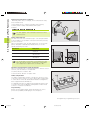
Position display in a tilted system
The positions displayed in the status window
(ACTL. and NOML.) are referenced to the tilted
coordinate system.
Limitations on working with the tilting function
■ The touch probe function Basic Rotation cannot
You must not set the datum in the tilted working plane if
in machine parameter 7500 bit 3 is set. If you do, the
TNC will calculate the wrong offset.
If your machine tool is not equipped with axis control,
you must enter the actual position of the rotary axis in
the menu for manual tilting: The actual positions of one
or several rotary axes must match the entry. Otherwise
the TNC will calculate an incorrect datum.
be used.
■ PLC positioning (determined by the machine tool
builder) is not possible.
■ Positioning blocks with M91/M92 are not
permitted.
Datum setting on machines with rotary tables
The behavior of the TNC during datum setting depends
on the machine.Your machine manual provides more
detailed information.
The TNC automatically shifts the datum if you rotate the table and
the tilted working plane function is active.
MP 7500, bit 3=0
To calculate the datum, the TNC uses the difference between the
REF coordinate during datum setting and the REF coordinate of the
tilting axis after tilting. The method of calculation is to be used
when you have clamped your workpiece in proper alignment when
the rotary table is in the 0° position (REF value).
MP 7500, bit 3=1
If you rotate the table to align a workpiece that has been clamped in
an unaligned position, the TNC must no longer calculate the offset
of the datum from the difference of the REF coordinates. Instead of
the difference from the 0° position, the TNC uses the REF value of
the tilting table after tilting. In other words, it assumes that you
have properly aligned the workpiece before tilting.
HEIDENHAIN TNC 426, TNC 430
Dkap2_3.pm6
23
23
28.06.2006, 11:34
2.5 Tilting the Working Plane
Setting the datum in a tilted coordinate system
After you have positioned the rotary axes, set the datum in the
same way as for a non-tilted system. The TNC then converts the
datum for the tilted coordinate system. If your machine tool
features axis control, the angular values for this calculation are
taken from the actual position of the rotary axis.
2.5 Tilting the Working Plane
To activate manual tilting:
To select manual tilting, press the 3-D ROT soft
key.
You can now select the desired menu option
with the arrow keys.
<
Enter the tilt angle.
<
To set the desired operating mode in menu option ”Tilt working
plane” to Active, select the menu option and shift with the ENT
key.
<
To conclude entry, press the END soft key.
To reset the tilting function, set the desired operating modes in
menu ”Tilt working plane” to Inactive.
If the Working Plane function is active and the TNC moves the
machine axes in accordance with the tilted axes, the status display
.
shows the symbol
If you set the function ”Tilt working plane” for the operating mode
Program Run to Active, the tilt angle entered in the menu becomes
active in the first block of the part program. If you are using Cycle 19
WORKING PLANE in the part program, the angular values defined in
the cycle (starting at the cycle definition) are effective. Angular
values entered in the menu will be overwritten.
24
Dkap2_3.pm6
2 Manual Operation and Setup
24
28.06.2006, 11:34
3
Positioning with Manual Data
Input (MDI)
Dkap2_3.pm6
25
28.06.2006, 11:34
3.1 Programming and Executing Simple Machining Operations
3.1 Programming and Executing
Simple Machining Operations
The operating mode Positioning with Manual Data Input is
particularly convenient for simple machining operations or prepositioning of the tool. It enables you to write a short program in
HEIDENHAIN conversational programming or in ISO format, and
execute it immediately. You can also call TNC cycles. The program is
stored in the file $MDI. In the operating mode Positioning with MDI,
the additional status displays can also be activated.
Select the Positioning with MDI mode of
operation. Program the file $MDI as you wish.
To start program run, press the machine START
button.
Limitation: FK free contour programming, programming
graphics and program run graphics cannot be used. The
$MDI file must not contain a program call (PGM CALL).
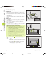
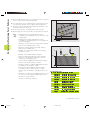
Example 1
A hole with a depth of 20 mm is to be drilled into a single
workpiece. After clamping and aligning the workpiece and setting
the datum, you can program and execute the drilling operation in a
few lines.
Z
Y
X
50
First you pre-position the tool in L blocks (straight-line blocks) to the
hole center coordinates at a setup clearance of 5 mm above the
workpiece surface. Then drill the hole with Cycle 1 PECKING.
0 BEGIN PGM $MDI MM
1 TOOL DEF 1 L+0 R+5
2 TOOL CALL 1 Z S2000
3 L Z+200 R0 F MAX
4 L X+50 Y+50 R0 F MAX M3
5 L Z+5 F2000
6 CYCL DEF 1.0 PECKING
26
Dkap2_3.pm6
50
Define tool: zero tool, radius 5
Call tool: tool axis Z
Spindle speed 2000 rpm
Retract tool (F MAX = rapid traverse)
Move the tool at FMAX to a position above the
borehole, spindle on
Position tool to 5 mm above hole
Define PECKING cycle:
3 Positioning with Manual Data Input (MDI)
26
28.06.2006, 11:34
Setup clearance of the tool above the hole
Total hole depth (Algebraic sign=working direction)
Depth of each infeed before retraction
Dwell time in seconds at the hole bottom
Feed rate for pecking
Call PECKING cycle
Retract tool
End of program
The straight-line function is described in section 6.4 “Path Contours
— Cartesian Coordinates,” the PECKING cycle in section 8.2 “Drilling Cycles.”
Example 2
Correcting workpiece misalignment on machines with rotary tables
Use the 3-D touch probe to rotate the coordinate system. See
the User's Manual for Touch Probe Cycles, chapter ”Touch Probe
Cycles in the Manual and Electronic Handwheel Modes,” section
”Compensating Workpiece Misalignment.”
<
Write down the Rotation Angle and cancel the Basic Rotation.
<
Select operating mode: Positioning with MDI.
<
Select the axis of the rotary table, enter the
rotation angle you wrote down previously and
set the feed rate.
For example: L C+2.561 F50
<
Conclude entry.
<
Press the machine START button: The rotation of
the table corrects the misalignment.
HEIDENHAIN TNC 426, TNC 430
Dkap2_3.pm6
27
27
28.06.2006, 11:34
3.1 Programming and Executing Simple Machining Operations
7 CYCL DEF 1.1 SET UP 5
8 CYCL DEF 1.2 DEPTH -20
9 CYCL DEF 1.3 PECKG 10
10 CYCL DEF 1.4 DWELL 0.5
11 CYCL DEF 1.5 F250
12 CYCL CALL
13 L Z+200 R0 F MAX M2
14 END PGM $MDI MM
3.1 Programming and Executing Simple Machining Operations
Protecting and erasing programs in $MDI
The $MDI file is generally intended for short programs that are only
needed temporarily. Nevertheless, you can store a program, if
necessary, by proceeding as described below:
Select operating mode: Programming
and Editing
<
To call the file manager, press the PGM MGT
key (program management).
<
Move the highlight to the $MDI file.
<
Select „Copy file“: Press the COPY soft key
Target file =
<
BOREHOLE
Enter the name under which you want to save
the current contents of the $MDI file.
<
Copy the file.
<
To close the file manager, press the END soft
key.
Erasing the contents of the $MDI file is done in a similar way:
Instead of copying the contents, however, you erase them with the
DELETE soft key. The next time you select the Positioning with MDI
operating mode, the TNC will display an empty $MDI file.
If you wish to delete $MDI, then
you must not have selected the Positioning with MDI
mode (not even in the background).
you must not have selected the $MDI file in the
Programming and Editing mode.
For further information, refer to section 4.2 “File Management.”
28
Dkap2_3.pm6
3 Positioning with Manual Data Input (MDI)
28
28.06.2006, 11:34
4
Programming:
Fundamentals of NC, File
Management,
Programming Aids, Pallet
Management
Ekap4.pm6
29
28.06.2006, 11:34
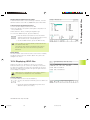
4.1 Fundamentals of NC
4.1 Fundamentals of NC
Z
Position encoders and reference marks
Y
The machine axes are equipped with position encoders that
register the positions of the machine table or tool. When a machine
axis moves, the corresponding position encoder generates an
electrical signal. The TNC evaluates this signal and calculates the
precise actual position of the machine axis.
X
If there is an interruption of power, the calculated position will no
longer correspond to the actual position of the machine slide. The
CNC can re-establish this relationship with the aid of reference
marks when power is returned. The scales of the position encoders
contain one or more reference marks that transmit a signal to the
TNC when they are crossed over. From the signal the TNC identifies
that position as the machine-axis reference point and can reestablish the assignment of displayed positions to machine axis
positions.
Linear encoders are generally used for linear axes. Rotary tables
and tilt axes have angle encoders. If the position encoders feature
distance-coded reference marks, you only need to move each axis a
maximum of 20 mm (0.8 in.) for linear encoders, and 20° for angle
encoders, to re-establish the assignment of the displayed positions
to machine axis positions.
XMP
X (Z,Y)
30
Ekap4.pm6
4 Programming: Fundamentals of NC, File Management,
Programming Aids, Pallet Management
30
28.06.2006, 11:34
4.1 Fundamentals of NC
Reference system
A reference system is required to define positions in a plane or in
space. The position data are always referenced to a predetermined
point and are described through coordinates.
The Cartesian coordinate system (a rectangular coordinate system)
is based on three coordinate axes X, Y and Z. The axes are mutually
perpendicular and intersect at one point called the datum. A
coordinate identifies the distance from the datum in one of these
directions. A position in a plane is thus described through two
coordinates, and a position in space through three coordinates.
Z
Y
X
Coordinates that are referenced to the datum are referred to as
absolute coordinates. Relative coordinates are referenced to any
other known position (datum) you define within the coordinate
system. Relative coordinate values are also referred to as
incremental coordinate values.
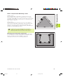
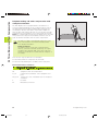
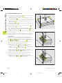
Reference systems on milling machines
When using a milling machine, you orient tool movements to the
Cartesian coordinate system. The illustration at right shows how
the Cartesian coordinate system describes the machine axes. The
figure at right illustrates the “right-hand rule” for remembering the
three axis directions: the middle finger is pointing in the positive
direction of the tool axis from the workpiece toward the tool (the Z
axis), the thumb is pointing in the positive X direction, and the index
finger in the positive Y direction.
+Z
+Y
The TNC 426 can control a machine tool in up to 5 axes; the TNC
430 controls up to 9 axes. The axes U, V and W are secondary linear
axes parallel to the main axes X, Y and Z, respectively. Rotary axes
are designated as A, B and C. The illustration at lower right shows
the assignment of secondary axes and rotary axes to the main axes.
+X
+Z
+X
+Y
Z
Y
W+
C+
B+
V+
X
A+
U+
HEIDENHAIN TNC 426, TNC 430
Ekap4.pm6
31
31
28.06.2006, 11:34
4.1 Fundamentals of NC
Polar coordinates
If the production drawing is dimensioned in Cartesian coordinates,
you also write the part program using Cartesian coordinates. For
parts containing circular arcs or angles it is often simpler to give the
dimensions in polar coordinates.
While the Cartesian coordinates X, Y and Z are three-dimensional
and can describe points in space, polar coordinates are twodimensional and describe points in a plane. Polar coordinates have
their datum at a circle center (CC), or pole. A position in a plane can
be clearly defined by the
Y
PR
PA2
PA3
PR
PR
PA1
10
0°
CC
■ Polar Radius, the distance from the circle center CC to the
position, and the
X
30
■ Polar Angle, the size of the angle between the reference axis and
the line that connects the circle center CC with the position.
See figure at lower right.
Definition of pole and angle reference axis
The pole is set by entering two Cartesian coordinates in one of the
three planes. These coordinates also set the reference axis for the
polar angle PA.
Coordinates of the pole (plane)
Reference axis of the angle
XY
YZ
ZX
+X
+Y
+Z
Y
Z
Z
Y
X
Z
Y
X
X
32
Ekap4.pm6
4 Programming: Fundamentals of NC, File Management,
Programming Aids, Pallet Management
32
28.06.2006, 11:34
4.1 Fundamentals of NC
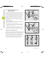
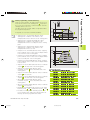
Absolute and relative workpiece positions
Absolute workpiece positions
Absolute coordinates are position coordinates that are referenced
to the datum of the coordinate system (origin). Each position on the
workpiece is uniquely defined by its absolute coordinates.
Y
30
Example 1: Holes dimensioned in absolute coordinates
Hole
Hole
Hole
20
X=10 mm
Y=10 mm
10
X=30 mm
Y=20 mm
X=50 mm
Y=30 mm
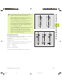
Relative workpiece positions
Relative coordinates are referenced to the last programmed
nominal position of the tool, which serves as the relative (imaginary)
datum. When you write a part program in incremental coordinates,
you thus program the tool to move by the distance between the
previous and the subsequent nominal positions. Incremental
coordinates are therefore also referred to as chain dimensions.
X
10
To program a position in incremental coordinates, enter the prefix
“I” before the axis.
50
30
Y
Example 2: Holes dimensioned with relative coordinates
Absolute coordinates of hole :
referenced to hole
IX= 20 mm
IY= 10 mm
Hole
referenced to hole
10
Hole
10
X= 10 mm
Y= 10 mm
IX= 20 mm
IY= 10 mm
10
Absolute and incremental polar coordinates
Absolute polar coordinates always refer to the pole and the
reference axis.
X
20
20
10
Incremental polar coordinates always refer to the last programmed
nominal position of the tool.
Y
+IPR
PR
PR
+IPA +IPA
PR
PA
10
0°
CC
X
30
HEIDENHAIN TNC 426, TNC 430
Ekap4.pm6
33
33
28.06.2006, 11:34
A production drawing identifies a certain form element of the
workpiece, usually a corner, as the absolute datum. Before setting
the datum, you align the workpiece with the machine axes and
move the tool in each axis to a known position relative to the
workpiece. You then set the TNC display to either zero or a
predetermined position value. This establishes the reference
system for the workpiece, which will be used for the TNC display
and your part program.
Z
Y
X
If the production drawing is dimensioned in relative coordinates,
simply use the coordinate transformation cycles. For further
information, refer to section 8.7 “Coordinate Transformation
Cycles.”
If the production drawing is not dimensioned for NC, set the datum
at a position or corner on the workpiece, which is the most suitable
for deducing the dimensions of the remaining workpiece positions.
The fastest, easiest and most accurate way of setting the datum is
by using a 3-D touch probe from HEIDENHAIN. See the new Touch
Probe Cycles User's Manual, chapter „Setting the Datum with a 3-D
Touch Probe“.
150
0
750
320
-150
0
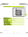
Example
The workpiece drawing at right illustrates the holes to , which
are dimensioned to an absolute datum with the coordinates X=0
Y=0. The holes to are referenced to a relative datum with the
absolute coordinates X=450 Y=750. By using the DATUM SHIFT
cycle you can shift the datum temporarily to the position X=450,
Y=750 and program the holes to without any further
calculations.
Y
300±0,1
4.1 Fundamentals of NC
Selecting the datum
325 450
900
X
950
34
Ekap4.pm6
4 Programming: Fundamentals of NC, File Management,
Programming Aids, Pallet Management
34
28.06.2006, 11:34
Using the MOD function PGM MGT (see Section 12.6),
select between standard file management and file
management with additional functions.
If the TNC is connected to a network (optional), then use
file management with additional functions.
Files
Files in theTNC
Type
When you write a part program on the TNC, you must first enter a
file name. The TNC then stores the program on the hard disk as a
file with this name. You can also store texts and tables as files.
Programs
in HEIDENHAIN conversational format
in ISO format
.H
.I
The TNC provides a special file management window in which you
can easily find and manage your files. Here you can call, copy,
rename and erase files.
You can manage any number of files on the TNC’s hard disk. Their
total size, however, must not exceed 1500 MB.
File names
The name of a file can have up to 16 characters. When you store
programs, tables and texts as files, the TNC adds an extension to
the file name, separated by a point. This extension identifies the file
type (see table at right).
PROG20
.H
File name
File type
Tables for
Tools
Tool changer
Pallets
Datums
Points (digitizing range for
measuring touch probe)
Cutting data
Cutting materials and other materials
Texts as
ASCII files
.T
.TCH
.P
.D
.PNT
.CDT
.TAB
.A
Data security
We recommend saving newly written programs and files on a PC at
regular intervals. You can do this with the cost-free backup program
TNCBACK.EXE from HEIDENHAIN. Your machine tool builder can
provide you with a copy of TNCBACK.EXE.
You also need a floppy disk on which all the machine-specific data
(PLC program, machine parameters, etc.) of your machine tool are
stored. Please contact your machine tool builder for more
information on both the backup program and the floppy disk.
Saving the contents of the entire hard disk (up to 1500
MB) can take up to several hours. In this case, it is a good
idea to save the data outside of working hours, (e.g.
overnight), or to use the PARALLEL EXECUTE function to
copy in the background while you work.
HEIDENHAIN TNC 426, TNC 430
Ekap4.pm6
35
35
28.06.2006, 11:34
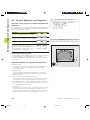
4.2 File Management: Fundamentals
4.2 File Management: Fundamentals
4.3 Standard File Management
4.3 Standard File Management
Use the standard file manager if you want to store all of
the files in one directory, or if you are used to working
with the file manager on old TNC controls.
Set the MOD function PGM MGT to Standard (see
Section 12.6) .
Calling the file manager
Press the PGM MGT:
The TNC displays the file management window
(see Fig. at top right)
The window shows you all of the files that are stored in the TNC.
Each file is shown with additional information, see table at center
right.
Selecting a file.
Calling the file manager
display.
Meaning
FILE NAME
Name with max. 16 characters
and file type
BYTE
File size in bytes
STATUS
E
Property of the file:
Program is in the
Programming and Editing
mode of operation
<
Use the arrow keys to move the highlight to the file you wish to
select:
Move the highlight up or down.
S
Program is in the
Test Run mode of operation.
M
Program is in the Program
Run mode of operation.
P
File is protected against
editing and erasure
(Protected)
<
or
Select a file: Press the SELECT soft key
or ENT
Display of long file directories
Soft key
Move pagewise up through
the file directory.
Move pagewise down through
the file directory
36
Ekap4.pm6
4 Programming: Fundamentals of NC, File Management,
Programming Aids, Pallet Management
36
28.06.2006, 11:34
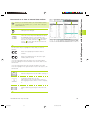
4.3 Standard File Management
Deleting a file
Calling the file manager
<
Use the arrow keys to move the highlight to the file you wish to
delete:
Move the highlight up or down.
<
Delete a file: Press the DELETE soft key
Delete ........ file ?
<
Press the YES soft key to confirm, or
the NO soft key to abort.
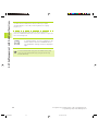
Copying a file
Calling the file manager
<
Use the arrow keys to move the highlight to the file you wish to
copy:
Move the highlight up or down.
<
Copy a file: Press the COPY soft key
Target file =
<
Enter the name of the new file and confirm your entry with the
ENT key or EXECUTE soft key. A status window appears on the
TNC, informing about the copying progress. As long as the TNC
is copying, you can no longer work, or
If you wish to copy very long programs, enter the new file name
and confirm with the PARALLEL EXECUTE soft key. The file will
now be copied in the background, so you can continue to work
while the TNC is copying.
HEIDENHAIN TNC 426, TNC 430
Ekap4.pm6
37
37
28.06.2006, 11:34
4.3 Standard File Management
Data transfer to or from an external data medium
Before you can transfer data to an external data medium,
you must set the interface (see „Section 12.4 Setting the
Data Interfaces“).
Calling the file manager
<
Activate data transfer: press the EXT soft key. In
the left half of the screen, the TNC shows all of
the files that are stored on the TNC, and in the
right half of the screen, all of the files that are
stored on the external data medium.
<
Use the arrow keys to highlight the file(s) that you want to
transfer:
Move the highlight up and down within a
window
Move the highlight from the left to the right
window, and vice versa.
If you are transferring from the TNC to the external medium,
move the highlight in the left window onto the file that is to be
transferred.
If you are transferring from the external medium to the TNC,
move the highlight in the right window onto the file that is to be
transferred.
<
Tagging functions
Transfer a single file: Press the COPY soft key, or
Transfer several files: Press
TAG (marking functions, see table on right), or
Soft key
Tag a single file
Tag all files
Untag a single file
transfer all files by pressing the TNC EXT soft
key
Copy all tagged files
<
38
Ekap4.pm6
Untag all files
4 Programming: Fundamentals of NC, File Management,
Programming Aids, Pallet Management
38
28.06.2006, 11:34
4.3 Standard File Management
Confirm with the EXECUTE or with the ENT key. A status
window appears on the TNC, informing about the copying
progress, or
If you wish to transfer more than one file or longer files,
press the PARALLEL EXECUTE soft key. The TNC then copies the
file in the background.
<
To stop transfer, press the TNC soft key. The
standard file manager window is displayed
again.
Selecting one of the last 10 files selected.
Calling the file manager
<
Display the last 10 files selected: Press LAST
FILES soft key
Use the arrow keys to move the highlight to the file you wish to
select:
Move the highlight up or down.
<
or
Select a file: Press the SELECT soft key
or ENT
HEIDENHAIN TNC 426, TNC 430
Ekap4.pm6
39
39
28.06.2006, 11:34
4.3 Standard File Management
Renaming a file
Calling the file manager
<
Use the arrow keys to move the highlight to the file you wish to
rename:
Move the highlight up or down.
<
To rename the file, press the RENAME key.
Target file =
<
Enter the name of the new file and confirm your entry with the
ENT key or EXECUTE soft key.
Convert an FK program into
HEIDENHAIN conversational format
Calling the file manager
<
Use the arrow keys to move the highlight to the file you wish to
convert:
Move the highlight up or down.
<
Press the CONVERT
FK -> H to select the convert function
Target file =
<
Enter the name of the new file and confirm your entry with the
ENT key or EXECUTE soft key.
40
Ekap4.pm6
4 Programming: Fundamentals of NC, File Management,
Programming Aids, Pallet Management
40
28.06.2006, 11:34
4.3 Standard File Management
Protect file / Cancel file protection
Calling the file manager
<
Use the arrow keys to move the highlight to the file you wish to
protect or whose protection you wish to cancel:
Move the highlight up or down.
<
Press the PROTECT soft key to enable file
protection The file now has status P, or
To cancel file protection, press the UNPROTECT
soft key. The P status is canceled.
HEIDENHAIN TNC 426, TNC 430
Ekap4.pm6
41
41
28.06.2006, 11:34
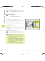
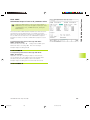
4.4 File Management with Additional Functions
4.4 File Management with Additional
Functions
Select the file manager with additional functions if you
wish to store files in various different directories.
Set the MOD function PGM MGT (see Section 12.6) to
Enhanced!
See also Section „4.2 File Management: Fundamentals“!
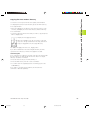
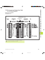
Directories
To ensure that you can easily find your files, we recommend that
you organize your hard disk into directories. You can divide a
directory up into further directories, which are called subdirectories.
The TNC can manage up to 6 directory levels!
If you save more than 512 files in one directory, the TNC
no longer sorts them alphabetically!
Directory names
The name of a directory can contain up to 8 characters and does not
have an extension. If you enter more than 8 characters for the
directory name, the TNC will shorten the name to 8 characters.
Paths
TNC:\
A path indicates the drive and all directories and subdirectories
under which a file is saved. The individual names are separated by
the symbol “\”.
AUFTR1
NCPROG
Example: On drive TNC:\, the directory AUFTR1 was created. Under
this directory, the subdirectory NCPROG was created, and the part
program PROG1.H copied into this subdirectory. The part program
now has the following path:
WZTAB
A35K941
TNC:\AUFTR1\NCPROG\PROG1.H
ZYLM
The chart at right illustrates an example of a directory display with
different paths.
TESTPROG
HUBER
KAR25T
42
Ekap4.pm6
4 Programming: Fundamentals of NC, File Management,
Programming Aids, Pallet Management
42
28.06.2006, 11:34
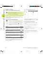
4.4 File Management with Additional Functions
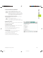
Overview: Functions of the expanded file manager
Function
Soft key
Copy (and convert) individual files
Display a specific file type
Display the last 10 files that were selected
Erase a file or directory
Tag a file
Renaming a file
Convert an FK program into
HEIDENHAIN conversational format
Protect a file against editing and erasure
Cancel file protection
Network drive management (Ethernet option only)
Copying a directory
Display all the directories of a particular drive
Delete directory with all its subdirectories
HEIDENHAIN TNC 426, TNC 430
Ekap4.pm6
43
43
28.06.2006, 11:34
4.4 File Management with Additional Functions
Calling the file manager
Press the PGM MGT:
The TNC displays the file management window
(see Fig. at top right for default setting. If the
TNC displays a different screen layout, press the
WINDOW soft key)
The narrow window at left shows three drives . If the TNC is
connected to a network, it also displayed the connected network
drives. Drives designate devices with which data are stored or
transferred. One drive is the hard disk of the TNC. Other drives are
the interfaces (RS232, RS422, Ethernet), which can be used, for
example, to connect a personal computer. The selected (active)
drive is shown in a different color.
In the lower part of the narrow window the TNC shows all
directories of the selected drive. A drive is always identified by a
file symbol to the left and the directory name to the right. The TNC
displays a subdirectory to the right of and below its parent directory.
The selected (active) directory is depicted in a different color.
The wide window at on the right side shows all the files that are
stored in the selected directory. Each file is shown with additional
information that is illustrated in the table on the next page.
44
Ekap4.pm6
Display
Meaning
FILE NAME
Name with max. 16 characters
and file type
BYTE
File size in bytes
STATUS
E
Property of the file:
Program is selected
Programming and Editing
mode of operation
S
Program is selected
Test Run mode of operation
M
Program is in the Program
Run mode of operation.
P
File is protected against
editing and erasure
(Protected)
DATE
Date the file
was last changed
TIME
Time the file
was last changed
4 Programming: Fundamentals of NC, File Management,
Programming Aids, Pallet Management
44
28.06.2006, 11:34
4.4 File Management with Additional Functions
To select drives, directories and files:
Calling the file manager
<
With the arrow keys or the soft keys, you can move the highlight to
the desired position on the screen:
Move the highlight from the left to the right
window, and vice versa.
Move the highlight up and down within a
window
Move the highlight one page up or
down within a window
1st step: select drive:
Move the highlight to the desired drive in the left window:
<
or
Select drive: Press the SELECT soft key
or ENT
2nd step: select directory:
Move the highlight to the desired directory in the left window —
the right window automatically shows all files stored in the
highlighted directory.
HEIDENHAIN TNC 426, TNC 430
Ekap4.pm6
45
45
28.06.2006, 11:34
4.4 File Management with Additional Functions
3rd step: select a file:
Press the SELECT TYPE soft key
Press the soft key for the desired file type, or
To display all files, press the SHOW ALL soft key
or
4*.H
use wildcard characters, e.g., to show all files of
the file type .H that begin with 4.
Move the highlight to the desired file in the right window
<
or
The selected file is opened in the
operating mode from which you have
the called file manager: Press ENT or
the SELECT soft key.
To create a new directory (only possible on the
TNC's hard disk drive):
Move the highlight in the left window to the directory in which
you want to create a subdirectory.
<
NEW
Enter the new file name, and confirm with ENT.
Create \NEW directory ?
<
Press the YES soft key to confirm, or
the NO soft key to abort.
46
Ekap4.pm6
4 Programming: Fundamentals of NC, File Management,
Programming Aids, Pallet Management
46
28.06.2006, 11:34
4.4 File Management with Additional Functions
Copying a file
ú Move the highlight to the file you wish to copy.
ú Press the COPY soft key to select the copying
function.
ú Enter the name of the destination file and confirm your entry with
the ENT key or EXECUTE soft key: The TNC copies the file into the
active directory. The original file is retained.
Press the PARALLEL EXECUTE soft key to copy the file in the
background. Copying in the background permits you to continue
working while the TNC is copying. This can be useful if you are
copying very large files that take a long time. While the TNC is
copying in the background you can press the INFO PARALLEL
EXECUTE soft key (under MORE FUNCTIONS, second soft-key
row) to check the progress of copying.
Copying a table
If you are copying tables, you can overwrite individual lines or
columns in the target table with the REPLACE FIELDS soft key.
Prerequisites:
■ The target table must exist.
■ The file to be copied must only contain the columns or lines you
want to replace.
Example:
With a tool presetter you have measured the length and radius of
10 new tools. The tool presetter then generates the tool table
TOOL.T with 10 lines (for the 10 tools) and the columns
■ Tool number
■ Tool length
■ Tool radius
If you wish to copy this file to the TNC, the TNC asks if you wish to
overwrite the existing TOOL.T tool table:
■ If you press the YES soft key, the TNC will completely overwrite
the current TOOL.T tool table. After this copying process the new
TOOL.T table consists of 10 lines. The only remaining columns in
the table are tool number, tool length and tool radius.
■ If you press the REPLACE FIELDS soft key, the TNC merely
overwrites the first 10 lines of the columns number, length and
radius in the TOOL.T file. The data of the other lines and columns
is not changed.
Copying a directory
Move the highlight in the left window onto the directory you want
to copy. Press the COPY DIR soft key instead of the COPY soft key.
Subdirectories are also copied at the same time.
HEIDENHAIN TNC 426, TNC 430
Ekap4.pm6
47
47
28.06.2006, 11:34
4.4 File Management with Additional Functions
Selecting one of the last 10 files selected.
Calling the file manager
<
Display the last 10 files selected: Press LAST
FILES soft key
Use the arrow keys to move the highlight to the file you wish to
select:
Move the highlight up or down.
<
or
Select a file: Press the SELECT soft key
or ENT
Deleting a file
ú Move the highlight to the file you want to delete.
ú To select the erasing function, press the DELETE soft
key.
The TNC inquires whether you really intend to erase
the file.
ú To confirm, press the YES soft key;
To abort erasure, press the NO soft key.
Erase a directory
ú Erase all files and subdirectories stored in the directory that you
wish to erase.
ú Move the highlight to the directory you want to delete.
ú To select the erasing function, press the DELETE soft
key. The TNC inquires whether you really intend to
erase the directory.
ú To confirm, press the YES soft key;
To abort erasure, press the NO soft key.
48
Ekap4.pm6
4 Programming: Fundamentals of NC, File Management,
Programming Aids, Pallet Management
48
28.06.2006, 11:34
Tagging functions
Some functions, such as copying or erasing files, can not only be
used for individual files, but also for several files at once. To tag
several files, proceed as follows:
Tagging single files
4.4 File Management with Additional Functions
Tagging files
Soft key
Tag all files in the
directory
Move the highlight to the first file.
Untag a single file
<
To display the marking functions, press the TAG
soft key.
<
Untag all files
Copy all tagged files
Tag a file by pressing the TAG FILE soft key.
<
Move the highlight to the next file you wish to tag:
<
You can tag several files in this way, as desired.
To copy the tagged files, press the COPY TAG
soft key, or
Delete the tagged files by
pressing END to end the marking
function, and then DELETE to delete
the tagged files.
Renaming a file
ú Move the highlight to the file you wish to rename.
ú Select the renaming function.
ú Enter the new file name; the file type cannot be
changed.
ú To execute renaming, press the ENT key.
HEIDENHAIN TNC 426, TNC 430
Ekap4.pm6
49
49
28.06.2006, 11:34
4.4 File Management with Additional Functions
Additional Functions
Protecting a file/Canceling file protection
ú Move the highlight to the file you want to protect.
ú To select the additional functions, press the MORE
FUNCTIONS key.
ú To enable file protection, press the PROTECT soft key.
The file now has status P.
To cancel file protection, proceed in the same way using the
UNPROTECT soft key.
Converting an FK program into HEIDENHAIN conversational
format
ú Move the highlight to the file you want to convert.
ú To select the additional functions, press the MORE
FUNCTIONS key.
ú To select the converting function, press the CONVERT
FK->H soft key
ú Enter the name of the destination file.
ú To execute conversion, press the ENT key.
Erase a directory together with all its subdirectories and files.
ú Move the highlight in the left window onto the directory you want
to erase.
ú To select the additional functions, press the MORE
FUNCTIONS key.
ú Press DELETE ALL to erase the directory together
with its subdirectories.
ú To confirm, press the YES soft key;
To abort erasure, press the NO soft key.
50
Ekap4.pm6
4 Programming: Fundamentals of NC, File Management,
Programming Aids, Pallet Management
50
28.06.2006, 11:34
4.4 File Management with Additional Functions
Data transfer to or from an external data medium
Before you can transfer data to an external data medium,
you must set the interface (see „Section 12.4 Setting the
Data Interfaces“).
Calling the file manager
<
Select the screen layout for data transfer: press
the WINDOW soft key. In the left half of the
screen, the TNC shows all of the files that are
stored on the TNC, and in the right half of the
screen, all of the files that are stored on the
external data medium.
<
Use the arrow keys to highlight the file(s) that you want to
transfer:
Move the highlight up and down within a
window
Move the highlight from the left to the right
window, and vice versa.
If you are transferring from the TNC to the external medium,
move the highlight in the left window onto the file that is to be
transferred.
If you are transferring from the external medium to the TNC,
move the highlight in the right window onto the file that is to be
transferred.
<
Transfer a single file: Press the COPY soft key, or
To transfer several files, use the
TAG soft key (in the second soft-key row, see
also Tagging functions earlier on in this chapter),
or
transfer all files by pressing the TNC EXT soft
key
<
HEIDENHAIN TNC 426, TNC 430
Ekap4.pm6
51
51
28.06.2006, 11:34
4.4 File Management with Additional Functions
Confirm with the EXECUTE or with the ENT key. A status
window appears on the TNC, informing about the copying
progress, or
If you wish to transfer more than one file or longer files,
press the PARALLEL EXECUTE soft key. The TNC then copies the
file in the background.
<
To end data transfer, move the highlight into left
window and then press the WINDOW soft key.
The standard file manager window is displayed
again.
To select another directory, press the PATH soft key and
then select the desired directory using the arrow keys
and the ENT key!
52
Ekap4.pm6
4 Programming: Fundamentals of NC, File Management,
Programming Aids, Pallet Management
52
28.06.2006, 11:34
4.4 File Management with Additional Functions
Copying files into another directory
ú Select the screen layout with the two equally sized windows.
ú To display directories in both windows, press the PATH soft key.
In the right window:
ú Move the highlight to the directory into which you wish to copy
the files, and display the files in this directory with the ENT key
In the left window:
ú Select the directory with the files that you wish to copy and press
ENT to display them.
ú Display the file tagging functions.
ú Move the highlight to the file you want to copy and
tag it. You can tag several files in this way, as desired.
ú Copy the tagged files into the target directory.
For additional tagging functions see „Tagging files“.
If you have marked files in the left and right windows, the TNC
copies from the directory in which the highlight is located.
Overwriting files
If you copy files into a directory in which other files are stored under
the same name, the TNC will ask whether the files in the target
directory should be overwritten:
ú Press the YES soft key to overwrite all files, or
ú Press the NO soft key if no file is to be overwritten
ú To confirm each file separately before overwriting it, press the
CONFIRM key.
If you wish to overwrite a protected file, this must also be
confirmed or aborted separately.
HEIDENHAIN TNC 426, TNC 430
Ekap4.pm6
53
53
28.06.2006, 11:34
4.4 File Management with Additional Functions
The TNC in a network
(applies only for Ethernet interface option)
To connect the Ethernet card to your network, refer to
Chapter ”12.5 Ethernet Interface”!
The TNC logs error messages during network operation
(see section ”12.5 Ethernet Interface”).
If the TNC is connected to a network, the directory window displays
up to 7 drives (see screen at upper right). All the functions
described above (selecting a drive, copying files, etc.) also apply to
network drives, provided that you have been given the
corresponding rights.
Connecting and disconnecting network drives
ú To select the program management: Press the PGM
MGT key. If necessary, press the WINDOW soft key to
set up the screen as it is shown to the upper right.
ú To manage the network drives: Press the ”Network”
soft key. In the right-hand window the TNC shows
the network drives available for access. With the
following soft keys you can define the connection for
each drive.
Printing the file with a network printer
If you have defined a network printer (see section
”12.5 Ethernet Interface”), you can print the files
directly:
ú To call the file manager, press the PGM MGT key.
ú Move the highlight to the file you wish to print.
Function
Soft key
Establish network connection. If the connection
is active, the TNC shows an M in the Mnt column.
You can connect up to 7 additional drives with the TNC.
Delete network connection
Automatically establish connection whenever the
TNC is switched on. The TNC show in the Auto column
an A if the connection is established automatically.
ú Press the COPY soft key.
ú Press the PRINT soft key: If you have define only
one printer, the TNC will print the file
immediately.
If you have defined more than one printer, the
TNC opens a window listing all defined printers.
Use the arrow keys to select the desired printer,
then press ENT.
Do not network connection automatically when
the TNC is switched on
It may take some time to mount a network device. At the upper
right of the screen the TNC displays [READ DIR] to indicate that a
connection is being established. The maximum data transmission
rate lies between 200 and 1000 kilobaud, depending on the file
type being transmitted.
54
Ekap4.pm6
4 Programming: Fundamentals of NC, File Management,
Programming Aids, Pallet Management
54
28.06.2006, 11:34
Organization of an NC program in HEIDENHAIN
conversational format.
A part program consists of a series of program blocks. The figure at
right illustrates the elements of a block.
The TNC numbers the blocks in ascending sequence.
Block:
10 L X+10 Y+5 R0 F100 M3
The first block of a program is identified by “BEGIN PGM,” the
program name and the active unit of measure.
The subsequent blocks contain information on:
■ The blank form
Path function
Words
Block number
■ Tool definitions, tool calls
■ Feed rates and spindle speeds as well as
■ Path contours, cycles and other functions
The last block of a program is identified by “END PGM,” the program name and the active unit of measure.
Defining the blank form — BLK FORM
Immediately after initiating a new program, you define a cuboid
workpiece blank. This definition is needed for the TNC’s graphic
simulation feature. The sides of the workpiece blank lie parallel to
the X, Y and Z axes and can be up to 100 000 mm long. The blank
form is defined by two of its corner points:
Z
MAX
Y
■ MIN point: the smallest X, Y and Z coordinates of the blank form,
entered as absolute values.
X
■ MAX point: the largest X, Y and Z coordinates of the blank form,
entered as absolute or incremental values.
You only need to define the blank form if you wish to run
a graphic test for the program!
MIN
The TNC can only display the graphic if the ratio of the
shortest to the longest side of the BLK FORM is less than
1 : 64.
HEIDENHAIN TNC 426, TNC 430
Ekap4.pm6
55
55
28.06.2006, 11:34
4.5 Creating and Writing Programs
4.5 Creating and Writing Programs
4.5 Creating and Writing Programs
Creating a new part program
You always enter a part program in the Programming and Editing
mode of operation.
Program initiation in an example:
Select the Programming and Editing mode of
operation.
<
To call the file manager, press the PGM MGT key.
<
Select the directory in which you wish to store the new program
File name = OLD.H
<
NEW
Enter the new program name and confirm your
entry with the ENT key.
To select the unit of measure, press the MM or
INCH soft key. The TNC switches the screen
layout and initiates the dialog for defining the
BLK FORM.
Working spindle axis X/Y/Z ?
<
Enter the spindle axis.
If you do not wish to define a blank form,
cancel the dialog with the DEL key.
Def BLK FORM: Min-corner ?
<
0
Enter in sequence the X, Y and Z coordinates of
the MIN point.
0
-40
Def BLK FORM: Max-corner ?
<
100
Enter in sequence the X, Y and Z coordinates of
the MAX point.
100
0
56
Ekap4.pm6
4 Programming: Fundamentals of NC, File Management,
Programming Aids, Pallet Management
56
28.06.2006, 11:34
4.5 Creating and Writing Programs
The program blocks window shows the following BLK FORM
definition
0
1
2
3
BEGIN PGM NEW MM
BLK FORM 0.1 Z X+0 Y+0 Z-40
BLK FORM 0.2 X+100 Y+100 Z+0
END PGM NEW MM
Program begin, name, unit of measure
Tool axis, MIN point coordinates
MAX point coordinates
Program end, name, unit of measure
The TNC automatically generates the block numbers as well as the
BEGIN and END blocks.
Programming tool movementstool movements in
conversational format
To program a block, initiate the dialog by pressing a function key. In
the screen headline, the TNC then asks you for all the information
necessary to program the desired function.
Example of a dialog
Initiate the dialog.
Coordinates ?
<
10
Enter the target coordinate for the X axis.
<
5
Enter the target coordinate for the Y axis, and go
to the next question with ENT.
Radius comp. RL/RR/no comp. ?
<
Enter “No radius compensation” and go to the
next question with ENT.
Feed rate F=? / F MAX = ENT
<
100
Enter a feed rate of 100 mm/min for this path
contour; go to the next question with ENT.
Miscellaneous function M ?
<
3
Enter the miscellaneous function M3 “spindle
ON”; pressing the ENT key will terminate this
dialog.
Functions during the dialog
Key
Ignore the dialog question
End the dialog immediately
Abort the dialog and erase the block
Functions for setting the feed rate Soft key
Rapid traverse
Traverse feed rate automatically
calculated in TOOL CALL block
The program blocks window will display the following line:
3 L X+10 Y+5 R0 F100 M3
HEIDENHAIN TNC 426, TNC 430
Ekap4.pm6
57
57
28.06.2006, 11:34
4.5 Creating and Writing Programs
Editing a program
Selecting blocks or words
While you are creating or editing a part program, you can select any
desired line in the program or individual words in a block with the
arrow keys or the soft keys (see table at right).
Go to the previous page
Soft keys/keys
Go to the next page
Inserting blocks at any desired location
ú Select the block after which you want to insert a new block and
initiate the dialog.
Jump to beginning of program
Editing and inserting words
ú Select a word in a block and overwrite it with the new one. The
plain-language dialog is available while the word is highlighted.
Jump to end of program
Move from one block to the next
ú To accept the change, press the END key.
If you want to insert a word, press the horizontal arrow key
repeatedly until the desired dialog appears. You can then enter the
desired value.
Select individual words in a
block
Looking for the same words in different blocks
Set the AUTO DRAW soft key to OFF.
Erasing blocks and words
To select a word in a block, press the arrow keys
repeatedly until the highlight is on the desired
word.
Key
Set the selected word to zero
Erase an incorrect number
Clear a (non-blinking) error message
Select a block with the arrow keys.
Delete the selected word
The word that is highlighted in the new block is the same as the
one you selected previously.
Finding any text
ú To select the search function, press the FIND soft key.
The TNC displays the dialog prompt FIND TEXT:
ú Enter the text that you wish to find.
Delete the selected block
Erase cycles and program sections:
First select the last block of the cycle
or program section to be erased, then
erase with the DEL key.
ú To find the text, press the EXECUTE soft key.
58
Ekap4.pm6
4 Programming: Fundamentals of NC, File Management,
Programming Aids, Pallet Management
58
28.06.2006, 11:34
Function
To copy a program section, proceed as follows:
Switch off marking function
4.5 Creating and Writing Programs
Marking, copying, deleting and inserting program sections
The TNC provides certain functions (listed in table at right) for
copying program sections within an NC program or into another NC
program.
Soft key
Switch on marking function
ú Select the soft-key row using the marking function.
ú Select the first (last) block of the section you wish to copy.
Delete marked block
ú To mark the first (last) block: Press the SELECT BLOCK soft key.
The TNC then highlights the first character of the block and
superimposes the soft key CANCEL SELECTION.
Insert block that is stored in
the buffer memory
ú Move the highlight to the last (first) block of the program section
you wish to copy or delete. The TNC shows the marked blocks in
a different color. You can end the marking function at any time by
pressing the CANCEL SELECTION soft key.
Copy marked block
ú To copy the selected program section: Press the COPY BLOCK
soft key, and to delete the selected section: Press the DELETE
BLOCK soft key. The TNC stores the selected block.
ú Using the arrow keys, select the block after which you wish to
insert the copied (deleted) program section.
To insert the section into another program, select the
corresponding program using the File Manager and then
mark the block after which you wish to insert the copied
block.
ú To insert the block: Press the INSERT BLOCK soft key
HEIDENHAIN TNC 426, TNC 430
Ekap4.pm6
59
59
28.06.2006, 11:34
4.6 Interactive Programming Graphics
4.6 Interactive Programming Graphics
While you are writing the part program, you can have the TNC
generate a graphic illustration of the programmed contour.
To generate/not generate graphics during programming:
ú To switch the screen layout to displaying program blocks to the
left and graphics to the right, press the SPLIT SCREEN key and
PGM + GRAPHICS soft key.
ú Set the AUTO DRAW soft key to ON. While you are
entering the program lines, the TNC generates each
path contour you program in the graphics window in
the right screen half.
If you do not wish to have graphics generated during programming,
set the AUTO DRAW soft key to OFF.
Even when AUTO DRAW is switched ON, graphics are not
generated for program section repeats.
Functions
Generating a graphic for an existing program
Generate interactive graphic blockwise
ú Use the arrow keys to select the block up to which you want the
graphic to be generated, or press GOTO and enter the desired
block number.
ú To generate graphics, press the RESET + START soft
Soft key
Generate a complete graphic
or complete it after
RESET + START
key.
Additional functions are listed in the table at right.
Interrupt interactive graphics
This soft key only appears while the
TNC generates the interactive graphics
Block number display ON/OFF
ú Shift the soft-key row (see figure at right)
ú To show block numbers: Set
the SHOW OMIT BLOCK NR. soft key to SHOW.
ú To omit block numbers: Set
the SHOW OMIT BLOCK NR. soft key to OMIT.
To erase the graphic:
ú Shift the soft-key row (see figure at right)
ú Delete graphic: Press CLEAR GRAPHIC soft key
60
Ekap4.pm6
4 Programming: Fundamentals of NC, File Management,
Programming Aids, Pallet Management
60
28.06.2006, 11:34
4.7 Structuring Programs
Magnifying or reducing a detail
You can select the graphics display by selecting a detail with the
frame overlay. You can now magnify or reduce the selected detail.
ú Select the soft-key row for detail magnification/reduction
(second row, see figure at right)
The following functions are available:
Function
Soft key
Show and move the frame overlay.
Press and hold the desired soft key
to move the frame overlay.
Reduce the frame overlay — press and
hold the soft key to reduce the detail
Enlarge the frame overlay — press and
hold the soft key to magnify the detail
ú With the WINDOW DETAIL soft key, Confirm the
selected area.
With the WINDOW BLK FORM soft key, you can restore the original
section.
4.7 Structuring Programs
This TNC function enables you to comment part programs in
structuring blocks. Structuring blocks are short texts with up to 244
characters and are used as comments or headlines for the subsequent program lines.
With the aid of appropriate structuring blocks, you can organize long
and complex programs in a clear and comprehensible way. This
function is particularly convenient if you want to change the program later. Structuring blocks can be inserted into the part program
at any point. They can also be displayed in a separate window, and
edited or added to, as desired. A second level is provided for
subdividing a structuring block. The texts in this level are indented.
To display the program structure window / change the active
window:
ú To display the program structure window, select the
screen display PGM+SECTS block
ú To change the active window, press the CHANGE
WINDOW soft key.
HEIDENHAIN TNC 426, TNC 430
Ekap4.pm6
61
61
28.06.2006, 11:34
4.8 Adding Comments
To insert a structuring block in the (left) program window
ú Select the block after which the structuring block is to be inserted.
ú Press the INSERT SECTION soft key.
ú Enter the structuring text with the alphabetic
keyboard.
If necessary, change the level with the CHANGE LEVEL soft key.
To insert a structuring block in the (right) structure window
ú Select the structuring block after which the new block is to be
inserted.
ú Enter the text with the alphabetic keyboard — the TNC
automatically inserts the new block.
Selecting blocks in the program structure window
If you are scrolling through the program structure window block by
block, the TNC at the same time automatically moves the
corresponding NC blocks in the program window. This way you can
quickly skip large program sections.
4.8 Adding Comments
You can add comments to any desired block in the part program to
explain program steps or make general notes. There are three
possibilities to add comments:
1. To enter comments during programming:
ú Enter the data for a program block, then press the semicolon key
“;” on the alphabetic keyboard — the TNC displays the dialog
prompt
COMMENT ?
ú Enter your comment and conclude the block by pressing the END
key.
2. To insert comments after program entry:
ú Select the block to which a comment is to be added.
ú Select the last word in the block with the right arrow key:
A semicolon appears at the end of the block and the TNC displays
the dialog prompt COMMENT ?
ú Enter your comment and conclude the block by pressing the END
key.
3. To enter a comment in a separate block:
ú Select the block after which the comment is to be inserted.
ú Initiate the programming dialog with the semicolon key “;” on
the alphabetic keyboard.
ú Enter your comment and conclude the block by pressing the END
key.
62
Ekap4.pm6
4 Programming: Fundamentals of NC, File Management,
Programming Aids, Pallet Management
62
28.06.2006, 11:34
4.9 Creating Text Files
4.9 Creating Text Files
You can use the TNC’s text editor to write and edit texts. Typical
applications:
■ Recording test results
■ Documenting working procedures
■ Creating formularies
Text files are type .A files (ASCII files). If you want to edit other
types of files, you must first convert them into type .A files.
Opening and exiting text files
ú Select the Programming and Editing mode of operation.
ú To call the file manager, press the PGM MGT key.
ú To display type .A files, press the SELECT TYPE and then the
SHOW .A soft keys.
ú Select a file and open it with the SELECT soft key or ENT key,
or create a new file by entering the new file name and confirming
your entry with the ENT key.
To leave the text editor, call the file manager and select a file of a
different file type, for example a part program.
Editing texts
The first line of the text editor is an information headline which
displays the file name, and the location and writing mode of the
cursor:
File:
Name of the text file
Line:
Line in which the cursor is presently located
Column:
Column in which the cursor is presently located
Insert:
Insert new text, pushing the existing text to the
right
Overwrite:
Write over the existing text, erasing it where it is
replaced with the new text.
The text is inserted or overwritten at the location of the cursor. You
can move the cursor to any desired position in the text file by
pressing the arrow keys.
The line in which the cursor is presently located is depicted in a
different color. A line can have up to 77 characters. To start a new
line, press the RET key or the ENT key.
Cursor movements
Soft key
Move one word to the right
Move one word to the left
Go to the next screen page
Go to the previous screen page
Go to beginning of file
Go to end of file
Editing functions
Key
Begin a new line
Erase the character to the left
of the cursor
Insert a blank space
Switch between upper and
lower case letters
HEIDENHAIN TNC 426, TNC 430
Ekap4.pm6
63
+
63
28.06.2006, 11:34
4.9 Creating Text Files
Erasing and inserting characters, words and lines
Delete functions
With the text editor, you can erase words and even lines, and insert
them at any desired location in the text. See the table at right.
Delete and temporarily store a line
To move a word or line to a different location:
ú Move the cursor to the word or line you wish to erase and insert
at a different place in the text.
Delete and temporarily store a word
Soft key
Delete and temporarily store a character
ú Press the DELETE WORD or DELETE LINE soft key: The text is
deleted and stored temporarily.
Insert a line or word from temporary
storage
ú Move the cursor to the location where you wish insert the text,
and press the RESTORE LINE/WORD soft key.
Editing text blocks
You can copy and erase text blocks of any size, and insert them at
other locations. Before carrying out any of these editing functions,
you must first select the desired text block:
ú To select a text block, move the cursor to the first character of the
text you wish to select.
ú Press the SELECT BLOCK soft key.
ú Move the cursor to the last character of the text you
wish to select. You can select whole lines by moving
the cursor up or down directly with the arrow keys —
the selected text is shown in a different color.
After selecting the desired text block, you can edit the text with the
following soft keys:
Function
Soft key
Delete the selected text and
store temporarily
Store marked block temporarily
without erasing (copy )
If necessary, you can now insert the temporarily stored block at a
different location
ú Move the cursor to the location where you want to insert the
temporarily stored text block.
ú Press the INSERT BLOCK soft key _ the text block in
inserted.
You can insert the temporarily stored text block as often as desired.
64
Ekap4.pm6
4 Programming: Fundamentals of NC, File Management,
Programming Aids, Pallet Management
64
28.06.2006, 11:34
4.9 Creating Text Files
To transfer the selected text to a different file:
ú Select the text block as described previously.
ú Press the APPEND TO FILE soft key — the TNC
displays the dialog prompt Destination file =
ú Enter the path and name of the target file. The TNC
appends the selected text to the end of the specified
file. If no target file with the specified name is found,
the TNC creates a new file with the selected text.
To insert another file at the cursor position:
ú Move the cursor to the location in the text where you wish to
insert another file.
ú Press the READ FILE soft key.
The TNC displays the dialog prompt File name =
ú Enter the path and name of the file you want to insert.
Finding text sections
With the text editor, you can search for words or character strings in
a text. Two functions are available:
1. Finding the current text
The search function is to find the next occurrence of the word in
which the cursor is presently located:
ú Move the cursor to the desired word.
ú To select the search function, press the FIND soft key.
ú Press the FIND CURRENT WORD soft key
2. Finding any text
ú To select the search function, press the FIND soft key.
The TNC displays the dialog prompt Find text:
ú Enter the text that you wish to find.
ú To find the text, press the EXECUTE soft key.
To leave the search function, press the END soft key.
HEIDENHAIN TNC 426, TNC 430
Ekap4.pm6
65
65
28.06.2006, 11:34
4.10 Integrated Pocket Calculator
4.10 Integrated Pocket Calculator
The TNC features an integrated pocket calculator with the basic
mathematical functions.
With the CALC key you can open and close an additional window
for calculations. You can move the window to any desired location
on the TNC screen with the arrow keys.
0
The calculator is operated with short commands through the
alphabetic keyboard. The commands are shown in a special color in
the calculator window:
Mathematical function
Command
Addition
Subtraction
Multiplication
Division
Sine
Cosine
Tangent
Arc sine
Arc cosine
Arc tangent
Powers
Square root
Inversion
Parenthetic calculations
p (3.14159265359)
Display result
+
–
*
:
S
C
T
AS
AC
AT
^
Q
/
()
P
=
7
8
9
:
4
5
6
PI
1
2
3
=
0
.
+
ARC SIN COS TAN
+
–
∗
X^Y SQR 1/X
(
)
CE
–
If you are writing a program and the programming dialog is active,
you can use the actual-position-capture key to transfer the result to
the highlight position in the current block.
66
Ekap4.pm6
4 Programming: Fundamentals of NC, File Management,
Programming Aids, Pallet Management
66
28.06.2006, 11:34
4.11 Immediate Help for NC Error Messages
4.11 HELP for NC error messages
The TNC automatically generates error messages when it detects
problems such as
■
■
■
■
Incorrect data input
Logical errors in the program
Contour elements that are impossible to machine
Incorrect use of the touch probe system
An error message that contains a program block number was
caused by an error in the indicated block or in the preceding block.
The TNC error messages can be canceled with the CE key, after the
cause of the error has been removed.
If you require more information on a particular error message, press
the HELP key. A window is then superimposed where the cause of
the error is explained and suggestions are made for correcting the
error.
Display HELP
if an error message appears at the top of screen:
ú To display Help, press the HELP key
ú Read the description of the error and the possibilities
for correcting it. Close the Help window with the CE,
thus canceling the error message
ú Remove the cause of the error as described in the
Help window.
The TNC displays the Help text automatically if the error message is
flashing. The TNC needs to be restarted after blinking error
messages. To restart the TNC, press the END key and hold for two
seconds.
HEIDENHAIN TNC 426, TNC 430
Ekap4.pm6
67
67
28.06.2006, 11:34
4.12 Managing Pallet Tables
4.12 Managing Pallet Tables
Pallet table management is a machine-dependent
function. The standard functional range will be described
in the following. Refer to your machine manual for more
information.
Pallet tables are used for machining centers with pallet changer:
The pallet table calls the part programs that are required for the
different pallets, and activates datum shifts or datum tables.
You can also use pallet tables to run in succession several programs
that have different datums.
Pallet tables contain the following information:
■ PAL/PGM (entry obligatory): Identification for pallet or NC program
(select with ENT or NO ENT)
■ NAME (entry obligatory): Pallet or program name. The machine
tool builder determines the pallet name (see Machine Manual).
The program name must be stored in the same directory as the
pallet table. Otherwise you must enter the full path name for the
program.
■ DATUM (entry optional): Name of the datum table. The datum
Function
Soft key
Select beginning of table
Select end of table
table must be stored in the same directory as the pallet table.
Otherwise you must enter the full path name for the datum table.
Datums from the datum table can be activated in the NC program
with Cycle 7 DATUM SHIFT
■ X, Y, Z (entry optional; other axes also possible): For pallet names,
the programmed coordinates are referenced to the machine
datum. For NC programs, the programmed coordinates are
referenced to the pallet datum. These entries overwrite the
datum that you last set in the Manual mode of operation. With the
miscellaneous function M104 you can reactivate the datum that
was last set. With the ”actual-position-capture” key, the TNC
opens a window that enables you to have the TNC enter various
points as datums (see next page):
Select previous page in table
Select next page in table
Insert the last line in the table
Delete the last line in the table
Go to the beginning of the next line
Add the entered number of lines
to the end of the table
Copy the highlighted field
(2nd soft-key row)
Insert the copied field
(2nd soft-key row)
68
Ekap4.pm6
4 Programming: Fundamentals of NC, File Management,
Programming Aids, Pallet Management
68
28.06.2006, 11:34
Meaning
Actual values
Enter the coordinates of the current
tool position relative to the active
coordinate system.
Enter the coordinates of the current
tool position relative to the machine
datum.
Enter the coordinates relative to the
active coordinate system of the datum
last probed in the Manual operating
mode.
Enter the coordinates relative to the
machine datum of the datum last
probed in the Manual operating mode.
Reference values
ACTL measured values
REF measured values
With the arrow keys and ENT, select the position that you wish to
confirm. Then press the ALL VALUES soft key so that the TNC saves
the respective coordinates of all active axes in the pallet table. With
the PRESENT VALUE soft key, the TNC saves the coordinates of the
axis on which the highlight in the pallet table is presently located.
To execute the pallet file
In machine parameter 7683, set whether
the pallet table is to be executed
blockwise or continuously (see „13.1
General User Parameters“).
ú Select the file manager in the operating mode
Program Run, Full Sequence or Program Run,
Single Block: Press the PGM MGT key.
ú Display all .P files: Press the soft keys SELECT
TYPE and SHOW .P.
ú Select pallet table with the arrow keys and
confirm with ENT.
ú To execute pallet table: Press the NC Start button.
The TNC executes the pallets as set in Machine
Parameter 7683.
If you have not defined a pallet before an NC program,
the programmed coordinates are then referenced to the
machine datum. If you do not define an entry, the datum
that was set manually remains active.
To select a pallet table:
ú Call the file manager in the Programming and Editing or Program
Run mode: Press the PGM MGT key.
ú Display all .P files: Press the soft keys SELECT TYPE and
SHOW .P.
ú Select a pallet table with the arrow keys, or enter a new file name
to create a new table.
ú Confirm your entry with the ENT key.
To leave the pallet file:
ú To select the file manager, press the Taste PGM MGT key.
ú To select a different type of file, press the SELECT TYPE soft key
and the soft key for the desired file type, for example SHOW.H.
ú Select the desired file.
HEIDENHAIN TNC 426, TNC 430
Ekap4.pm6
69
69
28.06.2006, 11:34
4.12 Managing Pallet Tables
Position
Ekap4.pm6
70
28.06.2006, 11:34
5
Programming:
Tools
Fkap5.pm6
71
28.06.2006, 11:34
5.1 Entering Tool-Related Data
5.1 Entering Tool-Related Data
Z
Feed rate F
The feed rate is the speed (in millimeters per minute or inches per
minute) at which the tool center moves. The maximum feed rates
can be different for the individual axes and are set in machine
parameters.
S
S
Y
F
X
Input
You can enter the feed rate in the TOOL CALL block and in every
positioning block. See section 6.2, ”Fundamentals of Path
Contours.”
Rapid traverse
If you wish to program rapid traverse, enter FMAX. To enter FMAX,
press the ENT key or the FMAX soft key as soon as the dialog
question “Feed rate F = ?” appears on the TNC screen.
Duration of effect
A feed rate entered as a numerical value remains in effect until a
block with a different feed rate is reached. F MAX is only effective in
the block in which it is programmed. After the block with F MAX is
executed, the feed rate will return to the last feed rate entered as a
numerical value.
Changing during program run
You can adjust the feed rate during program run with the feed-rate
override knob.
Spindle speed S
The spindle speed S is entered in revolutions per minute (rpm) in a
TOOL CALL block.
Programmed change
In the part program, you can change the spindle speed in a TOOL
CALL block by entering the spindle speed only:
ú To program a tool call, press the TOOL CALL key.
ú Ignore the dialog question for “Tool number ?” with
the NO ENT key.
ú Ignore the dialog question for “Working spindle axis X/
Y/Z ?” with the NO ENT key.
ú Enter the new spindle speed for the dialog question
“Spindle speed S= ?”, and confirm with END.
Changing during program run
You can adjust the spindle speed during program run with the
spindle-speed override knob.
72
Fkap5.pm6
5 Programming: Tools
72
28.06.2006, 11:34
5.2 Tool Data
5.2 Tool Data
Z
You usually program the coordinates of path contours as they are
dimensioned in the workpiece drawing. To allow the TNC to
calculate the tool center path — i.e. the tool compensation — you
must also enter the length and radius of each tool you are using.
Tool data can be entered either directly in the part program with
TOOL DEF or separately in a tool table. In a tool table, you can also
enter additional data on the specific tool. The TNC will consider all
the data entered for the tool when executing the part program.
L0
Tool numbers and tool names
Each tool is identified by a number between 0 and 254. If you are
working with tool tables, you can use higher numbers and you can
also enter a tool name for each tool.
X
The tool number 0 is automatically defined as the zero tool with the
length L=0 and the radius R=0. In tool tables, tool 0 should also be
defined with L=0 and R=0.
Tool length L
There are two ways to determine the tool length L:
1 The length L is the difference between the length of the tool and
that of a zero tool L0.
For the algebraic sign:
■ The tool is longer than the zero tool
L>L0
■ The tool is shorter than the zero tool:
L<L0
To determine the length:
ú Move the zero tool to the reference position in the tool axis
(e.g. workpiece surface with Z=0).
ú Set the datum in the tool axis to 0 (datum setting).
ú Insert the desired tool.
ú Move the tool to the same reference position as the zero tool.
ú The TNC displays the difference between the current tool and the
zero tool.
ú Enter the value in the TOOL DEF block or in the tool table by
pressing the actual-position-capture key.
2 Determine the tool length L with a tool presetter. This allows you
to enter the determined value directly in the TOOL DEF tool
definition block or in the tool table without further calculations.
HEIDENHAIN TNC 426, TNC 430
Fkap5.pm6
73
73
28.06.2006, 11:34
5.2 Tool Data
Tool radius R
You can enter the tool radius R directly.
Delta values for lengths and radii
Delta values are offsets in the length and radius of a tool.
R
A positive delta value describes a tool oversize (DL, DR, DR2>0). If
you are programming the machining data with an allowance, enter
the oversize value in the TOOL CALL block of the part program.
A negative delta value describes a tool undersize (DL, DR, DR2<0).
An undersize is entered in the tool table for wear.
L
Delta values are usually entered as numerical values. In a TOOL
CALL block, you can also assign the values to Q parameters.
Input range: You can enter a delta value with up to ± 99.999 mm.
R
DR<0
DR>0
DL<0
DL>0
Entering tool data into the program
The number, length and radius of a specific tool is defined in the
TOOL DEF block of the part program.
ú To select tool definition, press the TOOL DEF key.
ú Enter the Tool number: Each tool is uniquely identified
by its number.
ú Enter the tool length: Enter the compensation value
for the tool length.
ú Enter the Tool radius.
In the programming dialog, you can transfer the value for
tool length directly into the input line with the actualposition-capture key. You only need to make sure that the
highlight in the status display is placed on the tool axis.
Resulting NC block:
4 TOOL DEF 5 L+10 R+5
74
Fkap5.pm6
5 Programming: Tools
74
28.06.2006, 11:34
5.2 Tool Data
Entering tool data in tables
You can define and store up to 32767 tools and their tool data in a
tool table. In Machine Parameter 7260, you can define how many
tool places are to be reserved by the TNC when a new table is set
up. See also the Editing Functions at a later stage in this Chapter. In
order to be able to assign various compensation data to a tool
(indexing tool number), machine parameter 7262 must not be equal
to 0.
You must use tool tables if
■ you wish to used indexed tool such as stepped drills with more
than one length compensation value (for input see ”Editing
Functions for Tool Tables” later in this chapter),
■ your machine tool has an automatic tool changer,
■ you want to measure tools automatically with the TT 120 touch
probe (see the new Touch Probe Cycles User's Manual, Chapter
4),
■ you want to rough-mill the contour with Cycle 22, see section 8.5,
”SL Cycles, ROUGH-OUT,”
■ you want to work with automatic cutting data calculations.
Tool table: For input possibilities, see next page.
HEIDENHAIN TNC 426, TNC 430
Fkap5.pm6
75
75
28.06.2006, 11:34
5.2 Tool Data
Abbr.
Input
Dialog
T
Number by which the tool is called in the program
(e.g. 5, indexed: 5.2)
Name by which the tool is called in the program
Value for tool length compensation L
Compensation value for the tool radius R
Tool radius R2 for toroid cutters (only for 3-D radius
compensation or graphical
representation of a
machining operation with spherical cutter)
Delta value for tool length
Delta value for tool radius R
Delta value for tool radius R2
Tooth length of the tool for Cycle 22
Maximum plunge angle of the tool for reciprocating
plunge-cut in Cycles 22 and 208
Set tool lock (TL: Tool Locked)
–
NAME
L
R
R2
DL
DR
DR2
LCUTS
ANGLE
TL
RT
TIME1
TIME2
CUR.TIME
DOC
PLC
PLC VAL
Number of a replacement tool, if available (see also
TIME2)
Maximum tool life in minutes. This function can vary
depending on the individual machine tool. Your
machine manual provides more information on
TIME1.
Maximum tool life in minutes during TOOL CALL: If
the current tool age exceeds this value, the TNC
changes the tool during the next TOOL CALL (see
also CUR.TIME).
Time in minutes the tool has been in use: The TNC
automatically counts the current tool life. A starting
value can be entered for used tools.
Comment on tool (up to 16 characters)
Information on this tool that is to be sent to the PLC
Value of this tool that is to be sent to the PLC
Tool
Tool
Tool
Tool
name?
length?
radius?
radius 2?
Tool length oversize?
Tool radius oversize?
Tool radius oversize 2?
Tool length in the tool axis?
Maximum plunge angle?
Tool locked?
Yes = ENT / No = NO ENT
Replacement tool?
Maximum tool age?
Maximum tool age for TOOL CALL?
Current tool life?
Tool description?
PLC status?
PLC value?
76
Fkap5.pm6
Width of column
5 Programming: Tools
76
28.06.2006, 11:34
5.2 Tool Data
Tool table: Tool data required for automatic tool measurement
For a description of the cycles governing automatic tool
measurement, see the new Touch Probe Cycles Manual,
Chapter 4.
Abbr.
Input
Dialog
CUT.
LTOL
Number of teeth (20 teeth maximum)
Permissible deviation from tool length L for wear
detection. If the entered value is exceeded, the TNC
locks the tool (status L).
Input range: 0 to 0.9999 mm
Permissible deviation from tool radius R for wear
detection. If the entered value is exceeded, the TNC
locks the tool (status L).
Input range: 0 to 0.9999 mm
Cutting direction of the tool for measuring the tool
during rotation
Tool length measurement: tool offset between stylus
center and tool center. Preset value: Tool radius R (NO
ENT means R)
Tool radius measurement: tool offset in addition to
MP6530 (see „13.1 General User Parameters“)
between upper surface of stylus and lower surface
of tool.
Preset value: 0
Permissible deviation from tool length L for break
detection. If the entered value is exceeded, the TNC
locks the tool (status L).
Input range: 0 to 0.9999 mm
Permissible deviation from tool radius R for break
detection. If the entered value is exceeded, the TNC
locks the tool (status L).
Input range: 0 to 0.9999 mm
Number of teeth ?
Wear tolerance: length ?
RTOL
DIRECT.
TT:R-OFFS
TT:L-OFFS
LBREAK
RBREAK
Wear tolerance: radius ?
Cutting direction (M3 = –) ?
Tool offset: radius ?
Tool offset: length ?
Breakage tolerance: length ?
Breakage tolerance: radius ?
Tool table: Additional tool data for automatic speed/feed rate
calculations.
Abbr.
Input
Dialog
TYPE
Tool type (MILL=for milling, DRILL=for drilling or boring,
TAP=for tapping): Press the SELECT TYPE soft key (3rd
soft-key row): The TNC superimposes a window where
you can select the type of tool you want.
Tool material: Press the SELECT MATERIAL soft key
(3rd soft-key row): The TNC superimposes a window
where you can select the type of material you want.
Cutting data table: Press the SELECT CDT soft key
(3rd soft-key row): The TNC superimposes a window
where you can select a cutting data table.
Tool type ?
TMAT
CDT
Tool material ?
Name of cutting data table ?
HEIDENHAIN TNC 426, TNC 430
Fkap5.pm6
77
77
28.06.2006, 11:34
5.2 Tool Data
Editing tool tables
The tool table that is active during execution of the part program is
designated as TOOL.T. You can only edit TOOL.T in one of the
machine operating modes. Other tool tables that are used for
archiving or test runs are given different file names with the
extension .T .
To open the tool table TOOL.T:
ú Select any machine operating mode.
ú To select the tool table, press the TOOL TABLE soft
key.
ú Set the EDIT soft key to ON.
To open any other tool table
ú Select the Programming and Editing mode of operation.
ú Calling the file manager
ú To select the file type, press the SELECT TYPE soft
key.
ú To show type .T files, press the SHOW soft key.
ú Select a file or enter a new file name. Conclude your
entry with the ENT key or SELECT soft key.
When you have opened the tool table, you can edit the tool data by
moving the cursor to the desired position in the table with the
arrow keys or the soft keys (see figure at upper right). You can
overwrite the stored values, or enter new values at any position.
Refer to the table (on the next page) for additional editing functions.
If the TNC cannot show all positions in the tool table in one screen
page, the highlight bar at the top of the table will display the
symbol >> or << .
To leave the tool table:
ú Call the file manager and select a file of a different type, e.g. a
part program.
78
Fkap5.pm6
5 Programming: Tools
78
28.06.2006, 11:34
Select beginning of table
Select end of table
Select previous page in table
Soft key
Additional notes on tool tables
Machine parameter 7266.x defines which data can
be entered in the tool table and in what sequence
the data is displayed.
You can overwrite individual columns or
lines of a tool table with the contents of
another file. Prerequisites:
■ The target file must exist.
Select next page in table
Look for the tool name in the table
Show tool information in columns or
show the information on one tool on one screen page
■ The file to be copied must contain only
the columns (or lines) you want to
replace.
To copy individual columns or lines,
press the REPLACE FIELDS soft key
(see section 4.4 ”Enhanced File
Management”).
Move to beginning of line
Move to end of line
Copy the highlighted field
Insert the copied field
Add the entered number of lines (tools)
to the end of the table
Insert a line for the indexed tool number after the
active line. The function is only active if you are
permitted to store various compensation data
for a tool (machine parameter 7262 not equal to 0).
The TNC inserts a copy of the tool data after the
last available index and increases the index
by 1. Application: e.g. stepped drill with more
than one length compensation value.
Delete current line (tool)
Display / Do not display pocket numbers
Display all tools / only those tools that are
stored in the pocket table
HEIDENHAIN TNC 426, TNC 430
Fkap5.pm6
79
79
28.06.2006, 11:34
5.2 Tool Data
Editing functions for tool tables
5.2 Tool Data
Pocket table for tool changer
For automatic tool changing you need the pocket table
TOOL_P.TCH. The TNC can manage several pocket tables with any
file names.To activate a specific pocket table for program run you
must select it in the file management of a Program Run mode of
operation (status M).
Editing a pocket table in a Program Run operating mode:
ú To select the tool table, press the TOOL TABLE soft
key.
ú To select the pocket table,
press the POCKET TABLE soft key
ú Set the EDIT soft key to ON
Selecting a pocket table in the Programming and Editing
operating mode (only TNC 426, TNC 430 with NC software 280
474-xx):
ú Calling the file manager
Editing functions for pocket tables Soft key
Select beginning of table
ú To select the file type, press the SELECT TYPE soft
key.
ú To show files of the type .TCH, press the soft key TCH
Select end of table
FILES (second soft-key row).
ú Select a file or enter a new file name. Conclude your
Select previous page in table
entry with the ENT key or SELECT soft key.
You can enter the information below on a tool into a pocket table
Select next page in table
Reset pocket table
Go to the beginning of the next
line.
Column for active tool
number T
Move to end of line
80
Fkap5.pm6
5 Programming: Tools
80
28.06.2006, 11:34
Input
Dialog
P
T
ST
Pocket number of the tool in the tool magazine
Tool number
Special tool with a large radius requiring several
pockets in the tool magazine. If your special tool
takes up pockets in front of and behind its actual
pocket, these additional pockets need to be locked in
column L (status L).
Fixed tool number. The tool is always returned to the
same pocket in the tool magazine
Locked pocket(see also column ST)
–
Tool number ?
Special tool ?
F
L
PLC
TNAME
Information on this tool pocket that is to be sent to
the PLC
Display of the tool name from TOOL.T
Fixed pocket ?
Yes = ENT / No = NO ENT
Pocket locked
Yes = ENT / No = NO ENT
PLC status?
–
HEIDENHAIN TNC 426, TNC 430
Fkap5.pm6
81
5.2 Tool Data
Column
81
28.06.2006, 11:34
5.2 Tool Data
Calling tool data
A TOOL CALL block in the part program is defined with the
following data:
ú Select the tool call function with the TOOL CALL key.
ú Tool number: Enter the number or name of the tool.
The tool must already be defined in a TOOL DEF block
or in the tool table. To call a tool by the tool name,
enter the name in quotation marks. The tool name
always refers to the entry in the active tool table TOOL
.T. If you wish to call a tool with other compensation
values, enter also the index you defined in the tool
table after the decimal point.
ú Working spindle axis X/Y/Z: Enter the tool axis.
ú Spindle speed S: Enter the spindle speed directly or
allow the TNC to calculate the spindle speed if you are
working with cutting data tables. Press the S
CALCULATE AUTOMAT. soft key. The TNC limits the
spindle speed to the maximum value set in MP 3515.
ú Feed rate F: Enter the feed rate directly or allow the
TNC to calculate the feed rate if you are working with
cutting data tables. Press the F CALCULATE AUTOMAT. soft key. The TNC limits the feed rate to the
maximum feed rate of the „longest axis“ (set in MP
1010). F is effective until you program a new feed rate
in a positioning block or a TOOL CALL block.
ú Tool length oversize: Enter the delta value for the tool
length.
ú Tool radius oversize: Enter the delta value for the tool
radius.
ú Tool radius oversize 2: Enter the delta value for the
tool radius 2.
Example:
Call tool number 5 in the tool axis Z with a spindle speed 2500 rpm
and a feed rate of 350 mm/min. The tool length is to be
programmed with an oversize of 0.2 mm, the tool radius 2 with an
oversize of 0.05 mm, and the tool radius with an undersize of 1
mm.
20 TOOL CALL 5.2 Z S2500 F350 DL+0.2 DR-1 DR2:+0.05
The character D preceding L and R designates delta values.
Tool preselection with tool tables
If you are working with tool tables, use TOOL DEF to preselect the
next tool. Simply enter the tool number or a corresponding Q
parameter, or type the tool name in quotation marks.
82
Fkap5.pm6
5 Programming: Tools
82
28.06.2006, 11:34
The tool change function can vary depending on the
individual machine tool. Refer to your machine tool
manual.
Tool change position
A tool change position must be approachable without collision. With
the miscellaneous functions M91 and M92, you can enter machinereferenced (rather than workpiece-referenced) coordinates for the
tool change position. If TOOL CALL 0 is programmed before the
first tool call, the TNC moves the tool spindle in the tool axis to a
position that is independent of the tool length.
Manual tool change
To change the tool manually, stop the spindle and move the tool to
the tool change position:
ú Move to the tool change position under program control.
ú Interrupt program run (see section 11.4 “Program Run”).
Prerequisites for standard NC blocks
with radius compensation R0, RR, RL
The radius of the replacement tool must be the
same as that of the original tool. If the radii are not
equal, the TNC displays an error message and does
not replace the tool.
Prerequisites for NC blocks with
surface-normal vectors and 3-D compensation
(see Chapter 5.4 „Three-Dimensional Tool
Compensation“)
The radius of the replacement tool can differ from
the radius of the original tool. The tool radius is not
included in program blocks transmitted from CAD
systems. You can enter the delta value (DR) either in
the tool table or in the TOOL CALL block.
If DR is positive, the TNC displays an error message
and does not replace the tool. You can suppress this
message with the M function M107, and reactivate it
with M108.
ú Change the tool.
ú Resume the program run (see section 11.4 “Program Run”).
Automatic tool change
If your machine tool has automatic tool changing capability, the
program run is not interrupted. When the TNC reaches a TOOL
CALL, it replaces the inserted tool by another from the tool
magazine.
Automatic tool change if the
tool life expires: M101
This function can vary depending on the individual
machine tool. Refer to your machine tool manual.
The TNC automatically changes the tool if the tool life TIME2
expires during program run. To use this miscellaneous function,
activate M101 at the beginning of the program. M101 is reset with
M102.
The tool is not always changed immediately, but, depending on the
workload of the control, a few NC blocks later.
HEIDENHAIN TNC 426, TNC 430
Fkap5.pm6
83
83
28.06.2006, 11:34
5.2 Tool Data
Tool change
5.3 Tool Compensation
5.3 Tool Compensation
The TNC adjusts the spindle path in the tool axis by the
compensation value for the tool length. In the working plane, it
compensates the tool radius.
If you are writing the part program directly on the TNC, the tool
radius compensation is effective only in the working plane. The TNC
accounts for the compensation value in up to five axes including
the rotary axes.
If a part program generated by a CAD system contains
surface-normal vectors, the TNC can perform threedimensional tool compensation. For more information,
refer to section 5.4 “Three-Dimensional Tool
Compensation.”
Tool length compensation
Length compensation becomes effective automatically as soon as a
tool is called and the tool axis moves. To cancel length
compensation call a tool with the length L=0.
If you cancel a positive length compensation with TOOL
CALL 0, the distance between tool and workpiece will
be reduced.
After TOOL CALL, the path of the tool in the tool axis, as
entered in the part program, is adjusted by the difference
between the length of the previous tool and that of the
new one.
For tool length compensation, the TNC takes the delta values from
both the TOOL CALL block and the tool table into account:
Compensation value = L + DLTOOL CALL + DLTAB , where
L
is the tool length L from the TOOL DEF block or
tool table
DLTOOL CALL
is the oversize for length DL in the TOOL CALL block
(not taken into account by the position display)
DLTAB
is the oversize for length DL in the tool table
84
Fkap5.pm6
5 Programming: Tools
84
28.06.2006, 11:34
RL
The NC block for programming a tool movement contains:
■ RL or RR for compensation in the tool radius
5.3 Tool Compensation
Tool radius compensation
R0
■ R+ or R– for radius compensation in single-axis movements
■ R0 if no radius compensation is required
R
Radius compensation becomes effective as soon as a tool is called
and is moved in the working plane with RL or RR.
R
The TNC cancels radius compensation if you:
■ program a positioning block with R0
■ depart the contour with the DEP function
■ program a PGM CALL
■ select a new program with PGM MGT
For tool radius compensation, the TNC takes the delta values from
both the TOOL CALL block and the tool table into account:
Compensation value = R + DRTOOL CALL + DRTAB , where
R
is the tool radius R from the TOOL DEF block or
tool table
DRTOOL CALL
is the oversize for radius DR in the TOOL CALL block
(not taken into account by the position display)
DRTAB
Z
Y
is the oversize for radius DR in the tool table
Tool movements without radius compensation: R0
The tool center moves in the working plane to the programmed
path or coordinates.
X
Y
Applications: Drilling and boring, pre-positioning
(see figure at right)
X
Tool movements with radius compensation: RR and RL
RR The tool moves to the right of the programmed contour
RL The tool moves to the left of the programmed contour
The tool center moves along the contour at a distance equal to the
radius. “Right” or “left” are to be understood as based on the
direction of tool movement along the workpiece contour (see
illustrations on the next page).
HEIDENHAIN TNC 426, TNC 430
Fkap5.pm6
85
85
28.06.2006, 11:34
5.3 Tool Compensation
Between two program blocks with different radius
compensations (RR and RL) you must program at least
one block without radius compensation (that is, with R0).
Y
Radius compensation does not come into effect until the
end of the block in which it is first programmed.
You can also activate the radius compensation for
secondary axes in the working plane. Program the
secondary axes too in each following block, since
otherwise the TNC will execute the radius compensation
in the principal axis again.
RL
Whenever radius compensation is activated with RR/RL
or canceled with R0, the TNC positions the tool
perpendicular to the programmed starting or end
position. Position the tool at a sufficient distance from
the first or last contour point to prevent the possibility of
damaging the contour.
Entering radius compensation
When you program a path contour, the following dialog question is
displayed after entry of the coordinates:
X
Y
Radius comp.: RL/RR/no comp. ?
<
To select tool movement to the left of the
contour, press the RL soft key, or
RR
To select tool movement to the right of the
contour, press the RR soft key, or
X
To select tool movement without radius
compensation or to cancel radius
compensation, press the ENT key.
To terminate the dialog, press the END key.
86
Fkap5.pm6
5 Programming: Tools
86
28.06.2006, 11:34
5.3 Tool Compensation
Radius compensation: Machining corners
Outside corners
If you program radius compensation, the TNC moves the tool
around outside corners either on a transitional arc or on a spline
(selectable via MP7680). If necessary, the TNC reduces the feed rate
at outside corners to reduce machine stress, for example at very
great changes of direction.
RL
Inside corners
The TNC calculates the intersection of the tool center paths at
inside corners under radius compensation. From this point it then
starts the next contour element. This prevents damage to the
workpiece. The permissible tool radius, therefore, is limited by the
geometry of the programmed contour.
To prevent the tool from damaging the contour, be
careful not to program the starting or end position for
machining inside corners at a corner of the contour.
Machining corners without radius compensation
If you program the tool movement without radius compensation,
you can change the tool path and feed rate at workpiece corners
with the miscellaneous function M90 (see section 7.4
+Miscellaneous Functions for Contouring Behavior+).
RL
HEIDENHAIN TNC 426, TNC 430
Fkap5.pm6
87
RL
87
28.06.2006, 11:34
5.4 Three-Dimensional Tool Compensation
5.4 Three-Dimensional Tool
Compensation
The TNC can carry out a three-dimensional tool compensation (3-D
compensation) for straight-line blocks. Apart from the X, Y and Z
coordinates of the straight-line end point, these blocks must also
contain the components NX, NY and NZ of the surface-normal
vector (see figure above right and explanation further down on this
page). If, in addition, you want to carry out a tool orientation or a
three-dimensional radius compensation, these blocks need also a
normalized vector with the components TX, TY and TZ, which
determines the tool orientation (see figure at center right). The
straight-line end point, the components for the surface-normal
vector as well as those for the tool orientation must be calculated
by a CAD system.
Z
Y
X
PT
P
NX
NZ
NY
Application possibilities
■ Use of tools with dimensions that do not correspond with the
dimensions calculated by the CAD system (3-D compensation
without definition of the tool orientation)
■ Face milling: compensation of the milling machine geometry in
the direction of the surface-normal vector (3-D compensation
with and without definition of the tool orientation). Cutting is
usually with the end face of the tool
■ Peripheral milling: compensation of the mill radius perpendicular
to the direction of movement and perpendicular to the tool
direction (3-D radius compensation with definition of the tool
orientation). Cutting is usually with the lateral surface of the tool
Definition of a normalized vector
A normalized vector is a mathematical quantity with a value of 1 and
a direction. The TNC requires up to two normalized vectors for LN
blocks, one to determine the direction of the surface-normal vector,
and another (optional) to determine the tool orientation direction.
The direction of a surface-normal vector is determined by the
components NX, NY and NZ. With an end mill and a radius mill, this
direction is perpendicular from the workpiece surface to be
machined to the tool datum PT, and with a toroid cutter through PT‘
or PT (see figure at bottom right). The direction of the tool
orientation is determined by the components TX, TY and TZ.
R
R
R
PT'
PT
2
PT
88
Fkap5.pm6
R
2
PT
R
5 Programming: Tools
88
28.06.2006, 11:34
5.4 Three-Dimensional Tool Compensation
The coordinates for the X, Y, Z positions and the surfacenormal components NX, NY, NZ, as well as TX, TY, TZ
must be in the same sequence in the NC block.
Always indicate all of the coordinates and all of the
surface-normal vectors in an LN block, even if the values
have not changed from the previous block.
3-D compensation with surface-normal vectors is only
effective for coordinates in the main axes X, Y, Z.
If you insert a tool with oversize (positive delta value), the
TNC outputs an error message. You can suppress the
error message with the M function M107 (see section
5.2 ”Tool Data, Tool Change”).
PT
PSP
The TNC will not display an error message if an entered
tool oversize would cause damage to the contour.
Machine parameter 7680 defines whether the CAD
system has calculated the tool length compensation
from the center of sphere PT or the south pole of the
sphere PSP (see figure at upper right).
Permissible tool forms
You can describe the permissible tool shapes in the tool table via
tool radius R and R2 (see figure at center right):
R
R
R
Tool radius: R
Distance from the tool center to the tool circumference.
Tool radius 2: R2
Radius of the curvature between tool tip and tool circumference.
PT
R2 = 0
End mill
R2 = R
Toroid cutter
0 < R2 < R
Spherical cutter
PT'
PT
The ratio of R to R2 determines the shape of the tool:
2
R
2
R
PT
These data also specify the coordinates of the tool datum PT.
HEIDENHAIN TNC 426, TNC 430
Fkap5.pm6
89
89
28.06.2006, 11:34
5.4 Three-Dimensional Tool Compensation
Using other tools:delta values
If you want to use tools that have different dimensions than the
ones you originally programmed, you can enter the difference
between the tool lengths and radii as delta values in the tool table
or TOOL CALL:
R
■ Positive delta value DL, DR, DR2
The tool is larger than the original tool (oversize).
■ Negative delta value DL, DR, DR2
L
The tool is smaller than the original tool (undersize).
The TNC then compensates the tool position by the sum of the
delta values from the tool table and the tool call.
R2
DR2>0
DL>0
3-D compensation without tool orientation
The TNC displaces the tool in the direction of the surface-normal
vectors by the sum of the delta values (tool table and TOOL CALL).
Block format with surface-normal vectors
LN
X+31.737 Y+21.954 Z+33.165
NX+0.2637581 NY+0.0078922 NZ0.8764339 F1000 M3
LN
Straight line with 3-D compensation
X, Y, Z
Compensated coordinates of the straight-line end
point
NX, NY, NZ
Components of the surface-normal vector
F
Feed rate
M
Miscellaneous function
The feed rate F and miscellaneous function M can be entered and
changed in the Programming and Editing mode of operation.
The coordinates of the straight-line end point and the components
of the surface-normal vectors are to be defined by the CAD system.
90
Fkap5.pm6
5 Programming: Tools
90
28.06.2006, 11:34
5.4 Three-Dimensional Tool Compensation
Face Milling: 3-D compensation with and without
tool orientation
The TNC displaces the tool in the direction of the surface-normal
vectors by the sum of the delta values (tool table and TOOL CALL).
If M128 is active, the TNC maintains the tool perpendicular to the
workpiece contour if no tool orientation is programmed in the LN
block (see „7.5 Miscellaneous Functions for Rotary Axes“).
If there is a tool orientation defined in the LN block, then the TNC
will position the rotary axes automatically so that the tool can reach
the defined orientation.
The TNC is not able to automatically position the rotary
axes on all machines. Your machine manual provides
more detailed information.
Danger of collision!
On machines whose rotary axes only allow limited
traverse, sometimes automatic positioning can require
the table to be rotated by 180°. In this case, make sure
that the tool head does not collide with the workpiece or
the clamps.
Block format with surface-normal vectors without workpiece
orientation.
LN
X+31.737 Y+21.954 Z+33.165
NX+0.2637581 NY+0.0078922 NZ0.8764339 F1000 M128
Block format with surface-normal vectors and with workpiece
orientation
LN
X+31.737 Y+21.954 Z+33.165
NX+0.2637581 NY+0.0078922 NZ0.8764339
TX+0.0078922 TY0.8764339 TZ+0.2590319 F1000 M128
LN
Straight line with 3-D compensation
X, Y, Z
Compensated coordinates of the straight-line end
point
NX, NY, NZ
Components of the surface-normal vector
TX, TY, TZ
Components of the normalized vector for workpiece
orientation
F
Feed rate
M
Miscellaneous function
The feed rate F and miscellaneous function M can be entered and
changed in the Programming and Editing mode of operation.
The coordinates of the straight-line end point and the components
of the surface-normal vectors are to be defined by the CAD system.
HEIDENHAIN TNC 426, TNC 430
Fkap5.pm6
91
91
28.06.2006, 11:34
5.4 Three-Dimensional Tool Compensation
Peripheral milling: 3-D radius compensation with
workpiece orientation
The TNC displaces the tool perpendicular to the direction of
movement and perpendicular to the tool direction by the sum of
the delta values DR (tool table and TOOL CALL). Determine the
compensation direction with radius compensation RL/RR (see
figure at upper right, traverse direction Y+). For the TNC to be able
to reach the set tool orientation, you need to activate the function
M128 (see „7.5 Miscellaneous Functions for Rotary Axes“). The TNC
then positions the rotary axes automatically so that the tool can
reach the defined orientation with the active compensation.
The TNC is not able to automatically position the rotary
axes on all machines. Your machine manual provides
more detailed information.
Danger of collision!
On machines whose rotary axes only allow limited
traverse, sometimes automatic positioning can require
the table to be rotated by 180°. In this case, make sure
that the tool head does not collide with the workpiece or
the clamps.
There are two ways to define the tool orientation:
■ In an LN block with the components TX, TY and TZ
■ In an L block by indicating the coordinates of the rotary axes
Block format with tool orientation
LN
X+31.737 Y+21.954 Z+33.165
TX+0.0078922 TY0.8764339 TZ+0.2590319 F1000 M128
LN
Straight line with 3-D compensation
X, Y, Z
Compensated coordinates of the straight-line end
point
TX, TY, TZ
Components of the normalized vector for workpiece
orientation
F
Feed rate
M
Miscellaneous function
92
Fkap5.pm6
5 Programming: Tools
92
28.06.2006, 11:34
L
5.4 Three-Dimensional Tool Compensation
Block format with rotary axes
X+31.737 Y+21.954 Z+33.165
B+12.357 C+5.896 F1000 M128
L
Straight line
X, Y, Z
Compensated coordinates of the straight-line end
point
B, C
Coordinates of the rotary axes for tool orientation
F
Feed rate
M
Miscellaneous function
HEIDENHAIN TNC 426, TNC 430
Fkap5.pm6
93
93
28.06.2006, 11:34
5.5 Working with Cutting Data Tables
5.5 Working with Cutting Data Tables
The TNC must be specially prepared by the machine tool
builder for the use of cutting data tables.
Some functions or additional functions described here
may not be provided on your machine tool. Your machine
manual provides more detailed information.
In cutting data tables containing various workpiece and cutting
material combinations, the TNC can use the cutting speed VC and
the tooth feed fZ to calculate the spindle speed S and the feed rate
F. This calculation is only possible if you defined the workpiece
material in the program and various tool-specific features in the tool
table.
DATEI: TOOL.T
T
R
CUT.
0
...
...
1
...
...
2
+5 4
3
...
...
4
...
...
MM
TMAT
...
...
HSS
...
...
CDT
...
...
PRO1
...
...
DATEI: PRO1.CDT
NR WMAT TMAT
0
...
...
1
...
...
2
ST65 HSS
3
...
...
4
...
...
Vc1
...
...
40
...
...
TYP
...
...
MILL
...
...
F1
...
...
0.06
...
...
0 BEGIN PGM xxx.H MM
1 BLK FORM 0.1 Z X+0 Y+0 Z-20
2 BLK FORM 0.2 Z X+100 Y+100 Z+0
3 WMAT "ST65"
4 ...
5 TOOL CALL 2 Z S1273 F305
Before you let the TNC automatically calculate the
cutting data, the tool table from which the TNC is to take
the tool-specific data must be first be activated in the
Test Run mode (status S).
Editing function for cutting data tables
Soft key
Insert line
Delete line
Go to the beginning of the next line
Sort the table (column oriented)
Copy the highlighted field (2nd soft-key level)
Insert the copied field (2nd soft-key level)
Edit the table format (2nd soft-key level)
94
Fkap5.pm6
5 Programming: Tools
94
28.06.2006, 11:34
5.5 Working with Cutting Data Tables
Table for workpiece materials
Workpiece materials are defined in the table WMAT.TAB
(see figure at center right). WMAT.TAB is stored in the TNC:\
directory and can contain as many materials as you want. The name
of the material type can have a max. of 32 characters (including
spaces). The TNC displays the contents of the NAME column when
you are defining the workpiece material in the program (see the
following section).
If you change the standard workpiece material table, you
must copy it into a new directory. Otherwise your
changes will be overwritten during a software update by
the HEIDENHAIN standard data. Define the path in the
TNC.SYS file with the code word WMAT= (see
”Configuration File TNC.SYS” later in this chapter).
To avoid losing data, save the WMAT.TAB file at regular
intervals.
Defining the workpiece material in the NC program
In the NC program select the workpiece material from the
WMAT.TAB table using the WMAT soft key:
ú Program the workpiece material: In the Programming
and Editing operating mode, press the WMAT soft key.
ú The WMAT.TAB table is superimposed: Press the
SELECT WORKPIECE MATERIAL soft key and the TNC
displays in a second window the list of materials that
are stored in the WMAT.TAB table.
ú Select your workpiece material by using the arrow
keys to move the highlight onto the material you wish
to select and confirming with the ENT key. The TNC
transfers the selected material to the WMAT block. To
scroll through the table more quickly, press and hold
SHIFT and then the arrow keys. The TNC then moves
page by page.
ú To terminate the dialog, press the END key.
If you change the WMAT block in a program, the TNC
outputs a warning. Check whether the cutting data
stored in the TOOL CALL block are still valid.
HEIDENHAIN TNC 426, TNC 430
Fkap5.pm6
95
95
28.06.2006, 11:34
5.5 Working with Cutting Data Tables
Table for tool cutting materials
Tool cutting materials are defined in the TMAT.TAB table. TMAT.TAB
is stored in the TNC:\ directory and can contain as many material
names as you want (see figure at upper right). The name of the
cutting material type can have a max. of 16 characters (including
spaces). The TNC displays the NAME column when you are defining
the tool cutting material in the TOOL.T tool table.
If you change the standard tool cutting material table, you
must copy it into a new directory. Otherwise your
changes will be overwritten during a software update by
the HEIDENHAIN standard data. Define the path in the
TNC.SYS file with the code word TMAT= (see
”Configuration File TNC.SYS” later in this chapter).
To avoid losing data, save the TMAT.TAB file at regular
intervals.
Table for cutting data
Define the workpiece material/cutting material combinations with
the corresponding cutting data in a file table with the file name
extension .CDT; see figure at center right. You can freely configure
that entries in the cutting data table. Besides the obligatory
columns NR, WMAT and TMAT, the TNC can also manage up to four
cutting speed (Vc)/feed rate (F)combinations.
The standard cutting data table FRAES_2.CDT. is stored in the
directory TNC:\. You can edit FRAES_2.CDT, or add as many new
cutting-data tables as you wish.
If you change the standard cutting data table, you must
copy it into a new directory. Otherwise your changes will
be overwritten during a software update by the HEIDENHAIN standard data (see ”Configuration File TNC.SYS”
later in this chapter).
All of the cutting data tables must be stored in the same
directory. If the directory is not the standard directory
TNC:\, then behind the code word PCDT= you must
enter the path in which your cutting data is stored.
96
Fkap5.pm6
5 Programming: Tools
96
28.06.2006, 11:35
5.5 Working with Cutting Data Tables
Creating a new cutting data table.
ú Select the Programming and Editing mode of operation.
ú To select the file manager, press the Taste PGM MGT key.
ú Select the directory where the cutting data table is to be stored.
ú Enter any file name with file name extension .CDT, and confirm
with ENT.
ú On the right half of the screen, the TNC displays various table
formats (machine-dependent, see example in figure at right).
These tables differ from each other in the number of cutting
speed/feed rate combinations they allow. Use the arrow keys to
move the highlight onto the table format you wish to select and
confirm with ENT. The TNC generates a new, empty cutting data
table.
Data required for the tool table
■ Tool radius – under R (DR)
■ Number of teeth (only with tools for milling) – under CUT.
■ Tool type – under TYPE
The tool type influences the calculation of the feed rate:
Tools for milling: F = S • fZ • z
All other tools:
F = S • fU
S = spindle speed
fZ = feed rate per tooth
fU = feed rate per revolution
z = no. of teeth
■ Tool cutting material – under TMAT
■ Name of the cutting data table for which this tool will be used -
under CDT
In the tool table, select the tool type, tool cutting material and the
name of the cutting data table via soft key (see „5.2 Tool Data“).
HEIDENHAIN TNC 426, TNC 430
Fkap5.pm6
97
97
28.06.2006, 11:35
5.5 Working with Cutting Data Tables
Working with automatic speed/feed rate calculation
Structure command
Meaning
If it has not already been entered, enter the type of workpiece
material in the file WMAT.TAB
NR
Column number
If it has not already been entered, enter the type of cutting
material in the file TMAT.TAB
NAME
Overview of columns
TYPE
N: Numerical input
C: Alphanumeric input
WIDTH
Width of column
For type N including
algebraic sign,
comma, and decimal
places
DEC
Number of decimal
places (max. 4, effective
only for type N)
ENGLISH
to
HUNGARIAN
Language-dependent
dialogs (max. 32
characters)
If not already entered, enter all of the required tool-specific data
in the tool table:
■ Tool radius
■ Number of teeth
■ Tool type
■ Tool cutting material
■ The cutting data table for each tool
If not already entered, enter the cutting data in any cutting data
table (CDT file)
Test Run operating mode: Activate the tool table from which the
TNC is to take the tool-specific data (status S).
In the NC program, set the workpiece material by pressing the
WMAT soft key.
In the NC program, let the TOOL CALL block automatically
calculate spindle speed and feed rate via soft key
Changing the table structure
Cutting data tables constitute so-called „freely-definable tables“ for
the TNC. You can change the format of freely definable tables by
using the structure editor.
The TNC can process up to 200 characters per line and
up to 30 column.
If you insert an additional column into an existing table,
the TNC does not automatically shift the values that have
been entered.
Calling the structure editor
Press the EDIT FORMAT soft key (2nd soft-key level). The TNC
opens the editing window (see figure at right), in which the table
structure is shown ”rotated by 90°.” In other words, a line in the
editing window defines a column in the associated table. The
meanings of the structure commands (header entries) are shown in
the table at right.
Exiting the structure editor.
Press the END key. The TNC changes data that was already in the
table into the new format. Elements that the TNC could not convert
into the new structure are indicated with a hash mark # (e.g., if you
have narrowed the column width).
98
Fkap5.pm6
5 Programming: Tools
98
28.06.2006, 11:35
5.5 Working with Cutting Data Tables
Data transfer from cutting data tables
If you output a file type .TAB or .CDT via an external data interface,
the TNC also transfers the structural definition of the table. The
structural definition begins with the line #STRUCTBEGIN and ends
with the line #STRUCTEND. The meanings of the individual code
words are shown in the table ”Structure Command” (see previous
page). Behind #STRUCTEND the TNC saves the actual content of
the table.
Configuration file TNC.SYS
You must use the configuration file TNC.SYS if your cutting data
tables are not stored in the standard directory TNC:\. In TNC.SYS you
must then define the paths in which you have stored your cutting
data tables.
The TNC.SYS file must be stored in the root directory
TNC:\.
Entries inTNC.SYS
Meaning
WMAT=
TMAT=
PCDT=
Path for workpiece material table
Path for cutting material table
Path for cutting data tables
Example ofTNC.SYS:
WMAT=TNC:\CUTTAB\WMAT_GB.TAB
TMAT=TNC:\CUTTAB\TMAT_GB.TAB
PCDT=TNC:\CUTTAB\
HEIDENHAIN TNC 426, TNC 430
Fkap5.pm6
99
99
28.06.2006, 11:35
Fkap5.pm6
100
28.06.2006, 11:35
6
Programming:
Programming Contours
Gkap6.pm6
101
28.06.2006, 11:35
6.1 Overview of Tool Movements
6.1 Overview of Tool Movements
L
CC
L
Path functions
L
A workpiece contour is usually composed of several contour
elements such as straight lines and circular arcs. With the path
functions, you can program the tool movements for straight lines
and circular arcs.
C
Free contour (FK) programming
If a production drawing is not dimensioned for NC and the
dimensions given are not sufficient for creating a part program, you
can program the workpiece contour with the FK free contour
programming and have the TNC calculate the missing data.
With FK programming, you also program tool movements for
straight lines and circular arcs.
Miscellaneous functions M
Y
With the TNC’s miscellaneous functions you can affect
■ Program run, e.g., a program interruption
80
■ Machine functions, such as switching spindle rotation and coolant
CC
■ Contouring behavior of the tool
R4
0
60
supply on and off
40
Subprograms and program section repeats
If a machining sequence occurs several times in a program, you can
save time and reduce the chance of programming errors by
entering the sequence once and then defining it as a subprogram
or program section repeat. If you wish to execute a specific program section only under certain conditions, you also define this
machining sequence as a subprogram. In addition, you can have a
part program call a separate program for execution.
X
10
115
How subprograms and program section repeats are used in
programming is described in Chapter 9.
Programming with Q parameters
Instead of programming numerical values in a part program, you
enter markers called Q parameters. You assign the values to the Q
parameters separately with the Q parameter functions. You can use
the Q parameters for programming mathematical functions that
control program execution or describe a contour.
In addition, parametric programming enables you to measure with
the 3-D touch probe during program run.
Programming with Q parameter is described in Chapter 10.
102
Gkap6.pm6
6 Programming: Programming Contours
102
28.06.2006, 11:35
Programming tool movements for workpiece
machining
Z
You create a part program by programming the path functions for
the individual contour elements in sequence. You usually do this by
entering the coordinates of the end points of the contour
elements given in the production drawing. The TNC calculates the
actual path of the tool from these coordinates, and from the tool
data and radius compensation.
Y
X
The TNC moves all axes programmed in a single block
simultaneously.
100
Movement parallel to the machine axes
The program block contains only one coordinate. The TNC thus
moves the tool parallel to the programmed axis.
Depending on the individual machine tool, the part program is
executed by movement of either the tool or the machine table on
which the workpiece is clamped. Nevertheless, you always program path contours as if the tool moves and the workpiece remains
stationary.
Z
Example:
Y
L X+100
L
Path function for “straight line”
X+100
Coordinate of the end point
X
50
The tool retains the Y and Z coordinates and moves to the position
X=100. See figure at upper right.
70
Movement in the main planes
The program block contains two coordinates. The TNC thus moves
the tool in the programmed plane.
Example:
L X+70 Y+50
The tool retains the Z coordinate and moves in the XY plane to the
position X=70, Y=50. See figure at center right.
Three-dimensional movement
The program block contains three coordinates. The TNC thus moves
the tool in space to the programmed position.
Z
Y
X
Example:
L X+80 Y+0 Z-10
See figure at lower right.
-10
HEIDENHAIN TNC 426, TNC 430
Gkap6.pm6
103
80
103
28.06.2006, 11:35
6.2 Fundamentals of Path Functions
6.2 Fundamentals of Path Functions
6.2 Fundamentals of Path Functions
Entering more than three coordinates
Machining with 5 axes, for example, moves 3 linear and 2 rotary
axes simultaneously.
Such programs are too complex to program at the machine,
however, and are usually created with a CAD system.
Example:
L X+20 Y+10 Z+2 A+15 C+6 R0 F100 M3
The TNC graphics cannot simulate movements in more
than three axes.
Circles and circular arcs
The TNC moves two axes simultaneously in a circular path relative
to the workpiece. You can define a circular movement by entering
the circle center CC.
When you program a circle, the TNC assigns it to one of the main
planes. This plane is defined automatically when you set the
spindle axis during a tool call:
Spindle axis
Main plane
Z
XY, also
UV, XV, UY
ZX, also
WU, ZU, WX
YZ, also
VW, YW, VZ
Y
X
Y
Y
YCC
You can program circles that do not lie parallel to a main
plane by using the function for tilting the working plane
(see Chapter 8) or Q parameters (see Chapter 10).
CC
X
XCC
X
Direction of rotation DR for circular movements
When a circular path has no tangential transition to another contour
element, enter the direction of rotation DR:
Clockwise direction of rotation: DR–
Counterclockwise direction of rotation: DR+
Radius compensation
The radius compensation must be in the block in which you move
to the first contour element. You cannot begin radius compensation
in a circle block. It must be activated beforehand an a straight-line
block or approach block (APPR block).
Z
Y
DR+
DR–
CC
CC
X
For detailed information on approach and straight-line blocks, refer
to sections 6.3 “Contour Approach and Departure” and 6.4 “Path
Contours — Cartesian Coordinates.”
Pre-positioning
Before running a part program, always pre-position the tool to
prevent the possibility of damaging it or the workpiece.
104
Gkap6.pm6
6 Programming: Programming Contours
104
28.06.2006, 11:35
6.2 Fundamentals of Path Functions
Creating the program blocks with the path function keys
The gray path function keys initiate the plain language dialog. The
TNC asks you successively for all the necessary information and
inserts the program block into the part program.
Example — programming a straight line:
Initiate the programming dialog (here, for a
straight line).
Coordinates ?
<
10
Enter the coordinates of the straight-line end
point.
5
Radius comp. RL/RR/no comp. ?
<
Select the radius compensation (here, press the
RL soft key — the tool moves to the left of the
programmed contour).
Feed rate F=? / F MAX = ENT
<
100
Enter the feed rate (here, 100 mm/min), and
confirm your entry with ENT. For programming
in inches, enter 100 for a feed rate of 10 ipm.
Move at rapid traverse: press the FMAX soft key,
or
Move at automatically calculated speed (cutting
data table): press the FAUTO soft key.
Miscellaneous function M ?
<
3
Enter a miscellaneous function (here, M3), and
terminate the dialog with ENT.
The part program now contains the following line:
L X+10 Y+5 RL F100 M3
HEIDENHAIN TNC 426, TNC 430
Gkap6.pm6
105
105
28.06.2006, 11:35
6.3 Contour Approach and Departure
6.3 Contour Approach and Departure
Overview: Types of paths for contour approach and
departure
The functions for contour approach and departure are activated with
the APPR/DEP key. You can then select the desired path function
with the corresponding soft key:
Function
Soft keys: Approach Departure
Straight line with tangential connection
Straight line perpendicular to a contour point
Circular arc with tangential connection
Circular are with tangential connection to
the contour. Approach and departure to
an auxiliary point outside of the contour
on a tangentially connecting line.
RL
Approaching and departing a helix
The tool approaches and departs a helix on its extension by moving
in a circular arc that connects tangentially to the contour. You
program helix approach and departure with the APPR CT and DEP
CT functions.
RL
PN R0
PA RL
PE RL
PH RL
Important positions for approach and departure
PS R0
■ Starting point PS
You program this position in the block before the APPR block. PS
lies outside the contour and is approached without radius
compensation (R0).
■ Auxiliary point PH
Some of the paths for approach and departure go through an
auxiliary point PH that the TNC calculates from your input in the
APPR or DEP block.
■ First contour point PA and last contour point PE
You program the first contour point PA in the APPR block. The last
contour point PE can be programmed with any path function.
■ If the APPR block also contains a Z axis coordinate, the TNC will
first move the tool to PH in the working plane, and then move it to
the entered depth in the tool axis.
■ End point PN
The position PN lies outside of the contour and results from your
input in the DEP block. If the DEP block also contains a Z axis
coordinate, the TNC will first move the tool to PH in the working
plane, and then move it to the entered depth in the tool axis.
106
Gkap6.pm6
6 Programming: Programming Contours
106
28.06.2006, 11:35
The TNC does not check whether the programmed contour will be
damaged when moving from the actual position to the auxiliary
point PH. Use the test graphics to simulate approach and departure
before executing the part program.
When approaching the contour, allow sufficient distance between
the starting point PS and the first contour point PA to assure that the
TNC will reach the programmed feed rate for machining.
Abbreviation
Meaning
APPR
DEP
L
C
T
Approach
Departure
Line
Circle
Tangential
(smooth connection)
Normal (perpendicular)
N
6.3 Contour Approach and Departure
You can enter the position data in absolute or incremental
coordinates and in Cartesian or polar coordinates.
The TNC moves the tool from the actual position to the auxiliary
point PH at the feed rate that was last programmed.
Radius compensation
The tool radius compensation is programmed together with the
first contour point PA in the APPR block. The DEP blocks
automatically remove the tool radius compensation.
Contour approach without radius compensation: If you program the
APPR block with R0, the TNC will calculate the tool path for a tool
radius of 0 mm and a radius compensation RR! The radius
compensation is necessary to set the direction of contour approach
and departure in the APPR/DEP LN and APPR/DEP CT functions.
ú Use any path function to approach the starting point PS.
ú Initiate the dialog with the APPR/DEP key and APPR LT
soft key:
20
10
R
R
The tool moves on a straight line from the starting point PS to an
auxiliary point PH. It then moves from PHto the first contour point PA
on a straight line that connects tangentially to the contour. The
auxiliary point PH is separated from the first contour point PA by the
distance LEN.
Y
35
15
Approaching on a straight line
with tangential connection: APPR LT
PA
RR
PH
PS
R0
RR
ú Coordinates of the first contour point PA
ú LEN: Distance from the auxiliary point PH to the first
20
35
40
X
contour point PA
ú Radius compensation for machining
Example NC blocks
7 L X+40 Y+10 R0 FMAX M3
8 APPR LT X+20 Y+20 Z-10 LEN15 RR F100
9 L X+35 Y+35
10 L ...
Approach PS without radius compensation
PA with radius comp. RR, distance PH to PA: LEN=15
End point of the first contour element
Next contour element
HEIDENHAIN TNC 426, TNC 430
Gkap6.pm6
107
107
28.06.2006, 11:35
The tool moves on a straight line from the starting point PS to an
auxiliary point PH. It then moves from PHto the first contour point PA
on a straight line perpendicular to the first contour element. The
auxiliary point PH is separated from the first contour point PA by the
distance LEN plus the tool radius.
Y
35
R
R
6.3 Contour Approach and Departure
Approaching on a straight line perpendicular to the
first contour point: APPR LN
PA
RR
20
15
ú Use any path function to approach the starting point PS.
ú Initiate the dialog with the APPR/DEP key and APPR LN soft key:
10
PH
RR
ú Coordinates of the first contour point PA
PS
R0
ú Length: Distance to the auxiliary point Ph.Always enter
LEN as a positive value!
10
20
40
X
ú Radius compensation RR/RL for machining
Example NC blocks
7 L X+40 Y+10 R0 FMAX M3
8 APPR LN X+10 Y+20 Z-10 LEN+15 RR F100
9 L X+20 Y+35
10 L ...
Approach PS without radius compensation
PA with radius comp. RR
End point of the first contour element
Next contour element
Approaching on a circular arc
with tangential connection: APPR CT
35
The tool moves on a straight line from the starting point PS to an
auxiliary point PH. It then moves from PH to the first contour point PA
following a circular arc that is tangential to the first contour
element.
20
R
R
The arc from PH to PA is determined through the radius R and the
center angle CCA. The direction of rotation of the circular arc is
automatically derived from the tool path for the first contour
element.
Y
PA
RR
CCA=
180°
10
R1
0
PH
RR
ú Use any path function to approach the starting point PS.
PS
R0
ú Initiate the dialog with the APPR/DEP key and APPR CT soft key:
ú Coordinates of the first contour point PA
10
20
40
X
ú Radius R of the circular arc
■ If the tool should approach the workpiece in the
direction defined by the radius compensation:
Enter R as a positive value.
■ If the tool should approach the workpiece opposite to
the radius compensation:
Enter R as a negative value.
ú Center angle CCA of the arc
■ CCA can be entered only as a positive value.
■ Maximum input value 360°
ú Radius compensation RR/RL for machining
108
Gkap6.pm6
6 Programming: Programming Contours
108
28.06.2006, 11:35
7 L X+40 Y+10 R0 FMAX M3
8 APPR CT X+10 Y+20 Z-10 CCA180 R+10 RR F100
9 L X+20 Y+35
10 L ...
Approaching on a circular arc with tangential
connection from a straight line to the contour:
APPR LCT
Approach PS without radius compensation
PA with radius comp. RR, Radius R=10
End point of the first contour element
Next contour element
Y
35
20
The arc is connected tangentially both to the line PS – PH as well as
to the first contour element. Once these lines are known, the radius
then suffices to completely define the tool path.
10
R
R
The tool moves on a straight line from the starting point PS to an
auxiliary point PH. It then moves from PH to the first contour point PA
on a circular arc.
PA
RR
0
R1
ú Use any path function to approach the starting point PS.
PH
ú Initiate the dialog with the APPR/DEP key and APPR LCT soft key:
ú Coordinates of the first contour point PA
PS
R0
RR
10
20
40
X
ú Radius R of the arc
Always enter R as a positive value.
ú Radius compensation for machining
Example NC blocks
7 L X+40 Y+10 R0 FMAX M3
8 APPR LCT X+10 Y+20 Z-10 R10 RR F100
9 L X+20 Y+35
10 L ...
Approach PS without radius compensation
PA with radius compensation RR, radius R=10
End point of the first contour element
Next contour element
HEIDENHAIN TNC 426, TNC 430
Gkap6.pm6
109
109
28.06.2006, 11:35
6.3 Contour Approach and Departure
Example NC blocks
Y
The tool moves on a straight line from the last contour point PE to
the end point PN. The line lies in the extension of the last contour
element. PN is separated from PE by the distance LEN.
RR
ú Program the last contour element with the end point PE and
radius compensation.
20
PE
ú Initiate the dialog with the APPR/DEP key and DEP LT soft key:
RR
12.5
6.3 Contour Approach and Departure
Departing tangentially on a straight line: DEP LT
ú LEN: Enter the distance from the last contour element
PE to the end point PN.
PN
R0
X
Example NC blocks
23 L Y+20 RR F100
24 DEP LT LEN 12.5 F100
25 L Z+100 FMAX M2
Last contour element: PE with radius compensation
Depart contour by LEN = 12.5 mm
Retract in Z, return to block 1, end program
Departing on a straight line perpendicular to the
last contour point: DEP LN
The tool moves on a straight line from the last contour point PE to
the end point PN. The line departs on a perpendicular path from the
last contour point PE. PN is separated from PE by the distance LEN
plus the tool radius.
Y
RR
PN
R0
20
PE
ú Program the last contour element with the end point PE and
radius compensation.
20
RR
ú Initiate the dialog with the APPR/DEP key and DEP LN soft key:
ú LEN: Enter the distance from the last contour element
PE to the end point PN.
Important: Always enter LEN as a positive value!
X
Example NC blocks
23 L Y+20 RR F100
24 DEP LN LEN+20 F100
25 L Z+100 FMAX M2
110
Gkap6.pm6
Last contour element: PE with radius compensation
Depart perpendicular to contour by LEN = 20 mm
Retract in Z, return to block 1, end program
6 Programming: Programming Contours
110
28.06.2006, 11:35
Y
The tool moves on a circular arc from the last contour point PE to
the end point PN. The arc is tangentially connected to the last
contour element.
RR
PN
ú Program the last contour element with the end point PE and
radius compensation.
R0
20
PE
R8
ú Initiate the dialog with the APPR/DEP key and DEP CT soft key:
180°
ú Radius R of the circular arc
RR
■ If the tool should depart the workpiece in the direction
of the radius compensation (i.e. to the right with RR or
to the left with RL):
Enter R as a positive value.
X
■ If the tool should depart the workpiece on the
direction opposite to the radius compensation:
Enter R as a negative value.
ú Center angle CCA of the arc
Example NC blocks
23 L Y+20 RR F100
24 DEP CT CCA 180 R+8 F100
25 L Z+100 FMAX M2
Last contour element: PE with radius compensation
Center angle=180°, arc radius=10 mm
Retract in Z, return to block 1, end program
Departing on a circular arc tangentially connecting
the contour and a straight line: DEP LCT
ú Program the last contour element with the end point PE and
radius compensation.
RR
20
R8
The tool moves on a circular arc from the last contour point PE to an
auxiliary point PH. It then moves on a straight line to the end point PN.
The arc is tangentially connected both to the last contour element
and to the line from PH to PN. Once these lines are known, the radius
R then suffices to completely define the tool path.
Y
12
PN
ú Initiate the dialog with the APPR/DEP key and DEP LCT soft key:
R0
PE
RR
PH
R0
ú Enter the coordinates of the end point PN.
ú Radius R of the arc
Always enter R as a positive value
10
X
Example NC blocks
23 L Y+20 RR F100
24 DEP LCT X+10 Y+12 R+8 F100
25 L Z+100 FMAX M2
Last contour element: PE with radius compensation
Coordinates PN, arc radius = 10 mm
Retract in Z, return to block 1, end program
HEIDENHAIN TNC 426, TNC 430
Gkap6.pm6
111
111
28.06.2006, 11:35
6.3 Contour Approach and Departure
Departing tangentially on a circular arc: DEP CT
6.4 Path Contours — Cartesian Coordinates
6.4 Path Contours — Cartesian
Coordinates
Overview of path functions
Function
Path function key
Tool movement
Required input
Line L
Straight line
Coordinates of the straight-line
end point
CHamFer
Chamfer between two straight lines
Chamfer side length
Circle Center
No tool movement
Coordinates of the circle center
or pole
Circle
Circular arc around a circle
center CC to an arc end point
Coordinates of the arc end
point, direction of rotation
Circle by Radius
Circular arc with a certain radius
Coordinates of the arc end
point, arc radius, direction of
rotation
Circle Tangential
Circle Tangential
Circular arc with tangential connection Coordinates of the arc end point
to the preceding contour element
Corner RouNDing
Circular arc with tangential connection Rounding-off radius R
to the preceding and subsequent
contour elements
FK Free Contour
Programming
Straight line or circular path with any
connection to the preceding contour
element
112
Gkap6.pm6
See section 6.6
6 Programming: Programming Contours
112
28.06.2006, 11:35
Y
Further entries, if necessary:
15
ú Enter the coordinates of the end point for the line.
40
10
The TNC moves the tool in a straight line from its current position
to the straight-line end point. The starting point is the end point of
the preceding block.
ú Radius compensation RL/RR/R0
ú Feed rate F
ú Miscellaneous function M
X
20
Example NC blocks
10
7 L X+10 Y+40 RL F200 M3
8 L IX+20 IY-15
9 L X+60 IY-10
60
Actual position capture
You can also generate a straight-line block (L block) by using the
actual-position-capture key:
ú In the Manual Operation mode, move the tool to the position you
wish to capture.
ú Switch the screen display to Programming and Editing.
ú Select the program block after which you want to insert the L
block.
ú Press the actual-position-capture key: The TNC
generates an L block with the actual position
coordinates.
In the MOD function, you define the number of axes that
the TNC saves in an L block (see Chapter 12 ”MOD
Functions,” section ”Selecting the Axes for Generating L
Blocks”).
Inserting a chamfer CHF between two straight lines
The chamfer enables you to cut off corners at the intersection of
two straight lines.
Y
■ The blocks before and after the CHF block must be in the same
working plane.
■ The radius compensation before and after the chamfer block must
be the same.
■ An inside chamfer must be large enough to accommodate the
current tool.
ú Chamfer side length: Enter the length of the chamfer
Further entries, if necessary:
X
ú Feed rate F (only effective in CHF block)
Please observe the notes on the next page!
HEIDENHAIN TNC 426, TNC 430
Gkap6.pm6
113
113
28.06.2006, 11:35
6.4 Path Contours — Cartesian Coordinates
Straight line L
7 L X+0 Y+30 RL F300 M3
8 L X+40 IY+5
9 CHF 12 F250
10 L IX+5 Y+0
You cannot start a contour with a CHF block.
Y
12
30
12
5
6.4 Path Contours — Cartesian Coordinates
Example NC blocks
A chamfer is possible only in the working plane.
A feed rate programmed in the CHF block is effective
only in that block. After the CHF block, the previous feed
rate becomes effective again.
5
The corner point is cut off by the chamfer and is not part
of the contour.
X
40
Circle center CC
You can define a circle center CC for circles that are programmed
with the C key (circular path C). This is done in the following ways:
■ Entering the Cartesian coordinates of the circle center
Y
Z
■ Using the circle center defined in an earlier block
CC
■ Capturing the coordinates with the actual-position-capture key
ú Coordinates CC: Enter the circle center coordinates
YCC
X
If you want to use the last programmed position, do
not enter any coordinates.
Example NC blocks
X CC
5 CC X+25 Y+25
or
10 L X+25 Y+25
11 CC
The program blocks 10 and 11 do not refer to the illustration.
Duration of effect
The circle center definition remains in effect until a new circle
center is programmed. You can also define a circle center for the
secondary axes U, V and W.
Entering the circle center CC incrementally
If you enter the circle center with incremental coordinates, you
have programmed it relative to the last programmed position of the
tool.
114
Gkap6.pm6
6 Programming: Programming Contours
114
28.06.2006, 11:35
6.4 Path Contours — Cartesian Coordinates
The only effect of CC is to define a position as circle
center: The tool does not move to this position.
The circle center is also the pole for polar coordinates.
Circular path C around circle center CC
Y
Before programming a circular path C, you must first enter the
circle center CC. The last programmed tool position before the C
block is used as the circle starting point.
ú Move the tool to the circle starting point.
ú Enter the coordinates of the circle center.
S
E
CC
ú Enter the coordinates of the arc end point
ú Direction of rotation DR
Further entries, if necessary:
X
ú Feed rate F
ú Miscellaneous function M
Example NC blocks
5 CC X+25 Y+25
6 L X+45 Y+25 RR F200 M3
7 C X+45 Y+25 DR+
Y
Full circle
Enter the same point you used as the starting point for the end
point in a C block.
DR+
25
CC
The starting and end points of the arc must lie on the
circle.
DR–
Input tolerance: up to 0.016 mm (selected with MP7431).
25
HEIDENHAIN TNC 426, TNC 430
Gkap6.pm6
115
45
X
115
28.06.2006, 11:35
6.4 Path Contours — Cartesian Coordinates
Circular path CR with defined radius
Y
The tool moves on a circular path with the radius R.
ú Enter the coordinates of the arc end point.
ú Radius R
Note: The algebraic sign determines the size of the
arc.
R
E1=S2
ú Direction of rotation DR
S1=E2
CC
Note: The algebraic sign determines whether the arc
is concave or convex.
Further entries, if necessary:
ú Feed rate F
X
ú Miscellaneous function M
Full circle
For a full circle, program two CR blocks in succession:
The end point of the first semicircle is the starting point of the
second. The end point of the second semicircle is the starting point
of the first. See figure at upper right.
Y
Central angle CCA and arc radius R
The starting and end points on the contour can be connected with
four arcs of the same radius:
Smaller arc: CCA<180°
Enter the radius with a positive sign R>0
1
DR+
ZW
R
R
40
Larger arc: CCA>180°
Enter the radius with a negative sign R<0
2
The direction of rotation determines whether the arc is curving
outward (convex) or curving inward (concave):
X
40
Convex: Direction of rotation DR– (with radius compensation RL)
70
Concave: Direction of rotation DR+ (with radius compensation RL)
Example NC blocks
See figures at middle and lower right.
3
Y
10 L X+40 Y+40 RL F200 M3
11 CR X+70 Y+40 R+20 DR (arc 1)
or
11 CR X+70 Y+40 R+20 DR+ (arc 2)
or
ZW
R
R
40
11 CR X+70 Y+40 R-20 DR- (arc 3)
or
11 CR X+70 Y+40 R-20 DR+ (arc 4)
DR+
4
Please observe the notes on the next page!
116
Gkap6.pm6
40
70
X
6 Programming: Programming Contours
116
28.06.2006, 11:35
The maximum possible radius is 99.9999 m.
You can also enter rotary axes A, B and C.
Circular path CT with tangential connection
Y
The tool moves on an arc that starts at a tangent with the previously
programmed contour element.
A transition between two contour elements is called “tangential”
when there is no kink or corner at the intersection between the two
contours — the transition is smooth.
The contour element to which the tangential arc connects must be
programmed immediately before the CT block. This requires at
least two positioning blocks.
30
25
20
ú Enter the coordinates of the arc end point.
Further entries, if necessary:
ú Feed rate F
25
45
X
ú Miscellaneous function M
Example NC blocks
7 L X+0 Y+25 RL F300 M3
8 L X+25 Y+30
9 CT X+45 Y+20
10 L Y+0
A tangential arc is a two-dimensional operation: the
coordinates in the CT block and in the contour element
preceding it must be in the same plane of the arc.
HEIDENHAIN TNC 426, TNC 430
Gkap6.pm6
117
117
28.06.2006, 11:35
6.4 Path Contours — Cartesian Coordinates
The distance from the starting and end points of the arc
diameter cannot be greater than the diameter of the arc.
6.4 Path Contours — Cartesian Coordinates
Corner Rounding RND
Y
The RND function is used for rounding off corners.
The tool moves on an arc that is tangentially connected to both the
preceding and subsequent contour elements.
40
The rounding arc must be large enough to accommodate the tool.
ú Rounding-off radius: Enter the radius of the arc.
R5
25
Further entries, if necessary:
ú Feed rate F (only effective in RND block)
5
Example NC blocks
5
6
7
8
L X+10
L X+40
RND R5
L X+10
Y+40 RL F300 M3
Y+25
F100
Y+5
X
10
40
In the preceding and subsequent contour elements,
both coordinates must lie in the plane of the rounding
arc. If you machine the contour without tool-radius
compensation, you must program both coordinates in
the working plane.
The corner point is cut off by the rounding arc and is not
part of the contour.
A feed rate programmed in the RND block is effective
only in that block. After the RND block, the previous feed
rate becomes effective again.
You can also use an RND block for a tangential contour
approach if you do not want to use an APPR function.
118
Gkap6.pm6
6 Programming: Programming Contours
118
28.06.2006, 11:35
6.4 Path Contours — Cartesian Coordinates
Example: Linear movements and chamfers with Cartesian coordinates
Y
10
20
10
95
5
20
95
5
0
1
2
3
4
5
6
7
8
BEGIN PGM LINEAR MM
BLK FORM 0.1 Z X+0 Y+0 Z-20
BLK FORM 0.2 X+100 Y+100 Z+0
TOOL DEF 1 L+0 R+10
TOOL CALL 1 Z S4000
L Z+250 R0 F MAX
L X-10 Y-10 R0 F MAX
L Z-5 R0 F1000 M3
APPR LT X+5 Y+5 LEN10 RL F300
9 L Y+95
10 L X+95
11 CHF 10
12 L Y+5
13 CHF 20
14 L X+5
15 DEP LT LEN10 F1000
16 L Z+250 R0 F MAX M2
17 END PGM LINEAR MM
Define blank form for graphic workpiece simulation
Define tool in the program
Call tool in the spindle axis and with the spindle speed S
Retract tool in the spindle axis at rapid traverse FMAX
Pre-position the tool
Move to working depth at feed rate F = 1000 mm/min
Approach the contour at point 1 on a straight line with tangential
connection
Move to point 2
Point 3: first straight line for corner 3
Program chamfer with length 10 mm
Point 4: 2nd straight line for corner 3, 1st straight line for corner 4
Program chamfer with length 20 mm
Move to last contour point 1, second straight line for corner 4
Depart the contour on a straight line with tangential connection
Retract in the tool axis, end program
HEIDENHAIN TNC 426, TNC 430
Gkap6.pm6
119
X
119
28.06.2006, 11:35
Y
95
85
R10
40
5
5
0
1
2
3
4
5
6
7
8
BEGIN PGM CIRCULAR MM
BLK FORM 0.1 Z X+0 Y+0 Z-20
BLK FORM 0.2 X+100 Y+100 Z+0
TOOL DEF 1 L+0 R+10
TOOL CALL 1 Z S4000
L Z+250 R0 F MAX
L X-10 Y-10 R0 F MAX
L Z-5 R0 F1000 M3
APPR LCT X+5 Y+5 R5 RL F300
9 L X+5 Y+85
10 RND R10 F150
11 L X+30 Y+85
12 CR X+70 Y+95 R+30 DR13 L X+95
14 L X+95 Y+40
15 CT X+40 Y+5
16
17
18
19
L X+5
DEP LCT X-20 Y-20 R5 F1000
L Z+250 R0 F MAX M2
END PGM CIRCULAR MM
120
Gkap6.pm6
0
R3
6.4 Path Contours — Cartesian Coordinates
Example: Circular movements with Cartesian coordinates
30 40
70
95
X
Define blank form for graphic workpiece simulation
Define tool in the program
Call tool in the spindle axis and with the spindle speed S
Retract tool in the spindle axis at rapid traverse FMAX
Pre-position the tool
Move to working depth at feed rate F = 1000 mm/min
Approach the contour at point 1 on a circular arc with
tangential connection
Point 2: first straight line for corner 2
Insert radius with R = 10 mm, feed rate: 150 mm/min
Move to point 3: Starting point of the arc with CR
Move to point 4: End point of the arc with CR, radius 30 mm
Move to point 5
Move to point 6
Move to point 7: End point of the arc, radius with tangential
connection to point 6, TNC automatically calculates the radius
Move to last contour point 1
Depart the contour on a circular arc with tangential connection
Retract in the tool axis, end program
6 Programming: Programming Contours
120
28.06.2006, 11:35
6.4 Path Contours — Cartesian Coordinates
Example: Full circle with Cartesian coordinates
Y
CC
50
50
0
1
2
3
4
5
6
7
8
9
BEGIN PGM C-CC MM
BLK FORM 0.1 Z X+0 Y+0 Z-20
BLK FORM 0.2 X+100 Y+100 Z+0
TOOL DEF 1 L+0 R+12.5
TOOL CALL 1 Z S3150
CC X+50 Y+50
L Z+250 R0 F MAX
L X-40 Y+50 R0 F MAX
L Z-5 R0 F1000 M3
APPR LCT X+0 Y+50 R5 RL F300
10
11
12
13
C X+0 DRDEP LCT X-40 Y+50 R5 F1000
L Z+250 R0 F MAX M2
END PGM CCC MM
Define the workpiece blank
Define the tool
Call the tool
Define the circle center
Retract the tool
Pre-position the tool
Move to working depth
Approach the starting point of the circle on a circular arc with
tangential connection
Move to the circle end point (= circle starting point)
Depart the contour on a circular arc with tangential connection
Retract in the tool axis, end program
HEIDENHAIN TNC 426, TNC 430
Gkap6.pm6
121
X
121
28.06.2006, 11:35
6.5 Path Contours — Polar Coordinates
6.5 Path Contours—
Polar Coordinates
With polar coordinates you can define a position in terms of its
angle PA and its distance PR relative to a previously defined pole
CC. See section ”4.1 Fundamentals of NC.”
Polar coordinates are useful with:
■ Positions on circular arcs
■ Workpiece drawing dimensions in degrees, e.g. bolt hole circles
Overview of path functions with polar coordinates
Function
Path function keys
Tool movement
Required input
Line LP
+
Straight line
Polar radius, polar angle of the
straight-line end point
Circular arc CP
+
Circular path around circle center/
pole CC to arc end point
Polar angle of the arc end point,
direction of rotation
Circular arc CTP
+
Circular path with tangential
connection to the preceding
contour element
Polar radius, polar angle of the
arc end point
Helical interpolation
+
Combination of a circular and a linear Polar radius, polar angle of the
movement
arc end point, coordinate of the
end point in the tool axis
Polar coordinate origin: Pole CC
Y
You can define the pole CC anywhere in the part program before
blocks containing polar coordinates. Enter the pole in Cartesian
coordinates as a circle center in a CC block.
ú Coordinates CC: Enter Cartesian coordinates for the
pole, or:
If you want to use the last programmed position, do
not enter any coordinates.
CC
YCC
X
XCC
122
Gkap6.pm6
6 Programming: Programming Contours
122
28.06.2006, 11:35
ú Polar-coordinates radius PR: Enter the distance from
60°
the pole CC to the straight-line end point.
ú Polar-coordinates angle PA: Angular position of the
straight-line end point between –360° and +360°
30
Y
The tool moves in a straight line from its current position to the
straight-line end point. The starting point is the end point of the
preceding block.
60°
25
CC
The sign of PA depends on the angle reference axis:
Angle from angle reference axis to PR is
counterclockwise: PA>0
Angle from angle reference axis to PR is clockwise:
PA<0
X
45
Example NC blocks
12
13
14
15
16
CC
LP
LP
LP
LP
X+45 Y+25
PR+30 PA+0 RR F300 M3
PA+60
IPA+60
PA+180
Circular path CP around pole CC
Y
The polar coordinate radius PR is also the radius of the arc. It is
defined by the distance from the starting point to the pole CC. The
last programmed tool position before the CP block is the starting
point of the arc.
ú Polar coordinates angle PA: Angular position of the
0
R2
arc end point between –5400° and +5400°
ú Direction of rotation DR
25
CC
Example NC blocks
18 CC X+25 Y+25
19 LP PR+20 PA+0 RR F250 M3
20 CP PA+180 DR+
25
X
For incremental coordinates, enter the same sign for DR
and PA.
HEIDENHAIN TNC 426, TNC 430
Gkap6.pm6
123
123
28.06.2006, 11:35
6.5 Path Contours — Polar Coordinates
Straight line LP
Y
The tool moves on a circular path, starting tangentially from a
preceding contour element.
ú Polar coordinates radius PR: Distance from the arc
120°
end point to the pole CC.
5
R2
6.5 Path Contours — Polar Coordinates
Circular path CTP with tangential connection
ú Polar coordinates angle PA: Angular position of the
arc end point.
35
CC
Example NC blocks
12
13
14
15
16
0
R3
30°
CC X+40 Y+35
L X+0 Y+35 RL F250 M3
LP PR+25 PA+120
CTP PR+30 PA+30
L Y+0
X
40
The pole CC is not the center of the contour arc!
Helical interpolation
A helix is a combination of a circular movement in a main plane and
a linear movement perpendicular to this plane.
A helix is programmed only in polar coordinates.
Z
Y
CC
Application
■ Large-diameter internal and external threads
X
■ Lubrication grooves
Calculating the helix
To program a helix, you must enter the total angle through which
the tool is to move on the helix in incremental dimensions, and the
total height of the helix.
For calculating a helix that is to be cut in a upward direction, you
need the following data:
Thread revolutions n
Thread revolutions + thread overrun at
the start and end of the thread
Thread pitch P x thread revolutions n
Thread revolutions x 360° + angle for
beginning of thread + angle for thread
overrun
Thread pitch P x (thread revolutions +
thread overrun at start of thread)
Total height h
Incremental
total angle IPA
Starting coordinate Z
124
Gkap6.pm6
6 Programming: Programming Contours
124
28.06.2006, 11:35
Internal thread
Work direction
Direction
Radius comp.
Right-handed
Left-handed
Right-handed
Left-handed
External thread
Z+
Z+
Z–
Z–
DR+
DR–
DR–
DR+
RL
RR
RR
RL
Right-handed
Left-handed
Right-handed
Left-handed
Z+
Z+
Z–
Z–
DR+
DR–
DR–
DR+
RR
RL
RL
RR
Programming a helix
For the total angle IPA, you can enter a value from
–5400° to +5400°. If the thread has of more than 15
revolutions, program the helix in a program section
repeat (see section 9.3 “Program Section Repeats”).
Z
Y
CC
270°
R3
5
Always enter the same algebraic sign for the direction of
rotation DR and the incremental total angle IPA. The tool
may otherwise move in a wrong path and damage the
contour.
X
25
40
ú Polar coordinates angle: Enter the total angle of tool
traverse along the helix in incremental dimensions.
After entering the angle, identify the tool axis with
an axis selection key.
ú Enter the coordinate for the height of the helix in
incremental dimensions.
ú Direction of rotation DR
Clockwise helix: DR–
Counterclockwise helix: DR+
ú Radius compensation RL/RR/R0
Enter the radius compensation according to the table
above.
Example NC blocks
12
13
14
15
CC X+40 Y+25
Z+0 F100 M3
LP PR+3 PA+270 RL F50
CP IPA1800 IZ+5 DR
HEIDENHAIN TNC 426, TNC 430
Gkap6.pm6
125
125
28.06.2006, 11:35
6.5 Path Contours — Polar Coordinates
Shape of the helix
The table below illustrates in which way the shape of the helix is
determined by the work direction, direction of rotation and radius
compensation.
Y
5
100
CC
50
5
5
0
1
2
3
4
5
6
7
8
9
BEGIN PGM LINEARPO MM
BLK FORM 0.1 Z X+0 Y+0 Z-20
BLK FORM 0.2 X+100 Y+100 Z+0
TOOL DEF 1 L+0 R+7.5
TOOL CALL 1 Z S4000
CC X+50 Y+50
L Z+250 R0 F MAX
LP PR+60 PA+180 R0 F MAX
L Z-5 R0 F1000 M3
APPR PLCT PR+45 PA+180 R5 RL F250
10
11
12
13
14
15
16
17
18
LP PA+120
LP PA+60
LP PA+0
LP PA-60
LP PA-120
LP PA+180
DEP PLCT PR+60 PA+180 R5 F1000
L Z+250 R0 F MAX M2
END PGM LINEARPO MM
126
Gkap6.pm6
60°
R4
6.5 Path Contours — Polar Coordinates
Example: Linear movement with polar coordinates
50
100
X
Define the workpiece blank
Define the tool
Call the tool
Define the datum for polar coordinates
Retract the tool
Pre-position the tool
Move to working depth
Approach the contour at point 1 on a circular arc with
tangential connection
Move to point 2
Move to point 3
Move to point 4
Move to point 5
Move to point 6
Move to point 1
Depart the contour on a circular arc with tangential connection
Retract in the tool axis, end program
6 Programming: Programming Contours
126
28.06.2006, 11:35
6.5 Path Contours — Polar Coordinates
Example: Helix
Y
CC
50
50
0
1
2
3
4
5
6
7
8
9
BEGIN PGM HELIX MM
BLK FORM 0.1 Z X+0 Y+0 Z-20
BLK FORM 0.2 X+100 Y+100 Z+0
TOOL DEF 1 L+0 R+5
TOOL CALL 1 Z S1400
L Z+250 R0 F MAX
L X+50 Y+50 R0 F MAX
CC
L Z-12.75 R0 F1000 M3
APPR PCT PR+32 PA-180 CCA180 R+2
RL F100
10 CP IPA+3240 IZ+13.5 DR+ F200
11 DEP CT CCA180 R+2
12 L Z+250 R0 F MAX M2
13 END PGM HELIX MM
To cut a thread with more than 16 revolutions
...
8 L Z-12.75 R0 F1000
9 APPR PCT PR+32 PA-180 CCA180 R+2 RL F100
10 LBL 1
11 CP IPA+360 IZ+1.5 DR+ F200
12 CALL LBL 1 REP 24
13 DEP CT CCA180 R+2
127
100
X
Define the workpiece blank
Define the tool
Call the tool
Retract the tool
Pre-position the tool
Transfer the last programmed position as the pole
Move to working depth
Approach the contour on a circular arc with tangential
connection
Helical interpolation
Depart the contour on a circular arc with tangential connection
Retract in the tool axis, end program
Identify beginning of program section repeat
Enter the thread pitch as an incremental IZ dimension
Program the number of repeats (thread revolutions)
HEIDENHAIN TNC 426, TNC 430
Gkap6.pm6
M64 x 1,5
100
127
28.06.2006, 11:35
6.6 Path Contours — FK Free Contour Programming
6.6 Path Contours — FK Free Contour
Programming
Fundamentals
Workpiece drawings that are not dimensioned for NC often contain
unconventional coordinate data that cannot be entered with the
gray path function keys. You may, for example, have only the
following data on a specific contour element:
■ Known coordinates on the contour element or in its proximity
■ Coordinate data that are referenced to another contour element
■ Directional data and data regarding the course of the contour
You can enter such dimensional data directly by using the FK free
contour programming function. The TNC derives the contour from
the known coordinate data and supports the programming dialog
with the interactive programming graphics. The figure to the upper
right shows a workpiece drawing for which FK programming is the
most convenient programming method.
If you wish to run FK programs on old TNC models, use the
conversion function (see „4.3 Standard File Management;
Converting an FK program into HEIDENHAIN conversational
format“).
Graphics during FK programming
If you wish to use graphic support during FK
programming, select the PGM + GRAPHICS screen
layout (see „1.3 Modes of Operation, Soft keys for
selecting the screen layout“)
Incomplete coordinate data often are not sufficient to fully define a
workpiece contour. In this case, the TNC indicates the possible
solutions in the FK graphic. You can then select the contour that
matches the drawing. The FK graphic displays the elements of the
workpiece contour in different colors:
White
The contour element is fully defined.
Green
The entered data describe a limited number of
possible solutions: select the correct one.
Red
The entered data are not sufficient to determine the
contour element: enter further data.
If the entered data permit a limited number of possible solutions
and the contour element is displayed in green, select the correct
contour element as follows:
ú Press the SHOW soft key repeatedly until the correct
contour element is displayed.
ú If the displayed contour element matches the
drawing, select the contour element with FSELECT.
128
Gkap6.pm6
6 Programming: Programming Contours
128
28.06.2006, 11:35
If you do not yet wish to select a green contour element, press the
EDIT soft key to continue the FK dialog.
The machine tool builder may use other colors for the FK
graphics.
NC blocks from a program that you called with PGM
CALL are displayed in another color.
Initiating the FK dialog
If you press the gray FK button, the TNC displays the soft keys you
can use to initiate an FK dialog: See table on the right. Press the FK
button a second time to deselect the soft keys.
If you initiate the FK dialog with one of these soft keys, the TNC
shows additional soft-key rows that you can use for entering known
coordinates, directional data and data regarding the course of the
contour.
The following prerequisites for FK programming must
be observed:
Contour element
Soft key
Straight line with tangential connection
Straight line without tangential connection
Circular arc with tangential connection
Circular arc without tangential connection
The FK free contour programming feature can only be
used for programming contour elements that lie in the
working plane. The working plane is defined in the first
BLK FORM block of the part program.
You must enter all available data for every contour
element. Even the data that does not change must be
entered in every block — otherwise it will not be
recognized.
Q parameters are permissible in all FK elements, except
in elements with relative references (e.g. RX or RAN), or
in elements that are referenced to other NC blocks.
If both FK blocks and conventional blocks are entered in a
program, the FK contour must be fully defined before
you can return to conventional programming.
The TNC needs a fixed point from which it can calculate
the contour elements. Use the gray path function keys to
program a position that contains both coordinates of the
working plane immediately before programming the FK
contour. Do not enter any Q parameters in this block.
If the first block of an FK contour is an FCT or FLT block,
you must program at least two NC block with the gray
path function keys to fully define the direction of contour
approach.
Do not program an FK contour immediately after an LBL
label.
HEIDENHAIN TNC 426, TNC 430
Gkap6.pm6
129
129
28.06.2006, 11:35
6.6 Path Contours — FK Free Contour Programming
Select the green contour elements as soon as possible with the
FSELECT soft key. In this way, you can reduce the ambiguity of
subsequent elements.
6.6 Path Contours — FK Free Contour Programming
Free programming of straight lines
ú To display the soft keys for free contour programming,
press the FK key
ú To initiate the dialog for free programming of straight
lines, press the FL soft key. The TNC displays additional soft keys — see table at right.
Known data
Soft key
X coordinate of the straight-line end point
Y coordinate of the straight-line end point
Polar coordinate radius
ú Enter all known data in the block by using these soft
keys. The FK graphic displays the programmed
contour element in red until sufficient data are
entered. If the entered data describe several
solutions, the graphic will display the contour element
in green. See ”Graphics during FK programming.”
Polar coordinate angle
Length of a straight line
See next page for the resulting NC blocks.
Gradient angle of a straight line
Straight line with tangential connection
If the straight line connects tangentially to another contour
element, initiate the dialog with the FLT soft key:
Beginning or end of a closed contour
ú To display the soft keys for free contour programming,
press the FK key
ú To initiate the dialog, press the FLT soft key.
For data that are based on other blocks see “Relative data,” for auxiliary points see “Auxiliary points” in
this section.
ú Use the soft keys (listed in the table at right) to enter
all known data in the block.
Free programming of circular arcs
ú To display the soft keys for free contour programming,
press the FK key
ú To initiate the dialog for free programming of circular
arcs, press the FC soft key. The TNC displays soft keys
with which you can enter direct data on the circular arc
or data on the circle center — see table at right.
Direct data on a circular arc
Soft key
X coordinate of the arc end point
Y coordinate of the arc end point
Polar coordinate radius
Polar coordinate angle
ú Enter all known data in the block by using these soft
keys. The FK graphic displays the programmed
contour element in red until sufficient data are
entered. If the entered data describe several
solutions, the graphic will display the contour element
in green (see “Graphics during FK programming”).
Circular arc with tangential connection
If the circular arc connects tangentially to another contour element,
initiate the dialog with the FCT soft key:
Rotational direction of the arc
Radius of the arc
Angle of the leading axis to the
arc end point
ú To display the soft keys for free contour programming,
press the FK key
ú To initiate the dialog, press the FCT soft key.
ú Use the soft keys (listed in the table at right) to enter
all known data in the block.
130
Gkap6.pm6
6 Programming: Programming Contours
130
28.06.2006, 11:35
Chord length of an arc
The chord length LEN of an arc is the linear distance LEN between
its end points. See figure at right.
Centers of free-programmed circles
The TNC calculates a circle center for free-programmed arcs from
the data you enter. This makes it possible to program full circles in
an FK program block.
If you wish to define circle centers in polar coordinates you must
use FPOL, not CC, to define the pole. FPOL is entered in Cartesian
coordinates and remains in effect until the TNC encounters a block
in which another FPOL is defined.
A circle center that was calculated or programmed conventionally is
then no longer valid as a pole or circle center for the new FK
contour: If you enter conventional polar coordinates that refer to a
pole from a CC block you have defined previously, then you must
enter the pole again in a CC block after the FK contour.
Resulting NC blocks for FL, FPOL and FCT
Data on the circle center
Soft key
X coordinate of the circle center
Y coordinate of the circle center
Polar coordinate radius of the
circle center
Polar coordinate angle of the
circle center
For data that are based on other blocks see “Relative data,” for auxiliary points see “Auxiliary points” in
this section.
Y
7 FPOL X+20 Y+30
8 FL IX+10 Y+20 RR F100
9 FCT PR+15 IPA+30 DR+ R15
AN
LEN
See figure at lower right.
X
Y
R15
30
30°
20
10
X
20
HEIDENHAIN TNC 426, TNC 430
Gkap6.pm6
131
131
28.06.2006, 11:35
6.6 Path Contours — FK Free Contour Programming
Gradient angle of an arc
The gradient angle AN of an arc is the angle of the entry tangent.
See figure at right.
6.6 Path Contours — FK Free Contour Programming
Auxiliary points
Auxiliary points on a straight line
You can enter the coordinates of auxiliary points that are located on
the contour or in its proximity for both free-programmed straight
lines and free-programmed circular arcs. The soft keys are available
as soon as you initiate the FK dialog with the FL, FLT, FC or FCT soft
key.
X coordinate auxiliary point P1 or P2
Auxiliary points for a straight line
If the auxiliary points are located on a straight line or on the
extension of a straight line, use the soft keys listed in the table at
upper right.
Auxiliary points near a straight line
If the auxiliary points are located at a distance D from a straight line,
use the soft keys listed in the second table at right.
Auxiliary points for a circular arc
For circular arcs, you can enter 1,2 or 3 auxiliary points on the
contour. The available soft keys are listed in the table at lower right.
Soft key
Y coordinate auxiliary point P1 or P2
X coordinate of an auxiliary point
Y coordinate of an auxiliary point
Distance auxiliary point/straight line
Auxiliary points on a circular arc
Example NC blocks
13 FC DR R10 P1X+42.929 P1Y+60.071
14 FLT AN-70 PDX+50 PDY+53 D10
See figure at lower right.
Soft key
Soft key
X coordinate of an
auxiliary point P1, P2 or P3
Y coordinate of an
auxiliary point P1, P2 or P3
Coordinates of an auxiliary point
in the proximity of a circular arc
Distance from an auxiliary point
in the proximity of a circular arc
Y
60.071
53
R10
70°
50
42.929
132
Gkap6.pm6
X
6 Programming: Programming Contours
132
28.06.2006, 11:35
Data whose values are based on another contour element are
called relative data. The soft keys and program words for entries
begin with the letter R for Relative. The figure at right shows the
entries that should be programmed as relative data.
Y
20
The block number of the contour element on which the
relative data are based can only be located up to 64
positioning blocks before the block in which you program
the reference.
20
10
45°
20°
R20
The coordinates and angles for relative data are always
programmed in incremental dimensions. You must also enter the
block number of the contour element on which the data are based.
90°
FPOL
35
X
10
If you delete a block on which relative data are based, the
TNC will display an error message. Change the program
first before you clear this message.
Relative data for a free-programmed straight line Soft key
Coordinate relative to an end point of block N
Change in the polar coordinate radius relative to block N
Change in the polar coordinate angle relative to block N
Angle between a straight line and another element
Straight line parallel to another contour element
Distance from a straight line to a parallel contour element
Relative data for coordinates of an arc
Soft key
Coordinates relative to an end point of block N
Change in the polar coordinate radius relative to block N
Change in the polar coordinate angle relative to block N
Angle between the entry tangent of the arc
and another contour element
HEIDENHAIN TNC 426, TNC 430
Gkap6.pm6
133
133
28.06.2006, 11:35
6.6 Path Contours — FK Free Contour Programming
Relative data
Soft key
Y
CC coordinates relative to an end point of block N
20
Change in the polar coordinate radius relative to block N
20
20°
10
FPOL X+10 Y+10
FL PR+20 PA+20
FL AN+45
FCT IX+20 DR R20 CCA+90 RX 13
FL IPR+35 PA+0 RPR 13
Y
FL LEN 20 AN+15
FL AN+105 LEN 12.5
FL PAR 17 DP 12.5
FSELECT 2
FL LEN 20 IAN+95
FL IAN+220 RAN 18
220°
12.5
95°
105°
The known circle center coordinates are relative to block N (see
figure at lower right):
12
13
14
15
16
17
FL
FL
FL
FL
FL
FC
X
35
10
The known direction and the known distance from the contour
element are relative to block N (see figure at center right):
17
18
19
20
21
22
90°
FPOL
Example NC blocks
The known coordinates are relative to block N (see figure at upper
right):
12
13
14
15
16
45°
R20
Change in the polar coordinate angle relative to block N
20
6.6 Path Contours — FK Free Contour Programming
Relative data for circle center coordinates
15°
12.5
X
20
X+10 Y+10 RL
...
X+18 Y+35
...
...
DR R10 CCA+0 ICCX+20 ICCY-15 RCCX12 RCCY14
Y
20
R10
15
35
CC
10
10
134
Gkap6.pm6
18
X
6 Programming: Programming Contours
134
28.06.2006, 11:35
6.6 Path Contours — FK Free Contour Programming
Closed contours
You can identify the beginning and end of a closed contour with the
CLSD soft key. This reduces the number of possible solutions for
the last contour element.
Enter CLSD as an addition to another contour data entry in the first
and last blocks of an FK section.
Y
CLSD+
Converting FK programs
You can convert an FK program into HEIDENHAIN conversational
format by using the file manager:
ú Call the file manager and display the files.
CLSD–
X
ú Move the highlight to the file you wish to convert.
ú Press the soft keys MORE FUNCTIONS and then
CONVERT FK->H. The TNC converts all FK blocks into
HEIDENHAIN dialog blocks.
Circle centers that you have entered before
programming an FK contour may need to be redefined in
the converted program. We recommend that you test
the converted part program before executing it.
HEIDENHAIN TNC 426, TNC 430
Gkap6.pm6
135
135
28.06.2006, 11:35
Y
100
5
R1
6.6 Path Contours — FK Free Contour Programming
Example: FK programming 1
75
R18
30
20
0
1
2
3
4
5
6
7
8
9
10
11
12
13
14
15
16
17
18
19
BEGIN PGM FK1 MM
BLK FORM 0.1 Z X+0 Y+0 Z-20
BLK FORM 0.2 X+100 Y+100 Z+0
TOOL DEF 1 L+0 R+10
TOOL CALL 1 Z S500
L Z+250 R0 F MAX
L X-20 Y+30 R0 F MAX
L Z-10 R0 F1000 M3
APPR CT X+2 Y+30 CCA90 R+5 RL F250
FC DR- R18 CLSD+ CCX+20 CCY+30
FLT
FCT DR- R15 CCX+50 CCY+75
FLT
FCT DR- R15 CCX+75 CCY+20
FLT
FCT DR- R18 CLSD- CCX+20 CCY+30
DEP CT CCA90 R+5 F1000
L X-30 Y+0 R0 F MAX
L Z+250 R0 F MAX M2
END PGM FK1 MM
136
Gkap6.pm6
R15
20
50
75
100
X
Define the workpiece blank
Define the tool
Call the tool
Retract the tool
Pre-position the tool
Move to working depth
Approach the contour on a circular arc with tangential connection
FK contour:
Program all known data for each contour element
Depart the contour on a circular arc with tangential connection
Retract in the tool axis, end program
6 Programming: Programming Contours
136
28.06.2006, 11:35
10
Y
10
55
R20
60°
R30
30
30
0
1
2
3
4
5
6
7
8
9
10
11
12
13
14
15
16
17
18
19
20
21
22
BEGIN PGM FK2 MM
BLK FORM 0.1 Z X+0 Y+0 Z-20
BLK FORM 0.2 X+100 Y+100 Z+0
TOOL DEF 1 L+0 R+2
TOOL CALL 1 Z S4000
L Z+250 R0 F MAX
L X+30 Y+30 R0 F MAX
L Z+5 R0 F MAX M3
L Z-5 R0 F100
APPR LCT X+0 Y+30 R5 RR F350
FPOL X+30 Y+30
FC DR- R30 CCX+30 CCY+30
FL AN+60 PDX+30 PDY+30 D10
FSELECT 3
FC DR- R20 CCPR+55 CCPA+60
FSELECT 2
FL AN-120 PDX+30 PDY+30 D10
FSELECT 3
FC X+0 DR- R30 CCX+30 CCY+30
FSELECT 2
DEP LCT X+30 Y+30 R5
L Z+250 R0 F MAX M2
END PGM FK2 MM
Define the workpiece blank
Define the tool
Call the tool
Retract the tool
Pre-position the tool
Pre-position the tool in the tool axis
Move to working depth
Approach the contour on a circular arc with tangential connection
FK contour:
Program all known data for each contour element
Depart the contour on a circular arc with tangential connection
Retract in the tool axis, end program
HEIDENHAIN TNC 426, TNC 430
Gkap6.pm6
137
X
137
28.06.2006, 11:35
6.6 Path Contours — FK Free Contour Programming
Example: FK programming 2
Y
R1
0
R5
30
6
R4
-25
R5
X
R5
0
12
0
1
2
3
4
5
6
7
8
9
10
11
12
13
14
15
16
17
18
19
20
21
22
BEGIN PGM FK3 MM
BLK FORM 0.1 Z X-45 Y-45 Z-20
BLK FORM 0.2 X+120 Y+70 Z+0
TOOL DEF 1 L+0 R+3
TOOL CALL 1 Z S4500
L Z+250 R0 F MAX
L X-70 Y+0 R0 F MAX
L Z-5 R0 F1000 M3
APPR CT X-40 Y+0 CCA90 R+5 RL F250
FC DR- R40 CCX+0 CCY+0
FLT
FCT DR- R10 CCX+0 CCY+50
FLT
FCT DR+ R6 CCX+0 CCY+0
FCT DR+ R24
FCT DR+ R6 CCX+12 CCY+0
FSELECT 2
FCT DR- R1.5
FCT DR- R36 CCX+44 CCY-10
FSELECT 2
FCT DR+ R5
FLT X+110 Y+15 AN+0
FL AN-90
138
Gkap6.pm6
R
R6
0
-10
R1,5
R36
R24
50
5
R6
6.6 Path Contours — FK Free Contour Programming
Example: FK programming 3
44
65
110
Define the workpiece blank
Define the tool
Call the tool
Retract the tool
Pre-position the tool
Move to working depth
Approach the contour on a circular arc with tangential connection
FK contour:
Program all known data for each contour element
6 Programming: Programming Contours
138
28.06.2006, 11:35
FL X+65 AN+180 PAR21 DP30
RND R5
FL X+65 Y-25 AN-90
FC DR+ R50 CCX+65 CCY-75
FCT DR- R65
FSELECT 1
FCT Y+0 DR- R40 CCX+0 CCY+0
FSELECT 4
DEP CT CCA90 R+5 F1000
L X-70 R0 F MAX
L Z+250 R0 F MAX M2
END PGM FK3 MM
Depart the contour on a circular arc with tangential connection
Retract in the tool axis, end program
HEIDENHAIN TNC 426, TNC 430
Gkap6.pm6
139
6.6 Path Contours — FK Free Contour Programming
23
24
25
26
27
28
29
30
31
32
33
34
139
28.06.2006, 11:35
6.7 Path Contours - Spline Interpolation
6.7 Path Contours Spline Interpolation
If you wish to machine contours that are described in a CAD system
as splines, you can transfer them directly to the TNC and execute
them. The TNC features a spline interpolator for executing thirddegree polynomials in two, three, four, or five axes.
Except for the feed rate F and the miscellaneous
function M, you cannot edit spline blocks in the TNC.
Example: Block format for two axes
7 L X+33,909 Z+75.107 F MAX
8 SPL X+39.824 Z+77.425
K3X+0.0983 K2X-0.441 K1X-5.5724
K3Z+0.0015 K2Z-0.9549 K1Z+3.0875 F10000
9 SPL X+44.862 Z+73.44
K3X+0.0934 K2X-0.7211 K1X-4.4102
K3Z-0.0576 K2Z-0.7822 K1Z+4.8246
10 ...
Spline
Spline
Spline
Spline
Spline
Spline
Spline
starting point
end point
parameters for X
parameters for Z
end point
parameters for X
parameters for Z
axis
axis
axis
axis
The TNC executes the spline block according to the following thirddegree polynomials:
X(t) = K3X · t³ + K2X · t² + K1X · t + X
Z(t) = K3Z · t³ + K2Z · t² + K1Z · t + Z
whereby the variable t runs from 1 to 0.
140
Gkap6.pm6
6 Programming: Programming Contours
140
28.06.2006, 11:35
6.7 Path Contours - Spline Interpolation
Example: Block format for five axes
7 L X+33.909 Y-25.838 Z+75.107 A+17 B-10.103 F MAX
8 SPL X+39.824 Y-28.378 Z+77.425 A+17.32 B-12.75
K3X+0.0983 K2X-0.441 K1X-5.5724
K3Y-0.0422 K2Y+0.1893 K1Y+2.3929
K3Z+0.0015 K2Z-0.9549 K1Z+3.0875
K3A+0.1283 K2A-0.141 K1A-0.5724
K3B+0.0083 K2B-0.413 E+2 K1B-1.5724 E+1 F10000
Spline starting point
Spline end point
Spline parameters for X axis
Spline parameters for Y axis
Spline parameters for Z axis
Spline parameters for A axis
Spline parameters for B axis with exponential
notation
9 ...
The TNC executes the spline block according to the following thirddegree polynomials:
X(t) = K3X · t³ + K2X · t² + K1X · t + X
Y(t) = K3Y · t³ + K2Y · t² + K1Y · t + Y
Z(t) = K3Z · t³ + K2Z · t² + K1Z · t + Z
A(t) = K3A · t³ + K2A · t² + K1A · t + A
B(t) = K3B · t³ + K2B · t² + K1B · t + B
whereby the variable t runs from 1 to 0.
For every end-point coordinate in the spline block, the
spline parameters K3 to K1 must be programmed. The
end-point coordinates can be programmed any
sequence within the spline block.
The TNC always expects the spline parameters K for
each axis in the sequence K3, K2, K1.
Besides the principal axes X, Y and Z the TNC can also
process the secondary axes U, V and W, and the rotary
axes A, B and C. The respective corresponding axis must
then be programmed in the spline parameter K (e.g.,
K3A+0.0953 K2A-0.441 K1A+0.5724).
If the absolute value of a spline parameter K becomes
greater than 9.999 999 99, then the post processor must
output K in exponential notation (e.g. K3X+1.2750 E2).
The TNC can execute a program with spline blocks even
when the working plane is tilted.
Ensure that the transitions from one spline to the next are
as tangential as possible (directional changes of less than
0.1°). The TNC otherwise performs an exact stop if the
filter functions are disabled, resulting in a jolting of the
machine tool. If the filter functions are active, the TNC
decreases the feed rate accordingly at these positions.
Input ranges
■ Spline end point: -99 999.9999 to +99 999.9999
■ Spline parameter K: -9.999 999 99 to +9.999 999 99
■ Exponent for spline parameter K: -255 to +255 (whole number).
HEIDENHAIN TNC 426, TNC 430
Gkap6.pm6
141
141
28.06.2006, 11:35
Gkap6.pm6
142
28.06.2006, 11:35
7
Programming:
Miscellaneous functions
Hkap7.pm6
143
28.06.2006, 11:35
7.1 Entering Miscellaneous Functions M and STOP
7.1 Entering Miscellaneous Functions
M and STOP
With the TNC's miscellaneous functions - also called M functions you can affect:
■ Program run, e.g., a program interruption
■ Machine functions, such as switching spindle rotation and coolant
supply on and off
■ Contouring behavior of the tool
The machine tool builder may add some M functions
that are not described in this User's Manual. Your
machine manual provides more detailed information.
M functions are always entered at the end of a positioning block.
The TNC then displays the following dialog question:
Miscellaneous function M ?
You usually enter only the number of the M function in the
programming dialog. Some M functions can be programmed with
additional parameters. In this case, the dialog is continued for the
parameter input.
In the operating modes Manual and Electronic Handwheel, you
enter the miscellaneous functions with the soft key M.
Please note that some F functions become effective at the start of
a positioning block, and others at the end.
M functions come into effect in the block in which they are called.
Unless the M function is only effective blockwise, it is canceled in a
subsequent block or at the end of the program. Some M functions
are effective only in the block in which they are called.
Entering an M function in a STOP block
If you program a STOP block, the program run or test run is
interrupted at the block, for example for tool inspection. You can
also enter an M function in a STOP block:
ú To program an interruption of program run,
press the STOP key.
ú Enter miscellaneous function M
Example NC block
87 STOP M6
144
Hkap7.pm6
7 Programming: Miscellaneous functions
144
28.06.2006, 11:35
7.2 Miscellaneous functions for Program Run Control, Spindle and Coolant;
7.3 Miscellaneous functions for Coordinate Data
7.2 Miscellaneous Functions for Program Run Control, Spindle and
Coolant
M
Effect
M00
Stop program run
Block
Spindle STOP
Coolant OFF
Stop program run
Block
Spindle STOP
Coolant OFF
Go to block 1
Clear the status display (dependent on
machine parameter 7300)
Spindle ON clockwise
Block start
Spindle ON counterclockwise
Block start
Spindle STOP
Block
Tool change
Block
Spindle STOP
Program run stop (dependent on
machine parameter 7440)
Coolant ON
Block start
Coolant OFF
Block
Spindle ON clockwise
Block start
Coolant ON
Spindle ON counterclockwise
Block start
Coolant ON
Same as M02
Block
M02
M03
M04
M05
M06
M08
M09
M13
M14
M30
Effective at
end
end
end
end
end
end
7.3 Miscellaneous Functions for
Coordinate Data
XMP
Programming machine-referenced coordinates:
M91/M92
X (Z,Y)
Scale reference point
On the scale, a reference mark indicates the position of the scale
reference point.
Machine datum
The machine datum is required for the following tasks:
■ Defining the limits of traverse (software limit switches)
■ Moving to machine-referenced positions (such as tool change
positions)
■ Setting the workpiece datum
HEIDENHAIN TNC 426, TNC 430
Hkap7.pm6
145
145
28.06.2006, 11:35
7.3 Miscellaneous Functions for Coordinate Data
The distance in each axis from the scale reference point to the
machine datum is defined by the machine tool builder in a machine
parameter.
Standard behavior
The TNC references coordinates to the workpiece datum (see
“Datum setting”).
M91/M92 in the test run mode
In order to be able to graphically simulate M91/M92
movements, you need to activate working space
monitoring and display the workpiece blank
referenced to the set datum (see Chapter „12.8
Showing the Workpiece in the Working Space“).
Behavior with M91 — Machine datum
If you want the coordinates in a positioning block to be referenced
to the machine datum, end the block with M91.
The coordinate values on the TNC screen are referenced to the
machine datum. Switch the display of coordinates in the status
display to REF (see section 1.4 “Status Displays”).
Behavior with M92 — Additional machine datum
In addition to the machine datum, the machine tool
builder can also define an additional machine-based
position as a reference point.
For each axis, the machine tool builder defines the
distance between the machine datum and this additional
machine datum. Refer to the machine manual for more
information.
If you want the coordinates in a positioning block to be based on
the additional machine datum, end the block with M92.
Radius compensation remains the same in blocks that
are programmed with M91 or M92. The tool length,
however, is not compensated.
M91 and M92 are not effective in a tilted working plane.
If you program these M functions in a tilted plane, the
TNC will display an error message.
Effect
M91 and M92 are effective only in the blocks in which they are
programmed with M91 or M92.
Z
Z
M91 and M92 become effective at the start of block.
Workpiece datum
If you want the coordinates to always be referenced to the machine
datum, you can inhibit datum setting for one or more axes (see
machine parameter 7295).
Y
Y
X
If datum setting is inhibited for all axes, the TNC no longer displays
the soft key DATUM SET in the Manual Operation mode.
The figure at right shows coordinate systems with the machine
datum and workpiece datum.
146
Hkap7.pm6
X
M
7 Programming: Miscellaneous functions
146
28.06.2006, 11:35
7.3 Miscellaneous Functions for Coordinate Data
Activating the most recently entered datum: M104
When processing pallet tables, the TNC may overwrite your most
recently entered datum with values from the pallet table. With
M104 you can reactivate the original datum.
Effect
M104 is effective only in the blocks in which it is programmed.
M104 becomes effective at the end of block.
Moving to position in an non-tilted coordinate
system with a tilted working plane: M130
Standard behavior with a tilted working plane
The TNC places the coordinates in the positioning blocks in the
tilted coordinate system.
Behavior with M130
The TNC places coordinates in straight line blocks in the untilted
coordinate system
The TNC then positions the (tilted) tool to the programmed
coordinates of the untilted system.
Effect
M130 functions only in straight-line blocks without tool radius
compensationand in blocks in which M130 is programmed.
HEIDENHAIN TNC 426, TNC 430
Hkap7.pm6
147
147
28.06.2006, 11:35
7.4 Miscellaneous Functions for Contouring Behavior
7.4 Miscellaneous Functions for
Contouring Behavior
Smoothing corners: M90
Standard behavior
The TNC stops the tool briefly in positioning blocks without tool
radius compensation. This is called an accurate stop.
In program blocks with radius compensation (RR/RL), the TNC
automatically inserts a transition arc at outside corners.
Behavior with M90
The tool moves at corners with constant speed: This provides a
smoother, more continuous surface. Machining time is also
reduced. See figure at center right.
X
Example application: Surface consisting of a series of straight line
segments.
Effect
M90 is effective only in the blocks in which it is programmed with
M90.
Y
M90 becomes effective at the start of block. Operation with servo
lag must be active.
X
148
Hkap7.pm6
Y
7 Programming: Miscellaneous functions
148
28.06.2006, 11:35
7.4 Miscellaneous Functions for Contouring Behavior
Insert rounding arc between straight lines: M112
For reasons of compatibility, the M112 function is still available.
However, to define the tolerance for fast contour milling, HEIDENHAIN recommends the use of the TOLERANCE cycle (see section
8.8 ”Special Cycles”).
Y
Machining small contour steps: M97
Standard behavior
The TNC inserts a transition arc at outside corners. If the contour
steps are very small, however, the tool would damage the contour.
See figure at upper right.
In such cases the TNC interrupts program run and generates the
error message “Tool radius too large.”
X
Behavior with M97
The TNC calculates the intersection of the contour elements — as
at inside corners — and moves the tool over this point. See figure
at lower right.
Program M97 in the same block as the outside corner.
Y
Effect
M97 is effective only in the blocks in which it is programmed with
M97.
A corner machined with M97 will not be completely
finished. You may wish to rework the contour with a
smaller tool.
S
S
13
16
17
14
15
X
Example NC blocks
5
TOOL DEF L ... R+20
...
13
L X ... Y ... R.. F .. M97
14
L IY0.5 .... R .. F..
15
L IX+100 ...
16
L IY+0.5 ... R .. F.. M97
17
L X .. Y ...
Large tool radius
Move to contour point 13
Machine small contour step 13 to 14
Move to contour point 15
Machine small contour step 15 to 16
Move to contour point 17
HEIDENHAIN TNC 426, TNC 430
Hkap7.pm6
149
149
28.06.2006, 11:35
7.4 Miscellaneous Functions for Contouring Behavior
Machining open contours: M98
Standard behavior
The TNC calculates the intersections of the cutter paths at inside
corners and moves the tool in the new direction at those points.
If the contour is open at the corners, however, this will result in
incomplete machining (see figure at upper right).
Behavior with M98
With the miscellaneous function M98, the TNC temporarily
suspends radius compensation to ensure that both corners are
completely machined (see figure at lower right).
S
S
Effect
M98 is effective only in the blocks in which it is programmed with
M98.
X
M98 becomes effective at the end of block.
Example NC blocks
Move to the contour points 10, 11 and 12 in succession:
10
11
12
L X ... Y... RL F
L X... IY... M98
L IX+ ...
Y
10
11
150
Hkap7.pm6
Y
12
X
7 Programming: Miscellaneous functions
150
28.06.2006, 11:35
7.4 Miscellaneous Functions for Contouring Behavior
Feed rate factor for plunging movements: M103
Standard behavior
The TNC moves the tool at the last programmed feed rate,
regardless of the direction of traverse.
Behavior with M103
The TNC reduces the feed rate when the tool moves in the negative direction of the tool axis. The feed rate for plunging FZMAX is
calculated from the last programmed feed rate FPROG and a factor
F%:
FZMAX = FPROG x F%
Programming M103
If you enter M103 in a positioning block, the TNC continues the
dialog by asking you the factor F.
Effect
M103 becomes effective at the start of block.
To cancel M103, program M103 once again without a factor.
Example NC blocks
The feed rate for plunging is to be 20% of the feed rate in the plane.
...
17 L X+20 Y+20 RL F500 M103 F20
18 L Y+50
19 L IZ2.5
20 L IY+5 IZ5
21 L IX+50
22 L Z+5
Actual contouring feed rate (mm/min):
500
500
100
141
500
500
M103 is activated with machine parameter 7440; see
section 13.1 “General User Parameters.”
Feed rate in microns per spindle revolution: M136
Standard behavior
The TNC moves the tool at the programmed feed rate F in mm/min.
Behavior with M136
With M136, the TNC does not move the tool in mm/min, but rather
at the programmed feed rate F in microns per spindle revolution. If
you change the spindle speed by using the spindle override, the
TNC changes the feed rate accordingly.
Effect
M136 becomes effective at the start of block.
You can cancel M136 by programming M137.
HEIDENHAIN TNC 426, TNC 430
Hkap7.pm6
151
151
28.06.2006, 11:35
7.4 Miscellaneous Functions for Contouring Behavior
Feed rate at circular arcs: M109/M110/M111
Standard behavior
The TNC applies the programmed feed rate to the path of the tool
center.
Behavior at circular arcs with M109
The TNC adjusts the feed rate for circular arcs at inside and outside
contours such that the feed rate at the tool cutting edge remains
constant.
Behavior at circular arcs with M110
The TNC keeps the feed rate constant for circular arcs at inside
contours only. At outside contours, the feed rate is not adjusted.
M110 is also effective for the inside machining of circular
arcs using contour cycles.
Effect
M109 and M110 become effective at the start of the block.
To cancel M109 or M110, enter M111.
Calculating the radius-compensated path in
advance (LOOK AHEAD): M120
Y
Standard behavior
If the tool radius is larger than the contour step that is to be
machined with radius compensation, the TNC interrupts program
run and generates an error message. Although you can use M97 to
inhibit the error message (see “Machining small contour steps:
M97”), this will result in dwell marks and will also move the corner.
If the programmed contour contains undercut features, the tool
may damage the contour. —See figure at right.
Behavior with M120
The TNC checks radius-compensated paths for contour undercuts
and tool path intersections, and calculates the tool path in advance
from the current block. Areas of the contour that might be damaged
by the tool, are not machined (dark areas in figure at right). You can
also use M120 to calculate the radius compensation for digitized
data or data created on an external programming system. This
means that deviations from the theoretical tool radius can be
compensated.
X
Use LA (L(Look Ahead) behind M120 to define the number of
blocks (maximum: 99) that you want the TNC to calculate in
advance. Note that the larger the number of blocks you choose, the
higher the block processing time will be.
152
Hkap7.pm6
7 Programming: Miscellaneous functions
152
28.06.2006, 11:35
Effect
M120 must be located in an NC block that also contains radius
compensation RL or RR. M120 is then effective from this block until
■ radius compensation is canceled, or
■ M120 LA0 is programmed, or
■ M120 is programmed without LA.
■ another program is called with PGM CALL
M120 becomes effective at the start of block.
Limitations
■ After an external or internal stop, you can only re-enter the
contour with the function RESTORE POS. AT N.
■ If you are using the path functions RND and CHF, the blocks
before and after RND or CHF must contain only coordinates of
the working plane.
■ If you want to approach the contour on a tangential path, you
must use the function APPR LCT. The block with APPR LCT must
contain only coordinates of the working plane.
■ If you want to approach the contour on a tangential path, use the
function DEP LCT. The block with DEP LCT must contain only
coordinates of the working plane.
Superimposing handwheel positioning during
program run: M118
Standard behavior
In the program run modes, the TNC moves the tool as defined in
the part program.
Behavior with M118
M118 permits manual corrections by handwheel during program
run. You can use this miscellaneous function by entering axisspecific values X, Y and Z (in mm) behind M118.
Programming M118
If you enter M118 in a positioning block, the TNC continues the
dialog for this block by asking you the axis-specific values. The
coordinates are entered with the orange axis direction buttons or
the ASCII keyboard.
Example NC block
You wish to be able to use the handwheel during
program run to move the tool in the working plane
X/Y by ±1 mm of the programmed value:
L X+0 Y+38.5 RL F125 M118 X1 Y1
M118 is always effective in the original
coordinate system, even if the working
plane is tilted!
M118 also functions in the Positioning
with MDI mode of operation!
If M118 is active, the MANUAL OPERATION function is not available after a
program interruption
Effect
Cancel handwheel positioning by programming M118 once again
without X, Y and Z.
M118 becomes effective at the start of block.
HEIDENHAIN TNC 426, TNC 430
Hkap7.pm6
153
153
28.06.2006, 11:35
7.4 Miscellaneous Functions for Contouring Behavior
Input
If you enter M120 in a positioning block, the TNC continues the
dialog for this block by asking you the number of blocks LA that are
to be calculated in advance.
7.5 Miscellaneous Functions for Rotary Axes
7.5 Miscellaneous Functions for Rotary
Axes
Feed rate in mm/min
on rotary axes A, B, C: M116
Standard behavior
The TNC interprets the programmed feed rate in a rotary axis in
degrees per minute. The contouring feed rate therefore depends
on the distance from the tool center to the center of the rotary axis.
The larger this distance becomes, the greater the contouring feed
rate.
Feed rate in mm/min on rotary axes with M116
The machine geometry must be entered in machine
parameters 7510 ff. by the machine tool builder.
The TNC interprets the programmed feed rate in a rotary axis in
mm/min. With this miscellaneous function, the TNC calculates the
feed rate for each block at the start of the individual block. The feed
rate is not changed during execution of the block even if the tool
moves toward the center of the rotary axis.
Effect
M116 is effective in the working plane
With M117 you can reset M116. M116 is also canceled at the end of
the program.
M116 becomes effective at the start of block.
Shorter-path traverse of rotary axes: M126
Standard behavior
The standard behavior of the TNC while positioning rotary axes
whose display has been reduced to values less than 360° is
dependent on machine parameter 7682. In machine parameter
7682 is set whether the TNC should consider the difference
between nominal and actual position, or whether the TNC should
always (even without M126) choose the shortest path traverse to
the programmed position. The table at upper right shows
examples.
Behavior with M126
With M126, the TNC will move the axis on the shorter path of
traverse if you reduce display of a rotary axis to a value less than
360°. The table at lower right shows examples.
Standard behavior of the TNC
Actual position
Nominal position
Traverse
350°
10°
–340°
10°
340°
+330°
Behavior with M126
Actual position
Nominal position
Traverse
350°
10°
+20°
10°
340°
–30°
Effect
M126 becomes effective at the start of block. To cancel M126,
enter M127. At the end of program, M126 is automatically canceled.
154
Hkap7.pm6
7 Programming: Miscellaneous functions
154
28.06.2006, 11:35
7.5 Miscellaneous Functions for Rotary Axes
Reducing display of a rotary axis to a value less than
360°: M94
Standard behavior
The TNC moves the tool from the current angular value to the
programmed angular value.
Example:
Current angular value:
538°
Programmed angular value: 180°
Actual distance of traverse: –358°
Behavior with M94
At the start of block, the TNC first reduces the current angular value
to a value less than 360° and then moves the tool to the
programmed value. If several rotary axes are active, M94 will
reduce the display of all rotary axes. To have the TNC reduce the
display for a specific rotary axis only, enter the axis after M94.
Example NC blocks
To reduce display of all active rotary axes:
L M94
To reduce display of the C axis only
L M94 C
To reduce display of all active rotary axes and then move the tool in
the C axis to the programmed value:
L C+180 FMAX M94
Effect
M94 is effective only in the block in which M94 is programmed.
M94 becomes effective at the start of block.
HEIDENHAIN TNC 426, TNC 430
Hkap7.pm6
155
155
28.06.2006, 11:35
7.5 Miscellaneous Functions for Rotary Axes
Automatic compensation of machine geometry
when working with tilted axes: M114
Standard behavior
The TNC moves the tool to the positions given in the part program.
If the position of a tilted axis changes in the program, the resulting
offset in the linear axes must be calculated by a postprocessor (see
figure at top right) and traversed in a positioning block. As the
machine geometry is also relevant, the NC program must be
calculated separately for each machine tool.
B
B
Z
dx
Behavior with M114
If the position of a controlled tilted axis changes in the program, the
TNC automatically compensates the tool offset by a 3-D length
compensation. As the geometry of the individual machine tools is
set in machine parameters, the TNC also compensates machinespecific offsets automatically. Programs only need to be calculated
by the postprocessor once, even if they are being run on different
machines with TNC control.
dz
dB
X
If your machine tool does not have controlled tilted axes (head tilted
manually or positioned by the PLC), you can enter the current valid
swivel head position after M114 (e.g. M114 B+45, Q parameters
permitted).
The radius compensation must be calculated by a CAD system or
by a postprocessor. A programmed radius compensation RL/RR will
result in an error message.
If the tool length compensation is calculated by the TNC, the
programmed feed rate refers to the point of the tool. Otherwise it
refers to the tool datum.
If you machine tool is equipped with a swivel head that
can be tilted under program control, you can interrupt
program run and change the position of the tilted axis,
for example with the handwheel.
With the RESTORE POS. AT N function, you can then
resume program run at the block at which the part
program was interrupted. If M114 is active, the TNC
automatically calculates the new position of the tilted
axis.
If you wish to use the handwheel to change the position
of the tilted axis during program run, use M118 in
conjunction with M128.
Effect
M114 becomes effective at the start of block, M115 at the end of
block. M114 is not effective when tool radius compensation is
active.
To cancel M114, enter M115. At the end of program, M114 is
automatically canceled.
The machine geometry must be entered in machine
parameters 7510 ff. by the machine tool builder.
156
Hkap7.pm6
7 Programming: Miscellaneous functions
156
28.06.2006, 11:35
Standard behavior
The TNC moves the tool to the positions given in the part program.
If the position of a tilted axis changes in the program, the resulting
offset in the linear axes must be calculated and traversed in a
positioning block (see figure on the left with M114).
B
Z
X
Z
Behavior with M128
If the position of a controlled tilted axis changes in the program, the
position of the tool tip to the workpiece remains the same.
If you wish to use the handwheel to change the position of the
tilted axis during program run, use M118 in conjunction with M128.
Handwheel positioning in a machine-based coordinate is possible
when M128 is active.
X
For tilted axes with Hirth coupling: Do not change the
position of the tilted axis after retracting the tool.
Otherwise you might damage the contour.
After M128 you can program another feed rate, at which the TNC
will carry out the compensation movements in the linear axes. If
you program no feed rate here, or if you program a larger feed rate
than is defined in machine parameters 7471, the feed rate from
machine parameter 7471 will be effective.
Reset M128 before positioning with M91 or M92 and
before a TOOL CALL.
To avoid contour gouging you must use only spherical
cutters with M128.
The tool length must refer to the spherical center of the
tool tip.
The TNC does not adjust the active radius compensation
in accordance with the new position of the tilted axis.
The result is an error which is dependent on the angular
position of the rotary axis.
If M128 is active, the TNC shows in the status display the
.
following symbol:
*) TCPM = Tool Center Point Management
HEIDENHAIN TNC 426, TNC 430
Hkap7.pm6
157
157
28.06.2006, 11:35
7.5 Miscellaneous Functions for Rotary Axes
Maintaining the position of the tool tip when
positioning with tilted axes (TCPM*): M128
7.5 Miscellaneous Functions for Rotary Axes
M128 on tilting tables
If you program a tilting table movement while M128 is active, the
TNC rotates the coordinate system accordingly. If for example you
rotate the C axis by 90° (through a positioning command or datum
shift) and then program a movement in the X axis, the TNC
executes the movement in the machine axis Y.
The TNC also transforms the defined datum, which has been
shifted by the movement of the rotary table.
M128 with 3-D tool compensation
If you carry out a 3-D tool compensation with active M128 and
active radius compensation RL/RR, the TNC will automatically
position the rotary axes for certain machine geometries (Peripheral
milling, see „5.4 3-D Tool Compensation“).
Effect
M128 becomes effective at the start of block, M129 at the end of
block. M128 is also effective in the manual operating modes and
remains active even after a change of mode. The feed rate for the
compensation movement will be effective until you program a new
feed rate or until you reset M128 with M129.
To cancel M128, enter M129. The TNC also resets M128 if you
select a new program in a program run operating mode.
The machine geometry must be entered in machine
parameters 7510 ff. by the machine tool builder.
Example NC block
Moving at 1000 mm/min to compensate a radius.
L X+0 Y+38.5 RL F125 M128 F1000
158
Hkap7.pm6
7 Programming: Miscellaneous functions
158
28.06.2006, 11:35
7.5 Miscellaneous Functions for Rotary Axes
Exact stop at corners with nontangential
transitions: M134
Standard behavior
The standard behavior of the TNC during positioning with rotary
axes is to insert a transitional element in nontangential contour
transitions. The contour of the transitional element depends on the
acceleration, the rate of acceleration (jerk), and the defined
tolerance for contour deviation.
With the machine parameters 7440 you can change the
standard behavior of the TNC so that M134 becomes
active automatically whenever a program is selected
(see section 14.1 ”General User Parameters”).
Behavior with M134
The moves the tool during positioning with rotary axes so as to
perform an exact stop at nontangential contour transitions.
Effect
M134 becomes effective at the start of block, M135 at the end of
block.
You can reset M134 with M135. The TNC also resets M134 if you
select a new program in a program run operating mode.
Selecting tilting axes: M138
Standard behavior
The TNC performs M114 and M128, and tilts the working plane,
only in those axes for which the machine tool builder has set the
appropriate machine parameters.
Behavior with M138
The TNC performs the above functions only in those tilting axes
that you have defined using M138.
Effect
M138 becomes effective at the start of block.
You can reset M138 by reprogramming it without entering any axes.
Example NC block
Perform the above-mentioned functions only in the tilting axis C:
L Z+100 R0 FMAX M138 C
HEIDENHAIN TNC 426, TNC 430
Hkap7.pm6
159
159
28.06.2006, 11:35
7.6 Miscellaneous Functions for Laser Cutting Machines
7.6 Miscellaneous Functions for Laser
Cutting Machines
The TNC can control the cutting efficiency of a laser by transferring
voltage values through the S-analog output. You can influence laser
efficiency during program run through the miscellaneous functions
M200 to M204.
Entering miscellaneous functions for laser cutting machines
If you enter an M function for laser cutting machines in a positioning
block, the TNC continues the dialog by asking you the required
parameters for the programmed function.
All miscellaneous functions for laser cutting machines become
effective at the start of block.
Output the programmed voltage directly: M200
The TNC outputs the value programmed after M200 as the voltage V.
Output voltage as a function of time
(time-dependent ramp): M203
The TNC outputs the voltage V as a function of the
time TIME. The TNC increases or decreases the
current voltage linearly to the value programmed for
V within the time programmed for TIME.
Input range
Voltage V:
0 to 9.999 Volt
TIME: 0 to 1.999 seconds
Effect
M203 remains in effect until a new voltage is output
through M200, M201, M202, M203 or M204.
Output voltage as a function of time
(time-dependent pulse): M204
Input range: 0 to 9.999 V
The TNC outputs a programmed voltage as a pulse
with a programmed duration TIME.
Effect
M200 remains in effect until a new voltage is output through M200,
M201, M202, M203 or M204.
Input range
Voltage V:
0 to 9.999 Volt
TIME: 0 to 1.999 seconds
Output voltage as a function of distance: M201
Effect
M204 remains in effect until a new voltage is output
through M200, M201, M202, M203 or M204.
M201 outputs the voltage in dependence on the distance to be
covered. The TNC increases or decreases the current voltage
linearly to the value programmed for V.
Input range: 0 to 9.999 V
Effect
M201 remains in effect until a new voltage is output through M200,
M201, M202, M203 or M204.
Output voltage as a function of speed: M202
The TNC outputs the voltage as a function of speed. In the machine
parameters, the machine tool builder defines up to three
characteristic curves FNR in which specific feed rates are assigned
to specific voltages. Use miscellaneous function M202 to select
the curve FNR from which the TNC is to determine the output
voltage.
Input range: 1 to 3
Effect
M202 remains in effect until a new voltage is output through M200,
M201, M202, M203 or M204.
160
Hkap7.pm6
7 Programming: Miscellaneous functions
160
28.06.2006, 11:35
8
Programming:
Cycles
Kkap8.pm6
161
28.06.2006, 11:35
8.1 General Information on Cycles
8.1 General Information on Cycles
Group of Cycles
Frequently recurring machining cycles that comprise several
working steps are stored in the TNC memory as standard cycles.
Coordinate transformations and other special cycles are also
provided as standard cycles. The table at right lists the various cycle
groups.
Cycles for peck drilling, reaming,
boring, counterboring, tapping
and thread cutting
Fixed cycles with number starting with 200 use Q parameters as
transfer parameters. Parameters with specific functions that are
required in several cycles always have the same number: For
example, Q200 is always assigned the setup clearance, Q202 the
plunging depth, etc.
Defining a cycle using soft keys
ú The soft-key row shows the available groups of cycles
ú Press the soft key for the desired group of cycles, for
example DRILLING for the drilling cycles
ú Select the desired cycle, for example PECKING. The
TNC initiates the programming dialog and asks all
required input values. At the same time a graphic of
the input parameters is displayed in the right screen
window. The parameter that is asked for in the dialog
prompt is highlighted
ú Enter all parameters asked by the TNC and conclude
Soft key
Cycles for milling pockets, studs
and slots
Cycles for producing hole patterns,
such as circular or linear patterns
SL (Subcontour List) cycles, which
allow the contour-parallel machining of
relatively complex contours consisting
of several overlapping subcontours,
cylinder surface interpolation
Cycles for face milling of flat or
twisted surfaces
Coordinate transformation cycles
which enable datum shift, rotation,
mirror image, enlarging and reducing
for various contours
each entry with the ENT key
ú The TNC terminates the dialog when all required data
have been entered
Special cycles such as dwell time, program
call, oriented spindle stop and tolerance
Defining a cycle using the GOTO function
ú The soft-key row shows the available groups of cycles
ú The TNC shows an overview of cycles in a window.
Use the arrow keys to select the desired cycle, or
enter the cycle number. Confirm with ENT. The TNC
then initiates the cycle dialog as described above.
Example NC blocks
CYCL
CYCL
CYCL
CYCL
CYCL
CYCL
DEF
DEF
DEF
DEF
DEF
DEF
1.0
1.1
1.2
1.3
1.4
1.5
PECKING
set up 2
depth 30
PLNGNG 5
dwell 1
F150
If you use indirect parameter
assignments in fixed cycles with
numbers greater than 200 (e.g. Q210 =
Q1), any change in the assigned
parameter (e.g. Q1) will have no effect
after the cycle definition. Define the
cycle parameter (e.g. Q210) directly in
such cases.
In order to be able to run cycles 1 to 17
on older TNC models, you must program
an additional negative sign before the
values for safety clearance and plunging
depth.
162
Kkap8.pm6
8 Programming: Cycles
162
28.06.2006, 11:35
Working with the secondary axes
U/V/W
Prerequisites
The following data must always be programmed before
a cycle call
■ BLK FORM for graphic display (needed only for
test graphics)
The TNC performs infeed movements in the axis
that was defined in the TOOL CALL block as the
spindle axis. It performs movements in the working
plane only in the principle axes X, Y or Z. Exceptions:
■ You program secondary axes for the side lengths
in cycles 3 SLOT MILLING and 4 POCKET
MILLING.
■ Tool call
■ Direction of spindle rotation (M functions M3/M4)
■ Cycle definition (CYCL DEF).
■ You program secondary axes in the contour
geometry subprogram of an SL cycle.
For some cycles, additional prerequisites must be
observed. They are described with the individual cycle.
The following cycles become effective automatically as soon as
they are defined in the part program. These cycles cannot and must
not be called:
■ Cycles for circular and linear hole patterns
■ SL cycle CONTOUR GEOMETRY
■ SL cycle CONTOUR DATA
■ Cycle 32 TOLERANCE
■ Coordinate transformation cycles
■ DWELL TIME cycle
All other cycles are called as described below.
If the TNC is to execute the cycle once after the last programmed
block, program the cycle call with the miscellaneous function M99
or with CYCL CALL:
ú To program the cycle call, press the CYCL CALL key.
ú Enter a miscellaneous function, for example for
coolant supply.
If the TNC is to execute the cycle automatically after every
positioning block, program the cycle call with M89 (depending on
machine parameter 7440).
To cancel M89, enter
■ M99 or
■ CYCL CALL or
■ CYCL DEF
HEIDENHAIN TNC 426, TNC 430
Kkap8.pm6
163
163
28.06.2006, 11:35
8.1 General Information on Cycles
Calling the Cycle
8.2 Drilling Cycles
8.2 Drilling Cycles
The TNC offers 13 cycles for all types of drilling operations:
Cycle
Soft key
Cycle
Soft key
1 PECKING
Without automatic pre-positioning
2 TAPPING
With a floating tap holder
200 DRILLING
With automatic pre-positioning and
2nd set-up clearance
17 RIGID TAPPING
Without a floating tap holder
18 THREAD CUTTING
201 REAMING
With automatic pre-positioning and
2nd set-up clearance
202 BORING
With automatic pre-positioning and
2nd set-up clearance
203 UNIVERSAL DRILLING
With automatic pre-positioning,
2nd setup clearance, chip breaking, and decrement
204 BACK BORING
With automatic pre-positioning,
2nd set-up clearance
206 TAPPING NEW
With a floating tap holder, with
automatic pre-positioning,
2nd setup clearance
207 RIGID TAPPING NEW
Without a floating tap holder, with
automatic pre-positioning,
2nd setup clearance
208 BORE MILLING
With automatic pre-positioning,
2nd setup clearance
205 UNIVERSAL PECKING
With automatic pre-positioning, 2nd set-up
clearance, chip breaking, and decrement
164
Kkap8.pm6
8 Programming: Cycles
164
28.06.2006, 11:35
1 The tool drills from the current position to the first plunging
depth at the programmed feed rate F.
Z
2 When it reaches the first plunging depth, the tool retracts in rapid
traverse FMAX to the starting position and advances again to the
first plunging depth minus the advanced stop distance t.
3 The advanced stop distance is automatically calculated by the
control:
■ At a total hole depth of up to 30 mm: t = 0.6 mm
■ At a total hole depth exceeding 30 mm: t = hole depth / 50
X
Maximum advanced stop distance: 7 mm
4 The tool then advances with another infeed at the programmed
feed rate F.
5 The TNC repeats this process (1 to 4) until the programmed total
hole depth is reached.
6 After a dwell time at the hole bottom, the tool is returned to the
starting position in rapid traverse FMAX for chip breaking.
Before programming, note the following:
Program a positioning block for the starting point (hole
center) in the working plane with RADIUS
COMPENSATION R0.
Program a positioning block for the starting point in the
tool axis (set-up clearance above the workpiece surface).
Example NC blocks:
1 CYCL DEF 1.0 PECKING
2 CYCL DEF 1.1 SET UP 2
3 CYCL DEF 1.2 DEPTH -20
4 CYCL DEF 1.3 PECKG 5
5 CYCL DEF 1.4 DWELL 0
6 CYCL DEF 1.5 F500
The algebraic sign for the cycle parameter TOTAL HOLE
DEPTH determines the working direction.
ú Setup clearance
(incremental value): Distance
between tool tip (at starting position) and workpiece
surface
ú Total hole depth
Depth Q201 (incremental value):
Distance between workpiece surface and bottom of
hole (tip of drill taper)
ú Plunging depth
(incremental value):
Infeed per cut. The tool will drill to the total hole depth
in one movement if:
■ The plunging depth is equal to the total hole depth
■ The plunging depth is greater than the total hole
depth
The total hole depth does not have to be a multiple of
the plunging depth.
ú Dwell time in seconds: Amount of time the tool
remains at the total hole depth for chip breaking
ú Feed rate F: Traversing speed of the tool during
drilling in mm/min
HEIDENHAIN TNC 426, TNC 430
Kkap8.pm6
165
165
28.06.2006, 11:35
8.2 Drilling Cycles
PECKING (Cycle 1)
8.2 Drilling Cycles
DRILLING (Cycle 200)
1 The TNC positions the tool in the tool axis at rapid traverse FMAX
to set-up clearance above the workpiece surface.
Z
2 The tool drills to the first plunging depth at the programmed feed
rate F.
3 The TNC returns the tool at FMAX to the setup clearance, dwells
there (if a dwell time was entered), and then moves at FMAX to
the setup clearance above the first plunging depth.
Q206
Q210
Q200
Q204
Q203
Q202
Q201
4 The tool then drills deeper by the plunging depth at the
programmed feed rate F.
5 The TNC repeats this process (2 to 4) until the programmed total
hole depth is reached.
X
6 At the hole bottom, the tool is retraced to set-up clearance or — if
programmed — to the 2nd set-up clearance in rapid traverse
FMAX.
Before programming, note the following:
Program a positioning block for the starting point (hole
center) in the working plane with RADIUS
COMPENSATION R0.
The algebraic sign for the depth parameter determines
the working direction.
ú Set-up clearance Q200 (incremental value): Distance
between tool tip and workpiece surface. Enter a
positive value.
ú Depth Q201 (incremental value): Distance between
Example NC blocks:
7 CYCL DEF 200 DRILLING
Q200=2
;SET-UP CLEARANCE
Q201=-20
;DEPTH
Q206=150
;FEED RATE FOR PLUNGING
Q202=5
;PLUNGING DEPTH
Q210=0
;DWELL TIME AT TOP
Q203=+0
;SURFACE COORDINATE
Q204=50
;2. SET-UP CLEARANCE
Q211=0.25 ;DWELL TIME AT BOTTOM
workpiece surface and bottom of hole (tip of drill
taper)
ú Feed rate for plunging Q206: Traversing speed of the
tool during drilling in mm/min
ú Plunging depth Q202 (incremental value):
Infeed per cut The TNC will go to depth in one
movement if:
■ the plunging depth is equal to the depth
■ the plunging depth is greater than the depth
The depth does not have to be a multiple of the
plunging depth.
ú Dwell time at top Q210: Time in seconds that the tool
remains at set-up clearance after having been
retracted from the hole for chip release.
166
Kkap8.pm6
8 Programming: Cycles
166
28.06.2006, 11:35
8.2 Drilling Cycles
ú Workpiece surface coordinate Q203 (absolute value):
Coordinate of the workpiece surface
ú 2nd set-up clearance Q204 (incremental value):
Coordinate in the tool axis at which no collision
between tool and workpiece (clamping devices) can
occur.
ú Dwell time at depth Q211: Time in seconds that the
tool remains at the hole bottom
REAMING (Cycle 201)
1 The TNC positions the tool in the tool axis at rapid traverse FMAX
to the programmed set-up clearance above the workpiece
surface.
Z
Q206
2 The tool reams to the entered depth at the programmed feed
rate F.
3 If programmed, the tool remains at the hole bottom for the
entered dwell time.
4 The tool then retracts to set-up clearance at the feed rate F, and
from there — if programmed — to the 2nd set-up clearance in
FMAX.
Q200
Q204
Q203
Q201
Q208
Q211
Before programming, note the following:
Program a positioning block for the starting point (hole
center) in the working plane with RADIUS
COMPENSATION R0.
The algebraic sign for the depth parameter determines
the working direction.
ú Set-up clearance Q200 (incremental value): Distance
between tool tip and workpiece surface.
ú Depth Q201 (incremental value): Distance between
workpiece surface and bottom of hole
ú Feed rate for plunging Q206: Traversing speed of the
tool during reaming in mm/min
X
Example NC blocks:
8 CYCL DEF 201 REAMING
Q200=2
;SET-UP CLEARANCE
Q201=-20
;DEPTH
Q206=150
;FEED RATE FOR PLUNGING
Q211=0.25 ;DWELL TIME AT BOTTOM
Q208=500
;RETRACTION FEED TIME
Q203=+0
;SURFACE COORDINATE
Q204=50
;2. SET-UP CLEARANCE
ú Dwell time at depth Q211: Time in seconds that the
tool remains at the hole bottom
ú Retraction feed rate Q208: Traversing speed of the
tool in mm/min when retracting from the hole. If you
enter Q208 = 0, the tool retracts at the reaming feed
rate.
ú Workpiece surface coordinate Q203 (absolute value):
Coordinate of the workpiece surface
ú 2nd set-up clearance Q204 (incremental value):
Coordinate in the tool axis at which no collision
between tool and workpiece (clamping devices) can
occur.
HEIDENHAIN TNC 426, TNC 430
Kkap8.pm6
167
167
28.06.2006, 11:35
8.2 Drilling Cycles
BORING (Cycle 202)
Z
Machine and control must be specially prepared by the
machine tool builder to enable Cycle 202.
Q206
1 The TNC positions the tool in the tool axis at rapid traverse FMAX
to set-up clearance above the workpiece surface.
2 The tool drills to the programmed depth at the feed rate for
plunging.
3 If programmed, the tool remains at the hole bottom for the
entered dwell time with active spindle rotation for cutting free.
Q200
Q204
Q203
Q201
Q208
Q211
4 The TNC then orients the spindle to the 0° position
with an oriented spindle stop.
X
5 If retraction is selected, the tool retracts in the programmed
direction by 0.2 mm (fixed value).
6 The TNC moves the tool at the retraction feed rate to the set-up
clearance and then, if entered, to the 2nd set-up clearance with
FMAX. If Q214=0 the tool point remains on the wall of the hole.
Before programming, note the following:
Program a positioning block for the starting point (hole
center) in the working plane with RADIUS
COMPENSATION R0.
The algebraic sign for the cycle parameter TOTAL HOLE
DEPTH determines the working direction.
After the cycle is completed, the TNC restores the
coolant and spindle conditions that were active before
the cycle call.
Example NC blocks:
9 CYCL DEF 202 BORING
Q200=2
;SET-UP CLEARANCE
Q201=-20
;DEPTH
Q206=150
;FEED RATE FOR PLUNGING
Q211=0.5
;DWELL TIME AT BOTTOM
Q208=500
;RETRACTION FEED TIME
Q203=+0
;SURFACE COORDINATE
Q204=50
;2. SET-UP CLEARANCE
Q214=1
;DISENGAGING DIRECTN
Q336=0
;ANGLE OF SPINDLE
ú Set-up clearance Q200 (incremental value): Distance
between tool tip and workpiece surface.
ú Depth Q201 (incremental value): Distance between
workpiece surface and bottom of hole
ú Feed rate for plunging Q206: Traversing speed of the
tool during boring in mm/min
ú Dwell time at depth Q211: Time in seconds that the
tool remains at the hole bottom
ú Retraction feed rate Q208: Traversing speed of the
tool in mm/min when retracting from the hole. If you
enter Q208 = 0, the tool retracts at feed rate for
plunging.
ú Workpiece surface coordinate Q203 (absolute value):
Coordinate of the workpiece surface
ú 2nd set-up clearance Q204 (incremental value):
Coordinate in the tool axis at which no collision
between tool and workpiece (clamping devices) can
occur.
168
Kkap8.pm6
8 Programming: Cycles
168
28.06.2006, 11:35
8.2 Drilling Cycles
ú Disengaging direction (0/1/2/3/4) Q214: Determine the
direction in which the TNC retracts the tool at the hole
bottom (after spindle orientation).
0: Do not retract tool
1: Retract tool in the negative main axis direction
2: Retract tool in the negative secondary axis direction
3: Retract tool in the positive main axis direction
4: Retract tool in the positive secondary axis direction
Danger of collision!
Check the position of the tool tip when you program a
spindle orientation to the angle that you enter in Q336
(for example, in the Positioning with Manual Data Input
mode of operation). Set the angle so that the tool tip is
parallel to a coordinate axis. Select a disengaging
direction in which the tool moves away from the edge of
the hole.
ú Angle for spindle orientation Q336 (absolute): angle at
which the TNC positions the tool before retracting it.
UNIVERSAL DRILLING (Cycle 203)
1 The TNC positions the tool in the tool axis at rapid traverse FMAX
to the programmed set-up clearance above the workpiece
surface.
2 The tool drills to the first plunging depth at the programmed feed
rate F.
3 If you have programmed chip breaking, the tool then retracts by
the entered retraction value. If you are working without chip
breaking, the tool retracts at the retraction feed rate to setup
clearance, remains there — if programmed — for the entered
dwell time, and advances again in FMAX to the setup clearance
above the first PLUNGING DEPTH.
4 The tool then advances with another infeed at the programmed
feed rate. If programmed, the plunging depth is decreased after
each infeed by the decrement.
5 The TNC repeats this process (2 to 4) until the programmed total
hole depth is reached.
6 The tool remains at the hole bottom — if programmed — for the
entered DWELL TIME to cut free, and then retracts to set-up
clearance at the retraction feed rate. If you have entered a 2nd
set-up clearance, the tool subsequently moves to that position in
FMAX.
HEIDENHAIN TNC 426, TNC 430
Kkap8.pm6
169
169
28.06.2006, 11:35
8.2 Drilling Cycles
Before programming, note the following:
Z
Program a positioning block for the starting point (hole
center) in the working plane with RADIUS
COMPENSATION R0.
Q206
Q208
Q210
The algebraic sign for the cycle parameter TOTAL HOLE
DEPTH determines the working direction.
Q200
Q204
Q203
ú Set-up clearance Q200 (incremental value): Distance
Q202
between tool tip and workpiece surface.
Q201
ú Depth Q201 (incremental value): Distance between
workpiece surface and bottom of hole (tip of drill
taper)
Q211
ú Feed rate for plunging Q206: Traversing speed of the
X
tool during drilling in mm/min
ú Plunging depth Q202 (incremental value):
Infeed per cut The TNC will go to depth in one
movement if:
■ the plunging depth is equal to the depth
■ the plunging depth is greater than the depth
The depth does not have to be a multiple of the
plunging depth.
ú Dwell time at top Q210: Time in seconds that the tool
remains at set-up clearance after having been
retracted from the hole for chip release.
ú Workpiece surface coordinate Q203 (absolute value):
Coordinate of the workpiece surface
ú 2nd set-up clearance Q204 (incremental value):
Coordinate in the tool axis at which no collision
between tool and workpiece (clamping devices) can
occur.
ú Decrement Q212 (incremental value): Value by which
the TNC decreases the plunging depth after each
infeed.
Example NC blocks:
10 CYCL DEF 203 UNIVERSAL DRILLING
Q200=2
;SET-UP CLEARANCE
Q201=-20
;DEPTH
Q206=150
;FEED RATE FOR PLUNGING
Q202=5
;PLUNGING DEPTH
Q210=0
;DWELL TIME AT TOP
Q203=+0
;SURFACE COORDINATE
Q204=50
;2. SET-UP CLEARANCE
Q212=0.2
;DECREMENT
Q213=3
;BREAKS
Q205=3
;MIN. PLUNGING DEPTH
Q211=0.25 ;DWELL TIME AT BOTTOM
Q208=500
;RETRACTION FEED TIME
Q256=0.2
;DIST FOR CHIP BRKNG
ú Nr of breaks before retracting Q213: Number of chip
breaks after which the TNC is to withdraw the tool
from the hole for chip release. For chip breaking, the
TNC retracts the tool each time by the value Q256.
ú Minimum plunging depth Q205 (incremental value): If
you have entered a decrement, the TNC limits the
plunging depth to the value entered with Q205.
ú Dwell time at depth Q211: Time in seconds that the
tool remains at the hole bottom
ú Retraction feed rate Q208: Traversing speed of the
tool in mm/min when retracting from the hole. If you
enter Q208 = 0, the tool retracts at the feed rate in
Q206.
ú Retraction rate for chip breaking Q256 (incremental):
value by which the TNC retracts the tool during chip
breaking
170
Kkap8.pm6
8 Programming: Cycles
170
28.06.2006, 11:35
8.2 Drilling Cycles
BACK BORING (Cycle 204)
Z
Machine and TNC must be specially prepared by the
machine tool builder to perform back boring.
Special boring bars for upward cutting are required for
this cycle.
This cycle allows holes to be bored from the underside of the
workpiece.
1 The TNC positions the tool in the tool axis at rapid traverse FMAX
to set-up clearance above the workpiece surface.
2 The TNC then orients the spindle to the 0° position
with an oriented spindle stop, and displaces the tool by the offcenter distance.
X
3 The tool is then plunged into the already bored hole at the feed
rate for pre-positioning until the tooth has reached set-up
clearance on the underside of the workpiece.
4 The TNC then centers the tool again over the bore hole, switches
on the spindle and the coolant and moves at the feed rate for
boring to the depth of bore.
5 If a dwell time is entered, the tool will pause at the top of the
bore hole and will then be retracted from the hole again. The TNC
carries out another oriented spindle stop and the tool is once
again displaced by the off-center distance.
6 The TNC moves the tool at the pre-positioning feed rate to the
set-up clearance and then, if entered, to the 2nd set-up clearance
with FMAX.
Before programming, note the following:
Program a positioning block for the starting point (hole
center) in the working plane with RADIUS
COMPENSATION R0.
The algebraic sign for the cycle parameter depth
determines the working direction. Note: A positive sign
bores in the direction of the positive spindle axis.
The entered tool length is the total length to the
underside of the boring bar and not just to the tooth.
When calculating the starting point for boring, the TNC
considers the tooth length of the boring bar and the
thickness of the material.
HEIDENHAIN TNC 426, TNC 430
Kkap8.pm6
171
171
28.06.2006, 11:35
8.2 Drilling Cycles
ú Set-up clearance Q200 (incremental value): Distance
Z
between tool tip and workpiece surface.
ú Depth of counterbore Q249 (incremental value):
Distance between underside of workpiece and the
top of the hole. A positive sign means the hole will be
bored in the positive spindle axis direction.
Q204
ú Material thickness Q250 (incremental value): Thickness
Q200
of the workpiece
ú Off-center distance Q251 (incremental value): Off-
center distance for the boring bar; value from tool data
sheet
Q250
Q203
Q249
ú Tool edge height Q252 (incremental value): Distance
Q200
between the underside of the boring bar and the main
cutting tooth; value from tool data sheet
X
ú Feed rate for pre-positioning Q253: Traversing speed
of the tool when moving in and out of the workpiece,
in mm/min
ú Feed rate for counterboring Q254: Traversing speed of
Q253
Z
the tool during counterboring in mm/min
ú Dwell time Q255: Dwell time in seconds at the top of
Q251
the bore hole
ú Workpiece surface coordinate Q203 (absolute value):
Q252
Coordinate of the workpiece surface
ú 2nd set-up clearance Q204 (incremental value):
Coordinate in the tool axis at which no collision
between tool and workpiece (clamping devices) can
occur.
Q255
Q254
ú Disengaging direction (0/1/2/3/4) Q214: Determine the
direction in which the TNC displaces the tool by the
off-center distance (after spindle orientation).
X
Q214
1: Displace tool in the negative main axis direction
2: Displace tool in the negative secondary axis direction
3: Displace tool in the positive main axis direction
4: Displace tool in the positive secondary axis direction
Danger of collision!
Check the position of the tool tip when you program a
spindle orientation to the angle that you enter in Q336
(for example, in the Positioning with Manual Data Input
mode of operation). Set the angle so that the tool tip is
parallel to a coordinate axis. Select a disengaging
direction in which the tool moves away from the edge of
the hole.
ú Angle for spindle orientation Q336 (absolute): angle at
which the TNC positions the tool before it is plunged
into or retracted from the bore hole.
Example NC blocks:
11 CYCL DEF 204 BACK BORING
Q200=2
;SET-UP CLEARANCE
Q249=+5
;DEPTH OF COUNTERBORE
Q250=20
;MATERIAL THICKNESS
Q251=3.5
;OFF-CENTER DISTANCE
Q252=15
;TOOL EDGE HEIGHT
Q253=750
;F PRE-POSITIONING
Q254=200
;F COUNTERBORING
Q255=0
;DWELL TIME
Q203=+0
;SURFACE COORDINATE
Q204=50
;2. SET-UP CLEARANCE
Q214=1
;DISENGAGING DIRECTN
Q336=0
;ANGLE OF SPINDLE
172
Kkap8.pm6
8 Programming: Cycles
172
28.06.2006, 11:35
8.2 Drilling Cycles
UNIVERSAL PECKING (Cycle 205)
1 The TNC positions the tool in the tool axis at rapid traverse FMAX
to the programmed set-up clearance above the workpiece
surface.
2 The tool drills to the first plunging depth at the programmed feed
rate F.
3 If you have programmed chip breaking, the tool then retracts by
the entered retraction value. If you are working without chip
breaking, the tool is moved at rapid traverse to setup clearance
and then at FMAX to the entered starting position above the first
plunging depth.
4 The tool then advances with another infeed at the programmed
feed rate. If programmed, the plunging depth is decreased after
each infeed by the decrement.
5 The TNC repeats this process (2 to 4) until the programmed total
hole depth is reached.
6 The tool remains at the hole bottom — if programmed — for the
entered DWELL TIME to cut free, and then retracts to set-up
clearance at the retraction feed rate. If you have entered a 2nd
set-up clearance, the tool subsequently moves to that position in
FMAX.
Before programming, note the following:
Program a positioning block for the starting point (hole
center) in the working plane with RADIUS
COMPENSATION R0.
The algebraic sign for the cycle parameter TOTAL HOLE
DEPTH determines the working direction.
HEIDENHAIN TNC 426, TNC 430
Kkap8.pm6
173
173
28.06.2006, 11:35
8.2 Drilling Cycles
ú Set-up clearance Q200 (incremental value): Distance
between tool tip and workpiece surface.
ú Depth Q201 (incremental value): Distance between
workpiece surface and bottom of hole (tip of drill
taper)
ú Feed rate for plunging Q206: Traversing speed of the
tool during drilling in mm/min
ú Plunging depth Q202 (incremental value):
Infeed per cut The TNC will go to depth in one
movement if:
■ the plunging depth is equal to the depth
■ the plunging depth is greater than the depth
The depth does not have to be a multiple of the
plunging depth.
ú Workpiece surface coordinate Q203 (absolute value):
Coordinate of the workpiece surface
ú 2nd set-up clearance Q204 (incremental value):
Coordinate in the tool axis at which no collision
between tool and workpiece (clamping devices) can
occur.
ú Decrement Q212 (incremental value): Value by which
the TNC decreases the plunging depth Q202.
ú Minimum plunging depth Q205 (incremental value): If
you have entered a decrement, the TNC limits the
plunging depth to the value entered with Q205.
ú Upper advanced stop distance Q258 (incremental):
setup clearance for rapid traverse positioning when
the TNC moves the tool again to the current plunging
depth after retraction from the hole; value for the first
plunging depth
ú Lower advanced stop distance Q259 (incremental):
setup clearance for rapid traverse positioning when
the TNC moves the tool again to the current plunging
depth after retraction from the hole; value for the last
plunging depth
Example NC blocks:
12 CYCL DEF 205 UNIVERSAL PECKING
Q200=2
;SET-UP CLEARANCE
Q201=-80
;DEPTH
Q206=150
;FEED RATE FOR PLUNGING
Q202=15
;PLUNGING DEPTH
Q203=+0
;SURFACE COORDINATE
Q204=50
;2. SET-UP CLEARANCE
Q212=0.5
;DECREMENT
Q205=3
;MIN. PLUNGING DEPTH
Q258=0.5
;UPPER ADV STOP DIST
Q259=1
;LOWER ADV STOP DIST
Q257=5
;DEPTH FOR CHIP BRKNG
Q256=0.2
;DIST FOR CHIP BRKNG
Q211=0.25 ;DWELL TIME AT BOTTOM
If you enter Q258 not equal to Q259, the TNC will change
the advance stop distances between the first and last
plunging depths at the same rate.
ú Infeed depth for chip breaking Q257 (incremental
value): Depth at which the TNC carries out chip
breaking. There is no chip breaking if 0 is entered.
ú Retraction rate for chip breaking Q256 (incremental):
value by which the TNC retracts the tool during chip
breaking
ú Dwell time at depth Q211: Time in seconds that the
tool remains at the hole bottom
174
Kkap8.pm6
8 Programming: Cycles
174
28.06.2006, 11:35
8.2 Drilling Cycles
BORE MILLING (Cycle 208)
1 The TNC positions the tool in the tool axis at rapid traverse FMAX
to the programmed set-up clearance above the workpiece
surface and then moves the tool to the bore hole circumference
on a rounded arc (if enough space is available).
2 The tool drills in a helix from the current position to the first
plunging depth at the programmed feed rate F.
3 When the drilling depth is reached, the TNC once again traverses
a full circle to remove the material remaining after the initial
plunge
4 The TNC then positions the tool at the center of the hole again
5 Finally the TNC returns to the setup clearance at FMAX. If you
have entered a 2nd set-up clearance, the tool subsequently
moves to that position in FMAX.
Before programming, note the following:
Program a positioning block for the starting point (hole
center) in the working plane with RADIUS
COMPENSATION R0.
The algebraic sign for the cycle parameter TOTAL HOLE
DEPTH determines the working direction.
If you have entered the bore hole diameter to be the
same as the tool diameter, the TNC will bore directly to
the entered depth without any helical interpolation.
HEIDENHAIN TNC 426, TNC 430
Kkap8.pm6
175
175
28.06.2006, 11:35
8.2 Drilling Cycles
ú Set-up clearance Q200 (incremental value): Distance
between tool lower edge and workpiece surface.
ú Depth Q201 (incremental value): Distance between
workpiece surface and bottom of hole
ú Feed rate for plunging Q206: Traversing speed of the
tool during helical drilling in mm/min
ú Infeed per helix Q334 (incremental): depth of the tool
plunge with each helix (=360°).
Note that if the infeed distance is too large, the tool or
the workpiece may be damaged.
To prevent the infeeds being too large, enter the max.
plunge angle of the tool in the tool table, column ANGLE
(see „5.2 Tool Data). The TNC then calculates
automatically the max. infeed permitted and changes
your entered value accordingly.
ú Workpiece surface coordinate Q203 (absolute value):
Coordinate of the workpiece surface
ú 2nd set-up clearance Q204 (incremental value):
Coordinate in the tool axis at which no collision
between tool and workpiece (clamping devices) can
occur.
ú Nominal diameter Q335 (absolute): Bore-hole
diameter. If you have entered the nominal diameter to
be the same as the tool diameter, the TNC will bore
directly to the entered depth without any helical
interpolation.
Example NC blocks:
12 CYCL DEF 208 BORE MILLING
Q200=2
;SET-UP CLEARANCE
Q201=-80
;DEPTH
Q206=150
;FEED RATE FOR PLUNGING
Q334=1.5
;PLUNGING DEPTH
Q203=+0
;SURFACE COORDINATE
Q204=50
;2. SET-UP CLEARANCE
Q335=25
;NOMINAL DIAMETER
176
Kkap8.pm6
8 Programming: Cycles
176
28.06.2006, 11:35
1 The tool drills to the total hole depth in one movement
Z
2 Once the tool has reached the total hole depth, the direction of
spindle rotation is reversed and the tool is retracted to the
starting position at the end of the DWELL TIME.
3 At the starting position, the direction of spindle rotation reverses
once again.
X
Before programming, note the following:
Program a positioning block for the starting point (hole
center) in the working plane with RADIUS
COMPENSATION R0.
Program a positioning block for the starting point in the
tool axis (set-up clearance above the workpiece surface).
The algebraic sign for the depth parameter determines
the working direction.
A floating tap holder is required for tapping. It must
compensate the tolerances between feed rate and
spindle speed during the tapping process.
When a cycle is being run, the spindle speed override
knob is disabled. The feed rate override knob is active
only within a limited range, which is defined by the
machine tool builder (refer to your machine manual).
Example NC blocks:
13 CYCL DEF 2.0
14 CYCL DEF 2.1
15 CYCL DEF 2.2
16 CYCL DEF 2.3
17 CYCL DEF 2.4
TAPPING
SET UP 2
DEPTH -20
DWELL 0
F100
For tapping right-hand threads activate the spindle with
M3, for left-hand threads use M4.
ú Setup clearance
(incremental value): Distance
between tool tip (at starting position) and workpiece
surface. Standard value: approx. 4 times the thread
pitch
ú Total hole depth
(thread length, incremental value):
Distance between workpiece surface and end of
thread
ú Dwell time in seconds: Enter a value between 0 and
0.5 seconds to avoid wedging of the tool during
retraction.
ú Feed rate F: Traversing speed of the tool during
tapping
The feed rate is calculated as follows: F = S x p,
where
F is the feed rate in mm/min),
S is the spindle speed in rpm,
and p is the thread pitch in mm
Retracting after a program interruption
If you interrupt program run during tapping with the machine stop
button, the TNC will display a soft key with which you can retract the
tool.
HEIDENHAIN TNC 426, TNC 430
Kkap8.pm6
177
177
28.06.2006, 11:35
8.2 Drilling Cycles
TAPPING with a floating tap holder (Cycle 2)
8.2 Drilling Cycles
TAPPING NEW with floating tap holder (Cycle 206)
1 The TNC positions the tool in the tool axis at rapid traverse FMAX
to the programmed set-up clearance above the workpiece
surface.
2 The tool drills to the total hole depth in one movement
3 Once the tool has reached the total hole depth, the direction of
spindle rotation is reversed and the tool is retracted to the set-up
clearance at the end of the DWELL TIME. If you have entered a
2nd set-up clearance, the tool subsequently moves to that
position in FMAX.
4 At the set-up clearance, the direction of spindle rotation reverses
once again.
Before programming, note the following:
Program a positioning block for the starting point (hole
center) in the working plane with RADIUS
COMPENSATION R0.
The algebraic sign for the depth parameter determines
the working direction.
A floating tap holder is required for tapping. It must
compensate the tolerances between feed rate and
spindle speed during the tapping process.
When a cycle is being run, the spindle speed override
knob is disabled. The feed rate override knob is active
only within a limited range, which is defined by the
machine tool builder (refer to your machine manual).
For tapping right-hand threads activate the spindle with
M3, for left-hand threads use M4.
178
Kkap8.pm6
8 Programming: Cycles
178
28.06.2006, 11:35
8.2 Drilling Cycles
ú Set-up clearance Q200 (incremental): Distance
between the tool tip (starting position) and the
workpiece surface; approximate value: 4x spindle
pitch
ú Total hole depth Q201 (thread length, incremental):
Distance between workpiece surface and end of
thread
ú Feed rate F Q206: Traversing speed of the tool during
tapping
The feed rate is calculated as follows: F = S x p,
where
F is the feed rate in mm/min),
S is the spindle speed in rpm,
and p is the thread pitch in mm
ú Dwell time at bottom Q211: Enter a value between 0
and 0.5 seconds to avoid wedging of the tool during
retraction.
ú Workpiece surface coordinate Q203 (absolute value):
Coordinate of the workpiece surface
ú 2nd set-up clearance Q204 (incremental value):
Coordinate in the tool axis at which no collision
between tool and workpiece (clamping devices) can
occur.
Retracting after a program interruption
If you interrupt program run during tapping with the machine stop
button, the TNC will display a soft key with which you can retract the
tool.
Example NC blocks:
25 CYCL DEF 206 TAPPING NEW
Q200=2
;SET-UP CLEARANCE
Q201=-20 ;DEPTH
Q206=150 ;FEED RATE FOR PLUNGING
Q211=0.25 ;DWELL TIME AT BOTTOM
Q203=+0
;SURFACE COORDINATE
Q204=50
;2ND SET-UP CLEARANCE
HEIDENHAIN TNC 426, TNC 430
Kkap8.pm6
179
179
28.06.2006, 11:35
8.2 Drilling Cycles
RIGID TAPPING (Cycle 17)
Machine and control must be specially prepared by the
machine tool builder to enable rigid tapping.
Z
The TNC cuts the thread without a floating tap holder in one or
more passes.
Rigid tapping offers the following advantages over tapping with a
floating tap holder
X
■ Higher machining speeds possible
■ Repeated tapping of the same thread is possible; repetitions are
enabled via spindle orientation to the 0° position during cycle call
(depending on machine parameter 7160).
■ Increased traverse range of the spindle axis due to absence of a
floating tap holder.
Before programming, note the following:
Program a positioning block for the starting point (hole
center) in the working plane with radius compensation R0.
Program a positioning block for the starting point in the
tool axis (set-up clearance above the workpiece surface).
Example NC blocks:
18 CYCL DEF 17.0
19 CYCL DEF 17.1
20 CYCL DEF 17.2
21 CYCL DEF 17.3
RIGID TAPPING GS
SET UP 2
DEPTH -20
PITCH +1
The algebraic sign for the parameter total hole depth
determines the working direction.
The TNC calculates the feed rate from the spindle speed.
If the spindle speed override is used during tapping, the
feed rate is automatically adjusted.
The feed-rate override knob is disabled.
At the end of the cycle the spindle comes to a stop.
Before the next operation, restart the spindle with M3 (or
M4).
ú Setup clearance
(incremental value): Distance
between tool tip (at starting position) and workpiece
surface
ú Total hole depth
(incremental value): Distance
between workpiece surface (beginning of thread) and
end of thread
Retracting after a program interruption
If you interrupt program run during tapping with the
machine stop button, the TNC will display the soft
key MANUAL OPERATION. If you press the MANUAL OPERATION key, you can retract the tool under
program control. Simply press the positive axis
direction button of the active tool axis.
ú PITCH :
Pitch of the thread. The algebraic sign differentiates
between right-hand and left-hand threads:
+ = right-hand thread
– = left-hand thread
180
Kkap8.pm6
8 Programming: Cycles
180
28.06.2006, 11:35
8.2 Drilling Cycles
RIGID TAPPING without a floating tap holder
TAPPING (Cycle 207)
Machine and control must be specially prepared by the
machine tool builder to enable rigid tapping.
The TNC cuts the thread without a floating tap holder in one or
more passes.
Rigid tapping offers the following advantages over tapping with a
floating tap holder: See Cycle 17
1 The TNC positions the tool in the tool axis at rapid traverse FMAX
to the programmed set-up clearance above the workpiece
surface.
2 The tool drills to the total hole depth in one movement
3 Once the tool has reached the total hole depth, the direction of
spindle rotation is reversed and the tool is retracted to the set-up
clearance at the end of the DWELL TIME. If you have entered a
2nd set-up clearance, the tool subsequently moves to that
position in FMAX.
4 The TNC stops the spindle turning at set-up clearance
Before programming, note the following:
Program a positioning block for the starting point (hole
center) in the working plane with radius compensation R0.
The algebraic sign for the parameter total hole depth
determines the working direction.
The TNC calculates the feed rate from the spindle speed.
If the spindle speed override is used during tapping, the
feed rate is automatically adjusted.
The feed-rate override knob is disabled.
At the end of the cycle the spindle comes to a stop.
Before the next operation, restart the spindle with M3
(or M4).
HEIDENHAIN TNC 426, TNC 430
Kkap8.pm6
181
181
28.06.2006, 11:35
8.2 Drilling Cycles
ú Set-up clearance Q200 (incremental): Distance
between tool tip (at starting position) and workpiece
surface
ú Total hole depth Q201 (incremental): Distance
between workpiece surface (beginning of thread) and
end of thread
ú Thread pitch Q239
Pitch of the thread. The algebraic sign differentiates
between right-hand and left-hand threads:
+ = right-hand thread
– = left-hand thread
ú Workpiece surface coordinate Q203 (absolute value):
Coordinate of the workpiece surface
ú 2nd set-up clearance Q204 (incremental value):
Coordinate in the tool axis at which no collision
between tool and workpiece (clamping devices) can
occur.
Retracting after a program interruption
If you interrupt program run during thread cutting with the machine
stop button, the TNC will display the soft key MANUAL OPERATION.
If you press the MANUAL OPERATION key, you can retract the tool
under program control. Simply press the positive axis direction
button of the active tool axis.
Example NC blocks:
26 CYCL DEF 207 RIGID TAPPING NEW
Q200=2
;SET-UP CLEARANCE
Q201=-20 ;DEPTH
Q239=+1
;THREAD PITCH
Q203=+0
;SURFACE COORDINATE
Q204=50
;2ND SET-UP CLEARANCE
182
Kkap8.pm6
8 Programming: Cycles
182
28.06.2006, 11:35
8.2 Drilling Cycles
THREAD CUTTING (Cycle 18)
Machine and control must be specially prepared by the
machine tool builder to enable thread cutting.
Z
Cycle 18 THREAD CUTTING is performed by means of spindle
control. The tool moves with the active spindle speed from its
current position to the entered depth. As soon as it reaches the end
of thread, spindle rotation is stopped. Tool approach and departure
must be programmed separately. The most convenient way to do
this is by using OEM cycles. The machine tool builder can give you
further information.
X
Before programming, note the following:
The TNC calculates the feed rate from the spindle speed.
If the spindle speed override is used during thread
cutting, the feed rate is automatically adjusted.
The feed-rate override knob is disabled.
The TNC automatically activates and deactivates spindle
rotation. Do not program M3 or M4 before cycle call.
ú Total hole depth
Example NC blocks:
22 CYCL DEF 18.0 THREAD CUTTING
23 CYCL DEF 18.1 DEPTH -20
24 CYCL DEF 18.2 PITCH +1
: Distance between current tool
position and end of thread.
The algebraic sign for the total hole depth determines
the working direction (a negative value means a
negative working direction in the tool axis)
ú PITCH
:
Pitch of the thread. The algebraic sign differentiates
between right-hand and left-hand threads:
+ = right-hand thread (M3 with negative depth)
– = left-hand thread (M4 with negative depth)
HEIDENHAIN TNC 426, TNC 430
Kkap8.pm6
183
183
28.06.2006, 11:35
8.2 Drilling Cycles
Example: Drilling cycles
Y
100
90
10
10 20
0
1
2
3
4
5
6
7
8
9
10
11
12
13
BEGIN PGM C200 MM
BLK FORM 0.1 Z X+0 Y+0 Z-20
BLK FORM 0.2 X+100 Y+100 Z+0
TOOL DEF 1 L+0 R+3
TOOL CALL 1 Z S4500
L Z+250 R0 F MAX
CYCL DEF 200 DRILLING
Q200=2
;SET-UP CLEARANCE
Q201=-15
;DEPTH
Q206=250
;F PLUNGING
Q202=5
;PLUNGING DEPTH
Q210=0
;DWELL TIME AT TOP
Q203=-10
;SURFACE COORDINATE
Q204=20
;2nd SET-UP CLEARANCE
Q211=0.2
;DWELL TIME AT BOTTOM
L X+10 Y+10 R0 F MAX M3
CYCL CALL
L Y+90 R0 F MAX M99
L X+90 R0 F MAX M99
L Y+10 R0 F MAX M99
L Z+250 R0 F MAX M2
END PGM C200 MM
X
Define the workpiece blank
Define the tool
Tool call
Retract the tool
Define cycle
Approach hole 1, spindle ON
Call the cycle
Approach hole 2, call cycle
Approach hole 3, call cycle
Approach hole 4, call cycle
Retract in the tool axis, end program
184
Kkap8.pm6
80 90 100
8 Programming: Cycles
184
28.06.2006, 11:35
8.2 Drilling Cycles
Example: Drilling cycles
Program sequence
■ Program the drilling cycle in the main program
(see section 9 “Programming: Subprograms and
Program Section Repeats”)
Y
100
M12
■ Program the machining operation in a subprogram
M12
70
20
20
0
1
2
3
4
5
6
7
8
9
10
11
12
13
14
15
16
17
18
19
20
21
22
23
24
BEGIN PGM C18 MM
BLK FORM 0.1 Z X+0 Y+0 Z-20
BLK FORM 0.2 X+100 Y+100 Z+0
TOOL DEF 1 L+0 R+6
TOOL CALL 1 Z S100
L Z+250 R0 F MAX
CYCL DEF 18.0 THREAD CUTTING
CYCL DEF 18.1 DEPTH +30
CYCL DEF 18.2 PITCH -1.75
L X+20 Y+20 R0 F MAX
CALL LBL 1
L X+70 Y+70 R0 F MAX
CALL LBL 1
L Z+250 R0 F MAX M2
LBL 1
CYCL DEF 13.0 ORIENTATION
CYCL DEF 13.1 ANGLE 0
L IX-2 R0 F1000
L Z+5 R0 F MAX
L Z-30 R0 F1000
L IX+2
CYCL CALL
L Z+5 R0 F MAX
LBL 0
END PGM C18 MM
185
100
X
Define the workpiece blank
Define the tool
Tool call
Retract the tool
Define THREAD CUTTING cycle
Approach hole 1
Call subprogram 1
Approach hole 2
Call subprogram 1
Retract tool, end of main program
Subprogram 1: Thread cutting
Orient spindle (makes it possible to cut repeatedly)
Tool offset to prevent collision during tool infeed (dependent on
core diameter and tool)
Pre-position in rapid traverse
Move to starting depth
Reset the tool to hole center
Call Cycle 18
Retract tool
End of subprogram 1
185
HEIDENHAIN TNC 426, TNC 430
Kkap8.pm6
70
28.06.2006, 11:35
8.3 Cycle for Milling Pockets, Studs and Slots
8.3 Cycles for milling pockets, studs
and slots
Cycle
Soft key
4 POCKET MILLING (rectangular)
Roughing cycle without automatic pre-positioning
212 POCKET FINISHING (rectangular)
Finishing cycle with automatic pre-positioning and
2nd set-up clearance
213 STUD FINISHING (rectangular)
Finishing cycle with automatic pre-positioning and
2nd set-up clearance
5 CIRCULAR POCKET MILLING
Roughing cycle without automatic pre-positioning
214 CIRCULAR POCKET FINISHING
Finishing cycle with automatic pre-positioning and
2nd set-up clearance
215 CIRCULAR STUD FINISHING
Finishing cycle with automatic pre-positioning and
2nd set-up clearance
3 SLOT MILLING
Roughing/finishing cycle without automatic
pre-positioning, vertical downfeed
210 SLOT WITH RECIPROCATING PLUNGE-CUT
Roughing/finishing cycle with automatic
pre-positioning and reciprocating plunge-cut
211 CIRCULAR SLOT
Roughing/finishing cycle with automatic
pre-positioning and reciprocating plunge-cut
186
Kkap8.pm6
8 Programming: Cycles
186
28.06.2006, 11:35
1 The tool penetrates the workpiece at the starting position (pocket
center) and advances to the first plunging depth.
2 The cutter begins milling in the positive axis direction of the
longer side (on square pockets, always starting in the positive Y
direction) and then roughs out the pocket from the inside out.
Z
3 This process (1 to 2) is repeated until the depth is reached.
4 At the end of the cycle, the TNC retracts the tool to the starting
position.
X
Before programming, note the following:
Program a positioning block for the starting point (pocket
center) in the working plane with RADIUS
COMPENSATION R0.
Program a positioning block for the starting point in the
tool axis (set-up clearance above the workpiece surface).
The algebraic sign for the depth parameter determines
the working direction.
This cycle requires a center-cut end mill (ISO 1641), or
pilot drilling at the pocket center.
The following condition must be met for the second line
length:
2nd side length greater than [(2 x rounding-off radius) +
stepover factor k].
Example NC blocks:
27 CYCL DEF 4.0
28 CYCL DEF 4.1
29 CYCL DEF 4.2
30 CYCL DEF 4.3
31 CYCL DEF 4.4
32 CYCL DEF 4.5
33 CYCL DEF 4.6
POCKET MILLING
SET UP 2
DEPTH -20
PLNGNG 5 F100
X80
Y60
F275 DR+ RADIUS 5
ú Setup clearance
(incremental value): Distance
between tool tip (at starting position) and workpiece
surface
ú Milling depth
(incremental value): Distance between
workpiece surface and bottom of pocket
ú Plunging depth
(incremental value):
Infeed per cut. The tool will advance to the depth in
one movement if:
n the plunging depth equals the depth
n the plunging depth is greater than the depth
ú Feed rate for plunging: Traversing speed of the tool
during penetration
ú 1st side length
: Pocket length, parallel to the main
axis of the working plane
ú 2nd side length
: Pocket width
ú Feed rate F: Traversing speed of the tool in the
working plane
HEIDENHAIN TNC 426, TNC 430
Kkap8.pm6
187
187
28.06.2006, 11:35
8.3 Cycle for Milling Pockets, Studs and Slots
POCKET MILLING (Cycle 4)
8.3 Cycle for Milling Pockets, Studs and Slots
ú Direction of the milling path
DR + : climb milling with M3
DR – : up-cut milling with M3
ú Rounding radius: Radius of the pocket corners. If
radius = 0 is entered, the pocket corners will be
rounded with the radius of the cutter.
Calculations:
Stepover factor k = K x R
where
K is the overlap factor, preset in machine parameter 7430, and
R: is the cutter radius
POCKET FINISHING (Cycle 212)
1 The TNC automatically moves the tool in the tool axis to set-up
clearance, or — if programmed — to the 2nd set-up clearance,
and subsequently to the center of the pocket.
2 From the pocket center, the tool moves in the working plane to
the starting point for machining. The TNC takes the allowance and
tool radius into account for calculating the starting point. If
necessary, the TNC plunge-cuts into the pocket center.
3 If the tool is at the 2nd set-up clearance, it moves in rapid traverse
FMAX to set-up clearance, and from there advances to the first
plunging depth at the feed rate for plunging.
4 The tool then moves tangentially to the contour of the finished
part and, using climb milling, machines one revolution.
5 After this, the tool departs the contour tangentially and returns to
the starting point in the working plane.
6 This process (3 to 5) is repeated until the programmed depth is
reached.
7 At the end of the cycle, the TNC retracts the tool in rapid traverse
to set-up clearance, or - if programmed - to the
2nd set-up clearance, and finally to the center of the pocket (end
position = starting position).
Before programming, note the following:
The algebraic sign for the depth parameter determines
the working direction.
If you want to clear and finish the pocket with the same
tool, use a center-cut end mill (ISO 1641) and enter a low
feed rate for plunging.
Minimum size of the pocket: 3 times the tool radius.
188
Kkap8.pm6
8 Programming: Cycles
188
28.06.2006, 11:35
between tool tip and workpiece surface.
ú Depth Q201 (incremental value): Distance between
workpiece surface and bottom of pocket
Q206
ú Feed rate for plunging Q206: Traversing speed of the
tool in mm/min when moving to depth. If you are
plunge-cutting into the material, enter a lower value
than that defined in Q207.
Z
Q204
Q200
Q203
ú Plunging depth Q202 (incremental value):
Q202
Infeed per cut; enter a value greater than 0.
Q201
ú Feed rate for milling Q207: Traversing speed of the
tool in mm/min while milling.
ú Workpiece surface coordinate Q203 (absolute value):
X
Coordinate of the workpiece surface
ú 2nd set-up clearance Q204 (incremental value):
Coordinate in the tool axis at which no collision
between tool and workpiece (clamping devices) can
occur.
Y
Q218
ú Center in 1st axis Q216 (absolute value): Center of the
pocket in the main axis of the working plane
ú Center in 2nd axis Q217 (absolute value): Center of the
Q217
Q219
0
length, parallel to the main axis of the working plane
22
ú First side length Q218 (incremental value): Pocket
Q
pocket in the secondary axis of the working plane
Q207
ú Second side length Q219 (incremental value): Pocket
length, parallel to the secondary axis of the working
plane
ú Corner radius Q220: Radius of the pocket corner If you
make no entry here, the TNC assumes that the corner
radius is equal to the tool radius.
Q216
Q221
X
ú Allowance in 1st axis Q221 (incremental value):
Allowance in the main axis of the working plane
referenced to the length of the pocket.
Example NC blocks:
34 CYCL DEF 212 POCKET FINISHING
Q200=2
;SET-UP CLEARANCE
Q201=-20
;DEPTH
Q206=150
;FEED RATE FOR PLUNGING
Q202=5
;PLUNGING DEPTH
Q207=500
;FEED RATE FOR MILLING
Q203=+0
;SURFACE COORDINATE
Q204=50
;2. SET-UP CLEARANCE
Q216=+50
;CENTER IN 1ST AXIS
Q217=+50
;CENTER IN 2ND AXIS
Q218=80
;1ST SIDE LENGTH
Q219=60
;2ND SIDE LENGTH
Q220=5
;CORNER RADIUS
Q221=0
;ALLOWANCE
HEIDENHAIN TNC 426, TNC 430
Kkap8.pm6
189
189
28.06.2006, 11:35
8.3 Cycle for Milling Pockets, Studs and Slots
ú Set-up clearance Q200 (incremental value): Distance
8.3 Cycle for Milling Pockets, Studs and Slots
STUD FINISHING (Cycle 213)
1 The TNC moves the tool in the tool axis to set-up clearance, or —
if programmed — to the 2nd set-up clearance, and subsequently
to the center of the stud.
Y
2 From the stud center, the tool moves in the working plane to the
starting point for machining. The starting point lies to the right of
the stud by a distance approx. 3.5 times the tool radius.
3 If the tool is at the 2nd set-up clearance, it moves in rapid traverse
FMAX to set-up clearance, and from there advances to the first
plunging depth at the feed rate for plunging.
4 The tool then moves tangentially to the contour of the finished
part and, using climb milling, machines one revolution.
X
5 After this, the tool departs the contour tangentially and returns to
the starting point in the working plane.
6 This process (3 to 5) is repeated until the programmed depth is
reached.
7 At the end of the cycle, the TNC retracts the tool in FMAX to setup clearance, or — if programmed — to the 2nd set-up clearance,
and finally to the center of the stud (end position = starting
position).
Q206
Z
Before programming, note the following:
The algebraic sign for the depth parameter determines
the working direction.
If you want to clear and finish the stud with the same
tool, use a center-cut end mill (ISO 1641) and enter a low
feed rate for plunging.
Q200
Q204
Q203
Q202
Q201
ú Set-up clearance Q200 (incremental value): Distance
between tool tip and workpiece surface.
X
ú Depth Q201 (incremental value): Distance between
workpiece surface and bottom of stud
ú Feed rate for plunging Q206: Traversing speed of the
tool in mm/min when moving to depth. If you are
plunge-cutting into the material, enter a low value; if
you have already cleared the stud, enter a higher feed
rate.
ú Plunging depth Q202 (incremental value):
Infeed per cut Enter a value greater than 0.
ú Feed rate for milling Q207: Traversing speed of the
tool in mm/min while milling.
Example NC blocks:
35 CYCL DEF 213 STUD FINISHING
Q200=2
;SET-UP CLEARANCE
Q201=-20
;DEPTH
Q206=150
;FEED RATE FOR PLUNGING
Q202=5
;PLUNGING DEPTH
Q207=500
;FEED RATE FOR MILLING
Q203=+0
;SURFACE COORDINATE
Q204=50
;2. SET-UP CLEARANCE
Q216=+50
;CENTER IN 1ST AXIS
Q217=+50
;CENTER IN 2ND AXIS
Q218=80
;1ST SIDE LENGTH
Q219=60
;2ND SIDE LENGTH
Q220=5
;CORNER RADIUS
Q221=0
;ALLOWANCE
190
Kkap8.pm6
8 Programming: Cycles
190
28.06.2006, 11:35
Coordinate of the workpiece surface
Y
Q218
ú 2nd set-up clearance Q204 (incremental value):
Coordinate in the tool axis at which no collision
between tool and workpiece (clamping devices) can
occur.
Q
ú Center in 1st axis Q216 (absolute value): Center of the
stud in the main axis of the working plane
22
0
Q219
Q207
Q217
ú Center in 2nd axis Q217 (absolute value): Center of the
stud in the secondary axis of the working plane
ú First side length Q218 (incremental value): Stud
length, parallel to the main axis of the working plane
ú Second side length Q219 (incremental value): Stud
Q216
length, parallel to the secondary axis of the working
plane
Q221
X
ú Corner radius Q220: Radius of the stud corner
ú Allowance in 1st axis Q221 (incremental value):
Allowance in the main axis of the working plane
referenced to the length of the stud.
CIRCULAR POCKET MILLING (Cycle 5)
1 The tool penetrates the workpiece at the starting position (pocket
center) and advances to the first plunging depth.
Y
2 The tool subsequently follows a spiral path at the feed rate F —
see figure at right. For calculating the stepover factor k, see Cycle
4 POCKET MILLING.
3 This process is repeated until the depth is reached.
4 At the end of the cycle, the TNC retracts the tool to the starting
position.
Before programming, note the following:
Program a positioning block for the starting point (pocket
center) in the working plane with RADIUS
COMPENSATION R0.
X
Program a positioning block for the starting point in the
tool axis (set-up clearance above the workpiece surface).
The algebraic sign for the depth parameter determines
the working direction.
This cycle requires a center-cut end mill (ISO 1641), or
pilot drilling at the pocket center.
HEIDENHAIN TNC 426, TNC 430
Kkap8.pm6
191
191
28.06.2006, 11:35
8.3 Cycle for Milling Pockets, Studs and Slots
ú Workpiece surface coordinate Q203 (absolute value):
8.3 Cycle for Milling Pockets, Studs and Slots
ú Setup clearance
(incremental value): Distance
between tool tip (at starting position) and workpiece
surface
ú Milling depth
(incremental value): Distance between
workpiece surface and bottom of pocket
Z
ú Plunging depth
(incremental value):
Infeed per cut. The tool will advance to the depth in
one movement if:
■ the plunging depth equals the depth
■ the plunging depth is greater than the depth
X
ú Feed rate for plunging: Traversing speed of the tool
during penetration
ú Circular radius: Radius of the circular pocket
ú Feed rate F: Traversing speed of the tool in the
working plane
ú Direction of the milling path
DR + : climb milling with M3
DR – : up-cut milling with M3
Y
R
DR+
X
Example NC blocks:
36 CYCL DEF 5.0
37 CYCL DEF 5.1
38 CYCL DEF 5.2
39 CYCL DEF 5.3
40 CYCL DEF 5.4
41 CYCL DEF 5.5
192
Kkap8.pm6
CIRCULAR POCKET
SET UP 2
DEPTH -20
PLNGNG 5 F100
RADIUS 40
F250 DR+
8 Programming: Cycles
192
28.06.2006, 11:35
Y
1 The TNC automatically moves the tool in the tool axis to set-up
clearance, or — if programmed — to the 2nd set-up clearance,
and subsequently to the center of the pocket.
2 From the pocket center, the tool moves in the working plane to
the starting point for machining. The TNC takes the workpiece
blank diameter and tool radius into account for calculating the
starting point. If you enter a workpiece blank diameter of 0, the
TNC plunge-cuts into the pocket center.
3 If the tool is at the 2nd set-up clearance, it moves in rapid traverse
FMAX to set-up clearance, and from there advances to the first
plunging depth at the feed rate for plunging.
X
4 The tool then moves tangentially to the contour of the finished
part and, using climb milling, machines one revolution.
5 After this, the tool departs the contour tangentially and returns to
the starting point in the working plane.
6 This process (3 to 5) is repeated until the programmed depth is
reached.
7 At the end of the cycle, the TNC retracts the tool in FMAX to setup clearance, or - if programmed - to the 2nd set-up clearance,
and finally to the center of the pocket (end position = starting
position).
Q206
Z
Before programming, note the following:
The algebraic sign for the depth parameter determines
the working direction.
Q204
Q200
Q203
Q202
Q201
If you want to clear and finish the pocket with the same
tool, use a center-cut end mill (ISO 1641) and enter a low
feed rate for plunging.
X
ú Set-up clearance Q200 (incremental value): Distance
between tool tip and workpiece surface.
ú Depth Q201 (incremental value): Distance between
workpiece surface and bottom of pocket
ú Feed rate for plunging Q206: Traversing speed of the
tool in mm/min when moving to depth. If you are
plunge-cutting into the material, enter a lower value
than that defined in Q207.
ú Plunging depth Q202 (incremental value):
Infeed per cut
Example NC blocks:
42 CYCL DEF 214 CIRCULAR POCKET FINISHING
Q200=2
;SET-UP CLEARANCE
Q201=-20
;DEPTH
Q206=150
;FEED RATE FOR PLUNGING
Q202=5
;PLUNGING DEPTH
Q207=500
;FEED RATE FOR MILLING
Q203=+0
;SURFACE COORDINATE
Q204=50
;2. SET-UP CLEARANCE
Q216=+50
;CENTER IN 1ST AXIS
Q217=+50
;CENTER IN 2ND AXIS
Q222=79
;WORKPIECE BLANK DIA.
Q223=80
;FINISHED PART DIA.
HEIDENHAIN TNC 426, TNC 430
Kkap8.pm6
193
193
28.06.2006, 11:35
8.3 Cycle for Milling Pockets, Studs and Slots
CIRCULAR POCKET FINISHING (Cycle 214)
tool in mm/min while milling.
Y
ú Workpiece surface coordinate Q203 (absolute value):
Coordinate of the workpiece surface
ú 2nd set-up clearance Q204 (incremental value):
Coordinate in the tool axis at which no collision
between tool and workpiece (clamping devices) can
occur.
Q207
Q222
Q223
8.3 Cycle for Milling Pockets, Studs and Slots
ú Feed rate for milling Q207: Traversing speed of the
Q217
ú Center in 1st axis Q216 (absolute value): Center of the
pocket in the main axis of the working plane
ú Center in 2nd axis Q217 (absolute value): Center of the
pocket in the secondary axis of the working plane
X
ú Workpiece blank dia. Q222: Diameter of the
Q216
premachined pocket. Enter the workpiece blank
diameter to be less than the diameter of the finished
part.
ú Finished part dia. Q223: Diameter of the finished
pocket. Enter the diameter of the finished part to be
greater than the workpiece blank diameter.
CIRCULAR STUD FINISHING (Cycle 215)
1 The TNC automatically moves the tool in the tool axis to set-up
clearance, or — if programmed - to the 2nd set-up clearance, and
subsequently to the center of the stud.
Y
2 From the stud center, the tool moves in the working plane to the
starting point for machining. The starting point lies to the right of
the stud by a distance approx. 3.5 times the tool radius.
3 If the tool is at the 2nd set-up clearance, it moves in rapid traverse
FMAX to set-up clearance, and from there advances to the first
plunging depth at the feed rate for plunging.
4 The tool then moves tangentially to the contour of the finished
part and, using climb milling, machines one revolution.
X
5 After this, the tool departs the contour tangentially and returns to
the starting point in the working plane.
6 This process (3 to 5) is repeated until the programmed depth is
reached.
7 At the end of the cycle, the TNC retracts the tool in FMAX to setup clearance, or - if programmed - to the 2nd set-up clearance,
and finally to the center of the pocket (end position = starting
position).
194
Kkap8.pm6
8 Programming: Cycles
194
28.06.2006, 11:35
The algebraic sign for the depth parameter determines
the working direction.
Q206
If you want to clear and finish the stud with the same
tool, use a center-cut end mill (ISO 1641) and enter a low
feed rate for plunging.
Z
Q200
ú Set-up clearance Q200 (incremental value): Distance
Q204
Q203
Q202
between tool tip and workpiece surface.
Q201
ú Depth Q201 (incremental value): Distance between
workpiece surface and bottom of stud
ú Feed rate for plunging Q206: Traversing speed of the
X
tool in mm/min when moving to depth. If you are
plunge-cutting into the material, enter a low value; if
you have already cleared the stud, enter a higher feed
rate.
ú Plunging depth Q202 (incremental value):
Infeed per cut; enter a value greater than 0.
Y
ú Feed rate for milling Q207: Traversing speed of the
tool in mm/min while milling.
Q207
ú Workpiece surface coordinate Q203 (absolute value):
ú 2nd set-up clearance Q204 (incremental value):
Coordinate in the tool axis at which no collision
between tool and workpiece (clamping devices) can
occur.
Q223
Q222
Coordinate of the workpiece surface
Q217
ú Center in 1st axis Q216 (absolute value): Center of the
stud in the main axis of the working plane
X
ú Center in 2nd axis Q217 (absolute value): Center of the
Q216
stud in the secondary axis of the working plane
ú Workpiece blank diameter Q222: Diameter of the
premachined stud. Enter the workpiece blank
diameter to be greater than the diameter of the
finished part.
ú Diameter of finished part Q223: Diameter of the
finished stud. Enter the diameter of the finished part
to be less than the workpiece blank diameter.
Example NC blocks:
43 CYCL DEF 215 C. STUD FINISHING
Q200=2
;SET-UP CLEARANCE
Q201=-20
;DEPTH
Q206=150
;FEED RATE FOR PLUNGING
Q202=5
;PLUNGING DEPTH
Q207=500
;FEED RATE FOR MILLING
Q203=+0
;SURFACE COORDINATE
Q204=50
;2. SET-UP CLEARANCE
Q216=+50
;CENTER IN 1ST AXIS
Q217=+50
;CENTER IN 2ND AXIS
Q222=81
;WORKPIECE BLANK DIA.
Q223=80
;FINISHED PART DIA.
HEIDENHAIN TNC 426, TNC 430
Kkap8.pm6
195
195
28.06.2006, 11:35
8.3 Cycle for Milling Pockets, Studs and Slots
Before programming, note the following:
8.3 Cycle for Milling Pockets, Studs and Slots
SLOT MILLING (Cycle 3)
Roughing process
1 The TNC moves the tool inward by the milling allowance (half the
difference between the slot width and the tool diameter). From
there it plunge-cuts into the workpiece and mills in the longitudinal direction of the slot.
2 After downfeed at the end of the slot, milling is performed in the
opposite direction.
This process is repeated until the programmed milling depth is
reached.
Finishing process
3 The TNC advances the tool at the slot bottom on a tangential arc
to the outside contour. The tool subsequently climb mills the
contour (with M3).
4 At the end of the cycle, the tool is retracted in rapid traverse
FMAX to set-up clearance.
If the number of infeeds was odd, the tool returns to the starting
position at the level of the set-up clearance.
Before programming, note the following:
Program a positioning block for the starting point in the
working plane — to the center of the slot (second side
length) and, within the slot, offset by the tool radius —
with RADIUS COMPENSATION R0.
Z
Program a positioning block for the starting point in the
tool axis (set-up clearance above the workpiece surface).
X
The algebraic sign for the depth parameter determines
the working direction.
This cycle requires a center-cut end mill (ISO 1641), or
pilot drilling at the starting point.
The cutter diameter must be not be larger than the slot
width and not smaller than half the SLOT WIDTH.
ú Setup clearance
(incremental value): Distance
between tool tip (at starting position) and workpiece
surface
Y
ú Milling depth
(incremental value): Distance between
workpiece surface and bottom of pocket
ú Plunging depth
(incremental value): Infeed per cut;
the TNC will advance to the depth in one movement if:
■ the plunging depth equals the depth
■ the plunging depth is greater than the depth
X
196
Kkap8.pm6
8 Programming: Cycles
196
28.06.2006, 11:35
during penetration
ú 1st side length
: Slot length; specify the sign to
determine the first milling direction
ú 2nd side length
: Slot width
ú Feed rate F: Traversing speed of the tool in the
working plane
Example NC blocks:
44 CYCL DEF 3.0
45 CYCL DEF 3.1
46 CYCL DEF 3.2
47 CYCL DEF 3.3
48 CYCL DEF 3.4
49 CYCL DEF 3.5
50 CYCL DEF 3.6
8.3 Cycle for Milling Pockets, Studs and Slots
ú Feed rate for plunging: Traversing speed of the tool
SLOT MILLING
SET UP 2
DEPTH -20
PLNGNG 5 F100
X+80
Y12
F275
SLOT with reciprocating plunge-cut (Cycle 210)
Before programming, note the following:
The algebraic sign for the depth parameter determines
the working direction.
The cutter diameter must not be larger than the slot
width and not smaller than a third of the slot width.
The cutter diameter must be smaller than half the slot
length. The TNC otherwise cannot execute this cycle.
Roughing process
1 At rapid traverse, the TNC positions the tool in the tool axis to the
2nd set-up clearance and subsequently to the center of the left
circle. From there, the TNC positions the tool to set-up clearance
above the workpiece surface.
2 The tool moves at the feed rate for milling to the workpiece
surface. From there, the cutter advances in the longitudinal
direction of the slot — plunge-cutting obliquely into the material
— until it reaches the center of the right circle.
3 The tool then moves back to the center of the left circle, again
with oblique plunge-cutting. This process is repeated until the
programmed milling depth is reached.
4 At the milling depth, the TNC moves the tool for the purpose of
face milling to the other end of the slot and then back to the
center of the slot.
Finishing process
5 The TNC advances the tool from the slot center tangentially to
the contour of the finished part. The tool subsequently climb
mills the contour (with M3), and if so entered, in more than one
infeed.
6 When the tool reaches the end of the contour, it departs the
contour tangentially and returns to the center of the slot.
7 At the end of the cycle, the tool is retracted in rapid traverse
FMAX to set-up clearance and — if programmed — to the 2nd
set-up clearance.
HEIDENHAIN TNC 426, TNC 430
Kkap8.pm6
197
197
28.06.2006, 11:35
8.3 Cycle for Milling Pockets, Studs and Slots
ú Set-up clearance Q200 (incremental value): Distance
between tool tip and workpiece surface.
ú Depth Q201 (incremental value): Distance between
workpiece surface and bottom of slot
ú Feed rate for milling Q207: Traversing speed of the
Z
Q207
tool in mm/min while milling.
ú Plunging depth Q202 (incremental value): Total extent
by which the tool is fed in the tool axis during a
reciprocating movement.
Q204
Q200
Q203
Q202
ú Machining operation (0/1/2) Q215:
Q201
Define the extent of machining:
0: Roughing and finishing
1: Roughing only
2: Finishing only
X
ú Workpiece SURFACE COORDINATE Q203 (absolute
value): Coordinate of the workpiece surface
ú 2nd set-up clearance Q204 (incremental value): Z
coordinate at which no collision between tool and
workpiece (clamping devices) can occur.
Y
ú Center in 1st axis Q216 (absolute value): Center of the
slot in the main axis of the working plane
Q218
ú Center in 2nd axis Q217 (absolute value): Center of the
slot in the secondary axis of the working plane
of the working plane): Enter the length of the slot
ú Second side length Q219 (value parallel to the
Q224
Q217
Q219
ú First side length Q218 (value parallel to the main axis
secondary axis of the working plane): Enter the slot
width. If you enter a slot width that equals the tool
diameter, the TNC will carry out the roughing process
only (slot milling).
Q216
X
ú Angle of rotation Q224 (absolute value): Angle by
which the entire slot is rotated. The center of rotation
lies in the center of the slot.
ú Infeed for finishing Q338 (incremental): Infeed per cut.
Q338=0: Finishing in one infeed.
Example NC blocks:
51 CYCL DEF 210 SLOT RECIP. PLNG
Q200=2
;SET-UP CLEARANCE
Q201=-20
;DEPTH
Q207=500
;FEED RATE FOR MILLING
Q202=5
;PLUNGING DEPTH
Q215=0
;MACHINING OPERATION
Q203=+0
;SURFACE COORDINATE
Q204=50
;2. SET-UP CLEARANCE
Q216=+50
;CENTER IN 1ST AXIS
Q217=+50
;CENTER IN 2ND AXIS
Q218=80
;1ST SIDE LENGTH
Q219=12
;2ND SIDE LENGTH
Q224=+15
;ANGLE OF ROTATION
Q338=5
;INFEED FOR FINISHING
198
Kkap8.pm6
8 Programming: Cycles
198
28.06.2006, 11:35
8.3 Cycle for Milling Pockets, Studs and Slots
CIRCULAR SLOT with reciprocating plunge-cut
(Cycle 211)
Roughing process
1 At rapid traverse, the TNC positions the tool in the tool axis to the
2nd set-up clearance and subsequently to the center of the right
circle. From there, the tool is positioned to the programmed setup clearance above the workpiece surface.
2 The tool moves at the milling feed rate to the workpiece surface.
From there, the cutter advances — plunge-cutting obliquely into
the material — to the other end of the slot.
3 The tool then moves at a downward angle back to the starting
point, again with oblique plunge-cutting. This process (2 to 3) is
repeated until the programmed milling depth is reached.
4 At the milling depth, the TNC moves the tool for the purpose of
face milling to the other end of the slot.
Finishing process
5 The TNC advances the tool from the slot center tangentially to
the contour of the finished part. The tool subsequently climb
mills the contour (with M3), and if so entered, in more than one
infeed. The starting point for the finishing process is the center of
the right circle.
Z
6 When the tool reaches the end of the contour, it departs the
contour tangentially.
7 At the end of the cycle, the tool is retracted in rapid traverse
FMAX to set-up clearance and — if programmed — to the 2nd
set-up clearance.
Q207
Q204
Q200
Q203
Q202
Q201
Before programming, note the following:
The algebraic sign for the depth parameter determines
the working direction.
X
The cutter diameter must not be larger than the slot
width and not smaller than a third of the slot width.
The cutter diameter must be smaller than half the slot
length. The TNC otherwise cannot execute this cycle.
HEIDENHAIN TNC 426, TNC 430
Kkap8.pm6
199
199
28.06.2006, 11:35
8.3 Cycle for Milling Pockets, Studs and Slots
ú Set-up clearance Q200 (incremental value): Distance
Y
between tool tip and workpiece surface.
ú Depth Q201 (incremental value): Distance between
workpiece surface and bottom of slot
ú Feed rate for milling Q207: Traversing speed of the
Q219
tool in mm/min while milling.
ú Plunging depth Q202 (incremental value): Total extent
Q248
Q24
Q245
4
Q217
by which the tool is fed in the tool axis during a
reciprocating movement.
ú Machining operation (0/1/2) Q215:
Define the extent of machining:
0: Roughing and finishing
1: Roughing only
2: Finishing only
Q216
X
ú Workpiece SURFACE COORDINATE Q203 (absolute
value): Coordinate of the workpiece surface
ú 2nd set-up clearance Q204 (incremental value): Z
coordinate at which no collision between tool and
workpiece (clamping devices) can occur.
ú Center in 1st axis Q216 (absolute value): Center of the
slot in the main axis of the working plane
ú Center in 2nd axis Q217 (absolute value): Center of the
slot in the secondary axis of the working plane
ú Pitch circle diameter Q244: Enter the diameter of the
pitch circle
ú Second side length Q219: Enter the slot width. If you
enter a slot width that equals the tool diameter, the
TNC will carry out the roughing process only (slot
milling).
ú Starting angle Q245 (absolute value): Enter the polar
angle of the starting point.
ú Angular length Q248 (incremental value): Enter the
angular length of the slot
Example NC blocks:
52 CYCL DEF 211 CIRCULAR SLOT
Q200=2
;SET-UP CLEARANCE
Q201=-20
;DEPTH
Q207=500
;FEED RATE FOR MILLING
Q202=5
;PLUNGING DEPTH
Q215=0
;MACHINING OPERATION
Q203=+0
;SURFACE COORDINATE
Q204=50
;2. SET-UP CLEARANCE
Q216=+50
;CENTER IN 1ST AXIS
Q217=+50
;CENTER IN 2ND AXIS
Q244=80
;PITCH CIRCLE DIAMETER
Q219=12
;2ND SIDE LENGTH
Q245=+45
;STARTING ANGLE
Q248=90
;ANGULAR LENGTH
Q338=5
;INFEED FOR FINISHING
ú Infeed for finishing Q338 (incremental): Infeed per cut.
Q338=0: Finishing in one infeed.
200
Kkap8.pm6
8 Programming: Cycles
200
28.06.2006, 11:35
Y
100
45°
R2
5
50
0
1
2
3
4
5
6
7
8
BEGIN PGM C210 MM
BLK FORM 0.1 Z X+0 Y+0 Z-40
BLK FORM 0.2 X+100 Y+100 Z+0
TOOL DEF 1 L+0 R+6
TOOL DEF 2 L+0 R+3
TOOL CALL 1 Z S3500
L Z+250 R0 F MAX
CYCL DEF 213 STUD FINISHING
Q200=2
;SET-UP CLEARANCE
Q201=-30 ;DEPTH
Q206=250 ;FEED RATE FOR PLNGNG
Q202=5
;PLUNGING DEPTH
Q207=250 ;FEED RATE FOR MILLNG
Q203=+0
;SURFACE COORDINATE
Q204=20
;2ND SET-UP CLEARANCE
Q216=+50 ;CENTER IN 1ST AXIS
Q217=+50 ;CENTER IN 2ND AXIS
Q218=90
;FIRST SIDE LENGTH
Q219=80
;SECOND SIDE LENGTH
Q220=0
;CORNER RADIUS
Q221=5
;ALLOWANCE
CYCL CALL M3
201
100
X
-40 -30 -20
Z
Define the workpiece blank
Define the tool for roughing/finishing
Define slotting mill
Call tool for roughing/finishing
Retract the tool
Define cycle for machining the contour outside
Call cycle for machining the contour outside
201
HEIDENHAIN TNC 426, TNC 430
Kkap8.pm6
80
70
90°
8
50
Y
90
28.06.2006, 11:35
8.3 Cycle for Milling Pockets, Studs and Slots
Example: Milling pockets, studs and slots
8.3 Cycle for Milling Pockets, Studs and Slots
9 CYCL DEF 5.0 CIRCULAR POCKET
10 CYCL DEF 5.1 SET UP 2
11 CYCL DEF 5.2 DEPTH -30
12 CYCL DEF 5.3 PLNGNG 5 F250
13 CYCL DEF 5.4 RADIUS 25
14 CYCL DEF 5.5 F400 DR+
15 L Z+2 R0 F MAX M99
16 L Z+250 R0 F MAX M6
17 TOOL CALL 2 Z S5000
18 CYCL DEF 211 CIRCULAR SLOT
Q200=2
;SET-UP CLEARANCE
Q201=-20 ;DEPTH
Q207=250 ;FEED RATE FOR MILLNG
Q202=5
;PLUNGING DEPTH
Q215=0
;MACHINING OPERATION
Q203=+0
;SURFACE COORDINATE
Q204=100 ;2ND SET-UP CLEARANCE
Q216=+50 ;CENTER IN 1ST AXIS
Q217=+50 ;CENTER IN 2ND AXIS
Q244=70
;PITCH CIRCLE DIA.
Q219=8
;SECOND SIDE LENGTH
Q245=+45 ;STARTING ANGLE
Q248=90
;ANGULAR LENGTH
Q338=5
;INFEED FOR FINISHING
19 CYCL CALL M3
20 FN 0: Q245 = +225
21 CYCL CALL
22 L Z+250 R0 F MAX M2
23 END PGM C210 MM
Define CIRCULAR POCKET MILLING cycle
Call CIRCULAR POCKET MILLING cycle
Tool change
Call slotting mill
Define cycle for slot 1
Call cycle for slot 1
New starting angle for slot 2
Call cycle for slot 2
Retract in the tool axis, end program
202
Kkap8.pm6
8 Programming: Cycles
202
28.06.2006, 11:35
8.4 Cycles for Machining Point Patterns
8.4 Cycles for Machining Hole Patterns
The TNC provides two cycles for machining hole patterns:
Cycle
Soft key
220 CIRCULAR PATTERN
221 LINEAR PATTERN
You can combine Cycle 220 and Cycle 221 with the following fixed
cycles:
Cycle
Cycle
Cycle
Cycle
Cycle
Cycle
Cycle
1
2
3
4
5
17
18
PECKING
TAPPING with a floating tap holder
SLOT MILLING
POCKET MILLING
CIRCULAR POCKET MILLING
RIGID TAPPING without a floating tap holder
THREAD CUTTING
Cycle
Cycle
Cycle
Cycle
Cycle
Cycle
Cycle
Cycle
Cycle
Cycle
Cycle
Cycle
Cycle
200
201
202
203
204
205
206
207
208
212
213
214
215
DRILLING
REAMING
BORING
UNIVERSAL DRILLING
BACK BORING
UNIVERSAL PECKING
TAPPING NEW with a floating tap holder
RIGID TAPPING NEW without a floating tap holder
BORE MILLING
POCKET FINISHING
STUD FINISHING
CIRCULAR POCKET FINISHING
CIRCULAR STUD FINISHING
HEIDENHAIN TNC 426, TNC 430
Kkap8.pm6
203
203
28.06.2006, 11:35
8.4 Cycles for Machining Point Patterns
CIRCULAR PATTERN (Cycle 220)
1 At rapid traverse, the TNC moves the tool from its current
position to the starting point for the first machining operation.
Z
The tool is positioned in the following sequence:
■ Move to 2nd set-up clearance (tool axis)
■ Approach starting point in the working plane
■ Move to set-up clearance above the workpiece surface
(tool axis)
Q200
Q204
Q203
2 From this position, the TNC executes the last defined fixed cycle.
3 The tool then approaches the starting point for the next
machining operation on a straight line at set-up clearance (or 2nd
set-up clearance).
4 This process (1 to 3) is repeated until all machining operations
have been executed.
X
Before programming, note the following:
Cycle 220 is DEF active, which means that Cycle 220
automatically calls the last defined fixed cycle.
Y
N = Q241
If you combine Cycle 220 with one of the fixed cycles
200 to 208 and 212 to 215, the set-up clearance,
workpiece surface and 2nd set-up clearance that you
defined in Cycle 220 will be effective for the selected
fixed cycle.
Q247
Q246
Q24
4
Q245
Q217
ú Center in 1st axis Q216 (absolute value): Center of the
pitch circle in the main axis of the working plane
ú Center in 2nd axis Q217 (absolute value): Center of the
pitch circle in the secondary axis of the working plane
ú Pitch circle diameter Q244: Diameter of the pitch circle
Q216
ú Starting angle Q245 (absolute value): Angle between
the main axis of the working plane and the starting
point for the first machining operation on the pitch
circle
ú Stopping angle Q246 (absolute value): Angle between
the main axis of the working plane and the starting
point for the last machining operation on the pitch
circle (does not apply to complete circles). Do not
enter the same value for the stopping angle and
starting angle. If you enter the stopping angle greater
than the starting angle, machining will be carried out
counterclockwise; otherwise, machining will be
clockwise.
ú ANGLE STEP Q247 (incremental): Angle between two
machining operations on a pitch circle. If you enter an
ANGLE STEP of 0, the TNC will calculate the ANGLE
STEP from the STARTING and STOPPING
ANGLES and the number of pattern repetitions. If you
enter a value other than 0, the TNC will not take the
STOPPING ANGLE into account. The sign for the
ANGLE STEP determines the working direction
(- = clockwise).
Example NC blocks:
53 CYCL DEF 220 POLAR PATTERN
Q216=+50
;CENTER IN 1ST AXIS
Q217=+50
;CENTER IN 2ND AXIS
Q244=80
;PITCH CIRCLE DIAMETER
Q245=+0
;STARTING ANGLE
Q246=+360 ;STOPPING ANGLE
Q247=+0
;STEPPING ANGLE
Q241=8
;NR OF REPETITIONS
Q200=2
;SET-UP CLEARANCE
Q203=+0
;SURFACE COORDINATE
Q204=50
;2. SET-UP CLEARANCE
Q301=1
;TRAVERSE TO CLEARANCE HEIGHT
204
Kkap8.pm6
X
8 Programming: Cycles
204
28.06.2006, 11:35
operations on a pitch circle
ú Set-up clearance Q200 (incremental value): Distance
between tool tip and workpiece surface. Enter a
positive value.
ú Workpiece surface coordinate Q203 (absolute value):
Coordinate of the workpiece surface
ú 2nd set-up clearance Q204 (incremental value):
Coordinate in the tool axis at which no collision
between tool and workpiece (clamping devices) can
occur.
ú Traversing to clearance height Q301: definition of how
the tool is to move between machining processes:
0: Move to set-up clearance
1: Move to 2nd set-up clearance
LINEAR PATTERN (Cycle 221)
Before programming, note the following:
Cycle 221 is DEF active, which means that Cycle 221
calls the last defined fixed cycle automatically.
Z
Y
If you combine Cycle 221 with one of the fixed cycles
200 to 208 and 212 to 215, the set-up clearance,
workpiece surface and 2nd set-up clearance that you
defined in Cycle 221 will be effective for the selected
fixed cycle.
X
1 The TNC automatically moves the tool from its current position to
the starting point for the first machining operation.
The tool is positioned in the following sequence:
■ Move to 2nd set-up clearance (spindle axis)
■ Approach starting point in the working plane
■ Move to set-up clearance above the workpiece surface (spindle
axis)
2 From this position, the TNC executes the last defined fixed cycle.
3 The tool then approaches the starting point for the next
machining operation in the positive main axis direction at set-up
clearance (or 2nd set-up clearance).
4 This process (1 to 3) is repeated until all machining operations on
the first line have been executed. The tool is located above the
last point on the first line.
HEIDENHAIN TNC 426, TNC 430
Kkap8.pm6
205
205
28.06.2006, 11:35
8.4 Cycles for Machining Point Patterns
ú Number of repetitions Q241: Number of machining
8.4 Cycles for Machining Point Patterns
5 The tool subsequently moves to the last point on the second line
where it carries out the machining operation.
Y
6 From this position, the tool approaches the starting point for the
next machining operation in the negative main axis direction.
7
Q23
Q238
7 This process (6) is repeated until all machining operations in the
second line have been executed.
8 The tool then moves to the starting point of the next line.
N=
9 All subsequent lines are processed in a reciprocating movement.
ú Starting point 1st axis Q225 (absolute value):
Coordinate of the starting point in the main axis of the
working plane
3
Q24
N=
2
Q24
Q224
Q226
ú Starting point 2nd axis Q226 (absolute value):
X
Q225
Coordinate of the starting point in the secondary axis
of the working plane
ú Spacing in 1st axis Q237 (incremental value): Spacing
between the individual points on a line
ú Spacing in 2nd axis Q238 (incremental): Spacing
between the individual lines
ú Number of columns Q242: Number of machining
Z
operations on a line
ú Number of lines Q243: Number of passes
ú Angle of rotation Q224 (absolute value): Angle by
Q200
Q204
Q203
which the entire pattern is rotated. The center of
rotation lies in the starting point.
ú Set-up clearance Q200 (incremental value): Distance
between tool tip and workpiece surface.
ú Workpiece surface coordinate Q203 (absolute value):
Coordinate of the workpiece surface
X
ú 2nd set-up clearance Q204 (incremental value):
Coordinate in the tool axis at which no collision
between tool and workpiece (clamping devices) can
occur.
ú Traversing to clearance height Q301: definition of how
the tool is to move between machining processes:
0: Move to set-up clearance
1: Move to 2nd set-up clearance
Example NC blocks:
54 CYCL DEF 221 CARTESIAN PATTRN
Q225=+15
;STARTNG PNT 1ST AXIS
Q226=+15
;STARTNG PNT 2ND AXIS
Q237=+10
;SPACING IN 1ST AXIS
Q238=+8
;SPACING IN 2ND AXIS
Q242=6
;NUMBER OF COLUMNS
Q243=4
;NUMBER OF LINES
Q224=+15
;ANGLE OF ROTATION
Q200=2
;SET-UP CLEARANCE
Q203=+0
;SURFACE COORDINATE
Q204=50
;2. SET-UP CLEARANCE
Q301=1
;TRAVERSE TO CLEARANCE HEIGHT
206
Kkap8.pm6
8 Programming: Cycles
206
28.06.2006, 11:35
8.4 Cycles for Machining Point Patterns
Example: Circular hole patterns
Y
100
70
R25
30°
R35
25
30
0
1
2
3
4
5
6
BEGIN PGM HOLEPAT MM
BLK FORM 0.1 Z X+0 Y+0 Z-40
BLK FORM 0.2 X+100 Y+100 Z+0
TOOL DEF 1 L+0 R+3
TOOL CALL 1 Z S3500
L Z+250 R0 F MAX M3
CYCL DEF 200 DRILLING
Q200=2
;SET-UP CLEARANCE
Q201=-15 ;DEPTH
Q206=250 ;FEED RATE FOR PLNGNG
Q202=4
;PLUNGING DEPTH
Q210=0
;DWELL TIME AT TOP
Q203=+0
;SURFACE COORDINATE
Q204=10
;2ND SET-UP CLEARANCE
Q211=0.25 ;DWELL TIME AT BOTTOM
207
X
Define the workpiece blank
Define the tool
Tool call
Retract the tool
Cycle definition: drilling
207
HEIDENHAIN TNC 426, TNC 430
Kkap8.pm6
90 100
28.06.2006, 11:35
8.4 Cycles for Machining Point Patterns
7
CYCL DEF 220 POLAR PATTERN
Q216=+30 ;CENTER IN 1ST AXIS
Q217=+70 ;CENTER IN 2ND AXIS
Q244=50
;PITCH CIRCLE DIA.
Q245=+0
;STARTING ANGLE
Q246=+360 ;STOPPING ANGLE
Q247=+0
;STEPPING ANGLE
Q241=10
;NR OF REPETITIONS
Q200=2
;SET-UP CLEARANCE
Q203=+0
;SURFACE COORDINATE
Q204=100 ;2ND SET-UP CLEARANCE
Q301=1
;TRAVERSE TO CLEARANCE HEIGHT
8 CYCL DEF 220 POLAR PATTERN
Q216=+90 ;CENTER IN 1ST AXIS
Q217=+25 ;CENTER IN 2ND AXIS
Q244=70
;PITCH CIRCLE DIA.
Q245=+90 ;STARTING ANGLE
Q246=+360 ;STOPPING ANGLE
Q247=+30 ;STEPPING ANGLE
Q241=5
;NR OF REPETITIONS
Q200=2
;SET-UP CLEARANCE
Q203=+0
;SURFACE COORDINATE
Q204=100 ;2ND SET-UP CLEARANCE
Q301=1
;TRAVERSE TO CLEARANCE HEIGHT
9 L Z+250 R0 F MAX M2
10 END PGM BOHRB MM
Define cycle for circular pattern 1, CYCL 200 is called automatically,
Q200, Q203 and Q204 are effective as defined in Cycle 220.
Define cycle for circular pattern 2, CYCL 200 is called automatically,
Q200, Q203 and Q204 are effective as defined in Cycle 220.
Retract in the tool axis, end program
208
Kkap8.pm6
8 Programming: Cycles
208
28.06.2006, 11:35
8.5 SL Cycles
8.5 SL Cycles
SL cycles allow the contour-oriented machining of complex
contours and achieve a particularly high degree of surface finish.
Characteristics of the contour
■ A contour can be composed of several overlapping subcontours
(up to 12 subcontours are possible). Islands and pockets can form
a subcontour.
■ The subcontour list (subprogram numbers) is entered in Cycle 14
CONTOUR GEOMETRY. The TNC calculates the contour from the
subcontours.
■ The individual subcontours are defined in subprograms.
■ The memory capacity for programming an SL cycle is limited. All
subprograms together can contain, for example, up to 128
straight-line blocks.
Characteristics of the subprograms
■ Coordinate transformations are allowed.
■ The TNC ignores feed rates F and miscellaneous functions M.
■ The TNC recognizes a pocket if the tool path lies inside the
contour, for example if you machine the contour clockwise with
radius compensation RR.
■ The TNC recognizes an island if the tool path lies outside the
contour, for example if you machine the contour clockwise with
radius compensation RL.
■ The subprograms must not contain tool axis coordinates.
■ The working plane is defined in the first coordinate block of the
subprogram. The secondary axes U,V,W are permitted.
Characteristics of the fixed cycles
■ The TNC automatically positions the tool to set-up clearance
before a cycle.
■ Each level of infeed depth is milled without interruptions since
the cutter traverses around islands instead of over them.
■ The radius of ”inside corners” can be programmed — the tool
keeps moving to prevent surface blemishes at inside corners
(this applies for the outermost pass in the Rough-out and SideFinishing cycles).
■ The contour is approached in a tangential arc for side finishing.
■ For floor finishing, the tool again approaches the workpiece in a
tangential arc (for tool axis Z, for example, the arc may be in the Z/
X plane).
■ The contour is machined throughout in either climb or up-cut
milling.
With MP7420 you can determine where the tool is
positioned at the end of Cycles 21 to 24.
HEIDENHAIN TNC 426, TNC 430
Kkap8.pm6
209
209
28.06.2006, 11:35
8.5 SL Cycles
The machining data (such as milling depth, finishing allowance and
setup clearance) are entered as CONTOUR DATA in Cycle 20.
Overview of SL cycles
Cycle
Soft key
14 CONTOUR GEOMETRY (essential)
20 CONTOUR DATA (essential)
21 PILOT DRILLING (optional)
22 ROUGH-OUT (essential)
23 FLOOR FINISHING (optional)
24 SIDE FINISHING (optional)
Enhanced cycles:
Cycle
Soft key
25 CONTOUR TRAIN
27 CYLINDER SURFACE
28 CYLINDER SURFACE slot milling
Program structure: Working with SL cycles
0 BEGIN PGM SL2 MM
...
12 CYCL DEF 14.0 contour geometry ...
13 CYCL DEF 20.0 contour data ...
...
16 CYCL DEF 21.0 pilot drilling ...
17 CYCL CALL
...
18 CYCL DEF 22.0 rough-out ...
19 CYCL CALL
...
22 CYCL DEF 23.0 floor finishing ...
23 CYCL CALL
...
26 CYCL DEF 24.0 side finishing ...
27 CYCL CALL
...
50 L Z+250 R0 FMAX M2
51 LBL 1
...
55 LBL 0
56 LBL 2
...
60 LBL 0
...
99 END PGM SL2 MM
210
Kkap8.pm6
8 Programming: Cycles
210
28.06.2006, 11:35
8.5 SL Cycles
CONTOUR GEOMETRY (Cycle 14)
All subprograms that are superimposed to define the contour are
listed in Cycle 14 CONTOUR GEOMETRY.
Before programming, note the following:
C
D
A
B
Cycle 14 is DEF active which means that it becomes
effective as soon as it is defined in the part program.
You can list up to 12 subprograms (subcontours) in Cycle 14.
ú Label numbers for the contour: Enter all label
numbers for the individual subprograms that are to
be superimposed to define the contour. Confirm
every label number with the ENT key. When you
have entered all numbers, conclude entry with
the END key.
Example NC blocks:
55 CYCL DEF 14.0 CONTOUR GEOMETRY
56 CYCL DEF 14.1 CONTOUR LABEL 1 /2 /3
Y
Overlapping contours
Pockets and islands can be overlapped to form a new contour. You
can thus enlarge the area of a pocket by another pocket or reduce it
by an island.
S1
A
Subprograms: Overlapping pockets
B
S2
The subsequent programming examples are contour
subprograms that are called by Cycle 14 CONTOUR
GEOMETRY in a main program.
X
Pockets A and B overlap.
The TNC calculates the points of intersection S1 and S2 (they do not
have to be programmed).
The pockets are programmed as full circles.
Subprogram 1: Left pocket
51
52
53
54
55
LBL 1
L X+10 Y+50 RR
CC X+35 Y+50
C X+10 Y+50 DRLBL 0
Subprogram 2: Right pocket
56
57
58
59
60
LBL 2
L X+90 Y+50 RR
CC X+65 Y+50
C X+90 Y+50 DRLBL 0
HEIDENHAIN TNC 426, TNC 430
Kkap8.pm6
211
211
28.06.2006, 11:35
8.5 SL Cycles
Area of inclusion
Both surfaces A and B are to be machined, including the mutually
overlapped area:
■ The surfaces A and B must be pockets.
■ The first pocket (in Cycle 14) must start outside the second
B
pocket.
Surface A:
51
52
53
54
55
LBL 1
L X+10 Y+50 RR
CC X+35 Y+50
C X+10 Y+50 DRLBL 0
A
Surface B:
56
57
58
59
60
LBL 2
L X+90 Y+50 RR
CC X+65 Y+50
C X+90 Y+50 DRLBL 0
Area of exclusion
Surface A is to be machined without the portion overlapped by B
■ Surface A must be a pocket and B an island.
■ A must start outside of B.
Surface A:
51
52
53
54
55
LBL 1
L X+10 Y+50 RR
CC X+35 Y+50
C X+10 Y+50 DRLBL 0
B
A
Surface B:
56
57
58
59
60
LBL 2
L X+90 Y+50 RL
CC X+65 Y+50
C X+90 Y+50 DRLBL 0
212
Kkap8.pm6
8 Programming: Cycles
212
28.06.2006, 11:35
8.5 SL Cycles
Area of intersection
Only the area overlapped by both A and B is to be machined. (The
areas covered by A or B alone are to be left unmachined.)
■ A and B must be pockets.
■ A must start inside of B.
A
Surface A:
51
52
53
54
55
B
LBL 1
L X+60 Y+50 RR
CC X+35 Y+50
C X+60 Y+50 DRLBL 0
Surface B:
56
57
58
59
60
LBL 2
L X+90 Y+50 RR
CC X+65 Y+50
C X+90 Y+50 DRLBL 0
CONTOUR DATA (Cycle 20)
Machining data for the subprograms describing the subcontours are
entered in Cycle 20.
Y
Before programming, note the following:
Q
8
Cycle 20 is DEF active which means that it becomes
effective as soon as it is defined in the part program.
The algebraic sign for the depth parameter determines
the working direction.
Q9=+1
The machining data entered in Cycle 20 are valid for
Cycles 21 to 24.
If you are using the SL cycles in Q parameter programs,
the cycle parameters Q1 to Q19 cannot be used as
program parameters.
k
X
ú Milling depth Q1 (incremental value): Distance
between workpiece surface and pocket floor
ú Path overlap factor Q2: Q2 x tool radius = stepover
factor k
ú Finishing allowance for side Q3 (incremental value):
Finishing allowance in the working plane
ú Finishing allowance for floor Q4 (incremental value):
Finishing allowance in the tool axis
ú Workpiece surface coordinate Q5 (absolute value):
Absolute coordinate of the workpiece surface
HEIDENHAIN TNC 426, TNC 430
Kkap8.pm6
213
213
28.06.2006, 11:35
8.5 SL Cycles
ú Set-up clearance Q6 (incremental value):
Distance between tool tip and workpiece surface
ú Clearance height Q7 (absolute value): Absolute height
Z
at which the tool cannot collide with the workpiece
(for intermediate positioning and retraction at the end
of the cycle)
ú Inside corner radius Q8: Inside „corner“ rounding
radius; entered value is referenced to the tool
midpoint path
Q6
ú Direction of rotation ? Clockwise = -1 Q9: Machining
direction for pockets
■ Clockwise (Q9 = -1 up-cut milling for pocket
and island)
■ Counterclockwise (Q9 = +1 climb milling for pocket
and island)
Q10
Q1
Q7
Q5
X
You can check the machining parameters during a program
interruption and overwrite them if required.
Example NC blocks:
57 CYCL DEF 20.0 CONTOUR DATA
Q1=-20
;MILLING DEPTH
Q2=1
;TOOL PATH OVERLAP
Q3=+0.2
;ALLOWANCE FOR SIDE
Q4=+0.1
;ALLOWANCE FOR FLOOR
Q5=+0
;SURFACE COORDINATE
Q6=+2
;SET-UP CLEARANCE
Q7=+50
;CLEARANCE HEIGHT
Q8=0.5
;ROUNDING RADIUS
Q9=+1
;DIRECTION OF ROTATION
214
Kkap8.pm6
8 Programming: Cycles
214
28.06.2006, 11:35
8.5 SL Cycles
PILOT DRILLING (Cycle 21)
When calculating the infeed points, the TNC does not
account for the delta value DR programmed in a TOOL
CALL block.
Y
Process
Same as Cycle 1 Pecking (see ”8.2 Drilling Cycles”).
Application
Cycle 21 is for PILOT DRILLING of the cutter infeed points. It
accounts for the allowance for side and the allowance for floor as
well as the radius of the rough-out tool. The cutter infeed points
also serve as starting points for roughing.
X
ú Plunging depth Q10 (incremental value):
Dimension by which the tool drills in each infeed
(negative sign for negative working direction)
ú Feed rate for plunging Q11: Traversing speed in mm/
min during drilling
ú Rough-out tool number Q13: Tool number of the
roughing mill
Example NC blocks:
58 CYCL DEF 21.0 PILOT DRILLING
Q10=+5
;PLUNGING DEPTH
Q11=100
;FEED RATE FOR PLUNGING
Q13=1
;ROUGH_OUT TOOL
HEIDENHAIN TNC 426, TNC 430
Kkap8.pm6
215
215
28.06.2006, 11:35
8.5 SL Cycles
ROUGH-OUT (Cycle 22)
1 The TNC positions the tool over the cutter infeed point, taking the
allowance for side into account.
2 In the first plunging depth, the tool mills the contour from inside
outward at the milling feed rate.
A
3 First the island contours (C and D in the figure at right) are roughmilled until the pocket contour (A, B) is approached.
B
C
D
4 Then the pocket contour is rough-milled and the tool is retracted
to the clearance height.
Before programming, note the following:
This cycle requires a center-cut end mill (ISO 1641) or
pilot drilling with Cycle 21.
ú Plunging depth Q10 (incremental value):
Dimension by which the tool plunges in each infeed
ú Feed rate for plunging Q11: Traversing speed of the
tool in mm/min during penetration
ú Feed rate for milling Q12: Traversing speed for milling
in mm/min
ú Coarse roughing tool number Q18: Number of the tool
with which the TNC has already coarse-roughed the
contour. If the contour has not been coarse-roughed,
enter zero. If you enter a value other than 0, the TNC
will only rough-out the portion that could not be
machined with the coarse roughing tool.
If the portion that is to be fine-roughed cannot be
approached from the side, the TNC will mill in a
reciprocating plunge-cut. For this purpose, you must
enter the tooth length LCUTS and the maximum
plunge angle ANGLE of the tool in the tool table
TOOL.T (see Chapter 5.2). The TNC will otherwise
generate an error message.
ú Reciprocation feed rate Q19: Traversing speed of the
tool in mm/min during reciprocating plunge-cut
Example NC blocks:
59 CYCL DEF 22.0 ROUGH-OUT
Q10=+5
;PLUNGING DEPTH
Q11=100
;FEED RATE FOR PLUNGING
Q12=350
;FEED RATE FOR MILLING
Q18=1
;COARSE ROUGHING TOOL
Q19=150
;RECIPROCATION FEED RATE
216
Kkap8.pm6
8 Programming: Cycles
216
28.06.2006, 11:35
8.5 SL Cycles
FLOOR FINISHING (Cycle 23)
The TNC automatically calculates the starting point for
finishing. The starting point depends on the available
space in the pocket.
Z
The tool approaches the machining plane smoothly (in a vertically
tangential arc). The tool then clears the finishing allowance
remaining from rough-out.
Q12
Q11
ú Feed rate for plunging: Traversing speed of the tool
during penetration
ú Feed rate for milling Q12: Traversing speed for milling
X
Example NC blocks:
60 CYCL DEF 23.0 FLOOR FINISHING
Q11=100
;FEED RATE FOR PLUNGING
Q12=350
;FEED RATE FOR MILLING
SIDE FINISHING (Cycle 24)
The subcontours are approached and departed on a tangential arc.
Each subcontour is finish-milled separately.
Z
Q11
Before programming, note the following:
The sum of allowance for side (Q14) and the radius of the
finish mill must be smaller than the sum of allowance for
side (Q3, Cycle 20) and the radius of the rough mill.
Q10
This calculation also holds if you run Cycle 24 without
having roughed out with Cycle 22; in this case, enter “0”
for the radius of the rough mill.
Q12
X
The TNC automatically calculates the starting point for
finishing. The starting point depends on the available
space in the pocket.
ú Direction of rotation ? Clockwise = –1 Q9:
Direction of machining:
+1: Counterclockwise
–1: Clockwise
ú Plunging depth Q10 (incremental value):
Dimension by which the tool plunges in each infeed
ú Feed rate for plunging Q11: Traversing speed of the
Example NC blocks:
61 CYCL DEF 24.0 SIDE FINISHING
Q9=+1
;DIRECTION OF ROTATION
Q10=+5
;PLUNGING DEPTH
Q11=100
;FEED RATE FOR PLUNGING
Q12=350
;FEED RATE FOR MILLING
Q14=+0
;ALLOWANCE FOR SIDE
tool during penetration
ú Feed rate for milling Q12: Traversing speed for milling
ú Finishing allowance for side Q14 (incremental value):
Enter the allowed material for several finish-milling
operations. If you enter Q14 = 0, the remaining
finishing allowance will be cleared.
HEIDENHAIN TNC 426, TNC 430
Kkap8.pm6
217
217
28.06.2006, 11:35
8.5 SL Cycles
CONTOUR TRAIN (Cycle 25)
In conjunction with Cycle 14 CONTOUR GEOMETRY, this cycle
facilitates the machining of open contours (where the starting point
of the contour is not the same as its end point).
Z
Y
Cycle 25 CONTOUR TRAIN offers considerable advantages over
machining an open contour using positioning blocks:
■ The TNC monitors the operation to prevent undercuts and
surface blemishes. It is recommended that you run a graphic
simulation of the contour before execution.
■ If the radius of the selected tool is too large, the corners of the
contour may have to be reworked.
■ The contour can be machined throughout by up-cut or by climb
X
milling. The type of milling even remains effective when the
contours are mirrored.
■ The tool can traverse back and forth for milling in several infeeds:
This results in faster machining.
■ Allowance values can be entered in order to perform repeated
rough-milling and finish-milling operations.
Before programming, note the following:
The algebraic sign for the depth parameter determines
the working direction.
The TNC takes only the first label of Cycle 14 CONTOUR
GEOMETRY into account.
The memory capacity for programming an SL cycle is
limited. For example, you can program up to 128 straightline blocks in one SL cycle.
Cycle 20 CONTOUR DATA is not required.
Positions that are programmed in incremental
dimensions immediately after Cycle 25 are referenced to
the position of the tool at the end of the cycle.
218
Kkap8.pm6
8 Programming: Cycles
218
28.06.2006, 11:35
8.5 SL Cycles
ú Milling depth Q1 (incremental value): Distance
between workpiece surface and contour floor
ú Finishing allowance for side Q3 (incremental value):
Finishing allowance in the working plane
ú Workpiece surface coordinate Q5 (absolute value):
Absolute coordinate of the workpiece surface
referenced to the workpiece datum
ú Clearance height Q7 (absolute value): Absolute height
at which the tool cannot collide with the workpiece.
Position for tool retraction at the end of the cycle.
ú Plunging depth Q10 (incremental value):
Dimension by which the tool plunges in each infeed
ú Feed rate for plunging Q11: Traversing speed of the
tool in the tool axis
ú Feed rate for milling Q12: Traversing speed of the tool
in the working plane
ú Climb or up-cut ? Up-cut = -1 Q15:
Climb milling:
Input value = +1
Conventional up-cut milling
Input value = –1
To enable climb milling and up-cut milling alternately
in several infeeds
Input value = 0
Example NC blocks:
62 CYCL DEF 25.0 CONTOUR TRAIN
Q1=-20
;MILLING DEPTH
Q3=+0
;ALLOWANCE FOR SIDE
Q5=+0
;SURFACE COORDINATE
Q7=+50
;CLEARANCE HEIGHT
Q10=+5
;PLUNGING DEPTH
Q11=100
;FEED RATE FOR PLUNGING
Q12=350
;FEED RATE FOR MILLING
Q15=+1
;CLIMB OR UP-CUT
HEIDENHAIN TNC 426, TNC 430
Kkap8.pm6
219
219
28.06.2006, 11:35
8.5 SL Cycles
CYLINDER SURFACE (Cycle 27)
The machine tool and the TNC must be prepared by the
machine tool builder for the use of Cycle 27 CYLINDER
SURFACE.
This cycle enables you to program a contour in two dimensions and
then roll it onto a cylindrical surface for 3-D machining. Use Cycle
28 if you wish to mill guide notches onto the cylinder surface.
The contour is described in a subprogram identified in Cycle 14
CONTOUR GEOMETRY.
The subprogram contains coordinates in a rotary axis and in its
parallel axis. The rotary axis C, for example, is parallel to the Z axis.
The path functions L, CHF, CR, RND are available.
The dimensions in the rotary axis can be entered as desired either
in degrees or in mm (or inches). You can select the desired
dimension type in the cycle definition.
1 The TNC positions the tool over the cutter infeed point, taking the
allowance for side into account.
Z
2 At the first plunging depth, the tool mills along the programmed
contour at the milling feed rate Q12.
3 At the end of the contour, the TNC returns the tool to the setup
clearance and returns to the point of penetration;
4 Steps 1 to 3 are repeated until the programmed milling depth Q1
is reached.
5 Then the tool moves to the setup clearance.
Before programming, note the following:
C
The memory capacity for programming an SL cycle is
limited. For example, you can program up to 128 straightline blocks in one SL cycle.
The algebraic sign for the depth parameter determines
the working direction.
This cycle requires a center-cut end mill (ISO 1641).
The cylinder must be set up centered on the rotary table.
The tool axis must be perpendicular to the rotary table. If
this is not the case, the TNC will generate an error
message.
This cycle can also be used in a tilted working plane.
The TNC checks whether the compensated and noncompensated tool paths lie within the display range of
the rotary axis, which is defined in Machine Parameter
810.x. If the error message „Contour programming
error“ is output, set MP 810.x = 0.
220
Kkap8.pm6
8 Programming: Cycles
220
28.06.2006, 11:35
8.5 SL Cycles
ú Milling depth Q1 (incremental value): Distance
between the cylindrical surface and the floor of the
contour
ú Finishing allowance for Q3 (incremental value):
Finishing allowance in the plane of the unrolled
cylindrical surface. This allowance is effective in the
direction of the radius compensation.
ú Set-up clearance Q6 (incremental value):
Distance between the tool tip and the cylinder surface
ú Plunging depth Q10 (incremental value):
Dimension by which the tool plunges in each infeed
ú Feed rate for plunging Q11: Traversing speed of the
tool in the tool axis
ú Feed rate for milling Q12: Traversing speed of the tool
in the working plane
ú Radius Q16: Radius of the cylinder on which the
contour is to be machined
ú Dimension type ? Q17: The dimensions for the rotary
axis of the subprogram are given either in degrees (0)
or in mm/inches (1)
Example NC blocks:
63 CYCL DEF 27.0 CYLINDER SURFACE
Q1=-8
;MILLING DEPTH
Q3=+0
;ALLOWANCE FOR SIDE
Q6=+0
;SET-UP CLEARANCE
Q10=+3
;PLUNGING DEPTH
Q11=100
;FEED RATE FOR PLUNGING
Q12=350
;FEED RATE FOR MILLING
Q16=25
;RADIUS
Q17=0
;DIMENSION TYPE
HEIDENHAIN TNC 426, TNC 430
Kkap8.pm6
221
221
28.06.2006, 11:35
8.5 SL Cycles
CYLINDER SURFACE slot milling (Cycle 28)
The TNC and the machine tool must be specially
prepared by the machine tool builder for the use of Cycle
28 CYLINDER SURFACE.
This cycle enables you to program a guide notch in two dimensions
and then transfer it onto a cylindrical surface. Unlike Cycle 27, with
this cycle the TNC adjusts the tool so that, with radius
compensation active, the walls of the slot are always parallel.
Program the center-line path of the contour.
1 The TNC positions the tool over the cutter infeed point.
2 At the first plunging depth, the tool mills along the programmed
slot wall at the milling feed rate Q12 while respecting the
finishing allowance for the side.
3 At the end of the contour, the TNC moves the tool to the opposite
wall and returns to the infeed point.
4 Steps 2 to 3 are repeated until the programmed milling depth Q1
is reached.
Z
5 Then the tool moves to the setup clearance.
Before programming, note the following:
The memory capacity for programming an SL cycle is
limited. For example, you can program up to 128 straightline blocks in one SL cycle.
The algebraic sign for the depth parameter determines
the working direction.
This cycle requires a center-cut end mill (ISO 1641).
C
If the cutter diameter is smaller than half the slot width,
you may want to run Cycle 27 with an R0 tool radius for
roughing.
The cylinder must be set up centered on the rotary table.
The tool axis must be perpendicular to the rotary table. If
this is not the case, the TNC will generate an error
message.
This cycle can also be used in a tilted working plane.
The TNC checks whether the compensated and noncompensated tool paths lie within the display range of
the rotary axis, which is defined in Machine Parameter
810.x. If the error message „Contour programming
error“ is output, set MP 810.x = 0.
222
Kkap8.pm6
8 Programming: Cycles
222
28.06.2006, 11:35
8.5 SL Cycles
ú Milling depth Q1 (incremental value): Distance
between the cylindrical surface and the floor of the
contour
ú Finishing allowance for Q3 (incremental value):
Finishing allowance in the plane of the unrolled
cylindrical surface. This allowance is effective in the
direction of the radius compensation.
ú Set-up clearance Q6 (incremental value):
Distance between the tool tip and the cylinder surface
ú Plunging depth Q10 (incremental value):
Dimension by which the tool plunges in each infeed
ú Feed rate for plunging Q11: Traversing speed of the
tool in the tool axis
ú Feed rate for milling Q12: Traversing speed of the tool
in the working plane
ú Radius Q16: Radius of the cylinder on which the
contour is to be machined
ú Dimension type ? Q17: The dimensions for the rotary
axis of the subprogram are given either in degrees (0)
or in mm/inches (1)
ú Slot width Q20: Width of the slot to be machined
Example NC blocks:
63 CYCL DEF 28.0 CYLINDER SURFACE
Q1=-8
;MILLING DEPTH
Q3=+0
;ALLOWANCE FOR SIDE
Q6=+0
;SET-UP CLEARANCE
Q10=+3
;PLUNGING DEPTH
Q11=100
;FEED RATE FOR PLUNGING
Q12=350
;FEED RATE FOR MILLING
Q16=25
;RADIUS
Q17=0
;DIMENSION TYPE
Q20=12
;SLOT WIDTH
HEIDENHAIN TNC 426, TNC 430
Kkap8.pm6
223
223
28.06.2006, 11:35
8.5 SL Cycles
Example: Roughing-out and fine-roughing a pocket
10
Y
10
55
R20
60°
R30
30
30
0
1
2
3
4
5
6
7
8
9
BEGIN PGM C20 MM
BLK FORM 0.1 Z X-10 Y-10 Z-40
BLK FORM 0.2 X+100 Y+100 Z+0
TOOL DEF 1 L+0 R+15
TOOL DEF 2 L+0 R+7.5
TOOL CALL 1 Z S2500
L Z+250 R0 F MAX
CYCL DEF 14.0 CONTOUR GEOMETRY
CYCL DEF 14.1 CONTOUR LABEL 1
CYCL DEF 20.0 CONTOUR DATA
Q1=-20
;MILLING DEPTH
Q2=1
;TOOL PATH OVERLAP
Q3=+0
;ALLOWANCE FOR SIDE
Q4=+0
;ALLOWANCE FOR FLOOR
Q5=+0
;SURFACE COORDINATE
Q6=2
;SET-UP CLEARANCE
Q7=+100
;CLEARANCE HEIGHT
Q8=0.1
;ROUNDING RADIUS
Q9=-1
;DIRECTION OF ROTATION
Define the workpiece blank
Tool definition: coarse roughing tool
Tool definition: fine roughing tool
Tool call: coarse roughing tool
Retract the tool
Define contour subprogram
Define general machining parameters
224
Kkap8.pm6
X
8 Programming: Cycles
224
28.06.2006, 11:35
Cycle definition: Coarse roughing
15
16
CYCL DEF 22.0 ROUGH-OUT
Q10=5
;PLUNGING DEPTH
Q11=100
;FEED RATE FOR PLUNGING
Q12=350
;FEED RATE FOR MILLING
Q18=0
;COARSE ROUGHING TOOL
Q19=150
;RECIPROCATION FEED RATE
CYCL CALL M3
L Z+250 R0 F MAX M6
TOOL CALL 2 Z S3000
CYCL DEF 22.0 ROUGH-OUT
Q10=5
;PLUNGING DEPTH
Q11=100
;FEED RATE FOR PLUNGING
Q12=350
;FEED RATE FOR MILLING
Q18=1
;COARSE ROUGHING TOOL
Q19=150
;RECIPROCATION FEED RATE
CYCL CALL M3
L Z+250 R0 F MAX M2
17
18
19
20
21
22
23
24
25
26
27
28
29
30
LBL 1
L X+0 Y+30 RR
FC DR- R30 CCX+30 CCY+30
FL AN+60 PDX+30 PDY+30 D10
FSELECT 3
FPOL X+30 Y+30
FC DR- R20 CCPR+55 CCPA+60
FSELECT 2
FL AN-120 PDX+30 PDY+30 D10
FSELECT 3
FC X+0 DR- R30 CCX+30 CCY+30
FSELECT 2
LBL 0
END PGM C20 MM
Contour subprogram
(see second FK programming example in section ”6.6 Path
Contours FK Free Contour Programming“)
11
12
13
14
Cycle call: Coarse roughing
Tool change
Tool call: fine roughing tool
Define the fine roughing cycle
Cycle call: Fine roughing
Retract in the tool axis, end program
225
HEIDENHAIN TNC 426, TNC 430
Kkap8.pm6
225
8.5 SL Cycles
10
28.06.2006, 11:35
8.5 SL Cycles
Example: Pilot drilling, roughing-out and finishing overlapping contours
Y
16
16
100
16
5
R2
50
5
R2
35
0
1
2
3
4
5
6
7
8
9
BEGIN PGM C21 MM
BLK FORM 0.1 Z X+0 Y+0 Z-40
BLK FORM 0.2 X+100 Y+100 Z+0
TOOL DEF 1 L+0 R+6
TOOL DEF 2 L+0 R+6
TOOL CALL 1 Z S2500
L Z+250 R0 F MAX
CYCL DEF 14.0 CONTOUR GEOMETRY
CYCL DEF 14.1 CONTOUR LABEL 1 /2 /3 /4
CYCL DEF 20.0 CONTOUR DATA
Q1=-20
;MILLING DEPTH
Q2=1
;TOOL PATH OVERLAP
Q3=+0.5
;ALLOWANCE FOR SIDE
Q4=+0.5
;ALLOWANCE FOR FLOOR
Q5=+0
;SURFACE COORDINATE
Q6=2
;SET-UP CLEARANCE
Q7=+100
;CLEARANCE HEIGHT
Q8=0.1
;ROUNDING RADIUS
Q9=-1
;DIRECTION OF ROTATION
10 CYCL DEF 21.0 PILOT DRILLING
Q10=5
;PLUNGING DEPTH
Q11=250
;FEED RATE FOR PLUNGING
Q13=2
;ROUGH-OUT TOOL
11 CYCL CALL M3
100
X
Define the workpiece blank
Tool definition: drill
Define the tool for roughing/finishing
Call the drilling tool
Retract the tool
Define contour subprogram
Define general machining parameters
Cycle definition: PILOT DRILLING
Cycle call: PILOT DRILLING
226
Kkap8.pm6
65
8 Programming: Cycles
226
28.06.2006, 11:35
15
16
17
18
19
20
21
22
23
24
25
26
27
28
29
30
31
32
33
34
35
36
37
38
39
40
41
42
43
44
L Z+250 R0 F MAX M6
TOOL CALL 2 Z S3000
CYCL DEF 22.0 ROUGH-OUT
Q10=5
;PLUNGING DEPTH
Q11=100
;FEED RATE FOR PLUNGING
Q12=350
;FEED RATE FOR MILLING
Q18=0
;COARSE ROUGHING TOOL
Q19=150
;RECIPROCATION FEED RATE
CYCL CALL M3
CYCL DEF 23.0 FLOOR FINISHING
Q11=100
;FEED RATE FOR PLUNGING
Q12=200
;FEED RATE FOR MILLING
CYCL CALL
CYCL DEF 24.0 SIDE FINISHING
Q9=+1
;DIRECTION OF ROTATION
Q10=5
;PLUNGING DEPTH
Q11=100
;FEED RATE FOR PLUNGING
Q12=400
;FEED RATE FOR MILLING
Q14=+0
;ALLOWANCE FOR SIDE
CYCL CALL
L Z+250 R0 F MAX M2
LBL 1
CC X+35 Y+50
L X+10 Y+50 RR
C X+10 DRLBL 0
LBL 2
CC X+65 Y+50
L X+90 Y+50 RR
C X+90 DRLBL 0
LBL 3
L X+27 Y+50 RL
L Y+58
L X+43
L Y+42
L X+27
LBL 0
LBL 4
L X+65 Y+42 RL
L X+57
L X+65 Y+58
L X+73 Y+42
LBL 0
END PGM C21 MM
Tool change
Call tool for roughing/finishing
Cycle definition: ROUGH-OUT
Cycle call: ROUGH-OUT
Cycle definition: FLOOR FINISHING
Cycle call: FLOOR FINISHING
Cycle definition: SIDE FINISHING
Cycle call: SIDE FINISHING
Retract in the tool axis, end program
Contour subprogram 1: left pocket
Contour subprogram 2: right pocket
Contour subprogram 3: square left island
Contour subprogram 4: triangular right island
227
HEIDENHAIN TNC 426, TNC 430
Kkap8.pm6
227
8.5 SL Cycles
12
13
14
28.06.2006, 11:35
Y
100
95
20
,5
R7
80
R7,
5
8.5 SL Cycles
Example: Contour train
75
15
5
0
1
2
3
4
5
6
7
8
BEGIN PGM C25 MM
BLK FORM 0.1 Z X+0 Y+0 Z-40
BLK FORM 0.2 X+100 Y+100 Z+0
TOOL DEF 1 L+0 R+10
TOOL CALL 1 Z S2000
L Z+250 R0 F MAX
CYCL DEF 14.0 CONTOUR GEOMETRY
CYCL DEF 14.1 CONTOUR LABEL 1
CYCL DEF 25.0 CONTOUR TRAIN
Q1=-20
;MILLING DEPTH
Q3=+0
;ALLOWANCE FOR SIDE
Q5=+0
;SURFACE COORDINATE
Q7=+250
;CLEARANCE HEIGHT
Q10=5
;PLUNGING DEPTH
Q11=100
;FEED RATE FOR PLUNGING
Q12=200
;FEED RATE FOR MILLING
Q15=+1
;CLIMB OR UP-CUT
9 CYCL CALL M3
10 L Z+250 R0 F MAX M2
100
X
Define the workpiece blank
Define the tool
Tool call
Retract the tool
Define contour subprogram
Define machining parameters
Call the cycle
Retract in the tool axis, end program
228
Kkap8.pm6
50
8 Programming: Cycles
228
28.06.2006, 11:35
LBL 1
L X+0 Y+15 RL
L X+5 Y+20
CT X+5 Y+75
L Y+95
RND R7.5
L X+50
RND R7.5
L X+100 Y+80
LBL 0
END PGM C25 MM
8.5 SL Cycles
11
12
13
14
15
16
17
18
19
20
21
Contour subprogram
229
HEIDENHAIN TNC 426, TNC 430
Kkap8.pm6
229
28.06.2006, 11:35
8.5 SL Cycles
Example: Cylinder surface
Cylinder centered on rotary table.
Datum at center of rotary table
Z
,5
R7
60
20
30
0
1
2
3
4
5
6
7
BEGIN PGM C27 MM
TOOL DEF 1 L+0 R+3.5
TOOL CALL 1 Y S2000
L Y+250 R0 FMAX
L X+0 R0 FMAX
CYCL DEF 14.0 CONTOUR GEOMETRY
CYCL DEF 14.1 CONTOUR LABEL 1
CYCL DEF 27.0 CYLINDER SURFACE
Q1=-7
;MILLING DEPTH
Q3=+0
;ALLOWANCE FOR SIDE
Q6=2
;SET-UP CLEARANCE
Q10=4
;PLUNGING DEPTH
Q11=100
;FEED RATE FOR PLUNGING
Q12=250
;FEED RATE FOR MILLING
Q16=25
;RADIUS
Q17=1
;DIMENSION TYPE (ANG/LIN)
8 L C+0 R0 F MAX M3
9 CYCL CALL
10 L Y+250 R0 F MAX M2
50
C
Define the tool
Call tool, tool axis is Y
Retract the tool
Position tool on rotary table center
Define contour subprogram
Define machining parameters
Pre-position rotary table
Call the cycle
Retract in the tool axis, end program
230
Kkap8.pm6
157
8 Programming: Cycles
230
28.06.2006, 11:35
LBL 1
L C+40 Z+20 RL
L C+50
RND R7.5
L Z+60
RND R7.5
L IC-20
RND R7.5
L Z+20
RND R7.5
L C+40
LBL 0
END PGM C27 MM
Contour subprogram
Data for the rotary axis are entered in mm (Q17=1)
231
HEIDENHAIN TNC 426, TNC 430
Kkap8.pm6
8.5 SL Cycles
11
12
13
14
15
16
17
18
19
20
21
22
23
231
28.06.2006, 11:35
8.6 Cycles for Multipass Milling
8.6 Cycles for Multipass Milling
The TNC offers four cycles for machining surfaces with the
following characteristics:
■ Created by digitizing or with a CAD/CAM system
■ Flat, rectangular surfaces
■ Flat, oblique-angled surfaces
■ Surfaces that are inclined in any way
■ Twisted surfaces
Cycle
Soft key
30 RUN DIGITIZED DATA
For multipass milling of digitized surface data
in several infeeds
230 MULTIPASS MILLING
For flat rectangular surfaces
231 RULED SURFACE
For oblique, inclined or twisted surfaces
RUN DIGITIZED DATA (Cycle 30)
1 From the current position, the TNC positions the tool in rapid
traverse FMAX in the tool axis to the set-up clearance above the
MAX point that you have programmed in the cycle.
2 The tool then moves in FMAX in the working plane to the MIN
point you have programmed in the cycle.
3 From this point, the tool advances to the first contour point at the
feed rate for plunging.
4 The TNC subsequently processes all points that are stored in the
digitizing data file at the feed rate for milling. If necessary, the
TNC retracts the tool between machining operations to set-up
clearance if specific areas are to be left unmachined.
5 At the end of the cycle, the tool is retracted in FMAX to set-up
clearance.
232
Kkap8.pm6
8 Programming: Cycles
232
28.06.2006, 11:35
8.6 Cycles for Multipass Milling
Before programming, note the following:
You can use Cycle 30 to run digitizing data and PNT files.
If you want to run PNT files in which no tool axis
coordinate is programmed, the milling depth is derived
from the programmed MIN point in the tool axis.
ú PGM Name digitizing data: Enter the name of the file
in which the digitizing data is stored. If the file is not
stored in the current directory, enter the complete
path. If you wish to execute a point table, enter also
the file type .PNT.
ú Min. point range: Lowest coordinates (X, Y and Z
coordinates) in the range to be milled
ú Max. point range: Highest coordinates (X, Y and Z
coordinates) in the range to be milled
ú Setup clearance
(incremental value): Distance
between tool tip and workpiece surface for tool
movements in rapid traverse
ú Plunging depth
(incremental value): Dimension by
which the tool is advanced in each infeed
ú Feed rate for plunging
: Traversing speed of the tool
in mm/min during penetration
ú Feed rate for milling
Z
: Traversing speed of the tool in
mm/min while milling
ú Miscellaneous function M: Optional entry of a
X
miscellaneous function, for example M13
Example NC blocks:
64 CYCL DEF 30.0
65 CYCL DEF 30.1
66 CYCL DEF 30.2
67 CYCL DEF 30.3
68 CYCL DEF 30.4
69 CYCL DEF 30.5
70 CYCL DEF 30.6
RUN DIGITIZED DATA
PGM DIGIT.: BSP.H
X+0 Y+0 Z-20
X+100 Y+100 Z+0
SET UP 2
PLNGNG +5 F100
F350 M8
HEIDENHAIN TNC 426, TNC 430
Kkap8.pm6
233
233
28.06.2006, 11:35
8.6 Cycles for Multipass Milling
MULTIPASS MILLING (Cycle 230)
1 From the current position, the TNC positions the tool in rapid
traverse in the working plane to the starting position. During
this movement, the TNC also offsets the tool by its radius to the
left and upward.
2 The tool then moves in FMAX in the tool axis to set-up clearance.
From there it approaches the programmed starting position in the
tool axis at the feed rate for plunging.
Z
Y
3 The tool subsequently advances to the stopping point 2 at the
feed rate for milling. The stopping point is calculated from the
programmed starting point, the programmed length and the tool
radius.
X
4 The TNC offsets the tool to the starting point in the next pass at
the stepover feed rate. The offset is calculated from the
programmed width and the number of cuts.
5 The tool then returns in the negative direction of the first axis.
6 Multipass milling is repeated until the programmed surface has
been completed.
7 At the end of the cycle, the tool is retracted in FMAX to set-up
clearance.
234
Kkap8.pm6
8 Programming: Cycles
234
28.06.2006, 11:35
Y
From the current position, the TNC positions the tool at
the starting point 1, first in the working plane and then in
the tool axis. .
ú Starting point in 1st axis Q225 (absolute value): Min.
point coordinate of the surface to be multipass-milled
in the main axis of the working plane
N = Q240
Q219
Pre-position the tool in such a way that no collision
between tool and clamping devices can occur.
Q207
Q209
Q226
ú Starting point in 2nd axis Q226 (absolute value): Min.
point coordinate of the surface to be multipass-milled
in the secondary axis of the working plane
Q218
Q225
ú Starting point in 3rd axis Q227 (absolute value): Height
X
in the spindle axis at which multipass-milling is carried
out.
ú First side length Q218 (incremental value): Length of
the surface to be multipass-milled in the main axis of
the working plane, referenced to the starting point in
1st axis
Q206
Z
ú Second side length Q219 (incremental value): Length
of the surface to be multipass-milled in the secondary
axis of the working plane, referenced to the starting
point in 2nd axis
Q200
Q227
ú Number of cuts Q240: Number of passes to be made
over the width
ú Feed rate for plunging 206: Traversing speed of the
tool in mm/min when moving from set-up clearance to
the milling depth
X
ú Feed rate for milling Q207: Traversing speed of the
tool in mm/min while milling.
ú Stepover feed rate Q209: Traversing speed of the tool
in mm/min when moving to the next pass. If you are
moving the tool transversely in the material, enter
Q209 to be smaller than Q207 If you are moving it
transversely in the open, Q209 may be greater than
Q207.
ú Set-up clearance Q200 (incremental value): Distance
between tool tip and milling depth for positioning at
the start and end of the cycle.
Example NC blocks:
71 CYCL DEF 230 MULTIPASS MILLNG
Q225=+10
;STARTNG PNT 1ST AXIS
Q226=+12
;STARTNG PNT 2ND AXIS
Q227=+2.5 ;STARTING PNT 3RD AXIS
Q218=150
;1ST SIDE LENGTH
Q219=75
;2ND SIDE LENGTH
Q240=25
;NUMBER OF CUTS
Q206=150
;FEED RATE FOR PLUNGING
Q207=500
;FEED RATE FOR MILLING
Q209=200
;STEPOVER FEED RATE
Q200=2
;SET-UP CLEARANCE
HEIDENHAIN TNC 426, TNC 430
Kkap8.pm6
235
235
28.06.2006, 11:35
8.6 Cycles for Multipass Milling
Before programming, note the following:
8.6 Cycles for Multipass Milling
RULED SURFACE (Cycle 231)
1 From the current position, the TNC positions the tool in a linear 3D movement to the starting point 1.
Z
2 The tool subsequently advances to the stopping point 2 at the
feed rate for milling.
3 From this point, the tool moves in rapid traverse FMAX by the tool
diameter in the positive tool axis direction, and then back to
starting point 1.
4 At the starting position
last traversed Z value.
Y
the TNC moves the tool back to the the
X
5 Then the TNC moves the tool in all three axes from point
direction of point to the next line.
in the
6 From this point, the tool moves to the stopping point on this
pass. The TNC calculates the stopping point using point and an
offset in the direction of point
7 Multipass milling is repeated until the programmed surface has
been completed.
Z
8 At the end of the cycle, the tool is positioned above the highest
programmed point in the tool axis, offset by the tool diameter.
Cutting motion
You can freely choose the starting point and thus the milling
direction since the TNC always performs the individual cuts from
point to point and the process sequence is executed from
point / to point / . You can position point in any corner of
the surface to be machined.
Y
If you are using an end mill for the machining operation, you can
optimize the surface finish in the following ways
■ a shaping cut (tool axis coordinate of point
axis coordinate of point
greater than tool
) for slightly inclined surfaces.
■ a drawing cut (tool axis coordinate of point
coordinate of point
X
less than tool axis
) for steep surfaces
■ When milling twisted surfaces, program the main cutting
direction (from point to point ) parallel to the direction of the
steeper inclination. See figure at center right.
Z
If you are using a spherical cutter for the machining operation, you
can optimize the surface finish in the following way
■ When milling twisted surfaces, program the main cutting
to point ) perpendicular to the direction
direction (from point
of the steeper inclination. See figure at lower right.
Y
X
236
Kkap8.pm6
8 Programming: Cycles
236
28.06.2006, 11:35
From the current position, the TNC positions the tool in a
linear 3-D movement to the starting point . Pre-position
the tool in such a way that no collision between tool and
clamping devices can occur.
The TNC moves the tool with radius compensation R0 to
the programmed positions.
Z
Q236
Q233
Q227
If required, use a center-cut end mill (ISO 1641).
Q230
ú Starting point in 1st axis Q225 (absolute value):
Starting point coordinate of the surface to be
multipass-milled in the main axis of the working plane
X
Q228
ú Starting point in 2nd axis Q226 (absolute value):
Q231
Q234
Q225
Starting point coordinate of the surface to be
multipass-milled in the secondary axis of the working
plane
ú Starting point in 3rd axis Q227 (absolute value):
Y
Starting point coordinate of the surface to be
multipass-milled in the tool axis
ú 2nd point in 1st axis Q228 (absolute value): Stopping
point coordinate of the surface to be multipass milled
in the main axis of the working plane
Q235
Q232
N = Q240
ú 2nd point in 2nd axis Q229 (absolute value): Stopping
point coordinate of the surface to be multipass milled
in the secondary axis of the working plane
ú 2nd point in 3rd axis Q230 (absolute value): Stopping
point coordinate of the surface to be multipass milled
in the tool axis
Q229
Q226
Q207
ú 3rd point in 1st axis Q231 (absolute value): Coordinate
of point
X
in the main axis of the working plane
ú 3rd point in 2nd axis Q232 (absolute value):
Coordinate of point
working plane
in the subordinate axis of the
ú 3rd point in 3rd axis Q233 (absolute value): Coordinate
of point
in the tool axis
ú 4th point in 1st axis Q234 (absolute value): Coordinate
of point
in the main axis of the working plane
ú 4th point in 2nd axis Q235 (absolute value):
Coordinate of point
working plane
in the subordinate axis of the
ú 4th point in 3rd axis Q236 (absolute value): Coordinate
of point
in the tool axis
ú Number of cuts Q240: Number of passes to be made
between points
and
, and between points
and
ú Feed rate for milling Q207: Traversing speed of the
tool in mm/min while milling. The TNC performs the
first step at half the programmed feed rate.
Example NC blocks:
72 CYCL DEF 231 RULED SURFACE
Q225=+0
;STARTNG PNT 1ST AXIS
Q226=+5
;STARTNG PNT 2ND AXIS
Q227=-2
;STARTING PNT 3RD AXIS
Q228=+100 ;2ND POINT 1ST AXIS
Q229=+15
;2ND POINT 2ND AXIS
Q230=+5
;2ND PNT 3RD AXIS
Q231=+15
;3RD POINT 1ST AXIS
Q232=+125 ;3RD PNT IN 2ND AXIS
Q233=+25
;3RD PNT IN 3RD AXIS
Q234=+85
;4TH PNT IN 1ST AXIS
Q235=+95
;4TH PNT IN 2ND AXIS
Q236=+35
;4TH PNT IN 3RD AXIS
Q240=40
;NUMBER OF CUTS
Q207=500
;FEED RATE FOR MILLING
HEIDENHAIN TNC 426, TNC 430
Kkap8.pm6
237
237
28.06.2006, 11:35
8.6 Cycles for Multipass Milling
Before programming, note the following:
8.6 Cycles for Multipass Milling
Example: Multipass milling
Y
Y
100
100
0
1
2
3
4
5
6
BEGIN PGM C230 MM
BLK FORM 0.1 Z X+0 Y+0 Z+0
BLK FORM 0.2 X+100 Y+100 Z+40
TOOL DEF 1 L+0 R+5
TOOL CALL 1 Z S3500
L Z+250 R0 F MAX
CYCL DEF 230 MULTIPASS MILLNG
Q225=+0
;STARTNG PNT 1ST AXIS
Q226=+0
;STARTNG PNT 2ND AXIS
Q227=+35 ;STARTNG PNT 3RD AXIS
Q218=100 ;FIRST SIDE LENGTH
Q219=100 ;SECOND SIDE LENGTH
Q240=25
;NUMBER OF CUTS
Q206=250 ;FEED RATE FOR PLNGNG
Q207=400 ;FEED RATE FOR MILLNG
Q209=150 ;STEPOVER FEED RATE
Q200=2
;SET-UP CLEARANCE
7 L X+-25 Y+0 R0 F MAX M3
8 CYCL CALL
9 L Z+250 R0 F MAX M2
10 END PGM C230 MM
35
Z
Define the workpiece blank
Define the tool
Tool call
Retract the tool
Cycle definition: MULTIPASS MILLING
Pre-position near the starting point
Call the cycle
Retract in the tool axis, end program
238
Kkap8.pm6
X
8 Programming: Cycles
238
28.06.2006, 11:35
8.7 Coordinate Transformation Cycles
8.7 Coordinate Transformation
Cycles
Once a contour has been programmed, you can position it on the
workpiece at various locations and in different sizes through the
use of coordinate transformations. The TNC provides the following
coordinate transformation cycles:
Cycle
Soft key
7 DATUM SHIFT
For shifting contours directly within the program
or with datum tables
8 MIRROR IMAGE
For mirroring contours
10 ROTATION
For rotating contours in the working plane
11 SCALING FACTOR
For increasing or reducing the size of contours
26 AXIS-SPECIFIC SCALING
For increasing or reducing the size of contours
with axis-specific scaling factors
19 WORKING PLANE
For executing machining operations in a tilted
coordinate system on machines with swivel heads
and/or tilting tables
Effect of coordinate transformations
A coordinate transformation becomes effective as soon as it is
defined — it is not called. It remains in effect until it is changed or
canceled.
To cancel coordinate transformations:
■ Define cycles for basic behavior with a new value, such as scaling
factor 1.0
■ Execute a miscellaneous function M02, M30, or an END PGM
block (depending on machine parameter 7300)
■ Select a new program
HEIDENHAIN TNC 426, TNC 430
Kkap8.pm6
239
239
28.06.2006, 11:35
8.7 Coordinate Transformation Cycles
DATUM SHIFT (Cycle 7)
A datum shift allows machining operations to be repeated at various
locations on the workpiece.
Z
Y
Z
Y
X
Effect
When the DATUM SHIFT cycle is defined, all coordinate data is
based on the new datum. The TNC displays the datum shift in each
axis in the additional status display. Input of rotary axes is also
permitted.
X
ú Datum shift: Enter the coordinates of the new datum.
Absolute values are referenced to the manually set
workpiece datum. Incremental values are always
referenced to the datum which was last valid — this
can be a datum which has already been shifted.
Example NC blocks:
73 CYCL DEF 7.0
74 CYCL DEF 7.1
75 CYCL DEF 7.2
76 CYCL DEF 7.3
DATUM SHIFT
X+10
Y+10
Z-5
Z
Y
Cancellation
A datum shift is canceled by entering the datum shift coordinates
X=0, Y=0 and Z=0.
IY
X
Graphics
If you program a new BLK FORM after a datum shift, you can use
machine parameter 7310 to determine whether the BLK FORM is
referenced to the current datum or to the original datum.
Referencing a new BLK FORM to the current datum enables you to
display each part in a program in which several pallets are
machined.
IX
Status Displays
■ The actual position values are referenced to the active (shifted)
datum.
■ All of the position values shown in the additional status display
are referenced to the manually set datum.
240
Kkap8.pm6
8 Programming: Cycles
240
28.06.2006, 11:35
8.7 Coordinate Transformation Cycles
DATUM SHIFT with datum tables (Cycle 7)
Z
If you are using the interactive programming graphics
with the datum tables, you must select the desired
datum table (status S) in the TEST RUN mode of
operation before starting the programming graphics.
Y
N5
N4
If you are working with only one datum table, be sure to
activate the correct datum in the program run modes of
operation.
N3
N2
X
N1
N0
Datums from a datum table can be referenced either to
the current datum or to the machine datum (depending
on machine parameter 7475).
The datum points from datum tables are only effective
with absolute coordinate values.
New lines can only be inserted at the end of the table.
Application
Datum tables are used for
Z
■ frequently recurring machining sequences at various locations on
Y
the workpiece
N2
■ frequent use of the same datum shift
Within a program, you can either program datum points directly in
the cycle definition or call them from a datum table.
ú Datum shift: Enter the number of the datum from the
datum table or a Q parameter. If you enter a Q
parameter, the TNC activates the datum number found
in the Q parameter.
N1
Y2
Y1
X
N0
X1
X2
Example NC blocks:
77 CYCL DEF 7.0 DATUM SHIFT
78 CYCL DEF 7.1 #12
Cancellation
■ Call a datum shift to the coordinates X=0; Y=0 etc. from a datum
table.
■ Execute a datum shift to the coordinates X=0; Y=0 etc. directly via
cycle definition.
HEIDENHAIN TNC 426, TNC 430
Kkap8.pm6
241
241
28.06.2006, 11:35
8.7 Coordinate Transformation Cycles
Status Displays
If datums in the table are referenced to the machine datum, then:
■ The actual position values are referenced to the active (shifted)
datum.
■ All of the position values shown in the additional status display
are referenced to the machine datum, whereby the TNC accounts
for the manually set datum.
Editing a datum table
Select the datum table in the PROGRAMMING AND EDITING mode
of operation.
ú To call the file manager, press the PGM MGT key —
see section 4.2 “File Management” for more
information.
ú Display the datum tables: Press the soft keys SELECT
TYPE and SHOW .D
ú Select the desired table or enter a new file name.
ú Edit the file. The soft-key row comprises the following
functions for editing:
Function
Soft key
Select beginning of table
Select end of table
Go to the previous page
Go to the next page
Insert line (only possible at the end of table)
Delete line
Confirm the entered line and go to
the beginning of the next line
242
Kkap8.pm6
8 Programming: Cycles
242
28.06.2006, 11:35
8.7 Coordinate Transformation Cycles
Configuring the datum table
On the second and third soft-key rows you can define for each
datum table the axes for which you wish to set the datums. In the
standard setting all of the axes are active. If you wish to exclude an
axis, set the corresponding soft key to OFF. The TNC then deletes
that column from the datum table.
To leave a datum table
Select a different type of file in file management and choose the
desired file.
Activate a datum table for a program run or test run
To activate a datum table in the program run or test run operating
modes, proceed as described under the section „Editing Datum
Tables“. Instead of entering a new name, press the SELECT soft key.
HEIDENHAIN TNC 426, TNC 430
Kkap8.pm6
243
243
28.06.2006, 11:35
8.7 Coordinate Transformation Cycles
MIRROR IMAGE (Cycle 8)
The TNC can machine the mirror image of a contour in the working
plane. See figure at upper right.
Z
Y
Effect
The MIRROR IMAGE cycle becomes effective as soon as it is
defined in the program. It is also effective in the Positioning with
MDI mode of operation. The active mirrored axes are shown in the
additional status display.
X
■ If you mirror only one axis, the machining direction of the tool is
reversed (except in fixed cycles).
■ If you mirror two axes, the machining direction remains the same.
The result of the mirror image depends on the location of the
datum
■ If the datum lies on the contour to be mirrored, the element
simply flips over — see figure at lower right.
■ If the datum lies outside the contour to be mirrored, the element
also “jumps” to another location — see figure at lower right.
Z
ú Mirror image axis ?: Enter the axis to be mirrored. You
can mirror all axes, including rotary axes, except for
the spindle axis and its auxiliary axes.
Y
Example NC blocks:
79 CYCL DEF 8.0 MIRROR IMAGE
80 CYCL DEF 8.1 X Y
X
Cancellation
Program the MIRROR IMAGE cycle once again with NO ENT.
Z
Y
X
244
Kkap8.pm6
8 Programming: Cycles
244
28.06.2006, 11:35
The TNC can rotate the coordinate system about the active datum
in the working plane within a program.
Effect
The ROTATION cycle becomes effective as soon as it is defined in
the program. It is also effective in the Positioning with MDI mode of
operation. The active rotation angle is shown in the additional
status display.
8.7 Coordinate Transformation Cycles
ROTATION (Cycle 10)
Z
Z
Y
Y
X
X
Reference axis for the rotation angle:
■ X/Y plane
X axis
■ Y/Z plane
Y axis
■ Z/X plane
Spindle axis
Before programming, note the following:
An active radius compensation is canceled by defining
Cycle 10 and must therefore be reprogrammed, if
necessary.
After defining Cycle 10, you must move both axes of the
working plane to activate rotation for all axes.
ú Rotation: Enter the rotation angle in degrees (°). Input
range: –360° to +360° (absolute or incremental).
Example NC blocks:
81 CYCL DEF 10.0 ROTATION
82 CYCL DEF 10.1 ROT+12.357
Cancellation
Program the ROTATION cycle once again with a rotation angle of 0°.
HEIDENHAIN TNC 426, TNC 430
Kkap8.pm6
245
245
28.06.2006, 11:35
8.7 Coordinate Transformation Cycles
SCALING FACTOR (Cycle 11)
The TNC can increase or reduce the size of contours within a
program, enabling you to program shrinkage and oversize
allowances.
Z
Y
Y
Z
X
Effect
The SCALING FACTOR becomes effective as soon as it is defined in
the program. It is also effective in the Positioning with MDI mode of
operation. The active scaling factor is shown in the additional status
display.
X
The scaling factor can be applied
■ in the working plane, or on all three coordinate axes at the same
time (depending on machine parameter 7410)
■ to the dimensions in cycles
■ to the parallel axes U,V,W
Prerequisite
It is advisable to set the datum to an edge or a corner of the contour
before enlarging or reducing the contour.
ú Scaling factor ?: Enter the scaling factor SCL. The TNC
multiplies the coordinates and radii by the SCL factor
(as described under “Activation” above)
Enlargement: SCL greater than 1 (up to 99.999 999)
Reduction
SCL less than 1 (down to 0.000 001)
Example NC blocks:
83 CYCL DEF 11.0 SCALING
84 CYCL DEF 11.1 SCL0.99537
Cancellation
Program the SCALING FACTOR cycle once again with a scaling
factor of 1.
You can also enter scaling factors for axis-specific scaling
(see Cycle 26).
246
Kkap8.pm6
8 Programming: Cycles
246
28.06.2006, 11:35
8.7 Coordinate Transformation Cycles
AXIS-SPECIFIC SCALING (Cycle 26)
Before programming, note the following:
Y
Coordinate axes sharing coordinates for arcs must be
enlarged or reduced by the same factor.
You can program each coordinate axis with its own axisspecific scaling factor.
CC
In addition, you can enter the coordinates of a center for
all scaling factors.
The size of the contour is enlarged or reduced with
reference to the center, and not necessarily (as in Cycle
11 SCALING FACTOR) with reference to the active
datum.
Effect
The SCALING FACTOR becomes effective as soon as it is defined in
the program. It is also effective in the Positioning with MDI mode of
operation. The active scaling factor is shown in the additional status
display.
X
Y
3
ú Axis and scaling factor: Enter the coordinate axis/axes
as well as the factor(s) involved in enlarging or
reducing. Enter a positive value up to 99.999 999.
ú Center coordinates: Enter the center of the axis-
specific enlargement or reduction.
4
CC
2
The coordinate axes are selected with soft keys.
Cancellation
Program the AXIS-SPECIFIC SCALING cycle once again with a
scaling factor of 1 for the same axis.
1
X
Example
Axis-specific scaling factors in the working plane
Preset: Quadrangle (see figure at lower right)
Corner 1:
Corner 2:
Corner 3:
Corner 4:
X = 20.0 mm
X = 32.5 mm
X = 20.0 mm
X = 7.5 mm
Y = 2.5 mm
Y = 15.0 mm
Y = 27.5 mm
Y = 15.0 mm
■ Enlarge X axis by factor 1.4
■ Reduce Y axis by factor 0.6
■ Center at CCX = 15 mm CCY = 20 mm
Resulting NC blocks
CYCL DEF 26.0 axis-spec. scaling
CYCL DEF 26.1 X1.4 Y0.6 CCX+15 CCY+20
HEIDENHAIN TNC 426, TNC 430
Kkap8.pm6
247
247
28.06.2006, 11:35
8.7 Coordinate Transformation Cycles
WORKING PLANE (Cycle 19)
The functions for tilting the working plane are interfaced
to the TNC and the machine tool by the machine tool
builder. With some swivel heads and tilting tables, the
machine tool builder determines whether the entered
angles are interpreted as coordinates of the tilt axes or
as mathematical angles of a tilted plane. Your machine
manual provides more detailed information.
The working plane is always tilted around the active
datum.
The fundamentals of this TNC function are described in
section 2.5 “Tilting the Working Plane.” It is important
that you read through this section thoroughly.
Effect
In Cycle 19 you define the position of the working plane - i.e. the
position of the tool axis referenced to the machine coordinate
system - by entering tilt angles. There are two ways to determine
the position of the working plane:
■ Enter the slope of the tilted axes directly (see figure at upper
right)
■ Describe the position of the working plane using up to 3 rotations
(spatial angle) of the machine-referenced coordinate system. The
required spatial angle can be calculated by cutting a perpendicular
line through the tilted working plane and considering it from the
axis around which you wish to tilt (see figures at center right and
at bottom right). With two spatial angles, every tool position in
space can be defined exactly.
Note that the position of the tilted coordinate system,
and therefore also all movement in the tilted system, are
dependent on your description of the tilted plane.
If you program the position of the working plane via spatial angles,
the TNC will calculate the required angle positions of the tilted axes
automatically and will store these in the parameters Q120 (A-axis) to
Q122 (C-axis). If two solutions are possible, the TNC will choose the
shorter path from the zero position of the rotary axes.
The axes are always rotated in the same sequence for calculating
the tilt of the plane: The TNC first rotates the A axis, then the B axis,
and finally the C axis.
Cycle 19 becomes effective as soon as it is defined in the program.
As soon as you move an axis in the tilted system, the
compensation for this specific axis is activated. You have to move all
axes to activate compensation for all axes.
248
Kkap8.pm6
8 Programming: Cycles
248
28.06.2006, 11:35
8.7 Coordinate Transformation Cycles
If you set the function TILTING program run to ACTIVE in the Manual
Operation mode (see section 2.5 “Tilting the Working Plane”), the
angular value entered in this menu is overwritten by Cycle 19
WORKING PLANE.
ú Tilt axis and tilt angle: The axes of rotation together
with the associated tilt angles. The rotary axes A, B
and C are programmed using soft keys.
If the TNC automatically positions the rotary axes, you can enter the
following parameters
ú Feed rate ? F=: Traverse speed of the rotary axis
during automatic positioning
ú Set-up clearance ? (incremental): the TNC positions
the tilting head so that the position that results from
the extension of the tool by the set-up clearance does
not change relative to the workpiece.
Cancellation
To cancel the tilt angle, redefine the WORKING PLANE cycle and
enter an angular value of 0° for all axes of rotation. You must then
program the WORKING PLANE cycle once again by answering the
dialog question with the NO ENT key to disable the function.
Positioning an axis of rotation
The machine tool builder determines whether Cycle 19
positions the axes of rotation automatically or whether
they must be pre-positioned in the program. Your
machine manual provides more detailed information.
If the axes are positioned automatically in Cycle 19:
■ The TNC can position only controlled axes
■ In order for the tilted axes to be positioned, you must enter a
feed rate and a set-up clearance in addition to the tilting angles,
during cycle definition.
■ You can use only preset tools (with the full tool length defined in
the TOOL DEF block or in the tool table)
■ The position of the tool tip as referenced to the workpiece
surface remains nearly unchanged after tilting
■ The TNC tilts the working plane at the last programmed feed rate.
The maximum feed rate that can be reached depends on the
complexity of the swivel head or tilting table.
HEIDENHAIN TNC 426, TNC 430
Kkap8.pm6
249
249
28.06.2006, 11:35
8.7 Coordinate Transformation Cycles
If the axes are not positioned automatically in Cycle 19, position
them before defining the cycle, for example with an L block:
Example NC blocks
L Z+100 R0 FMAX
L X+25 Y+10 R0 FMAX
L B+15 R0 F1000
CYCL DEF 19.0 WORKING PLANE
CYCL DEF 19.1 B+15
L Z+80 R0 FMAX
L X-7.5 Y-10 R0 FMAX
Positioning an axis of rotation
Define the angle for calculation of the compensation
Activate compensation for the tool axis
Activate compensation for the working plane
Position display in the tilted system
On activation of Cycle 19, the displayed positions (ACTL. and
NOML.) and the datum indicated in the additional status display are
referenced to the tilted coordinate system. The positions displayed
immediately after cycle definition may not be the same as the
coordinates of the last programmed position before Cycle 19.
Workspace monitoring
The TNC monitors only those axes in the tilted coordinate system
that are moved. If any of the software limit switches is traversed the
TNC will display an error message.
Positioning in a tilted coordinate system
With the miscellaneous function M130 you can move the tool,
while the coordinate system is tilted, to positions that are
referenced to the non-tilted coordinate system (see section ”7.3
Miscellaneous Functions for Coordinate Data”).
Combining coordinate transformation cycles
When combining coordinate transformation cycles, always make
sure the working plane is swiveled around the active datum. You
can program a datum shift before activating Cycle 19. In this case,
you are shifting the “machine-based coordinate system.”
If you program a datum shift after having activated Cycle 19, you are
shifting the “tilted coordinate system.”
Important: When resetting the cycles, use the reverse sequence
used for defining the them:
1. Activate datum shift
2. Activate tilting function
3. Activate rotation
...
Machining
...
1. Reset rotation
2. Reset tilting function
3. Reset datum shift
250
Kkap8.pm6
8 Programming: Cycles
250
28.06.2006, 11:35
8.7 Coordinate Transformation Cycles
Automatic workpiece measurement in the tilted system
The TNC measuring cycles enable you to have the TNC measure a
workpiece in a tilted system automatically. The TNC stores the
measured data in Q parameters for further processing (for example,
for printout).
Procedure for working with Cycle 19 WORKING PLANE
1 Write the program
■ Define the tool (not required, when TOOL.T is active), and enter
the full tool length.
■ Call the tool.
■ Retract the tool in the tool axis to a position where there is no
danger of collision with the workpiece (clamping devices) during
tilting.
■ If required, position the tilt axis or axes with an L block to the
appropriate angular value(s) (depending on a machine parameter).
■ Activate datum shift if required.
■ Define Cycle 19 WORKING PLANE; enter the angular values for
the tilt axes.
■ Traverse all main axes (X, Y, Z) to activate compensation.
■ Write the program as if the machining process were to be
executed in a non-tilted plane.
■ Reset Cycle 19 WORKING PLANE; program 0° for all tilt axes.
■ Disable the WORKING PLANE function; redefine Cycle 19 and
answer the dialog question with “NO ENT.”
■ Reset datum shift if required.
■ Position the tilt axes to the 0° position if required.
2 Clamp the workpiece
3 Preparations in the operating mode
Positioning with MDI
Pre-position the tilt axis/axes to the corresponding angular value(s)
for setting the datum. The angular value depends on the selected
reference plane on the workpiece.
4 Preparations in the operating mode
Manual Operation
Use the 3D-ROT soft key to set the function TILT WORKING PLANE
to ACTIVE in the Manual Operation mode. Enter the angular values
for the tilt axes into the menu if the axes are not controlled.
If the axes are not controlled, the angular values entered in the
menu must correspond to the actual position(s) of the tilted axis or
axes, respectively. The TNC will otherwise calculate a wrong datum.
HEIDENHAIN TNC 426, TNC 430
Kkap8.pm6
251
251
28.06.2006, 11:35
8.7 Coordinate Transformation Cycles
5 Setting the datum
■ Manually by touching the workpiece with the tool in the non-tilted
coordinate system (see section 2.4 “Setting the Datum Without a
3-D Touch Probe”)
■ Automatically by using a HEIDENHAIN 3-D touch probe (see the
new Touch Probe Cycles Manual, chapter 2)
■ Automatically by using a HEIDENHAIN 3-D touch probe (see the
new Touch Probe Cycles Manual, chapter 3)
6 Start the part program in the operating mode Program Run,
Full Sequence
7 Manual Operation mode
Use the 3D-ROT soft key to set the function TILT WORKING PLANE
to INACTIVE. Enter an angular value of 0° for each axis in the menu
(see section 2.5 “Tilting the Working Plane”).
252
Kkap8.pm6
8 Programming: Cycles
252
28.06.2006, 11:35
Y
(see section 9 “Programming: Subprograms and
Program Section Repeats”)
R5
10
■ Program the machining operation in subprogram 1
R5
130
45°
X
20
10
30
65
65
0
1
2
3
4
5
6
7
8
9
10
11
12
13
14
15
16
17
18
19
20
BEGIN PGM KOUMR MM
BLK FORM 0.1 Z X+0 Y+0 Z-20
BLK FORM 0.2 X+130 Y+130 Z+0
TOOL DEF 1 L+0 R+1
TOOL CALL 1 Z S4500
L Z+250 R0 F MAX
CYCL DEF 7.0 DATUM SHIFT
CYCL DEF 7.1 X+65
CYCL DEF 7.2 Y+65
CALL LBL 1
LBL 10
CYCL DEF 10.0 ROTATION
CYCL DEF 10.1 IROT+45
CALL LBL 1
CALL LBL 10 REP 6/6
CYCL DEF 10.0 ROTATION
CYCL DEF 10.1 ROT+0
CYCL DEF 7.0 DATUM SHIFT
CYCL DEF 7.1 X+0
CYCL DEF 7.2 Y+0
L Z+250 R0 F MAX M2
253
X
Define the workpiece blank
Define the tool
Tool call
Retract the tool
Shift datum to center
Call milling operation
Set label for program section repeat
Rotate by 45° (incremental)
Call milling operation
Return jump to LBL 10; execute the milling operation six times
Reset the rotation
Reset the datum shift
Retract in the tool axis, end program
253
HEIDENHAIN TNC 426, TNC 430
Kkap8.pm6
130
28.06.2006, 11:35
8.7 Coordinate Transformation Cycles
Program sequence
■ Program the coordinate transformations in the
main program
10
Example: Coordinate transformation cycles
8.7 Coordinate Transformation Cycles
21
22
23
24
25
26
27
28
29
30
31
32
33
34
35
36
37
LBL 1
L X+0 Y+0 R0 F MAX
L Z+2 R0 F MAX M3
L Z-5 R0 F200
L X+30 RL
L IY+10
RND R5
L IX+20
L IX+10 IY-10
RND R5
L IX-10 IY-10
L IX-20
L IY+10
L X+0 Y+0 R0 F500
L Z+20 R0 F MAX
LBL 0
END PGM KOUMR MM
Subprogram 1:
Define milling operation
254
Kkap8.pm6
8 Programming: Cycles
254
28.06.2006, 11:35
8.8 Special Cycles
8.8 Special Cycles
DWELL TIME (Cycle 9)
This cycle causes the execution of the next block within a running
program to be delayed by the programmed dwell time. A dwell
time can be used for such purposes as chip breaking.
Effect
Cycle 9 becomes effective as soon as it is defined in the program.
Modal conditions such as spindle rotation are not affected.
ú Dwell time in seconds: Enter the dwell time in
seconds
Input range 0 to 3600 s (1 hour) in 0.001 s steps
Example NC blocks
89
90
CYCL DEF 9.0 DWELL TIME
CYCL DEF 9.1 DWELL 1.5
PROGRAM CALL (Cycle 12)
Routines that you have programmed (such as special drilling cycles
or geometrical modules) can be written as main programs and then
called like fixed cycles.
7 CYCL DEF 12.0
PGM CALL
8 CYCL DEF 12.1
LOT31
9 ... M99
0 BEGIN PGM
LOT31 MM
Before programming, note the following:
If the program you are defining to be a cycle is located in
the same directory as the program you are calling it from,
you need only to enter the program name.
END PGM LOT31
If the program you are defining to be a cycle is not
located in the same directory as the program you are
calling it from, you must enter the complete path (for
example \CONV35\FK1\50.H).
If you want to define an ISO program to be a cycle, enter
the file type .I behind the program name.
ú Program name: Enter the name of the program you
want to call and, if necessary, the directory it is
located in.
The program is called with
■ CYCL CALL (separate block) or
■ M99 (blockwise) or
■ M89 (modally)
Example: Program call
A callable program 50 is to be called into a program
via a cycle call.
Example NC blocks
55 CYCL DEF 12.0 PGM CALL
56 CYCL DEF 12.1 PGM \KLAR35\FK1\50.H
57 L X+20 Y+50 FMAX M99
HEIDENHAIN TNC 426, TNC 430
Kkap8.pm6
255
255
28.06.2006, 11:35
8.8 Special Cycles
ORIENTED SPINDLE STOP (Cycle 13)
The TNC and the machine tool must be specially
prepared by the machine tool builder for the use
of Cycle 13.
Y
Z
X
The control can control the machine tool spindle and rotate it to a
given angular position.
Oriented spindle stops are required for
■ Tool changing systems with a defined tool change position
■ Orientation of the transmitter/receiver window of HEIDENHAIN 3-
D touch probes with infrared transmission
Effect
The angle of orientation defined in the cycle is positioned to by
entering M19 or M20 (depending on the machine).
If you program M19 or M20 without having defined Cycle 13, the
TNC positions the machine tool spindle to an angle that has been
set in a machine parameter (see your machine manual).
ú Angle of orientation: Enter the angle according to the
reference axis of the working plane.
Input range
0 to 360°
Input resolution
0.1°
Example NC blocks
93
94
CYCL DEF 13.0 ORIENTATION
CYCL DEF 13.1 ANGLE 180
256
Kkap8.pm6
8 Programming: Cycles
256
28.06.2006, 11:35
8.8 Special Cycles
TOLERANCE (Cycle 32)
Y
T
Fast contour milling is adapted to suit both the TNC and
your machine by the machine manufacturer. Your
machine manual provides more detailed information.
The TNC automatically smoothens the contour between two path
elements (whether compensated or not). The tool has constant
contact with the workpiece surface. If necessary, the TNC
automatically reduces the programmed feed rate so that the
program can be machined at the fastest possible speed without
+jerk+. As a result the surface quality is improved and the machine
is protected.
A contour deviation results from the smoothing out. The size of this
deviation (tolerance value) is set in a machine parameter by the
machine manufacturer. You can change the pre-set tolerance value
with Cycle 32 (see figure at top right).
X
Before programming, note the following:
Cycle 32 is DEF active which means that it becomes
effective as soon as it is defined in the part program.
You can reset Cycle 32 by defining it again and
confirming the dialog question after the TOLERANCE
VALUE with NO ENT. Resetting Cycle 32 reactivates the
pre-set tolerance:
ú Tolerance value: Permissible contour deviation in mm
Example NC blocks
95
96
CYCL DEF 32.0 TOLERANCE
CYCL DEF 32.1 T0.05
HEIDENHAIN TNC 426, TNC 430
Kkap8.pm6
257
257
28.06.2006, 11:35
Kkap8.pm6
258
28.06.2006, 11:35
9
Programming:
Subprograms and
Program Section Repeats
Lkap9.pm6
259
28.06.2006, 11:35
9.1 Marking Subprograms and Program Section Repeats
9.2 Subprograms
9.1 Marking Subprograms and
Program Section Repeats
Subprograms and program section repeats enable you to program a
machining sequence once and then run it as often as desired.
Labels
The beginnings of subprograms and program section repeats are
marked in a part program by labels.
A label is identified by a number between 1 and 254. Each label can
be set only once with LABEL SET in a program.
If a label is set more than once, the TNC sends an error
message at the end of the LBL SET block. With very long
programs, you can limit the number of blocks to be
checked for repeated labels with MP7229.
LABEL 0 (LBL 0) is used exclusively to mark the end of a
subprogram and can therefore be used as often as desired.
9.2 Subprograms
0 BEGIN PGM ...
Operating sequence
1 The TNC executes the part program up to the block in which a
subprogram is called with CALL LBL.
CALL LBL1
2 The subprogram is then executed from beginning to end. The
subprogram end is marked with LBL 0.
3 The TNC then resumes the part program from the block after the
subprogram call.
L Z+100 M2
LBL1
Programming notes
■ A main program can contain up to 254 subprograms.
LBL0
END PGM ...
■ You can call subprograms in any sequence and as often as
desired.
■ A subprogram cannot call itself.
■ Write subprograms at the end of the main program (behind the
block with M2 or M30).
■ If subprograms are located before the block with M02 or M30,
they will be executed at least once even if they are not called.
260
Lkap9.pm6
9 Programming: Subprograms and Program Section Repeats
260
28.06.2006, 11:35
9.3 Program Section Repeats
Programming a subprogram
ú To mark the beginning, press the LBL SET key and
enter a label number.
ú Enter the subprogram.
ú To mark the end, press the LBL SET key and enter the
label number “0”.
Calling a subprogram
ú To call a subprogram, press the LBL CALL key.
ú Label number: Enter the label number of the
subprogram you wish to call.
ú Repeat REP: Ignore the dialog question with the NO
ENT key. Repeat REP is used only for program section
repeats.
CALL LBL 0 is not permitted (label 0 is only used to mark
the end of a subprogram).
9.3 Program Section Repeats
0 BEGIN PGM ...
The beginning of a program section repeat is marked by the label
LBL. The end of a program section repeat is identified by
CALL LBL /REP.
LBL1
Operating sequence
1 The TNC executes the part program up to the end of the program
section (CALL LBL /REP)
2 Then the program section between the called LBL and the label
call is repeated the number of times entered after REP.
CALL LBL1 REP 2/2
3 The TNC then resumes the part program after the last repetition.
END PGM ...
Programming notes
■ You can repeat a program section up to 65 534 times in
succession.
■ The number behind the slash after REP indicates the number of
repetitions remaining to be run.
■ The total number of times the program section is executed is
always one more than the programmed number of repeats.
HEIDENHAIN TNC 426, TNC 430
Lkap9.pm6
261
261
28.06.2006, 11:35
9.4 Program as Subprogram
Programming a program section repeat
ú To mark the beginning, press the LBL SET key and
enter a LABEL NUMBER for the program section you
wish to repeat.
ú Enter the program section.
Calling a program section repeat
ú Press the LBL CALL key and enter the label number of
the program section you want to repeat as well as the
number of repeats (with Repeat REP).
9.4 Program as Subprogram
1 The TNC executes the part program up to the block in which
another program is called with CALL PGM.
0 BEGIN PGM A
0 BEGIN PGM B
2 Then the other program is run from beginning to end.
3 The TNC then resumes the first (calling) part program with the
block behind the program call.
CALL PGM B
Programming notes
■ No labels are needed to call any program as a subprogram.
■ The called program must not contain the miscellaneous functions
END PGM A
END PGM B
M2 or M30.
■ The called program must not contain a program call into the
calling program.
Calling any program as a subprogram
ú To call the program, press the PGM CALL key and
enter the program name of the program you wish to
call.
The program you are calling must be stored on the hard
disk of your TNC.
You need only enter the program name if the program
you want to call is located in the same directory as the
program you are calling it from.
If the called program is not located in the same directory
as the program you are calling it from, you must enter
the complete path, e.g. TNC:\ZW35\ROUGH\PGM1.H
If you want to call an ISO program, enter the file type .I
after the program name.
You can also call a program with Cycle 12 PGM CALL.
262
Lkap9.pm6
9 Programming: Subprograms and Program Section Repeats
262
28.06.2006, 11:35
9.5 Nesting
9.5 Nesting
You can nest subprograms and program section repeats in the
following ways:
■ Subprograms within a subprogram
■ Program section repeats within a program section repeat
■ Subprograms repeated
■ Program section repeats within a subprogram
Nesting depth
The nesting depth is the number of successive levels in which
program sections or subprograms can call further program sections
or subprograms.
■ Maximum nesting depth for subprograms: 8
■ Maximum nesting depth for calling main programs: 4
■ You can nest program section repeats as often as desired
Subprogram within a subprogram
Example NC blocks
0
...
17
...
35
BEGIN PGM SUBPGM MM
36
...
39
...
45
46
...
62
63
CALL LBL 1
Call the subprogram marked with LBL1
L Z+100 R0 FMAX M2
LBL 1
Last program block of the
main program (with M2)
Beginning of subprogram 1
39
Call the subprogram marked with LBL2
CALL LBL 2
LBL 0
LBL 2
End of subprogram 1
Beginning of subprogram 2
LBL 0
END PGM SUBPGM MM
End of subprogram 2
HEIDENHAIN TNC 426, TNC 430
Lkap9.pm6
263
263
28.06.2006, 11:35
9.5 Nesting
Program execution
1st step: Main program UPGMS is executed up to block 17.
2nd step: Subprogram 1 is called, and executed up to block 39.
3rd step:
Subprogram 2 is called, and executed up to block 62.
End of subprogram 2 and return jump to the
subprogram from which it was called.
4th step:
Subprogram 1 is called, and executed from block 40
up to block 45. End of subprogram 1 and return jump
to the main program UPGMS.
5th step:
Main program UPGMS is executed from block 18 up to
block 35. Return jump to block 1 and end of program.
Repeating program section repeats
Example NC blocks
0 BEGIN PGM REPS MM
...
15 LBL 1
...
20 LBL 2
...
27 CALL LBL 2 REP 2/2
...
35 CALL LBL 1 REP 1/1
...
50 END PGM REPS MM
Beginning of program section repeat 1
Beginning of program section repeat 2
The program section between this block and LBL 2
(block 20) is repeated twice.
The program section between this block and LBL 1
(block 15) is repeated once.
Program execution
1st step: Main program REPS is executed up to block 27.
2nd step: Program section between block 27 and block 20 is
repeated twice.
3rd step:
Main program REPS is executed from block 28 to block
35.
4th step:
Program section between block 35 and block 15 is
repeated once (including the program section repeat
between 20 and block 27).
5th step:
Main program REPS is executed from block 36 to block
50 (end of program).
264
Lkap9.pm6
9 Programming: Subprograms and Program Section Repeats
264
28.06.2006, 11:35
Example NC blocks
0 BEGIN PGM UPGREP MM
...
10 LBL 1
11 CALL LBL 2
12 CALL LBL 1 REP 2/2
...
19 L Z+100 R0 FMAX M2
20 LBL 2
...
28 LBL 0
29 END PGM UPGREP MM
Beginning of the program section repeat
Subprogram call
The program section between this block and LBL1
(block 10) is repeated twice
Last program block of the main program with M2
Beginning of subprogram
End of subprogram
Program execution
1st step: Main program UPGREP is executed up to block 11.
2nd step: Subprogram 2 is called and executed.
3rd step:
Program section between block 12 and block 10 is
repeated twice. This means that subprogram 2 is
repeated twice.
4th step:
Main program UPGREP is executed from block 13 to
block 19. End of program.
HEIDENHAIN TNC 426, TNC 430
Lkap9.pm6
265
265
28.06.2006, 11:35
9.5 Nesting
Repeating a subprogram
Program sequence
■ Pre-position the tool to the workpiece surface
Y
■ Enter the infeed depth in incremental values
■ Mill the contour
100
■ Repeat downfeed and contour-milling
R1
5
9.6 Programming Examples
Example: Milling a contour in several infeeds
75
R18
30
R15
20
20
0
1
2
3
4
5
6
7
8
9
10
11
12
13
14
15
16
17
18
19
20
21
22
BEGIN PGM PGMWDH MM
BLK FORM 0.1 Z X+0 Y+0 Z-40
BLK FORM 0.2 X+100 Y+100 Z+0
TOOL DEF 1 L+0 R+10
TOOL CALL 1 Z S500
L Z+250 R0 F MAX
L X-20 Y+30 R0 F MAX
L Z+0 R0 F MAX M3
LBL 1
L IZ-4 R0 F MAX
APPR CT X+2 Y+30 CCA90 R+5 RL F250
FC DR- R18 CLSD+ CCX+20 CCY+30
FLT
FCT DR- R15 CCX+50 CCY+75
FLT
FCT DR- R15 CCX+75 CCY+20
FLT
FCT DR- R18 CLSD- CCX+20 CCY+30
DEP CT CCA90 R+5 F1000
L X-20 Y+0 R0 F MAX
CALL LBL 1 REP 4/4
L Z+250 R0 F MAX M2
END PGM PGMWDH MM
266
Lkap9.pm6
50
75
100
X
Define the tool
Tool call
Retract the tool
Pre-position in the working plane
Pre-position to the workpiece surface
Set label for program section repeat
Infeed depth in incremental values (in the open)
Approach contour
Contour
Depart contour
Retract tool
Return jump to LBL 1; section is repeated a total of 4 times
Retract in the tool axis, end program
9 Programming: Subprograms and Program Section Repeats
266
28.06.2006, 11:35
9.6 Programming Examples
Example: Groups of holes
Program sequence
■ Approach the groups of holes in the main
program
Y
■ Call the group of holes (subprogram 1)
■ Program the group of holes only once in
100
subprogram 1
60
5
20
20
10
15
0
1
2
3
4
5
6
7
8
9
10
11
12
13
BEGIN PGM UP1 MM
BLK FORM 0.1 Z X+0 Y+0 Z-20
BLK FORM 0.2 X+100 Y+100 Z+0
TOOL DEF 1 L+0 R+2.5
TOOL CALL 1 Z S5000
L Z+250 R0 F MAX
CYCL DEF 200 DRILLING
Q200=2
;SET-UP CLEARANCE
Q201=-10
;DEPTH
Q206=250
;F PLUNGING
Q202=5
;PLUNGING DEPTH
Q210=0
;DWELL TIME AT TOP
Q203=+0
;SURFACE COORDINATE
Q204=10
;2nd SET-UP CLEARANCE
Q211=0.25 ;DWELL TIME AT BOTTOM
L X+15 Y+10 R0 F MAX M3
CALL LBL 1
L X+45 Y+60 R0 F MAX
CALL LBL 1
L X+75 Y+10 R0 F MAX
CALL LBL 1
L Z+250 R0 F MAX M2
45
267
100
X
Define the tool
Tool call
Retract the tool
Cycle definition: drilling
Move to starting point for group 1
Call the subprogram for the group
Move to starting point for group 2
Call the subprogram for the group
Move to starting point for group 3
Call the subprogram for the group
End of main program
HEIDENHAIN TNC 426, TNC 430
Lkap9.pm6
75
267
28.06.2006, 11:35
9.6 Programming Examples
14
15
16
17
18
19
20
LBL 1
CYCL CALL
L IX+20 R0 F MAX M99
L IY+20 R0 F MAX M99
L IX-20 R0 F MAX M99
LBL 0
END PGM UP1 MM
Beginning of subprogram 1: Group of holes
1st hole
Move to 2nd hole, call cycle
Move to 3rd hole, call cycle
Move to 4th hole, call cycle
End of subprogram 1
Example: Groups of holes with several tools
Program sequence
■ Program the fixed cycles in the main program
Y
■ Call the entire hole pattern (subprogram 1)
■ Approach the group of holes in subprogram 1,
Y
100
call group of holes (subprogram 2)
■ Program the group of holes only once in
subprogram 2
60
5
20
20
10
15
45
75
100
X
Z
-15
-20
0
1
2
3
4
5
6
7
BEGIN PGM UP2 MM
BLK FORM 0.1 Z X+0 Y+0 Z-20
BLK FORM 0.2 X+100 Y+100 Z+0
TOOL DEF 1 L+0 R+4
TOOL DEF 2 L+0 R+3
TOOL DEF 3 L+0 R+3.5
TOOL CALL 1 Z S5000
L Z+250 R0 F MAX
268
Lkap9.pm6
Define tool: center drill
Tool definition: drill
Define tool: reamer
Call tool: center drill
Retract the tool
9 Programming: Subprograms and Program Section Repeats
268
28.06.2006, 11:35
9
10
11
12
13
14
15
16
17
18
19
CYCL DEF 200 DRILLING
Q200=2
;SET-UP CLEARANCE
Q201=-3
;DEPTH
Q206=250
;F PLUNGING
Q202=3
;PLUNGING DEPTH
Q210=0
;DWELL TIME AT TOP
Q203=+0
;SURFACE COORDINATE
Q204=10
;2nd SET-UP CLEARANCE
Q211=0.25 ;DWELL TIME AT BOTTOM
CALL LBL 1
L Z+250 R0 F MAX M6
TOOL CALL 2 Z S4000
FN 0: Q201 = -25
FN 0: Q202 = +5
CALL LBL 1
L Z+250 R0 F MAX M6
TOOL CALL 3 Z S500
CYCL DEF 201 REAMING
Q200=2
;SET-UP CLEARANCE
Q201=-15
;DEPTH
Q206=250
;F PLUNGING
Q211=0,5
;DWELL TIME AT DEPTH
Q208=400
;RETRACTION FEED RATE
Q203=+0
;SURFACE COORDINATE
Q204=10
;2nd SET-UP CLEARANCE
CALL LBL 1
L Z+250 R0 F MAX M2
Cycle definition: Centering
Call subprogram 1 for the entire hole pattern
Tool change
Call the drilling tool
New depth for drilling
New plunging depth for drilling
Call subprogram 1 for the entire hole pattern
Tool change
Tool call: reamer
Cycle definition: REAMING
Call subprogram 1 for the entire hole pattern
End of main program
20 LBL 1
21 L X+15 Y+10 R0 F MAX M3
22 CALL LBL 2
23 L X+45 Y+60 R0 F MAX
24 CALL LBL 2
25 L X+75 Y+10 R0 F MAX
26 CALL LBL 2
27 LBL 0
Beginning of subprogram 1: Entire hole pattern
Move to starting point for group 1
Call subprogram 2 for the group
Move to starting point for group 2
Call subprogram 2 for the group
Move to starting point for group 3
Call subprogram 2 for the group
End of subprogram 1
28
29
30
31
32
33
34
Beginning of subprogram 2: Group of holes
1st hole with active fixed cycle
Move to 2nd hole, call cycle
Move to 3rd hole, call cycle
Move to 4th hole, call cycle
End of subprogram 2
LBL 2
CYCL CALL
L IX+20 R0 F MAX M99
L IY+20 R0 F MAX M99
L IX-20 R0 F MAX M99
LBL 0
END PGM UP2 MM
HEIDENHAIN TNC 426, TNC 430
Lkap9.pm6
269
9.6 Programming Examples
8
269
28.06.2006, 11:35
Lkap9.pm6
270
28.06.2006, 11:35
10
Programming:
Q Parameters
Mkap10.pm6
271
28.06.2006, 11:35
10.1 Principle and Overview
10.1 Principle and Overview
You can program an entire family of parts in a single part program.
You do this by entering variables called Q parameters instead of
fixed numerical values.
Q6
Q parameters can represent information such as:
Q1
■ Coordinate values
Q3
Q4
■ Feed rates
Q2
■ RPM
Q5
■ Cycle data
Q parameters also enable you to program contours that are defined
through mathematical functions. You can also use Q parameters to
make the execution of machining steps depend on logical
conditions. In conjunction with FK programming you can also
combine contours that do not have NC-compatible dimensions with
Q parameters.
Q parameters are designated by the letter Q and a number between
0 and 299. They are grouped according to three ranges:
Meaning
Range
Freely applicable parameters, global
for all programs in the TNC memory.
Q0 to Q99
Parameters for special TNC functions
Q100 to Q199
Parameters that are primarily used for cycles,
globally effective for all
programs that are stored in the TNC memory
Q200 to Q399
Programming notes
You can mix Q parameters and fixed numerical values within a
program.
Q parameters can be assigned numerical values between
–99 999.9999 and +99 999.9999. Internally, the TNC can calculate
up to a width of 57 bits before and 7 bits after the decimal point (32bit data width corresponds to a decimal value of 4 294 967 296).
272
Mkap10.pm6
10 Programming: Q Parameters
272
28.06.2006, 11:35
10.1 Principle and Overview
Some Q parameters are always assigned the same data
by the TNC. For example, Q108 is always assigned the
current tool radius. For further information, see section
“10.10 Preassigned Q Parameters.”
If you are using the parameters Q1 to Q99 in OEM
cycles, define via
MP7251 whether the parameters are only to be used
locally in the OEM cycles, or may be used globally.
Calling Q parameter functions
When you are writing a part program, press the “Q” key (below the
–/+ key in the keypad for numerical input and axis selection).
The TNC then displays the following soft keys:
Function group
Soft key
Basic arithmetic (assign, add, subtract, multiply,
divide, square root)
Trigonometric functions
Function for calculating circles
If/then conditions, jumps
Other functions
Entering Formulas Directly
HEIDENHAIN TNC 426, TNC 430
Mkap10.pm6
273
273
28.06.2006, 11:35
10.2 Part Families — Q Parameters in Place of Numerical Values
10.2 Part Families — Q Parameters in
Place of Numerical Values
Q1
The Q parameter function FN0: ASSIGN assigns numerical values to
Q parameters. This enables you to use variables in the program
instead of fixed numerical values.
Q1
Example NC blocks
15 FN0: Q10 = 25
...
25 L X +Q10
ASSIGN:
Q10 contains the value 25
Means L X +25
Q2
Q2
Z1
You need write only one program for a whole family of parts,
entering the characteristic dimensions as Q parameters.
To program a particular part, you then assign the appropriate values
to the individual Q parameters.
Example
Cylinder with Q parameters
Cylinder radius
R
= Q1
Cylinder height
H
= Q2
Cylinder Z1
Q1 = +30
Q2 = +10
Cylinder Z2
Q1 = +10
Q2 = +50
274
Mkap10.pm6
Z2
10 Programming: Q Parameters
274
28.06.2006, 11:35
10.3 Describing Contours Through Mathematical Functions
10.3 Describing Contours Through
Mathematical Functions
The Q parameters listed below enable you to program basic
mathematical functions in a part program:
ú To select the Q parameter function, press the Q key (at the right,
in the keypad for numerical input). The Q parameter functions are
displayed in a soft-key row.
ú To select the mathematical functions: Press the BASIC
ARITHMETIC soft key. The TNC then displays the following soft
keys:
Function
Soft key
FN0: ASSIGN
Example: FN0: Q5 = +60
Assigns a numerical value.
FN1: ADDITION
Example: FN1: Q1 = –Q2 + –5
Calculates and assigns the sum of two values.
FN2: SUBTRACTION
Example: FN2: Q1 = +10 – +5
Calculates and assigns the difference of two values.
FN3: MULTIPLICATION
Example: FN3: Q2 = +3 * +3
Calculates and assigns the product of two values.
FN4: DIVISION
Example: FN4: Q4 = +8 DIV +Q2
Calculates and assigns the product of two value
Not permitted: Division by 0
FN5: SQUARE ROOT
Example: FN5: Q20 = SQRT 4
Calculates and assigns the square root of a number.
Not permitted: square root of a negative number
At the right of the ”=” character you can enter:
■ Two numbers
■ Two Q parameters
■ A number and a Q parameter
The Q parameters and numerical values in the equations can be
entered with positive or negative signs.
HEIDENHAIN TNC 426, TNC 430
Mkap10.pm6
275
275
28.06.2006, 11:35
10.3 Describing Contours Through Mathematical Functions
Example: Programming fundamental operations
To select the Q parameter functions, press the
Q key.
<
To select the mathematical functions: Press the
BASIC ARITHMETIC soft key.
<
To select the Q parameter function ASSIGN,
press the FN0 X = Y soft key.
Parameter number for result?
<
5
Enter a parameter number, for example 5.
1st value or parameter ?
<
10
Assign a value to Q5, for example 10.
To select the Q parameter functions, press the
Q key.
<
To select the mathematical functions: Press the
BASIC ARITHMETIC soft key.
<
To select the Q parameter function
MULTIPLICATION, press the FN3 X ∗ Y soft key.
Parameter number for result?
12
Enter a Q parameter number, for example 12.
1st value or parameter ?
Q5
Enter Q5 for the first value.
2nd value or parameter ?
7
Enter 7 for the second value.
276
Mkap10.pm6
10 Programming: Q Parameters
276
28.06.2006, 11:35
10.4 Trigonometric Functions
The TNC displays the following program blocks:
16 FN0: Q5 = +10
17 FN3: Q12 = +Q5 * +7
10.4 Trigonometric Functions
Sine, cosine and tangent are terms designating the ratios of sides
of right triangles. For a right triangle, the trigonometric functions of
the angle a are defined by the following equations:
Sine:
sin α = a / c
Cosine:
cos α = b / c
c
Tangent: tan α = a / b = sin α / cos α
a
α
b
where
■ c is the side opposite the right angle
■ a is the side opposite the angle a
■ b is the third side.
The TNC can find the angle from the tangent
α = arctan α = arctan (a / b) = arctan (sin α / cos α)
Function
Example:
a = 10 mm
FN6: SINE
Example: FN6: Q20 = SIN–Q5
Calculate the sine of an angle in
degrees (°)
and assign it to a parameter.
b = 10 mm
α = arctan (a / b) = arctan 1 = 45°
Soft key
Furthermore:
a2 + b2 = c2 (where a2 = a x a)
c = √ (a2 + b2)
Programming trigonometric functions
Press the TRIGONOMETRY soft key to call the trigonometric
functions. The TNC then displays the soft keys that are listed in the
table at right.
Programming: compare „Example: Programming
fundamental operations“.
FN7: COSINE
Example: FN7: Q21 = COS–Q5
Calculate the cosine of an angle in
degrees (°) and assign it to a parameter.
FN8: ROOT-SUM OF SQUARES
Example: FN8: Q10 = +5 LEN +4
Calculate and assign length from two values
FN13: ANGLE
Example: FN13: Q20 = +10 ANG–Q1
Calculate the angle from the arc tangent
of two sides or from the sine and cosine
of the angle (0 < angle < 360°) and
assign it to a parameter.
HEIDENHAIN TNC 426, TNC 430
Mkap10.pm6
277
277
28.06.2006, 11:35
10.5 Calculating circles
10.5 Calculating Circles
The TNC can use the functions for calculating circles to calculate
the circle center and the circle radius from three or four given
points on the circle. The calculation is more accurate if four points
are used.
Application: These functions can be used if you wish to determine
the location and size of a bore hole or a pitch circle using the
programmable probing function.
Function
Soft key
FN23: Determining the CIRCLE DATA from three points
e.g. FN23: Q20 = CDATA Q30
The coordinate pairs for three points of the circle must be stored in
Parameter Q30 and in the following five parameters - here to Q35.
The TNC then stores the circle center of the reference axis (X with
spindle axis Z) in Parameter Q20, the circle center of the minor axis
(Y with spindle axis Z) in Parameter Q21 and the circle radius in
Parameter Q22.
FN24: Determining the CIRCLE DATA from four points
e.g. FN24: Q20 = CDATA Q30
The coordinate pairs for four points of the circle must be stored in
Parameter Q30 and in the following seven parameters - here to Q37.
The TNC then stores the circle center of the reference axis (X with
spindle axis Z) in Parameter Q20, the circle center of the minor axis
(Y with spindle axis Z) in Parameter Q21 and the circle radius in
Parameter Q22.
Note that FN23 and FN24 beside the resulting
parameter also overwrite the two following parameters.
278
Mkap10.pm6
10 Programming: Q Parameters
278
28.06.2006, 11:35
10.6 If-Then Decisions with Q Parameters
10.6 If-Then Decisions with
Q Parameters
The TNC can make logical If-Then decisions by comparing a Q
parameter with another Q parameter or with a numerical value. If
the condition is fulfilled, the TNC continues the program at the label
that is programmed after the condition (for information on labels,
see section 9 “Subprograms and Program Section Repeats”). If it is
not fulfilled, the TNC continues with the next block.
To call another program as a subprogram, enter PGM CALL after the
block with the target label.
Unconditional jumps
An unconditional jump is programmed by entering a conditional
jump whose condition is always true. Example:
FN9: IF+10 EQU+10 GOTO LBL1
Programming If-Then decisions
Press the JUMP soft key to call the if-then conditions. The TNC then
displays the following soft keys:
Function
Soft key
FN9: IF EQUAL, JUMP
Example: FN9: IF +Q1 EQU +Q3 GOTO LBL 5
If the two values or parameters are equal,
jump to the given label.
FN10: IF NOT EQUAL, JUMP
Example: FN10: IF +10 NE –Q5 GOTO LBL 10
If the two values or parameters are not equal,
jump to the given label.
FN11: IF GREATER THAN, JUMP
Example: FN11: IF+Q1 GT+10 GOTO LBL 5
If the first parameter or value is greater than
the second value or parameter, jump to the given label.
FN12: IF LESS THAN, JUMP
Example: FN12: IF+Q5 LT+0 GOTO LBL 1
If the first value or parameter is less than the
second value or parameter, jump to the given label.
HEIDENHAIN TNC 426, TNC 430
Mkap10.pm6
279
279
28.06.2006, 11:35
10.7 Checking and Changing Q Parameters
Abbreviations used:
IF
If
EQU
Equals
NE
Not equal
GT
Greater than
LT
Less than
GOTO
Go to
10.7 Checking and Changing Q Parameters
During a program run or test run, you can check or change Q
parameters if necessary.
ú If you are in a program run, interrupt it (for example by pressing
the machine STOP button and the INTERNAL STOP soft key). If
you are doing a test run, interrupt it.
ú To call the Q parameter functions, press the Q key.
ú Enter the Q parameter number and press the ENT key.
The TNC displays the current value of the Q parameter
in the dialog line.
ú If you wish to change the value, enter a new value,
confirm it with the ENT key and conclude your entry
with the END key.
To leave the value unchanged, terminate the dialog
with the END key.
280
Mkap10.pm6
10 Programming: Q Parameters
280
28.06.2006, 11:35
10.8 Additional Functions
10.8 Additional Functions
Press the DIVERSE FUNCTION soft key to call the additional
functions. The TNC then displays the following soft keys:
Function
Soft key
FN14:ERROR
Display error messages
FN15:PRINT
Unformatted output of texts or Q parameter values
FN16:F-PRINT
Formatted output of texts or Q parameter values
FN18:SYS-DATUM READ
Read system data
FN19:PLC
Transfer values to the PLC
FN20:WAIT FOR
NC and PLC synchronization
FN26:TABOPEN
Open a freely definable table
FN27:TABWRITE
Write to a freely definable table
FN28:TABREAD
Read from a freely definable table
HEIDENHAIN TNC 426, TNC 430
Mkap10.pm6
281
281
28.06.2006, 11:35
10.8 Additional Functions
FN14: ERROR
Display error messages
With the function FN14: ERROR you can call messages under
program control. The messages were preprogrammed by the
machine tool builder or by HEIDENHAIN. If the TNC encounters a
block with FN 14 during program run, it will interrupt the run and
display an error message. The program must then be restarted. The
error number are listed in the table below.
Example NC block
The TNC is to display the text stored under error number 254:
180 FN 14:ERROR = 254
Range of error numbers
Standard dialog text
0 ... 299
FN 14: Error code 0 .... 299
300 ... 999
Machine-dependent dialog
1000 ... 1099
Internal error messages (see table
at right)
Error code and text
1000
1001
1002
1003
1004
1005
1006
1007
1008
1009
1010
1011
1012
1013
1014
1015
1016
1017
1018
1019
1020
1021
1022
1023
1024
1025
1026
1027
1028
1029
1030
1031
1032
1033
1034
1035
1036
1037
1038
1039
1040
1041
Spindle ?
Tool axis is missing
Slot width too large
Tool radius too large
Range exceeded
Start position incorrect
ROTATION not permitted
SCALING FACTOR not permitted
MIRRORING not permitted
Datum shift not permitted
Feed rate is missing
Entry value incorrect
Wrong sign programmed
Entered angle not permitted
Touch point inaccessible
Too many points
Contradictory entry
CYCL incomplete
Plane wrongly defined
Wrong axis programmed
Wrong RPM
Radius comp. undefined
Rounding-off undefined
Rounding radius too large
Program start undefined
Excessive subprogramming
Angle reference missing
No fixed cycle defined
Slot width too small
Pocket too small
Q202 not defined
Q205 not defined
Enter Q218 greater than Q219
CYCL 210 not permitted
CYCL 211 not permitted
Q220 too large
Q222 must be greater than Q223
Q244 must be greater than 0
Q245 must not equal Q246
Angle range must be under 360°
Q223 must be greater than Q222
Q214: 0 not permitted
282
Mkap10.pm6
10 Programming: Q Parameters
282
28.06.2006, 11:35
10.8 Additional Functions
FN15: PRINT
Unformatted output of texts or Q parameter values
Setting the data interface: In the menu option PRINT or
PRINT-TEST, you must enter the path for storing the texts
or Q parameters. See „12 MOD Functions, Setting the
Data Interface“.
The function FN15: PRINT transfers Q parameter values and error
messages through the data interface, for example to a printer.
When you save the data in the TNC memory or transfer them to a
PC, the TNC stores the data in the file %FN15RUN.A (output in
program run mode) or in the file %FN15SIM.A (output in test run
mode).
To output dialog texts and error messages with FN15:
PRINT “numerical value”
Numerical values from 0 to 99:
Dialog texts for OEM cycles
Numerical values exceeding 100:
PLC error messages
Example: Output of dialog text 20
67 FN 15: PRINT20
To output dialog texts and error messages with FN 15:
PRINT “Q parameter”
Application example: Recording workpiece measurement.
You can transfer up to six Q parameters and numerical values
simultaneously. The TNC separates them with slashes.
Example: Output of dialog text 1 and numerical value for Q1
70 FN 15: PRINT1/Q1
HEIDENHAIN TNC 426, TNC 430
Mkap10.pm6
283
283
28.06.2006, 11:35
10.8 Additional Functions
FN16: F-PRINT
Formatted output of text and Q parameter values
Setting the data interface: In the menu option PRINT or
PRINT-TEST, you must enter the path for storing the text
file. See „12 MOD Functions, Setting the Data Interface“.
The function FN16: F-PRINT transfers Q parameter values and texts
in a selectable format through the data interface, for example to a
printer. If you save the values internally or send them to a computer,
the TNC saves the data in the file that you defined in the FN 16
block.
To output the formatted texts and Q parameter values, create a text
file with the TNC’s text editor, and define the output format and Q
parameters in this file.
Example of a text file to define the output format:
“TEST RECORD IMPELLER CENTER OF GRAVITY”;
“————————————————————————“;
“NO. OF MEASURED VALUES : = 1”;
“*******************************************”;
“X1 = %5.3LF“, Q31;
“Y1 = %5.3LF“, Q32;
“Z1 = %5.3LF“, Q33;
“******************************************“;
When you create a text file, use the following formatting functions:
Special character Function
“............“
Define output format for texts and variables
between the quotation marks
%5.3LF
Define format for Q parameter:
(long, floating):5 places before and 4 places
behind the decimal point
%S
Format for text variable
,
Separator between output format and
parameter
;
End of block character
The following functions allow you to include the following additional information in the protocol log file:
284
Mkap10.pm6
10 Programming: Q Parameters
284
28.06.2006, 11:35
CALL_PATH Gives the path for the NC program where you will
find the FN16 function.
Example: ”Measuring program: %S”,CALL_PATH;
M_CLOSE
Closes the file to which you are writing with
FN16.Example: M_CLOSE;
L_ENGLISH Output text only for English conversational language
L_GERMAN Output text only for German conversational language
L_CZECH
Output text only for Czech conversational language
L_FRENCH Output text only for French conversational language
L_ITALIAN Output text only for Italian conversational language
L_SPANISH Output text only for Spanish conversational language
L_DANISH Output text only for Danish conversational language
L_FINNISH Output text only for Finnish conversational language
L_DUTCH Output text only for Dutch conversational language
L_POLISH Output text only for Polish conversational language
L_HUNGARIA
Output text only for Hungarian conversational
language
L_ALL
Output text independent of the conversational
language
HOUR
MIN
SEC
DAY
MONTH
STR_MONTH
YEAR2
YEAR4
96 FN16:F-PRINT TNC:\MASKE\MASKE1.A /
RS232:\PROT1.TXT
The TNC then outputs the file PROT1.TXT through
the serial interface:
CALIBRAT. CHART IMPELLER CENTER GRAVITY
NO. OF MEASURED VALUES : = 1
*******************************************
X1 = 149.360
Y1 = 25.509
Z1 = 37.000
*******************************************
If you use FN 16 several times in the
program, the TNC saves all texts in the
file that you have defined with the first
FN 16 function. The file is not output until
the TNC reads the END PGM block, or
you press the NC stop button, or you
close the file with M_CLOSE.
Number of hours from the real-time clock
Number of minutes from the real-time clock
Number of seconds from the real-time clock
Day from the real-time clock
Month as number from the real-time clock
Month as string abbreviation from the realtime clock
Two-digit year from the real-time clock
Four-digit year from the real-time clock
HEIDENHAIN TNC 426, TNC 430
Mkap10.pm6
285
285
28.06.2006, 11:35
10.8 Additional Functions
In the part program, program
FN 16: F-PRINT, to activate the output:
Code word Function
10.8 Additional Functions
FN18: SYS-DATUM READ
Read system data
With the function FN 18: SYS-DATUM READ you can read system
data and store them in Q parameters. You select the system data
through a group number (ID number),and additionally through a
number and an index.
Group name, ID No.
Number
Index
System data
Program information, 10
1
2
3
–
–
–
MM/inch condition
Overlap factor for pocket milling
Number of active fixed cycle
Machine status, 20
1
2
3
–
–
–
4
5
–
–
8
9
10
11
–
–
–
–
Active tool number
Prepared tool number
Active tool axis
0=X, 1=Y, 2=Z, 6=U, 7=V, 8=W
Programmed spindle rpm
Active spindle status: -1=undefined, 0=M3 active,
1=M4 active, 2=M5 after M3, 3=M5 after M4
Coolant status: 0=off, 1=on
Active feed rate
Index of the prepared tool
Index of the active tool
1
2
3
4
5
6
7
8
9
10
11
12
13
14
15
–
–
–
–
–
–
–
–
–
–
–
–
–
–
–
Setup clearance of active fixed cycle
Drilling depth / milling depth of active fixed cycle
Plunging depth of active fixed cycle
Feed rate for pecking in active fixed cycle
1st side length for rectangular pocket cycle
2nd side length for rectangular pocket cycle
1st side length for slot cycle
2nd side length for slot cycle
Radius for circular pocket cycle
Feed rate for milling in active fixed cycle
Direction of rotation for active fixed cycle
Dwell time for active fixed cycle
Thread pitch for Cycles 17, 18
Milling allowance for active fixed cycle
Direction angle for rough out in active fixed cycle
Cycle parameter, 30
286
Mkap10.pm6
10 Programming: Q Parameters
286
28.06.2006, 11:35
Number
Data from the tool table, 50
1
Tool no.
2
Tool no.
3
Tool no.
4
Tool no.
5
Tool no.
6
Tool no.
7
Tool no.
8
Tool no.
9
Tool no.
10
Tool no.
11
Tool no.
12
Tool no.
13
Tool no.
14
Tool no.
15
Tool no.
16
Tool no.
17
Tool no.
18
Tool no.
19
Tool no.
20
Tool no.
21
Tool no.
22
Tool no.
No index: Data of the currently
Pocket table data, 51
1
2
3
4
5
Pocket
Pocket
Pocket
Pocket
Pocket
1
Tool no.
Pocket number
1
2
2
2
3
–
1
2
3
–
Position valid / invalid (1/0)
X axis
Y axis
Z axis
Programmed feed rate (-1: no feed rate programmed)
1
2
–
–
Tool radius (including delta values)
Tool length (including delta values)
Pocket number of a tool in
the tool pocket table, 52
Immediately after TOOL CALL
programmed position, 70
Active tool compensation, 200
Index
System data
number
number
number
number
number
Tool length
Tool radius
Tool radius R2
Oversize for tool length DL
Oversize for tool radius DR
Oversize for tool radius DR2
Tool inhibited (0 or 1)
Number of replacement tool
Maximum tool age TIME1
Maximum tool age TIME2
Current tool age CUR. TIME
PLC status
Maximum tooth length LCUTS
Maximum plunge angle ANGLE
TT: Number of teeth CUT
TT: Wear tolerance for length LTOL
TT: Wear tolerance for radius RTOL
TT: Rotational direction DIRECT (0=positive/-1=negative)
TT: Offset for radius R-OFFS
TT: Offset for length L-OFFS
TT: Breakage tolerance in length LBREAK
TT: Breakage tolerance in radius RBREAK
active tool
Tool number
Special tool: 0=no, 1=yes
Fixed pocket: 0=no, 1=yes
Locket pocket: 0=no, 1=yes
PLC status
HEIDENHAIN TNC 426, TNC 430
Mkap10.pm6
287
287
28.06.2006, 11:35
10.8 Additional Functions
Group name, ID No.
10.8 Additional Functions
Group name, ID No.
Number
Index
System data
Active transformations, 210
1
2
3
–
–
–
4
4
4
4
4
4
5
5
5
6
1
2
3
7
8
9
1
2
3
–
Basic rotation in MANUAL OPERATION mode
Programmed rotation with Cycle 10
Active mirror axis
0: mirroring not active
+1: X axis mirrored
+2: Y axis mirrored
+4: Z axis mirrored
+64: U axis mirrored
+128: V axis mirrored
+256: W axis mirrored
Combinations = sum of individual axes
Active scaling factor in X axis
Active scaling factor in Y axis
Active scaling factor in Z axis
Active scaling factor in U axis
Active scaling factor in V axis
Active scaling factor in W axis
3D ROT A axis
3D ROT B axis
3D ROT C axis
Tilted working plane active / inactive (-1/0)
Active datum shift, 220
2
1 to 9
Index 1=X axis
Index 4=A axis
Index 7=U axis
Traverse range, 230
2
1 to 9
3
1 to 9
Negative software limit switch
Axes 1 to 9
Positive software limit switch
Axes 1 to 9
Nominal position in the REF
system, 240
1
1 to 9
Index 1=X axis
Index 4=A axis
Index 7=U axis
2=Y axis
5=B axis
8=V axis
3=Z axis
6=C axis
9=W axis
Nominal positions in the
input system, 270
1
1 to 9
Index 1=X axis
Index 4=A axis
Index 7=U axis
2=Y axis
5=B axis
8=V axis
3=Z axis
6=C axis
9=W axis
Status of M128, 280
1
2
–
–
0: M128 inactive, -1: M128 active
Feed rate that was programmed with M128
Triggering touch probe, 350
10
11
12
13
14
–
–
–
–
1
2
–
Touch probe axis
Effective ball radius
Effective length
Radius setting ring
Center misalignment in main axis
Center misalignment in secondary axis
Direction of center misalignment compared with
0° position
15
288
Mkap10.pm6
2=Y axis
5=B axis
8=V axis
3=Z axis
6=C axis
9=W axis
10 Programming: Q Parameters
288
28.06.2006, 11:35
Number
Index
System data
Tool touch probe 120
20
1
2
3
–
Center point X-axis (REF system)
Center point Y-axis (REF system)
Center point Z-axis (REF system)
Probe contact radius
–
–
–
–
1
2
1
2
3
1
2
3
Calibrated stylus length
Stylus radius 1
Stylus radius 2
Setting ring diameter
Center misalignment in main axis
Center misalignment in secondary axis
Compensation factor for 1st axis
Compensation factor for 2nd axis
Compensation factor for 3rd axis
Power ratio for 1st axis
Power ratio for 2nd axis
Power ratio for 3rd axis
1
1–9
2
1–9
Position in the active coordinate system
Axes 1 to 9
Position in the REF system
Axes 1 to 9
21
Measuring touch probe, 350
30
31
32
33
34
35
36
Last touch point in TCH PROBEcycle 0 or last touch point
from manual operating mode, 360
10.8 Additional Functions
Group name, ID No.
Data from the active
datum table, 500
(datum number) 1 to 9
Index 1=X axis
Index 4=A axis
Index 7=U axis
Datum table selected, 505
1
–
Acknowledgement value = 0: No datum table active
Acknowledgement value = 1: Datum table active
1
2
–
–
Active line
Palette number from PAL/PGM field
MP number
MP index
Acknowledgement value = 0: MP does not exist
Acknowledgement value = 1: MP exists
Data from the active
pallet table, 510
Machine parameter
exists, 1010
2=Y axis
5=B axis
8=V axis
3=Z axis
6=C axis
9=W axis
Example: Assign the value of the active scaling factor for the Z axis
to Q25.
55 FN18: SYSREAD Q25 = ID210 NR4 IDX3
HEIDENHAIN TNC 426, TNC 430
Mkap10.pm6
289
289
28.06.2006, 11:35
10.8 Additional Functions
FN19: PLC
Transferring values to the PLC
The function FN19: PLC transfers up to two numerical values or Q
parameters to the PLC. Increments and units: 0.1 µm or 0.0001°
Example: Transfer the numerical value 10 (which means 1 µm or 0.001°) to
the PLC
56 FN 19: PLC=+10/+Q3
FN20: WAIT FOR
NC and PLC synchronization
This function may only be used with the permission of
your machine tool builder.
With function FN20: WAIT FOR you can synchronize the NC and
PLC with each other during a program run. The NC stops machining
until the condition that you have programmed in the FN20 block is
fulfilled. With FN10 the TNC can check the following operands:
PLC Operand Abbreviation
Address range
Marker
Input
M
I
Output
O
Counter
Timer
Byte
Word
Doubleword
C
T
B
W
D
0 to 4999
0 to 31, 128 to 152
64 to 126 (first PL 401 B)
192 to 254 (second PL 401 B)
0 to 30
32 to 62 (first PL 401 B)
64 to 94 (second PL 401 B)
48 to 79
0 to 95
0 to 4095
0 to 2047
2048 to 4095
The following conditions are permitted in the FN 20 block:
Condition
Abbreviation
Equals
Less than
Greater than
Less than or equal
Greater than or equal
==
<
>
<=
>=
Example: Stop program run until the PLC sets marker 4095 to 1
32 FN20: WAIT FOR M4095==1
290
Mkap10.pm6
10 Programming: Q Parameters
290
28.06.2006, 11:35
10.8 Additional Functions
FN25: PRESET
Setting a new datum
This function can only be programmed if you have
entered the code number 555343 (see „12.3 Entering
Code Number“).
With the function FN 25: PRESET, it is possible to set a new datum
in an axis of choice during program run.
ú To select the Q parameter function, press the Q key (at the right,
in the keypad for numerical input). The Q parameter functions are
displayed in a soft-key row.
ú Select the miscellaneous functions: press the DIVERSE
FUNCTION soft key .
ú Select FN25: Switch the soft-key row to the second level, press
the FN25 DATUM SET soft key
ú Axis?: Enter the axis where you wish to set the new datum and
confirm with ENT
ú Value to be calculated?: Enter the coordinate for the new datum
point in the active coordinate system
ú New datum?: Enter the value that the new datum point will have
in the new coordinate system
Example: Set a new datum at the current coordinate X+100
56 FN 25: PRESET = X / +100 / +0
Example: The current coordinate Z+50 will have the value -20 in the
new coordinate system
56 FN 25: PRESET = Z / +50 / -20
FN26: TABOPEN
Opening a freely definable table
With FN 26: TABOPEN you can define a table to be written with
FN27, or to be read from with FN28.
Only one table can be open in an NC program. A new
block with TABOPEN automatically closes the last
opened table.
The table to be opened must have the file name
extension .TAB.
Example: Open the table TAB1.TAB, which is save in the directory
TNC:\DIR1.
56 FN 26: TABOPEN TNC:\DIR1\TAB1.TAB
HEIDENHAIN TNC 426, TNC 430
Mkap10.pm6
291
291
28.06.2006, 11:35
10.8 Additional Functions
FN27: TABWRITE
Writing to a freely definable table
After you have opened a table with FN 26 TABOPEN, you can use
function FN 27: TABWRITE to write to it.
You can define and write in up to 8 column names in a TABWRITE
block. The column names must be written between quotation
marks and separated by a comma. You define the values that the
TNC is to write to the respective column with Q parameters.
You can write only to numerical table fields.
If you wish to write to more than one column in a block,
you must save the values under successive Q parameter
numbers.
Example: You wish to write to the columns ”Radius,” ”Depth” and ”D”
in line 5 of the presently opened table. The value to be written in
the table must be saved in the Q parameters Q5, Q6 and Q7.
53
54
55
56
FN
FN
FN
FN
0: Q5 = 3.75
0: Q6 = -5
0: Q7 = 7.5
27: TABWRITE 5 / Radius,Depth,D = Q5
FN28: TABREAD
Reading from a freely definable table
After you have opened a table with FN 26 TABOPEN, you can use
function FN 28: TABREAD to read from it.
You can define, i.e. read in, up to 8 column names in a TABREAD
block. The column names must be written between quotation
marks and separated by a comma. In the FN 28 block you can
define the Q parameter number in which the TNC is to write the
value that is first read.
You can read only numerical table fields.
If you wish to read from more than one column in a
block, the TNC will save the values under successive Q
parameter numbers.
Example: You wish to read the values of the columns ”Radius,” ”Depth”
and ”D” from line 6 of the presently opened table. Save the first
value in Q parameter Q10 (second value in Q11, third value in Q12).
56 FN 28: TABREAD Q10 = 6 / Radius,Depth,D
292
Mkap10.pm6
10 Programming: Q Parameters
292
28.06.2006, 11:35
10.9 Entering Formulas Directly
10.9 Entering Formulas Directly
You can enter mathematical formulas that include several
operations directly into the part program by soft key.
Entering formulas
Press the FORMULA soft key to call the formula functions. The TNC
displays the following soft keys in several soft-key rows:
Mathematical function
Soft key
Addition
Example: Q10 = Q1 + Q5
Subtraction
Example: Q25 = Q7 – Q108
Multiplication
Example: Q12 = 5 * Q5
Division
Example: Q25 = Q1 / Q2
Open parentheses
Example: Q12 = Q1 * (Q2 + Q3)
Close parentheses
Example: Q12 = Q1 * (Q2 + Q3)
Square
Example: Q15 = SQ 5
Square root
Example: Q22 = SQRT 25
Sine of an angle
Example: Q44 = SIN 45
Cosine of an angle
Example: Q45 = COS 45
Tangent of an angle
Example: Q46 = TAN 45
HEIDENHAIN TNC 426, TNC 430
Mkap10.pm6
293
293
28.06.2006, 11:35
10.9 Entering Formulas Directly
Mathematical function
Arc sine
Inverse of the sine. Determine the angle
from the ratio of the opposite side to the hypotenuse.
Example: Q10 = ASIN 0.75
Arc cosine
Inverse of the cosine. Determine the angle
from the ratio of the adjacent side to the hypotenuse.
Example: Q11 = ACOS Q40
Arc tangent
Inverse of the tangent. Determine the angle
from the ratio of the opposite to the adjacent side.
Example: Q12 = ATAN Q50
Soft key
Rules for formulas
Mathematical formulas are programmed according
to the following rules:
n Higher-level operations are performed first
(multiplication and division before addition and
subtraction)
12 Q1 = 5 * 3 + 2 * 10 = 35
1st step:
2nd step:
3rd step:
5 * 3 = 15
2 * 10 = 20
15 + 20 = 35
13 Q2 = SQ 10 3^3 = 73
1st step:
2nd step:
3rd step:
102 = 100
33 = 27
100 – 27 = 73
n Distributive law
for calculating with parentheses
Powers
Example: Q15 = 3^3
a * (b + c) = a * b + a * c
Constant ”pi” (3.14159)
e.g. Q15 = PI
Natural logarithm (LN) of a number
Base 2.7183
Example: Q15 = LN Q11
Logarithm of a number, base 10
Example: Q33 = LOG Q22
Exponential function, 2.7183n
Example: Q1 = EXP Q12
Negate (multiplication by -1)
Example: Q2 = NEG Q1
Drop places after the decimal point
(form an integer)
Example: Q3 = INT Q42
Absolute value
Example: Q4 = ABS Q22
Drop places before the decimal point
(form a fraction)
Example: Q5 = FRAC Q23
294
Mkap10.pm6
10 Programming: Q Parameters
294
28.06.2006, 11:35
10.9 Entering Formulas Directly
Programming example
Calculate an angle with arc tangent as opposite side (Q12) and
adjacent side (Q13); then store in Q25.
To select the formula entering function, press
the Q key and FORMULA soft key.
Parameter number for result?
25
Enter the parameter number.
Shift the soft-key row and select the
arc tangent function.
Shift the soft-key row and open parentheses.
12
Enter Q parameter number 12.
Select division.
13
Enter Q parameter number 13.
Close parentheses and conclude
formula entry.
Example NC block
37 Q25 = ATAN (Q12/Q13)
HEIDENHAIN TNC 426, TNC 430
Mkap10.pm6
295
295
28.06.2006, 11:35
10.10 Preassigned Q Parameters
10.10 Preassigned Q Parameters
The Q parameters Q100 to Q122 are assigned values by the TNC.
These values include:
■ Values from the PLC
■ Tool and spindle data
■ Data on operating status, etc.
Values from the PLC: Q100 to Q107
The TNC uses the parameters Q100 to Q107 to transfer values from
the PLC to an NC program.
Active tool radius: Q108
The active value of the tool radius is assigned to Q108. Q108 is
calculated from:
■ Tool radius R (Tool table or TOOL DEF block)
■ Delta value DR from the tool table
■ Delta value DR from the TOOL CALL block
Tool axis: Q109
The value of Q109 depends on the current tool axis:
Tool axis
Parameter value
No tool axis defined
X axis
Y axis
Z axis
U axis
V axis
W axis
Q109 = –1
Q109 = 0
Q109 = 1
Q109 = 2
Q109 = 6
Q109 = 7
Q109 = 8
Spindle status: Q110
The value of Q110 depends on which M function was last
programmed for the spindle:
M function
Parameter value
No spindle status defined
M03: Spindle ON, clockwise
M04: Spindle ON, counterclockwise
M05 after M03
M05 after M04
Q110
Q110
Q110
Q110
Q110
=
=
=
=
=
–1
0
1
2
3
Coolant on/off: Q111
M function
Parameter value
M08: Coolant ON
M09: Coolant OFF
Q111 = 1
Q111 = 0
296
Mkap10.pm6
10 Programming: Q Parameters
296
28.06.2006, 11:35
10.10 Preassigned Q Parameters
Overlap factor: Q112
The overlap factor for pocket milling (MP7430) is assigned to Q112.
Unit of measurement for dimensions in the program: Q113
The value of parameter Q113 specifies whether the highest-level
NC program (for nesting with PGM CALL) is programmed in
millimeters or inches.
Dimensions of the main program
Parameter value
Metric system (mm)
Inch system (inches)
Q113 = 0
Q113 = 1
Tool length: Q114
The current value for the tool length is assigned to Q114.
Coordinates after probing during program run
The parameters Q115 to Q119 contain the coordinates of the
spindle position at the moment of contact during programmed
measurement with the 3-D touch probe.
The length and radius of the probe tip are not compensated in
these coordinates.
Coordinate axis
Parameter
X axis
Y axis
Z axis
IVth axis (dependent on MP100)
Vth axis (dependent on MP100)
Q115
Q116
Q117
Q118
Q119
Deviation between actual value and nominal value during
automatic tool measurement with the TT 120
Actual-nominal deviation
Parameter
Tool length
Tool radius
Q115
Q116
Tilting the working plane with mathematical angles: Rotary axis
coordinates calculated by the TNC
Coordinates
Parameters
A axis
B axis
C axis
Q120
Q121
Q122
HEIDENHAIN TNC 426, TNC 430
Mkap10.pm6
297
297
28.06.2006, 11:35
10.10 Preassigned Q Parameters
Results of measurements with touch probe cycles
(see also Touch Probe Cycles User's Manual)
Measured actual values
Parameter
Center in reference axis
Center in minor axis
Diameter
Length of pocket
Width of pocket
Length in the axis selected in the cycle
Position of the center line
Angle of the A axis
Angle of the B axis
Coordinate of the axis selected in the cycle
Q151
Q152
Q153
Q154
Q155
Q156
Q157
Q158
Q159
Q160
Measured deviation
Parameter
Center in reference axis
Center in minor axis
Diameter
Length of pocket
Width of pocket
Measured length
Position of the center line
Q161
Q162
Q163
Q164
Q165
Q166
Q167
Workpiece status
Parameter
Good
Re-work
Scrap
Q180
Q181
Q182
Reserved for internal use
Parameter
Markers for cycles (machining graphics)
Q197
298
Mkap10.pm6
10 Programming: Q Parameters
298
28.06.2006, 11:35
10.11 Programming Examples
Example: Ellipse
Program sequence
■ The contour of the ellipse is approximated by
many short lines (defined in Q7). The more
calculating steps you define for the lines, the
smoother the curve becomes.
Y
■ The machining direction can be altered by
50
Clockwise machining direction:
starting angle > end angle
Counterclockwise machining direction:
starting angle < end angle
30
changing the entries for the starting and end
angles in the plane:
50
■ The tool radius is not taken into account.
50
0
1
2
3
4
5
6
7
8
9
10
11
12
13
14
15
16
17
18
19
BEGIN PGM ELLIPSE MM
FN 0: Q1 = +50
FN 0: Q2 = +50
FN 0: Q3 = +50
FN 0: Q4 = +30
FN 0: Q5 = +0
FN 0: Q6 = +360
FN 0: Q7 = +40
FN 0: Q8 = +0
FN 0: Q9 = +5
FN 0: Q10 = +100
FN 0: Q11 = +350
FN 0: Q12 = +2
BLK FORM 0.1 Z X+0 Y+0 Z-20
BLK FORM 0.2 X+100 Y+100 Z+0
TOOL DEF 1 L+0 R+2.5
TOOL CALL 1 Z S4000
L Z+250 R0 F MAX
CALL LBL 10
L Z+100 R0 F MAX M2
Center in X axis
Center in Y axis
Semiaxis in X
Semiaxis in Y
Starting angle in the plane
End angle in the plane
Number of calculating steps
Rotational position of the ellipse
Milling depth
Feed rate for plunging
Feed rate for milling
Setup clearance for pre-positioning
Define the workpiece blank
Define the tool
Tool call
Retract the tool
Call machining operation
Retract in the tool axis, end program
HEIDENHAIN TNC 426, TNC 430
Mkap10.pm6
299
X
299
28.06.2006, 11:35
10.11 Programming Examples
20
21
22
23
24
25
26
27
28
29
30
31
32
33
LBL 10
CYCL DEF 7.0 DATUM SHIFT
CYCL DEF 7.1 X+Q1
CYCL DEF 7.2 Y+Q2
CYCL DEF 10.0 ROTATION
CYCL DEF 10.1 ROT+Q8
Q35 = (Q6 - Q5) / Q7
Q36 = Q5
Q37 = 0
Q21 = Q3 * COS Q36
Q22 = Q4 * SIN Q36
L X+Q21 Y+Q22 R0 F MAX M3
L Z+Q12 R0 F MAX
L Z-Q9 R0 FQ10
34
35
36
37
38
39
40
LBL 1
Q36 = Q36 + Q35
Q37 = Q37 + 1
Q21 = Q3 * COS Q36
Q22 = Q4 * SIN Q36
L X+Q21 Y+Q22 R0 FQ11
FN 12: IF +Q37 LT +Q7 GOTO LBL 1
41
42
43
44
45
46
47
48
CYCL DEF 10.0 ROTATION
CYCL DEF 10.1 ROT+0
CYCL DEF 7.0 DATUM SHIFT
CYCL DEF 7.1 X+0
CYCL DEF 7.2 Y+0
L Z+Q12 R0 F MAX
LBL 0
END PGM ELLIPSE MM
Subprogram 10: Machining operation
Shift datum to center of ellipse
Account for rotational position in the plane
Calculate angle increment
Copy starting angle
Set counter
Calculate X coordinate for starting point
Calculate Y coordinate for starting point
Move to starting point in the plane
Pre-position in tool axis to setup clearance
Move to working depth
Update the angle
Update the counter
Calculate the current X coordinate
Calculate the current Y coordinate
Move to next point
Unfinished? If not finished, return to LBL 1
Reset the rotation
Reset the datum shift
Move to setup clearance
End of subprogram
300
Mkap10.pm6
10 Programming: Q Parameters
300
28.06.2006, 11:35
10.11 Programming Examples
Example: Concave cylinder machined with spherical cutter
Program sequence
■ Program functions only with a spherical cutter.
The tool length refers to the sphere center.
Z
R4
0
■ The contour of the cylinder is approximated by
many short line segments (defined in Q13). The
more line segments you define, the smoother the
curve becomes.
-50
■ The cylinder is milled in longitudinal cuts (here:
parallel to the Y axis).
X
Y
Y
100
■ The machining direction can be altered by
changing the entries for the starting and end
angles in space:
Clockwise machining direction:
starting angle > end angle
Counterclockwise machining direction:
starting angle < end angle
■ The tool radius is compensated automatically.
50
0
1
2
3
4
5
6
7
8
9
10
11
12
13
14
15
16
17
18
19
20
21
BEGIN PGM CYLIN MM
FN 0: Q1 = +50
FN 0: Q2 = +0
FN 0: Q3 = +0
FN 0: Q4 = +90
FN 0: Q5 = +270
FN 0: Q6 = +40
FN 0: Q7 = +100
FN 0: Q8 = +0
FN 0: Q10 = +5
FN 0: Q11 = +250
FN 0: Q12 = +400
FN 0: Q13 = +90
BLK FORM 0.1 Z X+0 Y+0 Z-50
BLK FORM 0.2 X+100 Y+100 Z+0
TOOL DEF 1 L+0 R+3
TOOL CALL 1 Z S4000
L Z+250 R0 F MAX
CALL LBL 10
FN 0: Q10 = +0
CALL LBL 10
L Z+100 R0 F MAX M2
100
301
Z
Center in X axis
Center in Y axis
Center in Z axis
Starting angle in space (Z/X plane)
End angle in space (Z/X plane)
Radius of the cylinder
Length of the cylinder
Rotational position in the X/Y plane
Allowance for cylinder radius
Feed rate for plunging
Feed rate for milling
Number of cuts
Define the workpiece blank
Define the tool
Call the tool
Retract the tool
Call machining operation
Reset allowance
Call machining operation
Retract in the tool axis, end program
HEIDENHAIN TNC 426, TNC 430
Mkap10.pm6
X
301
28.06.2006, 11:35
10.11 Programming Examples
22
23
24
25
26
27
28
29
30
31
32
33
34
35
36
37
38
39
40
41
42
43
44
45
46
47
48
49
50
51
52
53
54
55
LBL 10
Q16 = Q6 - Q10 - Q108
FN 0: Q20 = +1
FN 0: Q24 = +Q4
Q25 = (Q5 - Q4) / Q13
CYCL DEF 7.0 DATUM SHIFT
CYCL DEF 7.1 X+Q1
CYCL DEF 7.2 Y+Q2
CYCL DEF 7.3 Z+Q3
CYCL DEF 10.0 ROTATION
CYCL DEF 10.1 ROT+Q8
L X+0 Y+0 R0 F MAX
L Z+5 R0 F1000 M3
CC Z+0 X+0
LP PR+Q16 PA+Q24 FQ11
LBL 1
L Y+Q7 R0 FQ11
FN 1: Q20 = +Q20 + +1
FN 1: Q24 = +Q24 + +Q25
FN 11: IF +Q20 GT +Q13 GOTO LBL 99
LP PR+Q16 PA+Q24 FQ12
L Y+0 R0 FQ11
FN 1: Q24 = +Q24 + +Q25
FN 1: Q20 = +Q20 + +1
FN 12: IF +Q20 LT +Q13 GOTO LBL 1
LBL 99
CYCL DEF 10.0 ROTATION
CYCL DEF 10.1 ROT+0
CYCL DEF 7.0 DATUM SHIFT
CYCL DEF 7.1 X+0
CYCL DEF 7.2 Y+0
CYCL DEF 7.3 Z+0
LBL 0
END PGM CYLIN MM
Subprogram 10: Machining operation
Account for allowance and tool, based on the cylinder radius
Set counter
Copy starting angle in space (Z/X plane)
Calculate angle increment
Shift datum to center of cylinder (X axis)
Account for rotational position in the plane
Pre-position in the plane to the cylinder center
Pre-position in the tool axis
Set pole in the Z/X plane
Move to starting position on cylinder, plunge-cutting obliquely into
the material
Longitudinal cut in Y+ direction
Update the counter
Update solid angle
Finished? If finished, jump to end.
Move in an approximated “arc” for the next longitudinal cut
Longitudinal cut in Y– direction
Update the counter
Update solid angle
Unfinished? If not finished, return to LBL 1
Reset the rotation
Reset the datum shift
End of subprogram
302
Mkap10.pm6
10 Programming: Q Parameters
302
28.06.2006, 11:35
10.11 Programming Examples
Example: Convex sphere machined with end mill
Program sequence
■ This program requires an end mill.
■ The contour of the sphere is approximated by
many short lines (in the Z/X plane, defined via
Q14). The smaller you define the angle increment,
the smoother the curve becomes.
Y
Y
100
through the angle increment in the plane (defined
in Q18).
■ The tool moves upward in three-dimensional cuts.
R4
R4
5
■ You can determine the number of contour cuts
5
50
■ The tool radius is compensated automatically.
50
0
1
2
3
4
5
6
7
8
9
10
11
12
13
14
15
16
17
18
19
20
21
22
BEGIN PGM BALL MM
FN 0: Q1 = +50
FN 0: Q2 = +50
FN 0: Q4 = +90
FN 0: Q5 = +0
FN 0: Q14 = +5
FN 0: Q6 = +45
FN 0: Q8 = +0
FN 0: Q9 = +360
FN 0: Q18 = +10
FN 0: Q10 = +5
FN 0: Q11 = +2
FN 0: Q12 = +350
BLK FORM 0.1 Z X+0 Y+0 Z-50
BLK FORM 0.2 X+100 Y+100 Z+0
TOOL DEF 1 L+0 R+7.5
TOOL CALL 1 Z S4000
L Z+250 R0 F MAX
CALL LBL 10
FN 0: Q10 = +0
FN 0: Q18 = +5
CALL LBL 10
L Z+100 R0 F MAX M2
100
303
-50
Z
Center in X axis
Center in Y axis
Starting angle in space (Z/X plane)
End angle in space (Z/X plane)
Angle increment in space
Radius of the sphere
Starting angle of rotational position in the X/Y plane
End angle of rotational position in the X/Y plane
Angle increment in the X/Y plane for roughing
Allowance in sphere radius for roughing
Setup clearance for pre-positioning in the tool axis
Feed rate for milling
Define the workpiece blank
Define the tool
Call the tool
Retract the tool
Call machining operation
Reset allowance
Angle increment in the X/Y plane for finishing
Call machining operation
Retract in the tool axis, end program
HEIDENHAIN TNC 426, TNC 430
Mkap10.pm6
X
303
28.06.2006, 11:35
10.11 Programming Examples
23
24
25
26
27
28
29
30
31
32
33
34
35
36
37
38
39
40
41
42
43
44
45
46
47
48
49
50
51
52
53
54
55
56
57
58
59
60
LBL 10
FN 1: Q23 = +Q11 + +Q6
FN 0: Q24 = +Q4
FN 1: Q26 = +Q6 + +Q108
FN 0: Q28 = +Q8
FN 1: Q16 = +Q6 + -Q10
CYCL DEF 7.0 DATUM SHIFT
CYCL DEF 7.1 X+Q1
CYCL DEF 7.2 Y+Q2
CYCL DEF 7.3 Z-Q16
CYCL DEF 10.0 ROTATION
CYCL DEF 10.1 ROT+Q8
CC X+0 Y+0
LP PR+Q26 PA+Q8 R0 FQ12
LBL 1
CC Z+0 X+Q108
L Y+0 Z+0 FQ12
LBL 2
LP PR+Q6 PA+Q24 R0 FQ12
FN 2: Q24 = +Q24 - +Q14
FN 11: IF +Q24 GT +Q5 GOTO LBL 2
LP PR+Q6 PA+Q5
L Z+Q23 R0 F1000
L X+Q26 R0 F MAX
FN 1: Q28 = +Q28 + +Q18
FN 0: Q24 = +Q4
CYCL DEF 10.0 ROTATION
CYCL DEF 10.1 ROT+Q28
FN 12: IF +Q28 LT +Q9 GOTO LBL 1
FN 9: IF +Q28 EQU +Q9 GOTO LBL 1
CYCL DEF 10.0 ROTATION
CYCL DEF 10.1 ROT+0
CYCL DEF 7.0 DATUM SHIFT
CYCL DEF 7.1 X+0
CYCL DEF 7.2 Y+0
CYCL DEF 7.3 Z+0
LBL 0
END PGM BALL MM
Subprogram 10: Machining operation
Calculate Z coordinate for pre-positioning
Copy starting angle in space (Z/X plane)
Compensate sphere radius for pre-positioning
Copy rotational position in the plane
Account for allowance in the sphere radius
Shift datum to center of sphere
Account for starting angle of rotational position in the plane
Set pole in the X/Y plane for pre-positioning
Pre-position in the plane
Pre-position in the tool axis
Set pole in the Z/X plane, offset by the tool radius
Move to working depth
Move upward in an approximated “arc”
Update solid angle
Inquire whether an arc is finished. If not finished, return to LBL 2.
Move to the end angle in space
Retract in the tool axis
Pre-position for next arc
Update rotational position in the plane
Reset solid angle
Activate new rotational position
Unfinished? If not finished, return to label 1
Reset the rotation
Reset the datum shift
End of subprogram
304
Mkap10.pm6
10 Programming: Q Parameters
304
28.06.2006, 11:35
11
Test Run
and Program Run
Nkap11.pm6
305
28.06.2006, 11:35
11.1 Graphics
11.1 Graphics
In the program run modes of operation as well as in the Test Run
mode, the TNC provides the following three display modes: Using
soft keys, select whether you desire:
■ Plan view
■ Projection in 3 planes
■ 3-D view
The TNC graphic depicts the workpiece as if it were being
machined with a cylindrical end mill. If a tool table is active, you can
also simulate the machining operation with a spherical cutter. For
this purpose, enter R2 = R in the tool table.
The TNC will not show a graphic if
■ the current program has no valid blank form definition
■ no program is selected
With machine parameters 7315 to 7317 you can have the TNC
display a graphic even if no tool axis is defined or moved.
A graphic simulation is not possible for program sections
or programs in which rotary axis movements or a tilted
working plane are defined. In this case, the TNC will
display an error message.
The TNC graphic does not show a radius oversize (DR)
that has been programmed in the TOOL CALL block.
Overview of display modes
The TNC displays the following soft keys in the program run and
Test Run modes of operation:
Display mode
Soft key
Plan view
Projection in 3 planes
3-D view
306
Nkap11.pm6
11 Test Run and Program Run
306
28.06.2006, 11:35
11.1 Graphics
Limitations during program run
A graphical representation of a running program is not possible if
the microprocessor of the TNC is already occupied with
complicated machining tasks or if large areas are being machined.
Example: Multipass milling over the entire blank form with a large
tool. The TNC interrupts the graphics and displays the text ERROR
in the graphics window. The machining process is continued,
however.
Plan view
ú Press the soft key for plan view.
ú Select the number of depth levels (after shifting the
soft-key row). You can choose between 16 or 32
shades of depth.
The deeper the surface, the darker the shade.
Plan view is the fastest of the three graphic display
modes.
Projection in 3 planes
Similar to a workpiece drawing, the part is displayed with a plan
view and two sectional planes. A symbol to the lower left indicates
whether the display is in first angle or third angle projection
according to ISO 6433 (selected with MP7310).
Details can be isolated in this display mode for magnification (see
“Magnifying details”).
In addition, you can shift the sectional planes with the
corresponding soft keys:
ú Press the soft key for projection in three planes.
ú Shift the soft-key row until the TNC displays the
following soft keys:
Function
Soft keys
Shift the vertical sectional plane
to the right or left
Shift the horizontal sectional plane
upwards or downwards
The positions of the sectional planes are visible during shifting.
Coordinates of the line of intersection
At the bottom of the graphics window, the TNC displays the
coordinates of the line of intersection, referenced to the workpiece
datum. Only the coordinates of the working plane are shown. This
function is activated with machine parameter 7310.
HEIDENHAIN TNC 426, TNC 430
Nkap11.pm6
307
307
28.06.2006, 11:35
11.1 Graphics
3-D view
The workpiece is displayed in three dimensions, and can be rotated
about the vertical axis.
The workpiece is displayed in three dimensions, and can be rotated
about the vertical axis. The shape of the workpiece blank can be
depicted by a frame overlay at the beginning of the graphic
simulation.
In the Test Run mode of operation you can isolate details for
magnification (see “Magnifying details”).
ú Press the soft key for plan view.
To rotate the 3-D view
Shift the soft-key row until the following soft keys appear:
Function
Soft keys
Rotate the workpiece in 27° steps
about the vertical axis
Switch the frame overlay display for the workpiece blank on/off:
ú Show the frame overlay with SHOW BLK-FORM
ú Omit the frame overlay with OMIT BLK FORM
Magnifying details
You can magnify details in the Test Run mode of operation in the
following display modes, provided that the graphic simulation is
stopped:
■ Projection in three planes
■ 3-D view
The graphic simulation must first have been stopped. A detail
magnification is always effective in all display modes.
308
Nkap11.pm6
11 Test Run and Program Run
308
28.06.2006, 11:35
Function
11.1 Graphics
Shift the soft-key row in the Test Run mode of operation until the
following soft keys appear:
Soft keys
Select the left/right workpiece surface
Select the front/back workpiece surface
Select the top/bottom workpiece surface
Shift the sectional plane to reduce or
magnify the blank form
Select the isolated detail
To change the detail magnification:
The soft keys are listed in the table above.
ú Interrupt the graphic simulation, if necessary.
ú Select the workpiece surface with the corresponding
soft key (see table).
ú To reduce or magnify the blank form, press and hold
the minus or plus soft key, respectively.
ú To select the isolated detail, press the TRANSFER
DETAIL soft key
ú Restart the test run or program run by pressing the
START soft key (RESET + START returns the workpiece
blank to its original state).
Cursor position during detail magnification
During detail magnification, the TNC displays the coordinates of the
axis that is currently being isolated. The coordinates describe the
area determined for magnification. To the left of the slash is the
smallest coordinate of the detail (MIN point), to the left is the
largest (MAX point).
If a graphic display is magnified, this is indicates with MAGN at the
lower right of the graphics window.
If the workpiece blank cannot be further enlarged or reduced, the
TNC displays an error message in the graphics window. To clear the
error message, enlarge or reduce the workpiece blank.
HEIDENHAIN TNC 426, TNC 430
Nkap11.pm6
309
309
28.06.2006, 11:35
11.1 Graphics
Repeating graphic simulation
A part program can be graphically simulated as often as desired,
either with the complete workpiece or with a detail of it.
Function
Soft key
Restore workpiece blank to the detail
magnification in which it was last shown
Reset detail magnification so that the machined
workpiece or workpiece blank is displayed as it
was programmed with BLK FORM
The WINDOW BLK FORM soft key will return the blank
form to its original shape or size, even if a detail has
been isolated and not yet magnified with TRANSFER
DETAIL.
Measuring the machining time
Program run modes of operation
The timer counts and displays the time from program start to
program end. The timer stops whenever machining is interrupted.
Test run
The timer displays the approximate time which the TNC calculates
from the duration of tool movements. The time calculated by the
TNC cannot be used for calculating the production time because
the TNC does not account for the duration of machine-dependent
interruptions, such as tool change.
To activate the stopwatch function
Shift the soft-key rows until the TNC displays the following soft keys
with the stopwatch functions:
Stopwatch functions
Soft key
Store displayed time
Display the sum of stored time
and displayed time
Clear displayed time
The soft keys available to the left of the stopwatch
functions depend on the selected screen layout.
310
Nkap11.pm6
11 Test Run and Program Run
310
28.06.2006, 11:35
11.2 Functions for Program Display in Program Run/Test Run; 11.3 Test Run
11.2 Functions for Program Display in
Program Run and Test Run
In the program run modes of operation as well as in the Test Run
mode, the TNC provides the following soft keys for displaying a part
program in pages:
Function
Soft key
Go back in the program by one screen
Go forward in the program by one screen
Go to the beginning of the program
Go to the end of the program
11.3 Test run
In the Test Run mode of operation you can simulate programs and
program sections to prevent errors from occurring during program
run. The TNC checks the programs for the following:
■ Geometrical incompatibilities
■ Missing data
■ Impossible jumps
■ Violation of the machine's working space
The following functions are also available:
■ Blockwise test run
■ Interrupt test at any block
■ Optional block skip
■ Functions for graphic simulation
■ Measuring the machining time
■ Additional status display
HEIDENHAIN TNC 426, TNC 430
Nkap11.pm6
311
311
28.06.2006, 11:35
11.3 Test Run
Running a program test
If the central tool file is active, a tool table must be active (status S)
to run a program test. Select a tool table via the file manager (PGM
MGT) in the Test Run mode of operation.
With the MOD function BLANK IN WORD SPACE, you can activate
work space monitoring for the test run (see Chapter 12 “MOD
Functions, Showing the Workpiece in the Working Space”).
ú Select the Test Run mode of operation.
ú Call the file manager with the PGM MGT key and
select the file you wish to test, or
ú Go to the program beginning: Select line “0” with the
GOTO key and confirm you entry with the ENT key.
The TNC then displays the following soft keys:
Function
Soft key
Test the entire program
Test each program block individually
Show the blank form and test the entire program
Interrupt the test run
Running a program test up to a certain block
With the STOP AT N function the TNC does a test run up to the
block with block number N.
ú Go to the beginning of program in the Test Run mode of
operation.
ú To run a program test up to a specific block,
press the STOP AT N soft key.
ú Stop at N: Enter the block number at which you wish
the test to stop.
ú Program: Enter the name of the program that contains
the block with the selected block number. The TNC
displays the name of the selected program. If the test
run is to be interrupted in a program that was called
with PGM CALL, you must enter this name.
ú Repetitions: If N is located in a program section
repeat, enter the number of repeats that you want to
run.
ú To test a program section, press the START soft key.
The TNC will test the program up to the entered block.
312
Nkap11.pm6
11 Test Run and Program Run
312
28.06.2006, 11:35
11.4 Program Run
11.4 Program Run
In the Program Run, Full Sequence mode of operation the TNC
executes a part program continuously to its end or up to a program
stop.
In the Program Run, Single Block mode of operation you must start
each block separately by pressing the machine START button.
The following TNC functions can be used in the program run modes
of operation:
■ Interrupt program run
■ Start program run from a certain block
■ Optional block skip
■ Editing the tool table TOOL.T
■ Checking and changing Q parameters
■ Superimposing handwheel positioning
■ Functions for graphic simulation
■ Additional status display
Running a part program
Preparation
1 Clamp the workpiece to the machine table.
2 Datum setting
3 Select the necessary tables and pallet files (status M).
4 Select the part program (status M).
You can adjust the feed rate and spindle speed with the
override knobs.
It is possible to reduce the rapid traverse speed when
starting the NC program using the FMAX soft key. The
entered value remains active even after the machine is
switched off and on again. To restore the original rapid
traverse velocity you must reenter the corresponding
numerical value.
Program Run, Full Sequence
ú Start the part program with the machine START button.
Program Run, Single Block
ú Start each block of the part program individually with the machine
START button.
HEIDENHAIN TNC 426, TNC 430
Nkap11.pm6
313
313
28.06.2006, 11:35
11.4 Program Run
Interrupting machining
There are several ways to interrupt a program run:
■ Programmed interruptions
■ Machine STOP button
■ Switching to Program Run, Single Block
If the TNC registers an error during program run, it automatically
interrupts the machining process.
Programmed interruptions
You can program interruptions directly in the part program. The TNC
interrupts the program run at a block containing one of the
following entries:
■ STOP (with and without a miscellaneous function)
■ Miscellaneous function M0, M2 or M30
■ Miscellaneous function M6 (determined by the machine tool
builder)
To interrupt machining with the machine STOP button:
ú Press the machine STOP button: The block which the TNC is
currently executing is not completed. The asterisk in the status
display blinks.
ú If you do not wish to continue the machining process you can
reset the TNC with the INTERNAL STOP soft key. The asterisk in
the status display goes out. In this case, the program must be
restarted from the program beginning.
Interruption of machining by switching to the Program Run,
Single Block mode of operation.
You can interrupt a program that is being run in the Program Run,
Full Sequence mode of operation by switching to Program Run,
Single Block. The TNC interrupts the machining process at the end
of the current block.
314
Nkap11.pm6
11 Test Run and Program Run
314
28.06.2006, 11:35
11.4 Program Run
Moving the machine axes during an interruption
You can move the machine axes during an interruption in the same
way as in the Manual Operation mode.
Danger of collision!
If you interrupt program run while the working plane is
tilted, you can change from a tilted to a non-tilted
coordinate system, and vice versa, by pressing the 3-D
ON/OFF soft key.
The functions of the axis direction buttons, the electronic
handwheel and the positioning logic for return to
contour are then evaluated by the TNC. When retracting
the tool make sure the correct coordinate system is
active and the angular values of the tilt axes are entered
in the 3-D ROT menu.
Example:
Retracting the spindle after tool breakage
ú Interrupting machining
ú Enable the external direction keys: Press the MANUAL OPERATI-
ON soft key.
ú Move the axes with the machine axis direction buttons.
On some machines you may have to press the machine
START button after the MANUAL OPERATION soft key to
enable the axis direction buttons. Your machine manual
provides more detailed information.
HEIDENHAIN TNC 426, TNC 430
Nkap11.pm6
315
315
28.06.2006, 11:35
11.4 Program Run
Resuming program run after an interruption
If a program run is interrupted during a fixed cycle, the
program must be resumed from the beginning of the
cycle. This means that some machining operations will
be repeated.
If you interrupt a program run during execution of a subprogram or
program section repeat, use the RESTORE POS AT N function to
return to the position at which the program run was interrupted.
When a program run is interrupted, the TNC stores:
■ The data of the last defined tool
■ Active coordinate transformations (e.g. datum shift, rotation,
mirroring)
■ The coordinates of the circle center that was last defined
Note that the stored data remains active until it is reset
(e.g. if you select a new program).
The stored data are used for returning the tool to the contour after
manual machine axis positioning during an interruption (RESTORE
POSITION).
Resuming program run with the START button
You can resume program run by pressing the machine START
button if the program was interrupted in one of the following ways:
■ The machine STOP button was pressed
■ A programmed interruption
Resuming program run after an error
■ If the error message is not blinking
ú Remove the cause of the error.
ú To clear the error message from the screen, press the CE key.
ú Restart the program, or resume program run at the place at which
it was interrupted.
■ If the error message is blinking
ú Press and hold the END key for two seconds. This induces a TNC
system restart.
ú Remove the cause of the error.
ú Start again.
If you cannot correct the error, write down the error message and
contact your repair service agency.
316
Nkap11.pm6
11 Test Run and Program Run
316
28.06.2006, 11:35
11.4 Program Run
Mid-program startup (block scan)
The RESTORE POS AT N feature must be enabled and
adapted by the machine tool builder. Your machine
manual provides more detailed information.
With the RESTORE POS AT N feature (block scan) you can start a
part program at any block you desire. The TNC scans the program
blocks up to that point. Machining can be graphically simulated.
If you have interrupted a part program with an INTERNAL STOP, the
TNC automatically offers the interrupted block N for mid-program
startup.
Mid-program startup must not begin in a subprogram.
All necessary programs, tables and pallet files must be
selected in a program run mode of operation (status M).
If the program contains a programmed interruption
before the startup block, the block scan is interrupted.
Press the machine START button to continue the block
scan.
After a block scan, return the tool to the calculated
position with RESTORE POSITION.
If you are working with nested programs, you can use
machine parameter 7680 to define whether the block
scan is to begin at block 0 of the main program or at
block 0 of the last interrupted program.
If the working plane is tilted, you can use the 3-D ON/
OFF soft key to define whether the TNC is to return to
the contour in a tilted or in a non-tilted coordinate
system.
ú To go to the first block of the current program to start a block
scan, enter GOTO “0”.
ú To select mid-program startup, press the RESTORE POS AT N soft
key.
ú Start-up at N: Enter the block number N at which the
block scan should end.
ú Program: Enter the name of the program containing
block N.
ú Repetitions: If block N is located in a program section
repeat, enter the number of repetitions to be
calculated in the block scan.
ú To start the block scan, press the machine START
button.
ú To return to the contour, proceed as described below
in “Returning to the contour.”
HEIDENHAIN TNC 426, TNC 430
Nkap11.pm6
317
317
28.06.2006, 11:35
11.5 Optional Block Skip
Returning to the contour
With the RESTORE POSITION function, the TNC returns to the
workpiece contour in the following situations:
■ Return to the contour after the machine axes were moved during
a program interruption that was not performed with the
INTERNAL STOP function.
■ Return to the contour after a block scan with RESTORE POS AT N,
for example after an interruption with INTERNAL STOP.
■ Depending on the machine, if the position of an axis has changed
after the control loop has been opened during a program
interruption:
ú To select a return to contour, press the RESTORE POSITION soft
key.
ú To move the axes in the sequence that the TNC suggests on the
screen, press the machine START button.
ú To move the axes in any sequence, press the soft keys RESTORE
X, RESTORE Z, etc., and activate each axis with the machine
START key.
ú To resume machining, press the machine START key.
11.5 Optional block skip
In a test run or program run, the TNC can skip over blocks that begin
with a slash (/):
ú To run or test the program without the blocks
preceded by a slash, set the soft key to ON.
ú To run or test the program with the blocks preceded
by a slash, set the soft key to OFF.
This function does not work for TOOL DEF blocks.
After a power interruption the TNC returns to the most
recently selected setting.
318
Nkap11.pm6
11 Test Run and Program Run
318
28.06.2006, 11:35
12
MOD Functions
Okap12.pm6
319
28.06.2006, 11:35
12.1 Selecting, Changing and Exiting the MOD Functions
12.1 Selecting, Changing and Exiting
the MOD Functions
The MOD functions provide additional displays and input
possibilities. The available MOD functions depend on the selected
operating mode.
To select the MOD functions
Call the mode of operation in which you wish to change the MOD
function.
ú To select the MOD functions, press the MOD key. The
figures at right show typical screen menus in
Programming and Editing (figure at upper right), Test
Run (figure at center right) and in a machine operating
mode (see figure on next page).
Changing the settings
ú Select the desired MOD function in the displayed menu with the
arrow keys.
There are three possibilities for changing a setting, depending on
the function selected:
■ Enter a numerical value directly, e.g. when determining traverse
range limit
■ Change a setting by pressing the ENT key, e.g. when setting
program input
■ Change a setting via a selection window. If there are more than
one possibilities for a particular setting available, you can
superimpose a window listing all of the given possibilities by
pressing the GOTO key. Select the desired setting directly by
pressing the corresponding numerical key (to the left of the
colon), or using the arrow keys and then confirming with ENT. If
you don't want to change the setting, close the window again
with END.
To exit the MOD functions:
ú Close the MOD functions with the END soft key or key.
Overview of MOD functions
Depending on the selected mode of operation, you can make the
following changes:
Programming and Editing:
■ Display software numbers
■ Enter code number
■ Set data interface
■ Machine-specific user parameters
■ HELP files (if provided)
320
Okap12.pm6
12 MOD Functions
320
28.06.2006, 11:35
12.2 Software Numbers and Option Numbers; 12.3 Code Number
Test Run:
■ Display software numbers
■ Enter code number
■ Setting the Data Interface
■ Showing the Workpiece in the Working Space
■ Machine-specific user parameters
■ HELP files (if provided)
In all other modes:
■ Display software numbers
■ Display code digits for installed options
■ Select position display
■ Unit of measurement (mm/inches)
■ Programming language for MDI
■ Select the axes for actual position capture
■ Axis traverse limits
■ Display datums
■ Display operating time
■ HELP files (if provided)
12.2 Software Numbers and Option
Numbers
The software numbers of the NC, PLC and the SETUP floppy disks
appear in the TNC screen after the MOD functions have been
selected. Directly below them are the code numbers for the
installed options (OPT:):
■ No option
OPT: 00000000
■ Option for digitizing with triggering touch probe
OPT: 00000001
■ Option for digitizing with measuring touch probe OPT: 00000011
12.3 Code Number
A code number is required for access to the following function:
Function
Code number
Select user parameters
Configuring an Ethernet card
Enable special functions
123
NET123
555343
HEIDENHAIN TNC 426, TNC 430
Okap12.pm6
321
321
28.06.2006, 11:35
12.4 Setting the Data Interfaces
12.4 Setting the Data Interfaces
To setup the data interfaces, press the RS 232- / RS 422 - SETUP
soft key. to call a menu for setting the data interfaces:
Setting the RS-232 interface
The mode of operation and baud rates for the RS-232 interface are
entered in the upper left of the screen.
Setting the RS-422 interface
The mode of operation and baud rates for the RS-422 interface are
entered in the upper right of the screen.
Setting the OPERATING MODE of the external
device
The functions “Transfer all files,” “Transfer selected file,”
and “Transfer directory” are not available in the
operating modes FE2 and EXT.
Setting the BAUD RATE
You can set the BAUD-RATE (data transfer speed) from 110 to
115,200 baud.
External device
Mode
HEIDENHAIN floppy disk units
FE 401 B
FE 401 from prog. no. 230 626 03
FE1
FE1
HEIDENHAIN floppy disk unit
FE 401 up to prog. no. 230 626 02
FE2
PC with HEIDENHAIN data transfer
Software TNCremo
FE1
Non-HEIDENHAIN devices such as
Punchers, PC without TNCremo
EXT1, EXT2
PC with HEIDENHAIN software
TNCremo for remote operation
of the TNC
LSV2
Symbol
322
Okap12.pm6
12 MOD Functions
322
28.06.2006, 11:35
12.4 Setting the Data Interfaces
ASSIGN
This function sets the destination for the transferred data.
Applications:
• Transferring values with Q parameter function FN15
• Transferring values with Q parameter function FN16
• Path on the TNC’s hard disk in which the digitized data are stored
The TNC mode of operation determines whether the PRINT or
PRINT TEST function is used:
TNC mode of operation
Transfer function
Program Run, Single Block
Program Run, Full Sequence
Test run
PRINT
PRINT
PRINT TEST
You can set PRINT and PRINT TEST as follows:
Function
Path
Output data via RS-232
Output data via RS-422
Save data to the TNC’s hard disk
Save data in directory in which the program
with FN15/FN16 or the program with the
digitizing cycles is located
RS232:\....
RS422:\....
TNC:\....
- vacant -
File names
Data
Operating mode
File name
Digitizing data
Program Run
Values
Values
Values
Values
Program Run
Test run
Program Run
Test run
Defined in the RANGE
cycle
%FN15RUN.A
%FN15SIM.A
%FN16RUN.A
%FN16SIM.A
with
with
with
with
FN15
FN15
FN16
FN16
HEIDENHAIN TNC 426, TNC 430
Okap12.pm6
323
323
28.06.2006, 11:35
12.4 Setting the Data Interfaces
Software for data transfer
For transfer of files to and from the TNC, we recommend using the
HEIDENHAIN TNCremo data transfer software. With TNCremo, data
transfer is possible with all HEIDENHAIN controls via serial
interface.
Please contact your HEIDENHAIN agent if you would like
to receive the TNCremo data transfer software for a
nominal fee.
System requirements for TNCremo
■ AT personal computer or compatible system
■ 640 KB working memory
■ 1 MB free memory space on your hard disk
■ One free serial interface
■ Operating system MS-DOS/PC-DOS 3.00 or later, Windows 3.1 or
later, OS/2
■ A Microsoft-compatible mouse (for ease of operation, not
essential)
Installation underWindows
ú Start the SETUP.EXE installation program in the file manager
(explorer)
ú Follow the instructions of the setup program
StartingTNCremo underWindows
Windows 3.1, 3.11, NT:
ú Doubleclick on the icon in the program group HEIDENHAIN
Applications
Windows 95:
ú Click on <Start>, <Programs>, <HEIDENHAIN Applications>,
<TNCremo>
When you start TNCremo for the first time, you will be asked for the
type of control you have connected, the interface (COM1 or COM2)
and the data transfer speed. Enter the necessary information.
324
Okap12.pm6
12 MOD Functions
324
28.06.2006, 11:35
12.4 Setting the Data Interfaces
Data transfer between the TNC and TNCremo
Ensure that:
■ The TNC is connected to the correct serial port on your PC
■ The data transfer speed set on the TNC for LSV2 operation is the
same as that set on TNCremo.
Once you have started TNCremo, you will see a list of all of the files
that are stored in the active directory on the left of main window .
Using the menu items <Directory>, <Change>, you can change the
active directory or select another directory on your PC.
To establish the connection with your TNC, select the items
<Connect>, <Link (LSV-2)>. The TNCremo now receives the file and
directory structure from the TNC and displays this at the bottom left
of the main window ( ). To transfer a file from the TNC to the PC,
select the file in the TNC window (highlighted with a mouse click)
and activate the functions <File> <Transfer>.
To transfer a file from the PC to the TNC, select the file in the PC
window and activate the functions <File> <Transfer>.
EndTNCremo
Select the menu items <File>, <Exit>, or press the key
combination ALT+X
Refer also to the TNCremo help texts where all of the
functions are explained in more detail.
HEIDENHAIN TNC 426, TNC 430
Okap12.pm6
325
325
28.06.2006, 11:35
12.5 Ethernet Interface
12.5 Ethernet Interface
Introduction
As an option, you can equip the TNC with an Ethernet card to
connect the control as a client in your network. The TNC transmits
data through the Ethernet card in accordance with the Transmission
Control Protocol/Internet Protocol (TCP/IP) family of protocols and
with the aid of the Network File System (NFS). Since TCP/IP and
NFS are implemented in UNIX systems, you can usually connect
the TNC in the UNIX world without any additional software.
The PC world with Microsoft operating systems, however, also
works with TCP/IP, but not with NFS. You will therefore need
additional software to connect the TNC to a PC network. For the
operating systems Windows 95, Windows 98 and Windows NT 4.0,
HEIDENHAIN recommends the network software CimcoNFS for
HEIDENHAIN which you can order separately or together with the
Ethernet card for the TNC.:
Item
HEIDENHAIN ID number
Only software CimcoNFS
for HEIDENHAIN
339 737-01
Ethernet card and software
CimcoNFS for HEIDENHAIN
293 890-71
Installing an Ethernet card
Switch-off the TNC and the machine before you install an
Ethernet card!
Read the installation instruction supplied with the
Ethernet card!
326
Okap12.pm6
12 MOD Functions
326
28.06.2006, 11:35
12.5 Ethernet Interface
Connection Possibilities
You can connect the Ethernet card in your TNC to your network
through a BNC connection (X25, coax cable 10Base2) or through the
RJ45 connection (X26, 10BaseT). You can only use one of the two
connections at one time. Both connections are metallically isolated
from the control electronics.
PC
PC
PC
PC
TNC
TNC
BNC connection X25 (coaxial cable 10Base2, see figure at upper
right)
The 10Base2 connection is also commonly known as Thin-Ethernet
or CheaperNet. For the 10Base2 cable you need a BNC-T connector
to connect the TNC to your network.
The distance between two T-connectors must be at least
0.5 meters (1.7 ft).
The number of T-connectors must not exceed 30.
Open ends of the bus must be provided with terminal
resistors of 50 ohms.
The maximum cable segment length, i.e., the distance
between two terminating resistors, is 185 m (600 ft). You
can connect up to 5 cable segments with each other via
signal amplifier (repeater).
RJ45 connection X26 (10BaseT, see figure at center right)
For a 10BaseT connection you need a Twisted Pair cable to connect
the TNC to your network.
TNC
PC
For unshielded cable, the maximum cable length
between the TNC and a node is 100 meters (329 ft).
For shielded cable, it is 400 meters (1300 ft).
10BaseT
If you connect the TNC directly with a PC you must use a
transposed cable.
HEIDENHAIN TNC 426, TNC 430
Okap12.pm6
327
327
28.06.2006, 11:35
12.5 Ethernet Interface
Configuring the TNC
Make sure that the person configuring your TNC is a
network specialist.
ú In the Programming and Editing mode of operation, press the
MOD key. Enter the code word NET123. The TNC will then display
the main screen for network configuration.
General network settings
ú Press the DEFINE NET soft key to enter the general network
settings (see figure at upper right) and enter the following
information:
Setting
Meaning
ADDRESS
Address that your network manager must assign to
the TNC. Input: four decimal numbers separated by
points, e.g. 160.1.180.20
The SUBNET MASK for expanding the number of
available addresses within your network. Input: four
decimal numbers separated by points. Ask your
network
manager for the number of your
address, e.g. 255.255.0.0
Internet address of your default router. Enter the
Internet address only if your network consists of
several parts. Input: four decimal numbers separated
by points. Ask your network manager for the number
of your subnet mask. e.g. 160.2.0.2.
Definition of the transmission protocol.
RFC: Transmission protocol according to RFC 894
IEEE: Transmission protocol according to IEE 802.2/
802.3
Definition of the connection used
10BASET: for use of 10BaseT
10BASE2: for use of 10Base2
Name, under which the TNC identifies itself in the
network. If you are using a host name, you must
enter the „Fully Qualified Hostname“ here. If you do
not enter a name here, the TNC uses the so-called
null authentication. The UID, GID, DCM and FCM
settings specific to the device (see next page), are
then ignored by the TNC.
MASK
ROUTER
PROT
HW
HOST
328
Okap12.pm6
12 MOD Functions
328
28.06.2006, 11:35
12.5 Ethernet Interface
Network settings specific to the device
ú Press the soft key DEFINE MOUNT to enter the network setting
for a specific device (see figure at upper right). You can define any
number of network settings, but you can manage only seven at
one time.
Setting
Meaning
ADDRESS
Address of your server. Input: four decimal
numbers separated by points. Ask your
network manager for the number of your
address. e.g. 160.1.13.4.
Packet size in bytes for data reception. Input
range: 512 to 4096. Input 0: The TNC uses the
optimal packet size as reported by the server.
Packet size in bytes for data transmission.
Input range: 512 to 4096. Input 0: The TNC
uses the optimal packet size as reported by the
server.
Time in ms, after which the TNC repeats a
Remote Procedure Call. Input range: 0 to 100
000. Standard input: 0, which corresponds to a
TIMEOUT of 7 seconds. Use higher values only
if the TNC must communicate with the server
through several routers. Ask your network
manager for the proper timeout setting.
Definition of whether the TNC should repeat
the Remote Procedure Call until the NFS
server answers.
0: Always repeat the Remote Procedure Call
1: Do not repeat the Remote Procedure Call
Name that the TNC shows in the file manager
for a connected device.
Directory of the NFS server that you wish to
connect to the TNC. Be sure to differentiate
between small and capital letters when
entering the path.
Definition of the user identification under
which you access files in the network. Ask
your network manager for the proper timeout
setting.
Definition of the group identification with you
access files in the network. Ask your network
manager for the proper timeout setting.
RS
WS
TIMEOUT
HM
DEVICENAME
PATH
UID
GID
HEIDENHAIN TNC 426, TNC 430
Okap12.pm6
329
329
28.06.2006, 11:35
12.5 Ethernet Interface
Setting
Meaning
DCM
Here you enter the rights of access to files
on the NFS server (see figure at upper right).
Enter a binary coded value.
Example: 111101000
0: Access not permitted
1: Access permitted
Here you enter the rights of access to files
on the NFS server (see figure at upper right).
Enter the value in binary coded form.
Example: 111101000
0: Access not permitted
1: Access permitted
Definition of whether the TNC upon switch-on
should automatically connect with the
network.
0: Do not connect automatically
1: Connect automatically
DCM
AM
111101000
All other users:
All other users:
All other users:
Search
Write
Read
Work group
Work group:
Work group:
Search
Write
Read
User: Search
User: Write
User: Read
Defining the network printer
ú Press the DEFINE PRINT soft key if you wish to print the files on
the network printer directly from the TNC.
Setting
Meaning
ADDRESS
Address of your server. Input: four decimal
numbers separated by points. Ask your
network manager for the number of your
address. e.g. 160.1.13.4.
Name of the printer that the TNC shows when
the PRINT soft key is pressed (see also „4.4
File Management with Additional Functions“)
Name of the printer in your network. Ask your
network manager.
DEVICE NAME
PRINTER NAME
Checking the network connection
ú Press the PING soft key.
ú Enter the Internet address of the device with which you wish to
check the connection, and confirm your entry with ENT. The TNC
transmits data packets until you exit the test monitor by pressing
the END key.
In the TRY line the TNC shows the number of data packets that
were transmitted to the previously defined addressee. Behind the
number of transmitted data packets the TNC shows the status:
Status display
Meaning
HOST RESPOND
Data packet was received again, connection is
OK.
Data packet was not received, check the
connection.
Data packet could not be transmitted. Check
the Internet address of the server and of the
router to the TNC.
TIMEOUT
CAN NOT ROUTE
330
Okap12.pm6
12 MOD Functions
330
28.06.2006, 11:35
The listed error messages are divided into two categories:
Warnings are indicated with (W). Warnings occur when the TNC
was able to establish the network connection, but had to correct
settings in order to do so.
Error messages are indicated with (E). Error messages occur when
the TNC was unable to establish a network connection.
Error message
Cause
LL: (W) CONNECTION xxxxx UNKNOWN USING DEFAULT 10BASET
The name you entered in DEFINE NET, HW
was incorrect
The name you entered in DEFINE NET, PROT
was incorrect
The TNC was unable to find an Ethernet card.
You used an invalid Internet address for the
TNC.
The SUBNET MASK does not match the
Internet address of the TNC.
You used an invalid Internet address for the
TNC, or you entered an incorrect SUBNET
MASK, or you set all of the HostID bits to 0 (1)
All bits of the SUBNET ID are 0 or 1
You used an invalid Internet address for the
router.
The default router does not have the same net
ID or subnet ID as the TNC.
You defined the TNC as a router.
The device name is either too long or it
contains illegal characters.
You have already defined a device with this
name.
You have attempted to connect more than
seven network drives to the TNC.
The value that you entered for DEFINE
MOUNT, RS is too small. The TNC sets RS to
512 bytes.
The value that you entered for DEFINE
MOUNT, RS is too large The TNC sets RS to
4096 bytes.
LL: (E) PROTOCOL xxxxx UNKNOWN
IP4: (E) INTERFACE NOT PRESENT
IP4: (E) INTERNETADDRESS NOT VALID
IP4: (E) SUBNETMASK NOT VALID
IP4: (E) SUBNETMASK OR HOST ID NOT VALID
IP4: (E) SUBNETMASK OR SUBNET ID NOT VALID
IP4: (E) DEFAULTROUTERADRESS NOT VALID
IP4: (E) CAN NOT USE DEFAULTROUTER
IP4: (E) I AM NOT A ROUTER
MOUNT: <Device name> (E) DEVICENAME NOT VALID
MOUNT: <device name> (E) DEVICENAME ALREADY ASSIGNED
MOUNT: <Device name> (E) DEVICETABLE OVERFLOW
NFS2: <Device name> (W) READSIZE SMALLER THEN x SET TO x
NFS2: <Device name> (W) READSIZE LARGER THEN x SET TO x
HEIDENHAIN TNC 426, TNC 430
Okap12.pm6
331
331
28.06.2006, 11:35
12.5 Ethernet Interface
Displaying the error log
ú Press the SHOW ERROR soft key if you would like to see the error
log. Here the TNC records all errors that have occurred in the
network since the TNC was last switched on.
12.5 Ethernet Interface
Error message
Cause
NFS2: <Device name> (W) WRITESIZE SMALLER THEN x SET TO x
The value that you entered for DEFINE
MOUNT, WS is too small. The TNC sets WS to
512 bytes.
The value that you entered for DEFINE
MOUNT, WS is too large. The TNC sets WS to
4096 bytes.
The value that you entered for DEFINE
MOUNT, PATH is too long.
At the moment there is too little main memory
available to establish a network connection.
The name you entered in DEFINE NET, HOST
is too long.
The TNC cannot open the port required to
establish the network connection.
The TNC has received implausible data from
the portmapper.
The TNC has received implausible data from
the mountserver.
The mount server does not permit a
connection with the directory defined in
DEFINE MOUNT, PATH.
You entered 0 for DEFINE MOUNT, UID or GID
0. The input value 0 is reserved for the system
administrator.
NFS2: <Device name> (W) WRITESIZE LARGER THEN x SET TO x
NFS2: <Device name> (E) MOUNTPATH TOO LONG
NFS2: <Device name> (E) NOT ENOUGH MEMORY
NFS2: <Device name> (E) HOSTNAME TOO LONG
NFS2: <Device name> (E) CAN NOT OPEN PORT
NFS2: <Device name> (E) ERROR FROM PORTMAPPER
NFS2: <Device name> (E) ERROR FROM MOUNTSERVER
NFS2: <Device name> (E) CANT GET ROOTDIRECTORY
NFS2: <Device name> (E) UID OR GID 0 NOT ALLOWED
332
Okap12.pm6
12 MOD Functions
332
28.06.2006, 11:35
12.6 Configuring PGM MGT; 12.7 Machine-Specific User Parameters;
12.8 Showing the Workpiece in the Working Space
12.6 Configuring PGM MGT
With this function you can determine the features of the file
manager:
■ Standard: Simple file management without directory display
■ Expanded range: File management with additional functions and
directory display
See also „section 4.3 Standard File Management“ and
„section 4.4 File Management with Additional
Functions“.
Changing the setting
ú Select the file manager in the Programming and Editing mode of
operation: press the PGM MGT key
ú Select the MOD function: Press the MOD key
ú Select the PGM MGT setting: using the arrow keys, move the
highlight onto the PGM MGT setting and use the ENT key to
switch between STANDARD and ENHANCED.
12.7 Machine-Specific User Parameters
The machine tool builder can assign functions to up to 16
user parameters. Your machine manual provides more
detailed information.
12.8 Showing the Workpiece in the
Working Space
This MOD function enables you to graphically check the position of
the workpiece blank in the machine's working space and to activate
work space monitoring in the Test Run mode of operation. This
function is activated with the BLANK IN WORD SPACE soft key.
The TNC displays a cuboid for the working space. Its dimensions
are shown in the ”Traverse range” ( ) window. The TNC takes the
dimensions for the working space from the machine parameters for
the active traverse range. Since the traverse range is defined in the
reference system of the machine, the datum of the cuboid is also
the machine datum. You can see the position of the machine datum
in the cuboid by pressing the soft key M91 in the 2nd soft-key row.
HEIDENHAIN TNC 426, TNC 430
Okap12.pm6
333
333
28.06.2006, 11:35
12.8 Showing the Workpiece in the Working Space
Another cuboid ( ) represents the blank form. The TNC takes its
dimensions ( ) from the workpiece blank definition in the selected
program. The workpiece cuboid defines the coordinate system for
input. Its datum lies within the cuboid. You can see in the cuboid
the position of the datum for input by pressing the corresponding
soft key in the 2nd soft-key row.
For a test run it normally does not matter where the workpiece
blank is located within the working space. However, if you test
programs that contain movements with M91 or M92, you must
graphically shift the workpiece blank to prevent contour damage.
Use the soft keys shown in the table at right.
You can also activate the working-space monitor for the Test Run
mode in order to test the program with the current datum and the
active traverse ranges (see table at right, bottommost soft key).
Function
Soft key
Move workpiece blank to the left
(graphically)
Move workpiece blank to the right
(graphically)
Move workpiece blank forward
(graphically)
Move workpiece blank backward
(graphically)
Move workpiece blank upward
(graphically)
Move workpiece blank downward
(graphically)
Show workpiece blank referenced to
the set datum
Show the entire traversing range referenced
to the displayed workpiece blank
Show the machine datum in the
working space
(Show the position defined in the
working space (e.g.
tool change position) as defined
by the machine tool builder
Show the workpiece datum in the
working space
Enable (ON) or disable (OFF) work space
monitoring
334
Okap12.pm6
12 MOD Functions
334
28.06.2006, 11:35
12.9 Position Display Types; 12.10 Unit of Measurement
12.9 Position Display Types
NOML.
In the Manual Operation mode and in the program run modes of
operation, you can select the type of coordinates to be displayed.
ACTL.
LAG
The figure at right shows the different tool positions:
Starting position
Target position of the tool
REF
Workpiece datum
DIST.
Machine datum
The TNC position displays can show the following coordinates:
Function
Display
Nominal position: the value presently
commanded by the TNC
Actual position; current tool position
Reference position; the actual position relative to
the machine datum
Distance remaining to the programmed position;
difference between actual and target positions
Servo lag: difference between nominal and
actual positions
Deflection of the measuring touch probe
Traverses that were carried out with
handwheel superpositioning (M118)
(only position display 2)
NOML.
ACTL.
REF
DIST.
LAG
DEFL.
M118
With the MOD function Position display 1 you can select the
position display in the status display. With Position display 2 you can
select the position display in the additional status display.
12.10 Unit of Measurement
This MOD function determines whether the coordinates are
displayed in millimeters (metric system) or inches.
■ To select the metric system (e.g. X = 15.789 mm) set the Change
mm/inches function to mm. The value is displayed with 3 digits
after the decimal point.
■ To select the inch system (e.g. X = 0.6216 inch) set the Change
mm/inches function to inches. The value is displayed to 4 decimal
places.
HEIDENHAIN TNC 426, TNC 430
Okap12.pm6
335
335
28.06.2006, 11:35
12.11 Programming Language for $MDI; 12.12 Selecting the Axis for
Generating L-Blocks; 12.13 Axis Traverse Limits, Datum Display
12.11 Programming Language for $MDI
The Program input mod function lets you decide whether to
program the $MDI file in HEIDENHAIN conversational dialog or in
ISO format:
■ To program the $MDI.H file in conversational dialog,
set the Program input function to HEIDENHAIN.
■ To program the $MDI.I file according to ISO,
set the Program input function to ISO.
12.12 Selecting the Axes for Generating
L Blocks
The axis selection input field enables you to define the current tool
position coordinates that are transferred to an L block. To generate a
separate L block, press the ACTUAL-POSITION-CAPTURE soft key.
The axes are selected by bit-oriented definition similar to
programming the machine parameters:
Axis selection
%11111
Transfer the X, Y, Z, IV and V axes
Axis selection
%01111
Transfer the X, Y, Z, IV axes
Axis selection
%00111
Transfer the X, Y and Z axes
Axis selection
%00011
Transfer the X and Y
Axis selection
%00001
Transfer the X axis
12.13 Axis Traverse Limits, Datum
Display
The AXIS LIMIT mod function allows you to set limits to axis
traverse within the machine’s actual working envelope.
Possible application:
to protect an indexing fixture against tool collision.
The maximum range of traverse of the machine tool is defined by
software limit switches. This range can be additionally limited
through the AXIS LIMIT mod function. With this function, you can
enter the maximum and minimum traverse positions for each axis,
referenced to the machine datum. If several traverse ranges are
possible on your machine, you can set the limits for each range
separately using the soft keys LIMIT SWITCH (1) to LIMIT SWITCH
(3).
Z
Z max
Z min
Y
X min
X max
Ymin
X
336
Okap12.pm6
Ymax
12 MOD Functions
336
28.06.2006, 11:35
12.14 Displaying HELP files
Working without additional traverse limits
To allow a machine axis to use its full range of traverse, enter the
maximum traverse of the TNC (+/- 99999 mm) as the AXIS LIMIT.
To find and enter the maximum traverse:
ú Set the Position display mod function to REF.
ú Move the spindle to the positive and negative end positions of
the X, Y and Z axes.
ú Write down the values, including the algebraic sign.
ú To select the MOD functions, press the MOD key.
ú Enter the limits for axis traverse: Press the LIMIT
SWITCH soft key and enter the values that you wrote
down as limits in the corresponding axes
ú To exit the MOD function, press the END soft key
The tool radius is not automatically compensated in the
axis traverse limit value.
The traverse range limits and software limit switches
become active as soon as the reference points are
traversed.
Datum display
The values shown at the lower left of the screen are the manually
set datums referenced to the machine datum. They cannot be
changed in the menu.
12.14 Displaying HELP files
Help files can aid you in situations in which you need clear
instructions before you can continue (for example, to retract the
tool after an interruption of power). The miscellaneous functions
may also be explained in a help file. The figure at right shows the
screen display of a help file.
HELP files are not provided on every machine. Refer to
your machine tool builder for more information.
Selecting HELP files
ú Select the MOD function: Press the MOD key
ú To select the last active HELP file, press the HELP soft
key.
ú Call the file manager (PGM MGT key) and select a
different help file, if necessary.
HEIDENHAIN TNC 426, TNC 430
Okap12.pm6
337
337
28.06.2006, 11:35
12.15 Machining Times
12.15 Machining Times
The machine tool builder can provide further operating
time displays. Refer to your machine tool manual.
The MACHINE TIME soft key enables you to show different
operating time displays:
Operating time
Meaning
Control ON
Operating time of the control since its
commissioning
Operating time of the machine tool
since its commissioning
Duration of controlled operation since
initial setup
Machine ON
Program Run
338
Okap12.pm6
12 MOD Functions
338
28.06.2006, 11:35
13
Tables and Overviews
Pkap13.pm6
339
28.06.2006, 11:35
13.1 General User Parameters
13.1 General User Parameters
General user parameters are machine parameters affecting TNC
settings that the user may want to change in accordance with his
requirements.
Some examples of user parameters are:
■ Dialog language
■ Interface behavior
■ Traversing speeds
■ Sequence of machining
■ Effect of overrides
Input possibilities for machine parameters
Machine parameters can be programmed as
■ Decimal numbers
Enter only the number
■ Pure binary numbers
Enter a percent sign (%) before the number
■ Hexadecimal numbers
Enter a dollar sign ($) before the number
Example:
Instead of the decimal number 27 you can also enter the binary
number %11011 or the hexadecimal number $1B.
The individual machine parameters can be entered in the different
number systems.
Some machine parameters have more than one function. The input
value for these machine parameters is the sum of the individual
values. For these machine parameters the individual values are
preceded by a plus sign.
Selecting general user parameters
General user parameters are selected with code number 123 in the
MOD functions.
The MOD functions also include machine-specific user
parameters.
340
Pkap13.pm6
13 Tables and Overviews
340
28.06.2006, 11:35
13.1 General User Parameters
External data transfer
Integrating TNC interfaces EXT1 (5020.0) and EXT2 (5020.1) to an external device
MP5020.x
7 data bits (ASCII code, 8th bit = parity): +0
8 data bits (ASCII code, 9th bit = parity): +1
Block Check Character (BCC) any: +0
Block Check Character (BCC) control character not permitted: +2
Transmission stop through RTS active: +4
Transmission stop through RTS inactive: +0
Transmission stop through DC3 active: +8
Transmission stop through DC3 inactive: +0
Character parity even: +0
Character parity odd: +16
Character parity not desired: +0
Character parity desired: +32
11/2 stop bits: +0
2 stop bits: +64
1 stop bit: +128
1 stop bit: +192
Example:
Use the following setting to adjust the TNC
interface EXT2 (MP 5020.1) to an external nonHEIDENHAIN device:
8 data bits, any BCC, transmission stop through
DC3, even character parity, character parity
desired, 2 stop bits
Input for MP 5020.1: 1+0+8+0+32+64 = 105
Integrating TNC interfaces EXT1 (5030.0) and EXT2 (5030.1) to external device
MP5030.x
Standard transmission: 0
Interface for blockwise transfer: 1
HEIDENHAIN TNC 426, TNC 430
Pkap13.pm6
341
341
28.06.2006, 11:35
13.1 General User Parameters
3-D touch probes and digitizing
Select touch probe
(only with option for digitizing with measuring touch probe)
MP6200
Triggering touch probe: 0
Measuring touch probe: 1
Select signal transmission
MP6010
Touch probe with cable transmission: 0
Touch probe with infrared transmission: 1
Probing feed rate for triggering touch probes
MP6120
1 to 3000 [mm/min]
Maximum traverse to first probe point
MP6130
0.001 to 99 999.9999 [mm]
Safety clearance to probing point during automatic measurement
MP6140
0.001 to 99 999.9999 [mm]
Rapid traverse for triggering touch probes
MP6150
1 to 300 000 [mm/min]
Measure center misalignment of the stylus when calibrating a triggering touch probe
MP6160
No 180° rotation of the 3-D touch probe during calibration: 0
M function for 180° rotation of the 3-D touch probe during calibration:
1 to 88
Multiple measurement for programmable probe function
MP6170
1 to 3
Confidence range for multiple measurement
MP6171
0.001 to 0.999 [mm]
Automatic calibration cycle: Center of the calibration ring in the X-axis referenced to the machine datum
MP6180.0 (traverse range 1) to MP6180.2 (traverse range 3)
0 to 99 999.9999 [mm]
Automatic calibration cycle: Center of the calibration ring in the Y-axis referenced to the machine datum for
MP6181 (traverse range 1) to MP6180.2 (traverse range 3)
0 to 99 999.9999 [mm]
Automatic calibration cycle: Center of the calibration ring in the Z-axis referenced to the machine datum for
MP6182 (traverse range 1) to MP6180.2 (traverse range 3)
0 to 99 999.9999 [mm]
342
Pkap13.pm6
13 Tables and Overviews
342
28.06.2006, 11:35
Infeed of the stylus when digitizing with the measuring touch probe
MP6310
0.1 to 2.0000 [mm] (recommended input value: 1 mm)
Measure center misalignment of the stylus when calibrating a measuring touch probe
MP6321
Measure center misalignment: 0
Do not measure center misalignment: 1
Assign touch probe axis to machine axis for a measuring touch probe
MP6322.0
Ensure that the touch probe axes are
Machine X axis parallel to touch probe axis X: 0, Y: 1, Z: 2
correctly assigned to the machine axes.
MP6322.1
Wrong assignment could lead to a
Machine Y axis parallel to touch probe axis X: 0, Y: 1, Z: 2
stylus break.
MP6322.2
Machine Z axis parallel to touch probe axis X: 0, Y: 1, Z: 2
Maximum stylus deflection of the measuring touch probe
MP6330
0.1 to 4.0000 [mm]
Feed rate for positioning measuring touch probes at MIN point and approaching the contour
MP6350
1 to 3000 [mm/min]
Probe feed rate for measuring touch probes
MP6360
1 to 3000 [mm/min]
Rapid traverse for measuring touch probes in the probe cycle
MP6361
10 to 3 000 [mm/min]
Feed rate reduction when the stylus of a
measuring touch probe is deflected to the side
The TNC decreases the feed rate according to a
preset characteristic curve. The minimum input
value is 10% of the programmed digitizing feed
rate.
MP6362
Feed rate reduction not active: 0
Feed rate reduction active: 1
HEIDENHAIN TNC 426, TNC 430
Pkap13.pm6
343
343
28.06.2006, 11:35
13.1 General User Parameters
Automatic calibration cycle: distance below the upper edge of the ring where the calibration is carried out by the TNC
MP6185
0.1 to 99 999.9999 [mm]
13.1 General User Parameters
Radial acceleration during digitizing with the measuring touch probe
MP6370 enables you to limit the feed rate of the
TNC for circular movements during digitizing.
Circular movements are caused, for example, by
sharp changes of direction.
As long as the programmed digitizing feed rate is
less than the feed rate calculated with MP6370,
the TNC will move at the programmed feed rate.
Determine the appropriate value for your
requirements by trial and error.
MP6370
0.001 to 5.000 [m/s2] (recommended input value: 0.1)
Target window for digitizing contour lines with a measuring touch probe
When you are digitizing contour lines the
individual contour lines do not end exactly in their
starting points.
With machine parameter MP6390 you can define
a square target window within which the end
point must lie after the touch probe has orbited
the model. Enter half the side length of the target
window for the side length.
MP6390
0.1 to 4.0000 [mm]
Radius measurement with the TT 120 touch probe: Probing direction
MP6505.0 (traverse range 1) to 6505.2 (traverse range 3)
Positive probing direction in the angle reference axis (0° axis): 0
Positive probing direction in the +90° axis: 1
Negative probing direction in the angle reference axis (0° axis): 2
Negative probing direction in the +90° axis: 3
Probing feed rate for second measurement withTT 120, stylus shape, corrections in TOOL.T
MP6507
Calculate feed rate for second measurement with TT 120,
with constant tolerance: +0
Calculate feed rate for second measurement with TT 120,
with variable tolerance: +1
Constant feed rate for second measurement with TT 120: +2
Maximum permissible measuring error with TT 120 during measurement with rotating tool
Required for calculating the probing feed rate in
connection with MP6570
MP6510
0.001 to 0.999 [mm] (recommended input value: 0.005 mm)
Feed rate for probing a stationary tool with the TT 120
MP6520
1 to 3000 [mm/min]
Radius measurement with the TT 120: Distance from lower edge of tool to upper edge of stylus
MP6530.0 (traverse range 1) to MP6530.2 (traverse range 3)
344
Pkap13.pm6
13 Tables and Overviews
344
28.06.2006, 11:35
13.1 General User Parameters
Set-up clearance in the tool axis above the stylus of the TT 120 for pre-positioning
MP6540.0
0.001 to 30 000.000 [mm]
Clearance zone in the machining plane around the stylus of the TT 120 for pre-positioning
MP6540.1
0.001 to 30 000.000 [mm]
Rapid traverse for TT 120 in the probe cycle
MP6550
10 to 10 000 [mm/min]
M function for spindle orientation when measuring individual teeth
MP6560
0 to 88
Measuring rotating tools: Permissible rotational speed at the circumference of the milling tool
Required for calculating rpm and probe feed rate
MP6570
1.000 to 120.000 [m/min]
Coordinates of the TT 120 stylus center relative to the machine datum
MP6580.0 (traverse range 1)
X axis
MP6580.1 (traverse range 1)
Y axis
MP6580.2 (traverse range 1)
Z-axis
MP6581.0 (traverse range 2)
X-axis
MP6581.1 (traverse range 2)
Y-axis
MP6581.2 (traverse range 2)
Z-axis
MP6582.0 (traverse range 3)
X-axis
MP6582.1 (traverse range 3)
Y-axis
MP6582.2 (traverse range 3)
Z-axis
HEIDENHAIN TNC 426, TNC 430
Pkap13.pm6
345
345
28.06.2006, 11:35
13.1 General User Parameters
TNC displays, TNC editor
Programming station
MP7210
TNC with machine: 0
TNC as programming station with active PLC: 1
TNC as programming station with inactive PLC: 2
Acknowledgment of POWER INTERRUPTED after switch-on
MP7212
Acknowledge with key: 0
Acknowledge automatically: 1
ISO programming: Set the block number increment
MP7220
0 to 150
Disabling the selection of file types
MP7224.0
All file types selectable via soft key: +0
Disable selection of HEIDENHAIN programs (soft key SHOW .H): +1
Disable selection of ISO programs (soft key SHOW .I): +2
Disable selection of tool tables (soft key SHOW .T): +4
Disable selection of datum tables (soft key SHOW .D): +8
Disable selection of pallet tables (soft key SHOW .P): +16
Disable selection of text files (soft key SHOW .A): +32
Disable selection of point tables (soft key SHOW .PNT): +64
Disabling the editor for certain file types
If a particular file type is inhibited, the
TNC will erase all files of this type.
MP7224.1
Do not disable editor: +0
Disable editor for
■ HEIDENHAIN programs: +1
■ ISO programs: +2
■ Tool table: +4
■ Datum tables: +8
■ Pallet tables: +16
■ Text files: +32
■ Pallet tables: +64
Configure pallet files
MP7226.0
Pallet table inactive: 0
Number of pallets per pallet table: 1 to 255
Configure datum files
MP7226.1
Datum table inactive: 0
Number of datums per datum table: 1 to 255
346
Pkap13.pm6
13 Tables and Overviews
346
28.06.2006, 11:35
13.1 General User Parameters
Program length for program check
MP7229.0
Blocks 100 to 9 999
Program length up to which FK blocks are permitted
MP7229.1
Blocks 100 to 9 999
Dialog language
MP7230
English: 0
German: 1
Czech: 2
French: 3
Italian: 4
Spanish: 5
Portuguese: 6
Swedish:7
Danish:8
Finnish:9
Dutch:10
Polish: 11
Hungarian: 12
Internal clock of the TNC
MP7235
Universal time (Greenwich Mean Time): 0
Central European Time (CET): 1
Central European Summertime: 2
Time difference to universal time: -23 to +23 [hours]
Configure tool tables
MP7260
Inactive: 0
Number of tools generated by the TNC when a new tool table is
opened: 1 to 254
If you require more than 254 tools, you can expand the tool table with
the function APPEND N LINES (see also „5.2 Tool Data“)
Configure pocket tables
MP7261
Inactive: 0
Number of pockets per pocket table: 1 to 254
Index tool numbers in order to be able to assign different compensation data to one tool number
MP7262
Do not index: 0
Number of permissible indices: 1 to 9
Soft key for pocket tables
MP7263
Show the POCKET TABLE soft key in the tool table: 0
Do not show the POCKET TABLE soft key in the tool table: 1
HEIDENHAIN TNC 426, TNC 430
Pkap13.pm6
347
347
28.06.2006, 11:35
13.1 General User Parameters
Configure tool table (To omit from the table: enter 0);
Column number in the tool table for
MP7266.0
Tool name – NAME: 0 to 27; column width: 16 characters
MP7266.1
Tool length – L: 0 to 27; column width: 11 characters
MP7266.2
Tool radius – R: 0 to 27; column width: 11 characters
MP7266.3
Tool radius 2 – R2: 0 to 27; column width: 11 characters
MP7266.4
Oversize length – DL: 0 to27; column width: 8 characters
MP7266.5
Oversize radius – DR: 0 to27; column width: 8 characters
MP7266.6
Oversize radius 2 – DR2: 0 to 27; column width: 8 characters
MP7266.7
Tool locked – TL: 0 to27; column width: 2 characters
MP7266.8
Replacement tool – RT: 0 to27; column width: 3 characters
MP7266.9
Maximum tool life – TIME1: 0 to27; column width: 5 characters
MP7266.10
Maximum tool life for TOOL CALL – TIME2: 0 to 27; column width: 5 characters
MP7266.11
Current tool life — CUR. TIME: 0 to 27; column width: 8 characters
MP7266.12
Tool comment – DOC: 0 to 27; column width: 16 characters
MP7266.13
Number of teeth – CUT.: 0 to 27; column width: 4 characters
MP7266.14
Tolerance for wear detection in tool length – LTOL: 0 to 27; column width: 6 characters
MP7266.15
Tolerance for wear detection in tool radius – RTOL: 0 to 27; column width: 6 characters
MP7266.16
Cutting direction – DIRECT.: 0 to 27; column width: 7 characters
MP7266.17
PLC status – PLC: 0 to 27; column width: 9 characters
MP7266.18
Offset of the tool in the tool axis in addition to MP6530 – TT:L-OFFS: 0 to 27;
column width: 11 characters
MP7266.19
Offset of the tool between stylus center and tool center – TT:R-OFFS: 0 to 27;
column width: 11 characters
MP7266.20
Tolerance for break detection in tool length – LBREAK.: 0 to 27; column width: 6 characters
MP7266.21
Tolerance for break detection in tool radius – RBREAK: 0 to 27; column width: 6 characters
MP7266.22
Tooth length (Cycle 22) – LCUTS: 0 to 27; column width: 11 characters
MP7266.23
maximum plunge angle (Cycle 22) – ANGLE.: 0 to 27; column width: 7 characters
MP7266.24
Tool type – TYPE: 0 to 27; column width: 5 characters
MP7266.25
Tool material – TMAT: 0 to 27; column width: 16 characters
MP7266.26
Cutting data table – CDT: 0 to 27; column width: 16 characters
348
Pkap13.pm6
13 Tables and Overviews
348
28.06.2006, 11:35
Manual Operation mode: Display of feed rate
MP7270
Display feed rate F only if an axis direction button is pressed: 0
Display feed rate F even if no axis direction button is pressed
(feed rate defined using F soft key or feed rate of the “slowest” axis): 1
Decimal character
MP7280
The decimal character is a comma: 0
The decimal character is a point: 1
Position display in the tool axis
MP7285
Display is referenced to the tool datum: 0
Display in the tool axis is referenced to the tool face: 1
Display step for the X axis
MP7290.0
0.1 mm: 0
0.05 mm: 1
0.01 mm: 2
0.005 mm: 3
0.001 mm: 4
0.0005 mm: 5
0.0001 mm: 6
Display step for the Y axis
MP7290.1
For input values, see MP7290.0
Display step for the Z axis
MP7290.2
For input values, see MP7290.0
Display step for the IVth axis
MP7290.3
For input values, see MP7290.0
Display step for the V axis
MP7290.4
For input values, see MP7290.0
HEIDENHAIN TNC 426, TNC 430
Pkap13.pm6
349
349
28.06.2006, 11:35
13.1 General User Parameters
Configure pocket tables (to omit from table enter 0); Column number in the tool table for
MP7267.0
Tool number — T: 0 to 5
MP7267.1
Special tool — ST: 0 to 5
MP7267.2
Fixed pocket — F: 0 to 5
MP7267.3
Pocket locked — L: 0 to 5
MP7267.4
PLC status — PLC: 0 to 5
13.1 General User Parameters
Display step for the 6th axis
MP7290.5
For input values, see MP7290.0
Display step for the 7th axis
MP7290.6
For input values, see MP7290.0
Display step for the 8th axis
MP7290.7
For input values, see MP7290.0
Display step for the 9th axis
MP7290.8
For input values, see MP7290.0
Disable datum setting
MP7295
Do not disable datum setting: +0
Disable datum setting in the X axis: +1
Disable datum setting in the Y axis: +2
Disable datum setting in the Z axis: +4
Disable datum setting in the IV axis: +8
Disable datum setting in the V axis: +16
Disable datum setting in the 6th axis: +32
Disable datum setting in the 7th axis: +64
Disable datum setting in the 8th axis: +128
Disable datum setting in the 9th axis: +256
Disable datum setting with the orange axis keys
MP7296
Do not inhibit datum setting: 0
Disable datum setting with the orange axis keys: 1
Reset status display, Q parameters and tool data
MP7300
Reset them all when a program is selected: 0
Reset them all when a program is selected and with
M02, M30, END PGM: 1
Reset only status display and tool data when a program is selected: 2
Reset only status display and tool data when a program is selected and
with M02, M30, END PGM: 3
Reset status display and Q parameters when a program is selected: 4
Reset status display and Q parameters when a program is selected
and with M02, M30, END PGM: 5
Reset status display when a program is selected: 6
Reset status display when a program is selected and with M02, M30,
END PGM: 7
350
Pkap13.pm6
13 Tables and Overviews
350
28.06.2006, 11:35
MP7310
Projection in three planes according to ISO 6433, projection
method 1: +0
Projection in three planes according to ISO 6433, projection
method 2: +1
Do not rotate coordinate system for graphic display: +0
Rotate coordinate system for graphic display by 90°: +2
Display new BLK FORM in Cycle 7 DATUM SHIFT referenced to the
previous datum +0
Display new BLK FORM in Cycle 7 DATUM SHIFT referenced to the
new datum:+4
Do not show cursor position during projection in three planes: +0
Show cursor position during projection in three planes: +8
Graphic simulation without programmed tool axis:Tool radius
MP7315
0 to 99 999.9999 [mm]
Graphic simulation without programmed tool axis: Penetration depth
MP7316
0 to 99 999.9999 [mm]
Graphic simulation without programmed tool axis: M function for start
MP7317.0
0 to 88 (0: Function inactive)
Graphic simulation without programmed tool axis: M function for end
MP7317.1
0 to 88 (0: Function inactive)
Screen saver
Enter the time after which the TNC should start
the screen saver
MP7392
0 to 99 [min] (0: Function inactive)
Machining and program run
Cycle 17: Oriented spindle stop at beginning of cycle
MP7160
Oriented spindle stop: 0
No oriented spindle stop: 1
Effect of Cycle 11 SCALING FACTOR
MP7410
SCALING FACTOR effective in 3 axes: 0
SCALING FACTOR effective in the working plane only: 1
Tool data in programmable probe cycle TOUCH–PROBE 0
MP7411
Overwrite current tool data by the calibrated data from the 3-D touch
probe system: 0
Current tool data are retained: 1
HEIDENHAIN TNC 426, TNC 430
Pkap13.pm6
351
351
28.06.2006, 11:35
13.1 General User Parameters
Graphic display mode
13.1 General User Parameters
SL Cycles
MP7420
Mill channel around the contour — clockwise for islands and
counterclockwise for pockets: +0
Mill channel around the contour — clockwise for pockets and
counterclockwise for islands: +1
First mill the channel, then rough out the contour: +0
First rough out the contour, then mill the channel: +2
Combine compensated contours: +0
Combine uncompensated contours: +4
Complete one process for all infeeds before switching to the other
process: +0
Mill channel and rough-out for each infeed depth before continuing to
the next depth: +8
The following note applies to the Cycles 6, 15, 16, 21, 22, 23, and 24:
At the end of the cycle, move the tool to the position that was last
programmed before the cycle call: +0
At the end of the cycle, retract the tool in the tool axis only: +16
Cycle 4 POCKET MILLING and Cycle 5 CIRCULAR POCKET MILLING: Overlap factor
MP7430
0.1 to 1.414
Permissible deviation of circle radius between circle end point and circle starting point
MP7431
0.0001 to 0.016 [mm]
Behavior of M functions
The kV factors for position loop gain are
set by the machine tool builder. Refer
to your machine manual.
MP7440
Program stop with M06: +0
No program stop with M06: +1
No cycle call with M89: +0
Cycle call with M89: +2
Program stop with M functions: +0
No program stop with M functions: +4
kv factors cannot be switched through M105 and M106: +0
kv factors can be switched through M105 and M106: +8
Reduce the feed rate in the tool axis with M103 F.. ,
function inactive: +0
Reduce the feed rate in the tool axis with M103 F.. ,
function active: +16 Positioning with rotary axes active: +32
Running fixed cycles when M3 or M4 not active
MP7441
Error message when M3/M4 not active: 0
Suppress error message when M3/M4 not active: 1
352
Pkap13.pm6
13 Tables and Overviews
352
28.06.2006, 11:35
Feed rate for rotary-axis compensation movements
MP7471
0 to 99 999 [mm/min]
Datums from a datum table are referenced to the
MP7475
Workpiece datum: 0
Machine datum: 1
Running pallet tables
MP7683
Program run, single block: Run one line of the active NC program at
every NC start: +0
Program run, single block: Run the entire NC program at every NC
start: +1
Program run, full sequence: Run the entire NC program at every NC
start: +0
Program run, full sequence: Run all NC programs up to the next pallet
at every NC start: +2
Program run, full sequence: Run the entire NC program at every NC
start: +0
Program run, full sequence: Run the entire pallet file at every NC start: +4
Program run, full sequence: Run the entire pallet file at every NC start: +0
Program run, full sequence: If running of the complete pallet file is
selected (+4), then run the pallet file without interruption, i.e. until you
press NC stop: +8
HEIDENHAIN TNC 426, TNC 430
Pkap13.pm6
353
353
28.06.2006, 11:35
13.1 General User Parameters
Maximum contouring speed at a feed rate override setting of 100% in the program run modes
MP7470
0 to 99 999 [mm/min]
13.1 General User Parameters
Electronic handwheels
Handwheel type
MP7640
Machine without handwheel: 0
HR 330 with additional keys — the handwheel keys for traverse
direction and rapid traverse are evaluated by the NC: 1
HR 130 without additional keys: 2
HR 330 with additional keys — the handwheel keys for traverse
direction and rapid traverse are evaluated by the PLC: 3
HR 332 with twelve additional keys: 4
Multi-axis handwheel with additional keys: 5
HR 410 with auxiliary functions: 6
Interpolation factor
MP7641
Interpolation factor is entered on the keyboard: 0
Interpolation factor is set by the PLC: 1
Machine parameters that can be set for the handwheel by the machine tool builder
MP 7645.0
0 to 255
MP 7645.1
0 to 255
MP 7645.2
0 to 255
MP 7645.3
0 to 255
MP 7645.4
0 to 255
MP 7645.5
0 to 255
MP 7645.6
0 to 255
MP 7645.7
0 to 255
354
Pkap13.pm6
13 Tables and Overviews
354
28.06.2006, 11:35
13.2 Pin Layout and Connecting Cable for the Data Interfaces
13.2 Pin Layout and Connecting Cable
for the Data Interfaces
RS-232-C/V.24 Interface
HEIDENHAIN devices
HEIDENHAIN devices
External
device
e.g. FE
HEIDENHAIN
standard cable
3m
RS-422 Adapter
block
HEIDENHAIN
connecting cable
max. 17 m
X21
TNC
The connector pin layout on the adapter block differs
from that on the TNC logic unit (X21).
HEIDENHAIN TNC 426, TNC 430
Pkap13.pm6
355
355
28.06.2006, 11:35
13.2 Pin Layout and Connecting Cable for the Data Interfaces
Non-HEIDENHAIN devices
The connector pin layout of a non-HEIDENHAIN device may differ
considerably from that on a HEIDENHAIN device.
This often depends on the unit and type of data transfer. The figure
below shows the connector pin layout on the adapter block.
RS-422 Adapter
block
X21
TNC
356
Pkap13.pm6
13 Tables and Overviews
356
28.06.2006, 11:35
13.2 Pin Layout and Connecting Cable for the Data Interfaces
RS-422/V.11 Interface
Only non-HEIDENHAIN devices are connected to the RS-422
interface.
The pin layouts on the TNC logic unit (X22) and on the
adapter block are identical.
External
device
e.g. PC
RS-422
Adapter
block
HEIDENHAIN
connecting cable
max. 1000 m
Id.-Nr. 250 478 ..
Id.-Nr. 249 819 01
1
2
3
4
5
6
7
8
9
10
11
12
13
14
15
1
2
3
4
5
6
7
8
9
10
11
12
13
14
15
X22
TNC
BK
1 sw
2
3
4
5
6
7
8
9
10
11
12
13
14
15
bl
gr
ws
gn
ws/gn
gr/rs
sw
rt
rs
br
ge
br/gn
rt/bl
BL
GY
WH
GN
WH/GN
GY/PK
BK
RD
PK
BN
YL
BN/GN
RD/BL
BK
sw
1
2
3
4
5
6
7
8
9
10
11
12
13
14
15
1
2
3
4
5
6
7
8
9
10
11
12
13
14
15
GND Chassis
RXD
CTS
TXD
RTS
DSR
DTR
GND Signal
RXD
CTS
TXD
RTS
DSR
DTR
HEIDENHAIN TNC 426, TNC 430
Pkap13.pm6
357
357
28.06.2006, 11:35
13.2 Pin Layout and Connecting Cable for the Data Interfaces
Ethernet interface RJ45 socket (option)
Maximum cable length:
Unshielded: 100 m
Shielded:
400 m
Pin
Signal
Description
1
2
3
4
5
6
7
8
TX+
TX–
REC+
Vacant–
Vacant–
REC–
Vacant–
Vacant–
Transmit Data
Transmit Data
Receive Data
Receive Data
Ethernet interface BNC socket (option)
Maximum cable length:
180 m
Pin
Signal
Description
1
2
Data (RXI, TXO)
GND
Inner conductor (core)
Shielding
358
Pkap13.pm6
13 Tables and Overviews
358
28.06.2006, 11:35
TNC features
Description
Contouring control for machines with up to 9 axes plus oriented
spindle stop. The TNC 426 CB and TNC 430 CA feature analog speed
control, the TNC 426 PB and TNC 430 PB feature digital speed control
and integrated current controller.
Components
■ Logic unit
■ Keyboard unit
■ Visual display unit with soft keys
Data interfaces
■ RS-232 / V.24
■ RX 422 / V.11
■ Ethernet interface (option)
■ Expanded data interface with LSV-2 protocol for remote operation
of the TNC through the data interface with HEIDENHAIN software
TNCremo
Simultaneous axis control for contour elements
■ Straight lines: up to 5 axis
Export versions TNC 426 CF, TNC 426 PF, TNC 430 CE, TNC 430 PE:
4 axes
■ Circles: up to 3 axes (with tilted working plane)
■ Helixes: 3 axes
■ Defined rounding of discontinuous contour transitions (such as for
Look Ahead
3-D surfaces)n Collision prevention with the SL cycle for open contours
■ Geometry precalculation of radius-compensated positions for feed
rate adaptation
Background programming
One part program can be edited while the TNC runs another program
Graphics
■ Interactive programming graphics
■ Test run graphics
■ Program run graphics
File types
■ HEIDENHAIN conversational programming
■ ISO programming
■ Tool tables
■ Cutting data tables
■ Datum tables
■ Point tables
■ Pallet files
■ Text files
■ System files
HEIDENHAIN TNC 426, TNC 430
Pkap13.pm6
359
359
28.06.2006, 11:35
13.3 Technical Information
13.3 Technical Information
13.3 Technical Information
Program memory
■ Hard disk with 1500 MB for NC programs
■ No limit on number of files
Tool definitions
Up to 254 tools in the program or any number in tables
Programming support
■
■
■
■
■
Functions for approaching and departing the contour
On-screen pocket calculator
Structuring long programs
Comment blocks
Direct help on output error messages (context-sensitive)
Contour elements
■
■
■
■
■
■
■
■
■
Straight line
Chamfer
Circular arc
Circle center
Circle radius
Tangentially connecting circle
Corner rounding
Straight lines and circular arcs for contour approach and departure
B spline
FK free contour programming
For all contour elements not dimensioned for conventional NC
programming
Three-dimensional tool radius compensation
For changing tool data without having to recalculate the program
Program jumps
■ Subprograms
■ Program section repeats
■ Program as Subprogram
Fixed cycles
■ Drilling cycles for drilling, pecking, reaming, boring, tapping with a
Programmable functions
floating tap holder, rigid tapping
Milling and finishing rectangular and circular pockets
Cycles for milling linear and circular slots
Linear and circular hole patterns
Cycles for multipass-milling of flat and twisted surfaces
Milling pockets and islands from a list of subcontour elements
Cylindrical surface interpolation
■
■
■
■
■
■
360
Pkap13.pm6
13 Tables and Overviews
360
28.06.2006, 11:35
■ Datum shift
■ Mirroring
■ Rotation
■ Scaling
■ Tilting the working plane
3-D touch probe applications
■ Touch probe functions for compensating workpiece misalignment
■ Touch probe functions for setting datums
■ Touch probe functions for automatic workpiece measurement
■ Digitizing 3-D surfaces with the measuring touch probe (optional)
■ Digitizing 3-D surfaces with the triggering touch probe (optional)
■ Automatic tool measurement with the TT 120
Mathematical functions
■ Basic arithmetic +, –, x and /
■ Trigonometry sin, cos, tan, arcsin, arccos, arctan
■ Square root (√a) and root sum of squares (√a2 + b2)
■ Squaring (SQ)
■ Powers (^)
■ Constant PI (3.14)
■ Logarithms
■ Exponential functions
■ Negation (NEG)
■ Forming an integer (INT)
■ Forming an absolute number (ABS)
■ Truncating values before the decimal point (FRAC)
■ Function for calculating circles
■ Logical comparisons (greater than, less than, equal to, not equal to)
TNC Specifications
Block processing time
4 milliseconds per block
Control loop cycle time
■ TNC 426 CB, TNC 430 CA:
■ TNC 426 PB, TNC 430 PB:
Contouring interpolation: 3 ms
Fine interpolation: 0.6 ms (contour)
Contouring interpolation: 3 ms
Fine interpolation: 0.6 ms (speed)
Data transfer rate
Maximum 115,200 baud via V.24/V.11
Maximum 1 megabaud via Ethernet interface (optional)
Ambient temperature
■ Operation:
■ Storage:
Traverse range
Maximum 100 m (2540 in.)
Traversing speed
Maximum 300 m/min (11 811 ipm)
Spindle speed
Maximum 99 999 rpm
Input range
■ Minimum 0.1 µm (0.000 01 in.) or 0.0001°
■ Maximum 99 999.999 mm (3937 in.) or 99 999.999°
0° C to +45° C (32° to 113° F)
–30° C to +70° C (–22° to 158° F)
HEIDENHAIN TNC 426, TNC 430
Pkap13.pm6
361
361
28.06.2006, 11:35
13.3 Technical Information
Coordinate transformations
13.4 Exchanging the Buffer Battery
13.4 Exchanging the Buffer Battery
A buffer battery supplies the TNC with current to prevent the data in
RAM memory from being lost when the TNC is switched off.
If the TNC displays the error message Exchange buffer battery, then
you must replace the batteries. The buffer batteries are located next
to the power supply unit in the logic unit (round, black case). The
TNC also has an power storage device that provide the control with
current while you are exchanging the batteries (for a maximum of
24 hours).
To exchange the buffer battery, first switch off the TNC!
The buffer battery must be exchanged only by trained
service personnel!
Battery type: Three AA-size cells, leak-proof, IEC designation „LR6“
362
Pkap13.pm6
13 Tables and Overviews
362
28.06.2006, 11:35
C
D
Circular pocket
Datum shift
Delta values ... 90
Finishing ... 193
With datum tables ... 241
Normalized vector ... 88
Roughing ... 191
Withing the program ... 240
Peripheral milling ... 91
Circular stud finishing ... 194
Depart contour ... 106
Peripheral milling ... 92
Code number ... 321
Digitized data
Tool forms ... 89
Constant contouring speed :M90 148
Tool orientation ... 91
Contour cycles. See SL cycles
3-D view ... 308
Execution ... 232
Directory ... 42
Contour train ... 218
Copying ... 47
Conversational dialog ... 57
A
Creating ... 46
Conversational programming ... 57
Drilling ... 166, 169
Converting FK program to
HEIDENHAIN conversational format 40
Drilling cycles ... 164
Actual position capture ... 113
Adding comments ... 62
Coordinate transformation
Accessories ... 12
Overview ... 239
Angle functions ... 277
Dwell time ... 255
E
Approach contour ... 106
Copying program blocks ... 59
Ellipse ... 298
ASCII files ... 63
Copying program sections ... 59
Error messages ... 67
Automatic cutting data
calculations ... 76, 94
Corner rounding ... 118
HELP for ... 67
Cutting data calculation ... 94
Output ... 282
Automatic tool
measurement ... 76
Cutting data table ... 94
Ethernet interface
Data transfer ... 99
Auxiliary axes ... 31
Configuration ... 328
Cycle
B
Back boring ... 171
Index
SYMBOLS
3-D compensation ... 88
Calling ... 163
Connecting and disconnecting
network drives 54
Defining ... 162
Connection possiblities ... 327
Groups ... 162
Blank definition ... 55
Cylinder ... 300
Blocks
Cylinder surface ... 220, 222
Changing ... 58
F
Feed rate ... 19
Changing ... 20
Deleting ... 58
For rotary axes: M116 ... 154
D
Inserting ... 58
Bolt hole circle ... 204
Boring ... 168
Buffer battery, exchanging ... 362
Data backup ... 35
Feed rate factor ... 151
Data interface
Feed rate factor for
plunging: M103 ... 151
Assignment ... 323
Connector layout ... 355
Feed rate in micrometer/spindle
revolution ... 151
Setting up ... 322
C
Calculating the machining time ... 310
Data transfer
speed ... 322
Chamfer ... 113
Data transfer software ... 324
Circle calculations ... 278
Datum selection ... 34
Circle center CC ... 114
Datum setting ... 20
Circular arc ... 115, 116, 117, 123, 124
during program run ... 291
without a 3-D touch probe ... 20
HEIDENHAIN TNC 426, TNC 430
Tindex.pm6
1
I
28.06.2006, 11:35
Index
F
G
File management
M
Graphical simulation ... 310
Calling ... 36, 44
Graphics
Configuration via MOD ... 333
Detail magnification ... 61
Copying files ... 37, 47
During programming ... 60
Copying table ... 47
Detail enlargement ... 308
Directory
Views ... 306
Copying ... 47
Extended ... 42
Overview ... 43
File name ... 35
H
For 3-D touch probes ... 342
For external data transfer ... 341
For TNC displays
and TNC editor 345
Machine-referenced
coordinates: M91/M92 145
Main axes ... 31
Handwheel positioning,
superimposing ... 153
Hard disk ... 35
Helical finish milling ... 175
File type ... 35
Machine parameters
Graphics
Deleting files ... 37, 48
Creating ... 46
M functions. See Miscellaneous
functions
Mid-program startup ... 317
Mirroring ... 244
Miscellaneous functions ... 144
Entering ... 144
Helix ... 124
For external data
transfer ... 38, 51
For contouring behavior ... 148
Helix interpolation ... 124
For coordinate data ... 145
HELP files
Marking files ... 49
For laser cutting machines ... 160
Showing ... 337
Overwriting files ... 53
Protecting files ... 41, 50
Help for error messages ... 67
Renaming files ... 40, 49
Hole patterns
Selecting files ... 36, 46
On Circles ... 204
Standard ... 36
On lines ... 205
For program run checking ... 145
For rotary axes ... 154
For the spindle ... 145
MOD functions
Exiting ... 320
Overview ... 203
File status ... 36, 44
FK programming ... 128
Auxiliary points ... 132
I
Circular arcs ... 130
Indexed tools ... 79
Closed contours ... 135
Interrupting machining ... 314
Dialog initiation ... 129
FK program, converting ... 135
Fundamentals ... 128
Graphics ... 128
Straight line ... 130
Moving the machine axes ... 17
in jog increments ... 19
with electronic handwheel ... 18
with machine direction keys ... 17
K
Keyboard ... 5
N
L
Relative datums ... 133
Selecting ... 320
Modes of operation 5
Laser cutting, Miscellaneous
functions ... 160
NC and PLC
synchronization ... 290, 291
NC error messages ... 67
Floor finishing ... 217
L-block generation 336
Nesting ... 263
FN xx. See Q Parameter
Programming
Look ahead ... 152
Network connection ... 54
Full circle ... 115
Network printer ... 54, 330
Network settings ... 328
Fundamentals 30
II
Tindex.pm6
Index
2
28.06.2006, 11:35
P
Q
Plan view ... 307
Operating times ... 338
PLC and NC
synchronizing ... 290, 291
Additional functions ... 281
Pocket calculator ... 66
Basic mathematical
functions ... 275
Option number ... 321
Q parameter programming ... 272
Angle functions ... 277
Polar coordinates
P
Pallet table
Confirming coordinates ... 68
Fundamentals ... 32
Circle calculation ... 278
Setting the pole ... 32
Circle calculation ... 278
Positioning
Executing ... 69
Parameter programming. See Q
parameter programming
Parentheses ... 293
If/then decisions ... 279
In tilted working plane ... 147
With manual data input ... 26
Programming notes ... 272
Q parameters ... 283
Probing cycles. See User’s
Manual ”Touch Probe Cycles”
Checking ... 280
Part families ... 274
Path ... 42
Program
Non-formatted output ... 283
Path contours
Cartesian coordinates ... 112
Circular arc with tangential
transition ... 117
Circular path around circle
center ... 115
Circular path with
defined radius 116
Overview 112
Straight line 113
Path contours ... 112
Polar coordinates ... 122
Circular arc with tangential
connection ... 124
Circular path around pole CC
123
Overview ... 122
Straight line ... 123
Path functions ... 103
Fundamentals ... 103
Circles and
circular arcs ... 104
Pre-positioning ... 105
Path movements ... 112
Pecking ... 165, 173
Pre-assigned ... 296
Opening ... 56
Transferring values to PLC ... 290,
291, 292
Ordering ... 61
Structure ... 55
Program call
Calling any program as
subprogram 262
Via cycle ... 255
Program management. See File
Management.
R
Radius compensation ... 85
Entering ... 86
Inside corners ... 87
Machining corners ... 87
Outside corners ... 87
Program name See
File management: File name
Rapid traverse ... 72
Program Run
Read system data ... 286
Block skipping ... 318
Reaming ... 167
Executing ... 313
Rectangular pocket
Interruption ... 314
Finishing ... 188
Mid-program
startup 317
Roughing ... 187
Rectangular stud finishing ... 190
Overview ... 313
Reference system ... 31
Resuming after
an interruption ... 316
Reference-point traverse ... 16
Program section repeats ... 261
Calling ... 262
Programming ... 262
Programming notes ... 261
Programming graphics ... 60
Pin layout for
data interfaces ... 355
Formatted output ... 284
Editing ... 58
Principle ... 261
Free contour programming FK
See FK programming
Projection in 3 planes ... 307
Returning to the contour ... 318
Rotary axis ... 154
Reducing the display ... 155
Shorter-path traverse ... 154
Rotation ... 245
Rough-out See SL Cycles
Round slot milling ... 199
Ruled surface ... 236
HEIDENHAIN TNC 426, TNC 430
Tindex.pm6
3
Index
O
Open contour corners: M98 ... 150
III
28.06.2006, 11:35
Index
S
T
Scaling factor ... 246
T
Tapping
Tool name ... 73
Scaling factor, axis-specific ... 247
Rigit tapping ... 180, 181
Screen layout 4
With floating tap holder ... 177, 178
Setting the BAUD RATE ... 322
Shorter-path traverse of
rotary axes: M126 ... 154
Side finishing ... 217
Test run
Tool number ... 73
Indexing ... 79
Tool pocket table ... 80
Executing ... 312
Tool radius ... 74
Overview ... 311
Tool table
Up to a certain block 312
SL cycles
Editing ... 78
Text files
Contour data ... 213
Cycle contour ... 211
Floor finishing ... 217
Overview ... 209
Pilot drilling ... 215
Editing functions ... 79
Deleting functions ... 64
Exiting ... 78
Editing functions ... 63
Input possibilities ... 75
Exiting ... 63
Tool type, selecting ... 76
Finding text blocks ... 65
Trigonometry ... 277
Opening ... 63
Roughing ... 216
Thread cutting ... 183
Side finishing ... 217
Superimposed contours ... 211
Slot milling ... 196
Reciprocating ... 197
Slot milling ... 197
Software number ... 321
Tilt working plane ... 21
Unit of measurement, selecting ... 56
Cycle ... 248
Universal drilling ... 169
Guide ... 251
User parameters ... 333
General
Manual ... 21
For 3-D touch probes and
digitizing ... 342
Tilting axes ... 156
Sphere ... 302
Tilting the
working plane ... 21, 248
Spindle orientation ... 256
TNC 426, TNC 430 ... 2
Spindle speed ... 19
TNCremo ... 324
Changing ... 20
U
For external data transfer ...
341
For machining and program
run ... 351
Tool change ... 83
Entering ... 20, 72
For TNC displays, TNC editor
... 346
Automatic ... 83
Spline interpolation ... 140
Tool compensation
Block format ... 140
Length ... 84
Input ranges ... 141
Radius ... 85
Status display ... 7
Three-dimensional ... 88
Additional ... 8
Machine-specific ... 333
V
Visual display unit 3
Tool data
General ... 7
Calling ... 82
Straight line ... 113, 123
Delta values ... 74
Structuring of programs ... 61
Entering in the program ... 74
Subprogram ... 260
Entering into tables 75
Calling ... 261
Indexing ... 79
Operating principle ... 260
Tool length ... 73
Programming ... 261
Tool materials ... 96
Programming notes ... 260
Tool measurement ... 76
Switch off ... 16
W
WMAT.TAB ... 95
Working space
monitoring ... 312, 333
Workpiece material, defining ... 95, 96
Workpiece positions
Absolute ... 33
Incremental ... 33
Relative ... 33
Tool movements
Switching between large and small
characters ... 63
Programming ... 57
IV
Tindex.pm6
Index
4
28.06.2006, 11:35
Index
HEIDENHAIN TNC 426, TNC 430
Tindex.pm6
5
V
28.06.2006, 11:35
M00
M02
M03
M04
M05
M06
M08
M09
M13
M14
M30
M89
M90
M91
M92
M94
M97
M98
M99
M101
M102
M103
M104
M105
M106
M107
M108
M109
M110
M111
M114
M115
M116
M117
M118
M120
M126
M127
M128
M129
M130
M134
M135
M136
M137
M138
M200
M201
M202
M203
M204
Urückse.pm6
Effect of M function
Effective at block -
Stop program run/spindle STOP/coolant OFF
Stop program/Spindle STOP/Coolant OFF/Clear status display
(depending on machine parameter)/Go to block 1
Spindle ON clockwise
Spindle ON counterclockwise
Spindle STOP
Tool change/Stop program run (depending on machine parameter)/Spindle STOP
Coolant ON
Coolant OFF
Spindle ON clockwise/coolant ON
Spindle ON counterclockwise/Coolant ON
Same function as M02
Vacant miscellaneous function or
Cycle call, modally effective (depending on machine parameter)
Only in lag mode: Constant contouring speed at corners
Within the positioning block: Coordinates are referenced to machine datum
Within the positioning block: Coordinates are referenced to position defined
by machine tool builder, such as tool change position
Reduce display of rotary axis to value under 360°
Machine small contour steps
Machine open contours completely
Blockwise cycle call
Automatic tool change with replacement tool if maximum tool life has expired
Reset M101
Reduce feed rate during plunging to factor F (percentage)
Reactivate the datum as last defined
Machining with second kv factor
Machining with first kv factor
Suppress error message for replacement tools
Reset M107
Constant contouring speed at tool cutting edge (increase and decrease feed rate)
Constant contouring speed at tool cutting edge (feed rate decrease only)
Reset M109/M110
Automatic compensation of machine geometry when working with tilted axes:
Reset M114
Feed rate for angular axes in mm/min
Reset M116
Superimpose handwheel positioning during program run
Pre-calculate radius-compensated contour (LOOK AHEAD)
Shorter-path traverse of rotary axes
Reset M126
Maintain the position of the tool tip when positioning with tilted axes (TCPM)
Reset M128
Moving to position in an untilted coordinate system with a tilted working plane
Exact stop at nontangential contour transitions when positioning with rotary axes
Reset M134
Feed rate F in micrometers per spindle revolution
Reset M136
Select tilting axes
Laser cutting: Output programmed voltage directly
Laser cutting: Output voltage as a function of distance
Laser cutting: Output voltage as a function of speed
Laser cutting: Output voltage as a function of time (ramp)
Laser cutting: Output voltage as a function of time (pulse)
323
28.06.2006, 11:35
start
end page
■
145
■
145
■
■
145
145
■
145
■
145
145
■
■
■
■
■
■
■
■
■
■
■
■
■
■
163
148
145
145
155
149
150
163
■
■
■
■
■
■
■
83
151
68
352
■
83
■
152
■
156
■
154
153
152
■
154
■
155
147
■
159
■
151
159
■
■
■
■
n
■
■
■
■
■
■
■
■
■
■
■
160
Miscellaneous functions
M
DR. JOHANNES HEIDENHAIN GmbH
Dr.-Johannes-Heidenhain-Straße 5
83301 Traunreut, Germany
{ +49 (86 69) 31-0
| +49 (86 69) 50 61
E-Mail: [email protected]
Technical support | +49 (86 69) 31-10 00
E-Mail: [email protected]
Measuring systems { +49 (86 69) 31-31 04
E-Mail: [email protected]
TNC support
{ +49 (86 69) 31-31 01
E-Mail: [email protected]
NC programming { +49 (86 69) 31-31 03
E-Mail: [email protected]
PLC programming { +49 (86 69) 31-31 02
E-Mail: [email protected]
Lathe controls
{ +49 (7 11) 95 28 03-0
E-Mail: [email protected]
www.heidenhain.de
331 644-22 · 4/2000 · pdf · Printed in Germany · Subject to change without notice
bh_Hannover_neutral.indd 1
29.06.2006 10:49:00