1
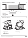
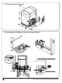
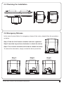
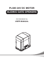
PL500 24V DC MOTOR
SLIDING GATE OPENERS
FOR RESIDENTIAL
USER MANUAL
INDEX
1. Warnings
P.2
2. Installation
P.3
2.1 Standard Installation Demonstartion
P.3
2.2 Description of Device
P.3
2.3 Dimension of Device
P.4
2.4 Installation of Gear Motor And Gear Rack
P.4
2.5 Checking for Installation
P.5
2.6 Emergency Release
P.5
3. Setup And Function Setting
P.6
3.1 Wire Connection
P.6
3.2 Transmitter Memorization
P.7
3.3 System Learning and LED Display
P.7
3.4 Programmable Function Settings
P.8
3.5 Testing and Checking
P.9
3.6 SW2/SW6 Setting
4. Technical Characteriestics
P.10
P.10
4.1 Tenical Data Sheet of Series
P.10
4.2 PH-1 Photocell Data Sheet
P.11
4.3 PR-1 Transmitter Data Sheet
P.11
4.4 PF-1 Flashing Light Data Sheet
P.11
4.5 PRB-1 External Receiver Box Data Sheet
P.11
5. Additional Information
P.12
5.1 Wire Connection Of PH-1 Photocell (Safety Beam)
P.12
5.2 Wire Connection And Setting Of PRB-1 External Reciever Box
P.13
INSTRUCTIONS PL500 SLIDING GATE OPENER USER MANUAL
1
1) Warnings
Please read this instruction manual carefully before the
installation of gate-automated system.
Do not make any modifications to any components except
that it is mentioned in this manual.
This manual is exclusively for qualified installation
personnel. Powertech Electronics Inc. is not responsible for
improper installation and failure to comply with local
electrical and building regulations.
Do not try to manually open or close the gates before you
release the gear motor.
Keep all the components of PL500 system and this manual
for further consultation.
In this manual, please pay extra attention to the contents
marked by the symbol:
If there is a failure that cannot be solved and is not
mentioned in this manual, please contact qualified
installation personnel.
Do not use the gate-automated system before all the
procedures and instructions have been carried out and
thoroughly read.
Test the gate-automated system weekly and have
qualified installation personnel to check and maintain the
system at least every 6-month.
Be aware of the hazards that may exist in the procedures
of installation and operation of the gate-automated
system. Besides, the installation must be carried out in
conformity with local standards and regulations.
Install warning signs (if necessary) on the both sides of
the gate to warn the people in the area of potential
hazards.
If the system is correctly installed and used following all
the standards and regulations, it will ensure a high degree
of safety.
Make sure that the gates works properly before installing
the gate-automated system and confirm the gates are
appropriate for the application.
Do not let children operate
gate-automated system.
or
play
with
the
Do not cross the path of the gate-automated system when
operating.
Please keep all the control devices and any other pulse
generator away from children to avoid the gate-automated
system being activated accidentally.
2
INSTRUCTIONS PL500 SLIDING GATE OPENER USER MANUAL
2. Installation:
2.1 Standard Insatllation Demonstaration
4
3
3
1
1. 24Vdc Sliding motor
2. Transmitter
3. safety photo Sensor
4. Flashing light
2
2.2 Description Of Device
g
c
d
f
b
e
a
a. Operation gear
b. Limit switch device
c. 24Vdc motor
d. Back-up batteries
INSTRUCTIONS PL500 SLIDING GATE OPENER USER MANUAL
e. Release device
f. Control panel
g. Terminals of devices
3
2.3 Dimenstion Of Device
2.4 Installation Of Motor Gear And Gear Rack
1~
>25
50
>100
2m
25
4
INSTRUCTIONS PL500 SLIDING GATE OPENER USER MANUAL
2.5 Checking For Installation
SX
DX
NO
OK
2.6 Emergency Release
In the case of power failure for emergency release of the motor, please follow the procedure
as below:
Step1. Push the lid of release chamber and move rightward
Step2. Insert the key and turn clockwise to unlock the device
Step3. Turn counter-clockwise of the bar to release the motor
To restore the automation, simply reverse the above procedure.
Step1.
INSTRUCTIONS PL500 SLIDING GATE OPENER USER MANUAL
Step2.
Step3.
5
3. Setup And Function Setting:
3.1. Wire Connection
8
7
6
5
4
3
2
1
6
PF-1
9
If the Led display is in normal performing refer to “4.2.1”, you can control the gate by either transmitters or the button
on the board: “UP”-clockwise moving, “SET”- stop and “DOWN”- Counterclockwise moving.
5
4
6
9
6
7
3
3
4
PF-1
2
9
1
Ph2
12
13
14
Close
Open
Stop
GND
Pb
Ph+
GND
+13.75
Light
GND
11
3
EXT-
10
4
EXT+
Ph1
1
9
2
8
5
7
3
6
4
5
5
4
6
3
7
2
6
1
11
8
PPB-1, PKS-1: 10
9
9
8
2
1
14
13
12
11
10
9
8
7
6
5
4
3
2
1
6
AC INPUT
5
LED1 Photocells
LED2 Photocells
LED3 RF Learn
4
3
2
1
AC INPUT
ON
OFF
6
INSTRUCTIONS PL500 SLIDING GATE OPENER USER MANUAL
10
6
PPB-1 PKS-1
11
9
AC INPUT
6
3.2 Transmitter Memorizing
Press “RF Learn” button for 2 seconds, and the LED3 is on; then press the transmitter button (A); the LED3 will blink
twice and then be off. The transmitter learning is completed.
A
B
14
13
1
LED1
LED2
LED3
LED 3
2 Sec
1
LED 3
blink twice
2
LED 3 OFF
3
3.3 System Learning And Led Display
14
13
12
11
10
9
8
7
6
5
4
! CAUTION: Before proceeding to system learning, the transmitter memorizing process has to be completed.
LED1
To complete the system learning, follow
LED2the instructions below:
LED3 + “DOWN” for 3 seconds, and the LED display shows “LEA”
Step1: Press “SET”; then press “SET”
LED1
Stop2: Press button (A) on time, the LED display should shows “ARN”
LED2
Step3: The gate will goes to Auto-learning, please wait for the learning process to be completed
LED3
ON
OFF
Press
3 Sec
Push
1
2
3
ON
A
B
OFF
ON
Press
1~3 Sec
OFF
4
LED Display
5
6
Programmable Functions
“N-L”: The Boxer system learning is not done.
“RUN”: The Boxer system is in normal operation
To program, press SET button for 3 seconds, when the LED display change from RUN to F1,
press UP or DOWN to change function settings (F1 to FA). Then press SET to enter the sub
function within each group, press UP or Down to select sub functions and press SET for
confirmation.
“LEA”: Enter learning mode and then wait for learning instructions.
“ARN”: The system learning is in progress.
The Auto-learning process of gate moving:
“Gate open to the end- stop close to the end- stop.”
INSTRUCTIONS PL500 SLIDING GATE OPENER USER MANUAL
7
3
2
3.4 Programmable Function Settings
LED Display
F1
F2
F3
F4
F5
F6
Definition
Function
Value
Description
Options of Gate
F1-0
Clockwise Opening
Opening direction
F1-1
Counterclockwise Opening
Automatic Closing
F2-0
No automatic closing
F2-1
5 seconds
F2-2
15 seconds
F2-3
30 seconds
F2-4
45 seconds
F2-5
60 seconds
F2-6
80 seconds
F2-7
120 seconds
F2-8
180 seconds
The reactions of the
photocells/ safety
edge/ loop detector
when they detecting
obstacles
Motor Speed
Motor Force
Pedestrian Mode
1. The function can adjust the dir
ection of gate opening.
2. The factory setting is "F1-1".
1. This function can cause the gate
to close automatically after the
paused time.
2. The factory setting is "F2-3”:
30secs as the pause time.
F3-1
F3-2
Please refer to page 9,
F3 settings
1. The factory setting is “F3-1”.
F3-3
F4-1
Slow
F4-2
Medium
F4-3
Fast
F4-4
Very Fast
1. The function can adjust the
running speed of motor.
2. The factory setting is "F4-4".
F5-1
Light
Heavy
F5-2
Light
Heavy
F5-3
Light
Heavy
F5-4
Light
Heavy
F5-5
Light
Heavy
F5-6
Light
Heavy
1. The function can adjust the
running force of motor to be
compatible with the gate weight.
2. The factory setting is "F5-4".
3. The motor force value:
F5-1: 2A
F5-6: 7A
F5-2: 3A
F5-7: 8A
F5-3: 4A
F5-8: 10A
F5-4: 5A
F5-9: 13A
F5-7
Light
Heavy
F5-8
Light
Heavy 4. As over current setting
F5-9
Light
Heavy
F6-0
3 seconds
F6-1
6 seconds
F6-2
9 seconds
F6-3
12 seconds
F6-4
15 seconds
F6-5
18 seconds
F7-0
The flashing light blinks
F5-5: 6A
1. The function can adjust the time
of opening partially.
2. The factory setting is "F6-1".
3. Press button B on the remote to
operate the pedestrian mode.
when the gate starts to move.
F7
Pre-flashing
F7-1
The flashing light blinks 3
seconds before the gate
1. The factory setting is "F7-0".
starts to move.
F8
8
F8-0
75%
Deceleration point
F8-1
80%
programming of total
F8-2
85%
travel distance
F8-3
90%
F8-4
95%
F9-1
50% full speed
F9-2
25% full speed
FA-0
No Auto - reverse
FA-1
1 second
FA-2
3 seconds
FA-3
Reverse to the end
F9
Deceleration Speed
FA
Auto - Reverse when
object impacted
1. The factory setting is “F8-0”.
1. The factory setting is “F9-1”.
1. The factory setting is “FA-3”.
INSTRUCTIONS PL500 SLIDING GATE OPENER USER MANUAL
● F3 function settings:
Logic F3-1
Gate Status
Closed
Open
Stop during moving
The reactions of the photocells when detecting obstacles
Photocell 2
Photocell 1
Photocell 1/ Photocell 2
Stop opening
No effect
Stop opening
No effect
Reloads automatic closing time
Stop opening
Reloads automatic closing time
Closing
No effect
Open
Locks and, on release, reverses to open
Opening
Closes the leaf
No effect
Locks and, on release, continues opening
Logic F3-2
The reactions of the safety edge/ photocell when detecting obstacles
Gate Status
Safety Edge
Photocell 1
Closed
Stop opening
No effect
Open
Reloads automatic closing time
Stop during moving
Stop opening/ closing
Reloads automatic closing time
Closing
Reverses to open for 2 seconds
Open
Opening
Reverses to close for 2 seconds
No effect
Logic F3-3
The reactions of the loop detector/ photocell when detecting obstacles
Gate Status
Loop Detector
Photocell 1
Open
No effect
Closed
Open
Reloads automatic closing time
Stop during moving
Open
Reloads automatic closing time
Closing
Open
Open
Opening
Open
No effect
●
The position of safety devices:
Loop Detector
Photocell 1
Photocell 1
or
Photocell 1 / Photocell 2
Safety Edge
Photocell
Photocell 2
3.5 Testing And Checking
Make sure the notices included in 1.1 General safety precaution “WARNINGS” has been carefully observed.
● Release the gearmotor with the proper release key.
● Make sure the gate can be moved manually during opening and closing phases with a force of max.
390N (40 kg approx.)
● Lock the gearmotor.
● Using the Key selector switch, push button device or the radio transmitter, test the opening, closing and
stopping of the gate and make sure that the gate is in the intended direction.
● Check the devices one by one (photocells, flashing light, key selector, etc.) and confirm the control unit
recognizes each device.
INSTRUCTIONS PL500 SLIDING GATE OPENER USER MANUAL
9
C
D
Stop
Ph2
Ph1
3.6 Sw2/sw6 Setting:
SW6
ON
OFF 1
ON
2
3
4
SW2
6
OFF
Device
1 – ON
3 – ON
Ph1
Photocell-1
Ph2
Photocell-2
Stop
4 – ON
5 – ON
6 – ON
Remote
Remote
None
Default
SW2
5
Default
2 – ON
SW6
SW2
ON
OFF
Device
2/4 Channel
Transmitter
2/4 Channel
Transmitter
Description
Remark
Switch to ON if Ph1 is not connected; Otherwise,
1 & 2 must switch to ON,
switch to OFF if Ph1 is connected
if Ph1 & Ph2 are not
Switch to ON if Ph2 is not connected; Otherwise,
connected to any devices
switch to OFF if Ph2 is connected
Switch to ON if “Stop (12)” is not connected; Otherwise,
switch to OFF if “Stop” is connected to any device
Setting with SW2
Setting with SW2
No function
Description (coordinate with remote)
ON, Button B is pedestrian mode
If connected with external device (EXT+/EXT-; 1/2),
SW6 4-ON; Button C on the remote can operation the device
If connected with external device (EXT+/EXT-; 1/2),
SW6 5-ON; Button D on the remote can operation the device
OFF,Button B can operation the external device
(EXT+/EXT-; 1/2)
OFF,SW6 4-ON; Button C is pedestrian mode;
Button D no function
OFF,SW6 5-ON; Button D is pedestrian mode;
Button C no function
Remark
With external device:
SW6 4 - ON/OFF >
Button C - ON/OFF;
SW6 5 - ON/OFF >
Button D - ON/OFF;
If using a 2-channel
remote and require the
Button B to operation
the external device,
switch the SW2 to OFF
4. Technical Characteristics:
4.1 Techanical Data Sheet Of Series
Motor
Gear type
Peak thrust
Nominal thrust
Engine RPM
Absorbed Power
Power supply
Nominal input power
Maximum gate weight
Maximum gate length
Maximum operating current
Operating Temperature
Dimension LxWxH mm.
Weight
Speed
10
PL500
Worm Gear
5500N
5000N
3800 RPM
60W
24 Vdc
3A
500kg
6 Meters
5.5A for Maximum 10 secs
-20oC~+50oC
250 X 170 X 265
8 kg
21.9 cm / sec
INSTRUCTIONS PL500 SLIDING GATE OPENER USER MANUAL
4.2 PH-1 Photocell Data Sheet
Detection type
Operating distance
Response time
Input voltage
Operating Temperature
Protection class
Dimension
Through beam
30 meters
100ms
AC/DC 12~24V
-20℃~+60℃
IP66
59mm * 87mm * 38mm
4.3 PR-1 Transmitter Data Sheet
Application
Frequency
Coding
Buttons
Power Supply
Operating Temperature
Dimension
Radio transmitter
433.92Mhz
Rolling code
2, for single-gate or dual-gate operation
3V with one CR2032 button type lithium battery
-20℃~+50℃
71.5mm * 33mm * 14mm
4.4 PF-1 Flashing Light Data Sheet
Application
Installation
Operating Temperature
Dimension
For outdoor use
Wall mounted vertically
-20℃~+50℃
85mm * 60.5mm * 40.5mm
4.5 PRB-1 External Receiver Box Data Sheet
Power Supply
Radio Frequency
Max. remote memorized
Dimensions
Output terminals
12V ~ 24V ac/dc
433.92Mhz
200pcs
106mm* 53mm* 20mm (L*W*H)
Output 1 & Output 2
INSTRUCTIONS PL500 SLIDING GATE OPENER USER MANUAL
11
5. Additional Information:
5.1 PH-1 Photocells
1). Decide the installation position of the photocells. See Figure 3.3.6 (1).
2). Unscrew the screws and secure the photocells on the post A, B or C. See Figure 3.3.6 (2) and (3).
Figure 3.3.6 (1)
Figure 3.3.6 (2)
Figure 3.3.6 (3)
B
A
C
3). Wiring connection:
TX: Connect terminals 1 and 2 on the transmitter with the terminals GND and 24V on the PC200 PCB.
RX: Connect terminals 1, 2 and 4 on the receiver with the terminals GND, 24V and phot1 on the
PC200 PCB. And use an extra wire to connect terminals 2 and 5 on the receiver as a bridge.
See Figure 3.3.6 (4) Figure 3.3.6 (5) and Figure 3.3.8 (5)
Figure 3.3.6 (5)
Transmitter
Figure 3.3.6 (4)
CA
CC
1
2
NA
NC
C
3
4
5
NA: Normal Open
NC: Normal Close
: DC(+) Input Voltage
: DC(-) Input Voltage
V
E
R
T
O
R
I
Z
V
E
R
T
CA
CC
C: Common
CA: AC(12~24)
CC: DC(12~24)
VERT:Vertical
ORIZ:Horizontal
Receiver
NA NC
1
2
3
4
C
5
O
R
I
Z
Power LED: Green
CA
CC
NA NC
1
2
3
4
C
5
O
R
I
Z
Vertical Adjustment
Horizontal Adjustment
LED:Red(Beam Alignment)
5.2 Wire Connection And Setting Of PRB-1 External Reciever Box
RB1 Receiver Box
12
Orange
-Signal 1
Blue
-GND
Yellow
-Signal 2
Green
-GND
Red
-12V/24V
Black
-GND
Output 1 (Normally Open Relay)
Output 2 (Normally Open Relay)
12V - 24V AC/DC
INSTRUCTIONS PL500 SLIDING GATE OPENER USER MANUAL
1. Situation:
In order to use one 4 channel remote to operate with additional device besides the original gate automation
system. Install a receiver box to connect with the 2nd device (Such as swing/sliding gate opener)
or the 3rd device (Such as garage automation system)
Original gate automation: Using Button A & B (Pedestrian Mode) on the remote to control gate opener
2nd device: Install an external receiver box, connect output 1 to the 2nd device (such as another Boxer
Slider, shown as below) use button C on the same remote to control the 2nd device
3rd device: install an external receiver box, connect the output 2 to the 3rd device (such as garage door),
use the Button D now to operate.
2. Wire Connection:
Orange
-Signal 1
Blue
-GND
Yellow
-Signal 2
Green
-GND
Red
-12V/24V
Black
-GND
9
10
11
Ph+
Pb
GND
a. Orange cable (Signal 1) connect to terminal 10 (Pb) on the control board
b. Blue cable (GND) connect to terminal 11 (GND) on the control board
c. Red cable (12V/24V ac/dc) connect to terminal 9 (Ph+) on the control board
d. Black cable (GND) connect to terminal 11 (GND) on the control board
3. Device Testing & Remote Memorization
a. After connect all necessary cables properly , press
Test Button to exam if the output 1 is working, the
gate opener should operate.
b. If Output 1 is functional, press and hold Learn Button
for 1 second, the LED light should be “ON”
* If the LED does not response, please check the
cable connection again
c. Press and hold Button C on the remote for 1 second
after the LED is “ON”. The remote completed the
memorizing process when LED light turns “OFF”
PRB-1 Receiver
1095 Budapest, Mester utca 34.
Tel.: *218-5542, 215-9771, 215-7550,
216-7017, 216-7018 Fax: 218-5542
Mobil: 30 940-1970, 20 949-2688
1141 Budapest, Fogarasi út 77.
Tel.: *220-7940, 220-7814, 220-7959,
220-8881, 364-3428 Fax: 220-7940
Mobil: 30 531-5454, 30 939-9989
E-mail: [email protected] Web: www.delton.hu
www.kaputnyitunk.hu
INSTRUCTIONS PL500 SLIDING GATE OPENER USER MANUAL
13