1
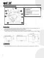
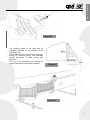
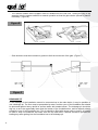
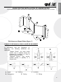
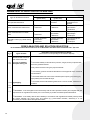
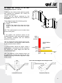
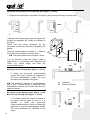
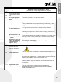
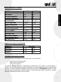
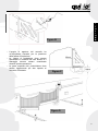
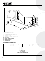
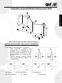
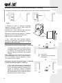
E N G L I S H use and I T A L I A N O ma int e em nc na ma nu te nzio ne anual e so u ’ d manuale SUB UNDERGROUND GEARMOTOR FOR SWING GATES AUTOMAZIONE INTERRATA PER CANCELLI A BATTENTE QK-SUB24 – QK-SUB220 C O N T E N T S TECHNICAL FEATURES 21 3 FOUNDATION BOX DIMENSION 21 3 PRE-INSTALLATION CONTROL 3 21 MATERIALS FOR INSTALLATION 4 22 INSTALLATION 4 22 DRAINAGE PIT 6 24 MOUNTING THE MECHANICAL LIMIT SWICTHES (OPTIONAL QK-FCKIT) 7 GENERAL ADVICE 8 26 USE 8 26 MAINTENANCE 9 27 TYPICAL SYSTEM 10 28 ELECTRICAL CABLES’ CROSS SECTION 10 28 GUIDE FOR INSTALLING SWING GATES 11 29 MAINTENANCE RECORD BOOK 17 35 DECLARATION OF COMPLIANCE (1) 19 37 DECLARATION OF COMPLIANCE (2) 20 38 E N G L I S H E N G L I S H TECHNICAL FEATURES E N G L I S H TECHNICAL DATA QK-SUB220 QK-SUB24 MOTOR’S FEEDING 230Vac 24Vdc FREQUENCY 50Hz - ABSORBED POWER 350W 50W ABSORBED CURRENT 2,1A 5,2A OPERATING TEMPERATURE -30 / +70 °C -30 / +70 °C MOTOR SPEED 1400rpm 1500rpm OPENING TIME 16” 16” NOMINAL THRUST 380N 300N PROTECTION DEGREE IP67 IP67 WORKING CYCLE 30% max 30% max MOTOR’S WEIGHT 10 Kg 9,5 Kg CAPACITOR 12,5µf NO THERMAL PROTECTION 150°C NO PERMANENT LUBRICATION YES YES MAX. LEAF LENGTH 3m 3m MAX. LEAF WEIGHT 400 Kg 400 Kg FOUNDATION BOX DIMENSION DIMENSION QK-CFSUB LENGTH 375mm 375mm WIDTH 320mm 320mm HEIGHT 225mm 225mm PRE-INSTALLATION CONTROL Before installing the automation, you must check: - size and weight of gate; wind and temperature factor; operating frequency; Borinato F.lli Snc is liable only for products it manufactures and commercializes. Once automated, the gate becomes a machine and is therefore subjected to the rules of the “ Machinery Directive”. It is on the installer to verify its security. WARNING: Borinato F.lli Snc is not liable for any damages to people, animals or things due to unauthorized modifications, alterations or betterments on its products by third parties. MATERIALS FOR INSTALLATION 1 – Foundation box; 2 – Gearmotor; 3 – Motor lever; 4 – Mechanical limit switch for closing (optional); 5 – Connecting lever; 6 – Unlocking lever; 7 – Support bracket; 8 – Mechanical limit switch for opening (optional); 9 – Sphere; INSTALLATION − The pivot point of the gate can be found on the foundation box, that is on the unlocking lever, on which the sphere will be inserted and the leaf will be welded; − QK-SUB24 and QK-SUB220 operators can open gates up to a 110° angle; − To open the gate up to a 180° angle please request the apposite optional accessory (QK-KIT180). Figure A − Once the foundation box has been settled in place, the gate can be mounted above. (Figure D) E N G L I S H E N G L I S H E N G L I S H Figure B − The opening angle of the gate has an important influence on the position of the foundation box; − The foundation box must be set in concrete. Piping for electrical wiring and drainage should be borne in mind during this operation; − The top of the foundation box should be slightly higher than surrounding concrete. Figure C Figure D − The manual release device support must be welded onto the leaf now. Turning the key in the apposite hole the system switches to manual operation so that the gate can be opened by hand if necessary. (Figure E) Figure E E N G L I S H − Gate knockers must be mounted on ground to limit the movement of the gate. (Figure F) Figure F DRAINAGE PIT If the drainage of the installation cannot be connected up to the main drains, it may be possible to use a drainage pit. The floor must be permeable by water, and the cover of the foundation box should be protected against heavy rainfall or surface water with sealant silicon. The drainage pit should be dug out so as to be appreciably lower than the bottom of the foundation box, and its capacity should exceed the one of the foundation box. The pit should be filled with course ruble or gravel, an should be tiled to keep out sediment and water from the top and sides. Facilities should be provided for leading any water getting into the foundation box to the drainage pit. E N G L I S H E Figure G N G L Cable function: I S COMMON H L1 L2 GROUND = BLUE = BLACK = BROWN = YELLOW / GREEN Do not forget to check the earth system. The condenser has to be connected between L1 and L2 (BLACK and BROWN) and has to be protected against water. MOUNTING THE MECHANICAL LIMIT SWITCHES (QK-FCKIT) - MOUNTING THE MECHANICAL LIMIT SWITCH FOR CLOSING: Proceed as displayed within FIGURE H paying attention not to screw the limit switch completely up so to allow a little movement; Figure H - MOUNTING THE MECHANICAL LIMIT SWITCH FOR OPENING: Proceed as displayed within FIGURE I paying attention not to screw the limit switch completely up so to allow a little movement; Figure I . ADJUSTING THE MECHANICAL LIMIT SWITCHES Mechanical limit switches have to be adjusted once the motors have been connected to the control unit and located in the final position. Screw the apposite screws when the leaf is on position. GENERAL ADVICE Install a gate’s safety system that complies with current regulations. Choose short routes for cables and keep power cables separate from control ones. Install the control card in a waterproof box. Please refer to current regulations when setting the gear motor’s maximum torque. We advice you to install an outdoor switch, in compliance with European standards on the issue of safety, to turn the electricity off when servicing the gate. Check that each single installed device is efficient and effective. Affix easily readable signs warning about the presence of a motorized gate. USE It is absolutely forbidden to use the device for any other purposes. The installed electronic unit (which must have built-in electric friction), allows to select the following functions: automatic: one control impulse will open or close the gate; semi-automatic: one control impulse will open or close the gate. In case of blackout, act on the manual unlocking device and move manually the gate. Remember that this is an automatic device powered by electricity, consequently use with care. In particular, remember: - not to touch the device with wet hands and/or wet or bare feet; to turn off electricity before opening the control box and/or actuator; not to pull the lead to pull the plug out; to put the gate in movement only when it is completely visible; to keep out of the gate’s range of action if it is moving. Wait until it has stopped; not to let children or animals play near the gate; not to let children use the remote control or other operating devices; to carry out routine maintenance; in case of failure, to turn off electricity and operate the gate manually only if it is possible and safe. Refrain from touching the gate and call an authorized technician. E N G L I S H E N G L I S H MAINTENANCE Actuators need very little maintenance; however their function depends also on the gate conditions, hence here are operations to be done to keep the gate efficient at all times. Warning: no one but the maintenance man, who must be a specialized technician, must be able to control the automatic gate while it is being serviced. For this reason please turn off electricity, avoiding also electric shocks hazard. If on the contrary electricity must be on for certain checks, remember to check or disable any control device (remote controls, push button panels etc.) except the one used by the service man. E N G L I S H Routine maintenance Each of the following operations must be done when needed and in all cases at least every 6 months: 1) Mechanical maintenance - Lubricate (with oilier) the hinges on which the gate swings; - check the good conditions of brackets and motor’s hinges; - do an unlocking operation to be sure the mechanism is always efficient. 2) Electrical maintenance - Check the proper working of the safety devices; - check the electronic friction’s efficacy; - check the earth system’s (differential’s) efficacy. Try the differential switcher once a month by pushing the special test button on the switcher. TYPICAL SYSTEM E N G L I S H MAIN COMPONENTS 1 – UNDERGROUND GEARMOTOR 2 – PHOTOCELLS 3 – PHOTOCELLS ON LITTLE COLUMNS 4 – GATE KNOCKERS 5 – KEY SELECTOR 6 – FLASHING LIGHT 7 – CONTROL UNIT 10 ELECTRICAL CABLES’ CROSS SECTION 24V (QK-SUB24) A = 2x1.5 mm2 B = 2x1.5 mm2 220V (QK-SUB220) A = 4x1.5 mm2 B = 4x1.5 mm2 C = 4x0.5 mm2 D = 2x0.5 mm2 E = 2x0.5 mm2 F = 4x0.5 mm2 G = 3x0.5 mm2 H = 3x1 mm2 I = 3x1.5 (supply line) E N G L I S H GUIDE FOR THE INSTALLATION OF HINGED GATES IN ACCORDANCE WITH REGULATION 98/37/CE ON MACHINERY AND WITH REGULATION EN 12453 – EN 12445 E N G L I S H Risk Areas on Hinged Gates (figure 1) LEGEND OF MECHANICAL RISKS CAUSED BY MOVEMENT In accordance with the Regulation on Machinery, the following definitions are applicable: − “Danger Zones:” any area inside and/or near a machine where the presence of a person is a risk to his/her health and safety. − “Exposed Person:” any person located entirely or partially in a danger zone. E C A. Impact D. Conveyance A D B. Crushing E. Cutting B F C. Insulation F. Slicing 11 MINIMUM LEVEL OF PROTECTION FOR THE MAIN EDGE Type of Activation Controls Informed Users (private area) Mode of Use Informed Users (public area) □ Button command □ Turnkey button Pulse command with visible doors □ Power limitation □ Detectors □ Power limitation □ Detectors Pulse command with non-visible doors □ Power limitation □ Detectors □ Power and photo Automatic control (e.g. timed closing control) □ Power and photocell limitation □ Detectors □ Power and photo- Man-operated Command command cell limitation □ Detectors cell limitation □ Detectors Uninformed Users The man-operated command is not allowed □ Power and photo cell limitation □ Detectors □ Power and photo cell limitation □ Detectors □ Power and photocell limitation □ Detectors RISKS ANALYSIS AND SOLUTION SELECTION IN ACCORDANCE WITH REGULATION 98/37/CE ON MACHINERY AND WITH REGULATIONS EN 12453 – EN 12445 MD Annex 1 Evaluation Criteria and Solutions to Adopt (Check the box corresponding to the solution adopted) Types of Risks Structural and wear-andtear mechanical risks 1.3.1 1.3.2 [1] Loss of stability and parts falling off □ Check the stability of this structure (columns, hinges, doors) compared with the motor-generated stress. Firmly fasten the motor using the proper materials. □ If necessary, perform structural calculations in the appendix of the Technical Documentation. □ Check that the thrust of the doors is limited (when opening and closing) by appropriately firm mechanical stops. □ Check that eventual thresholds greater than 5 mm are visible, marked and 1.5.15 [2] Slipping 1.3.7 Mechanical risks caused by the movement of the door (see references in figure 1) modeled. 1.3.8 1.4 □ WARNING - If the door/gate is used exclusively with the man-operated controls (and complies with the requirements of regulation EN 12453) it is not necessary to protect the hazard points listed below. □ WARNING - If the safety devices are installed (in accordance with regulation EN 23978) which prohibit all contact between the moving door and people (e.g. photo-electric barriers, detectors), it is not necessary to measure the actual operative stress. 12 E N G L I S H E N G L I S H [3] Impact and Crushing on the Main Closing Edge (figure 1, risk A) □ Measure the closing stress (with the proper tool required by regulation EN 12445) as indicated in the figure. Check that the values measured by the instrument are less than the ones indicated in the graphic. 300 Take measurements at the following points: L = 50, 300, and 500mm; H = 50mm, at half of the height of the door and at the height of the door minus 300 mm (max 2500). = E N G L I S N.B. The measurements must be taken three H times at each point. 50 In the graphic, the maximum values of the dynamic operative, static and residual stresses are indicated compared with the different positions of the door. = Stress 1400 N L>500 mm N.B. As regards the measurement points L=50, 300, and 500mm, the maximum value allowed by the dynamic stress is 400 N. □ If the stresses' values are higher, install a safety device in accordance with the regulation EN 12978 (e.g. safety edge) and take the measurements again. Dynamic IMPACT Stress 400 N L=50÷500 mm Static CRUSHING Stress 150 N 25 N 0,75 s 500 time 5s N.B. The reduction of the dynamic stress can be obtained for example by reducing the door speed or by using a sensitive edge with a high elastic shear. Door with Overlapped and Delayed Close 300 50 F 50 300 F Protective Device 500 Protective Device 13 [4] Impact and Crushing in the Opening Area (figure 1, risk B) ≥500 □ Observe the safe distance indicated in the figure (at the most protruding part of the door). Motor ≥200 ≥500 ≥500 E N G L I S H or □ Measure the closing stress (with the proper tool required by regulation EN 12445) as indicated in the figure. Check that the values measured by the instrument are less than the ones indicated by the graphic. Take the measurements at height H = 1000mm (or at the most protruding part of the door). N.B. The measurement must be taken 3 times. 500 □ If the stresses' values are higher, install a [5] Impact in the Closing Area (figure 1, risk C) A 300 B A 200 safety device in accordance with regulation EN 12978 (e.g. safety edge) and take the measurements again. □ Install two photo-cells (recommended height: 500 mm) to detect the presence of the test parallelepiped (height 700 mm) positioned as indicated in the figure. N.B. The sample for detection is a parallelepiped (700 x 300 x 200mm) having 3 sides with clear and reflective surfaces and 3 sides with dark and opaque surfaces. A. B. Photocell; Detection Sample A [6] Impact in the Opening Area (figure 1, risk B) and in the Closing Area (figure 1, risk C) □ To further reduce the chance of impact in 14 B 200 the gate's moving areas (A and C), it is possible to install two photo-cells (recommended height: 500 mm) to detect the presence of the test parallelepiped (height 700 mm) positioned as indicated in the figure. 300 A A MD Annex 1 1.3.7 1.3.8 1.4 E N G L I S H E N G L I S H Evaluation Criteria and Solutions to Adopt (Check the box corresponding to the solution adopted) Types of Risks Mechanical risks caused by the movement of the door [7] Crushed hands on the hinge edge (figure 1, risk D) □ Check for the presence of a free space ≥ 25mm. or □ Apply protectors that prevent fingers from being introduced (e.g. rubber edging). [8] Placing the feet on the lower edge (figure 1, risk E) □ The gap between the door and the pavement must prevent the introduction of feet. N.B. If the gap changes due to the slope of the floor, apply protectors (e.g. rubber edging). [9] Placing hands in the activation group (figure 1, risk F) □ if the distances between the activation group and the door change, check [10] Placing, slicing and cutting due to shaping of the moving door (figure 1, risk G) □ Remove or protect eventual sharp edges, protruding parts, etc... (e.g. for the gap ≥ 25mm or apply protectors (e.g. coverings or rubber edging). with coverings or rubber edging). Electrical and electromagnetic compatibility risks 1.5.1 1.5.2 [11] Lost Contacts Electricity Detection □ Use CE components and materials in accordance with the Regulation on Low Tension (73/23/CEE). □ Perform the electrical connections, the network connection, the ground connections and relative checks, in compliance with the local norms and as indicated in the installation manual of the activation group. N.B. If the electrical power line is already connected (through socket and also through cable box), compliance declarations with Italian Law 46/90 are not compulsory. 1.5.10 1.5.11 [12] Risks of electromagnetic compatibility □ Use CE components in compliance with the EMC Directive (89/336/CCE). Perform the installation as indicated in the installation manual of the activation group. 15 MD annexed 1 Evaluation Criteria and Solutions to Adopt (Check the box corresponding to the solution adopted) Types of Risks Safety and Information Integration Principles 1.7.1 [13] Notification Means □ Install the blinker in a visible position to signal the movement of the door. □ To regulate traffic vehicles, install traffic lights. □ It is also possible to apply reflectors on the doors. 1.7.2 [14] Signs □ Apply all necessary signs and warnings to draw attention to possible unprotected residual risks and to warn about eventual, foreseeable, uses that are non-compliant. 1.7.3 [15] Labeling □ Apply the CE label or tag containing at least that indicated in the figure: Automatic Gate Producer (name – address): Gate Type: Identification Number: Year of Construction: 1.7.4 [16] Instructions for Use □ Deliver the instructions for use, safety warnings and CE Compliance Declaration to the user. 1.6.1 [17] Maintenance □ A maintenance plan must be compiled and carried out. Check the proper safety operations at least every 6 months. □ Register eventual events in the Maintenance Record Book in accordance with regulation EN 12635. 1.1.2 16 [18] Residual, unprotected risks □ Inform the user in writing (for example, in the instructions for use) of possible residual, unprotected risks and foreseeable improper use. E N G L I S H E N G L I S H Technical Assistance: MAINTENANCE RECORD BOOK (Name, address, telephone) This Maintenance Record Book contains technical information as well as a list of installations, maintenance and repairs performed and must be available for possible inspections by authorized bodies. TECHNICAL DATA AND INSTALLATION OF THE MOTORIZED DOOR/GATE Customer: E N G L I S H _____________________________________________________________ Name, Address, Contact Person Order Number: E N G L I S H _____________________________________________________________ Customer Order Number and Date Model and Description: _____________________________________________________________ Type of Door/Gate Size and Weight: _____________________________________________________________ Size of the Passage, Size and Weight of the Door Serial Number: _____________________________________________________________ Unique Identification Number of the Door/Gate Location: _____________________________________________________________ Installation Address LIST OF COMPONENTS INSTALLED Motor/Activation Group: _____________________________________________________________ Model, Type, Serial Number Electrical Panel: _____________________________________________________________ Model, Type, Serial Number Photo-cells: _____________________________________________________________ Model, Type, Serial Number Safety Devices: _____________________________________________________________ Model, Type, Serial Number Control Devices: _____________________________________________________________ Model, Type, Serial Number Radio Devices: _____________________________________________________________ Model, Type, Serial Number Blinker: _____________________________________________________________ Model, Type, Serial Number Other: _____________________________________________________________ Model, Type, Serial Number 17 LIST OF RESIDUAL RISKS AND IMPROPER, FORESEEABLE USE Notification through signs posted on the product’s danger points and/or through written notices to deliver to and explain to the user or the person in charge about the existing risks and the improper, foreseeable use. _____________________________________________________________________________________________ _____________________________________________________________________________________________ _____________________________________________________________________________________________ MAINTENANCE RECORD BOOK Description of the Intervention (Check the box corresponding to the intervention carried out. Describe possible residual risks and/or improper, foreseeable use) □ Installation □ Start-up □ Adjustments □ Maintenance □ Repairs □ Changes Date: ______________Signature of the Technician: ________________Signature of the Customer: ___________ Description of the Intervention (Check the box corresponding to the intervention carried out. Describe possible residual risks and/or improper, foreseeable use) □ Installation □ Start-up □ Adjustments □ Maintenance □ Repairs □ Changes Date: ______________Signature of the Technician: ________________Signature of the Customer: ___________ Description of the Intervention (Check the box corresponding to the intervention carried out. Describe possible residual risks and/or improper, foreseeable use) □ Installation □ Start-up □ Adjustments □ Maintenance □ Repairs □ Changes Date: ______________Signature of the Technician: ________________Signature of the Customer: ___________ 18 DECLARATION OF COMPLIANCE (by the installer) The undersigned: Address: in charge of the set-up, declares that the product: Gate type: Location: are in compliance with the essential safety requirements of the regulations: Regulation 89/392CE on Machinery and its subsequent amendments; EMC Regulation 89/336/CE (Legislative Decree 615/96); BT Regulation 73/23/CE e 93/68/CE (Legislative Decree 626/96); CE Machinery Directive 98/37 and directive 93/68/CE-72/23/CE-92/31/CE; and also declares that the related and/or specific national technical regulations have been followed: Notes: EN 12453/EN 12445 on Industrial, Commercial and Residential Gates and Doors – Safe Use of Motorized Doors – Requirements and Classification – Test Methods; EN 12604/ EN 12605 on Industrial, Commercial and Residential Gates and Doors – Mechanical Aspects – Requirements and Classification – Test Methods; CEI 64/8 Electrical Systems Using Nominal Tension Not Higher Than 1000V a.c. and 1500 V d.c.; EN 13241-1 (Industrial, commercial and garage doors and gates), conformity evaluation (6.3). SEAL AND SIGNATURE Place and date: ………………………………… 20 E N G L I S H 21 manuale I T A L I A N O d’u so e nu ma ione tenz SUB AUTOMAZIONE INTERRATA PER CANCELLI A BATTENTE QK-SUB24 – QK-SUB220 I T A L I A N O I T A L I A N O S O M M A R I O S O M M A R I O CARATTERISTICHE TECNICHE 2 DIMENSIONI MOTORIDUTTORE CARATTERISTICHE TECNICHE 2 32 CONTROLLO PRE-INSTALLAZIONE DIMENSIONI CASSA DI FONDAZIONE 2 32 MATERIALI PER L’INSTALLAZIONE 3 32 INSTALLAZIONE 3 43 SCHEMA CENTRALINA 5 SICUREZZA 6 FUNZIONI DEI DIP 6 MEMORIZZAZIONE DEI TELECOMANDI 6 CONTROLLO PRE-INSTALLAZIONE MATERIALI PER L’INSTALLAZIONE INSTALLAZIONE POZZO DI DRENAGGIO MONTAGGIO DEI FINECORSA MECCANICI (OPTIONAL QK-FCKIT) RACCOMANDAZIONI DI CARATTERE GENERALE RACCOMANDAZIONI DI CARATTERE GENERALE USO USO 7 7 43 65 76 87 87 MANUTENZIONE 7 98 IMPIANTO TIPO IMPIANTO TIPO 8 109 SEZIONE ELETTRICIDI PORTE SEZIONALI GUIDADEI PERCAVI L’INSTALLAZIONE 9 109 GUIDA PER L’INSTALLAZIONE REGISTRO DI MANUTENZIONE DEI CANCELLI A BATTENTE 10 1611 REGISTRO DI MANUTENZIONE DICHIARAZIONE DI CONFORMITÀ (1) 16 1817 DICHIARAZIONEDIDICONFORMITA’ CONFORMITÀ (2) (1) DICHIARAZIONE 1919 18 DICHIARAZIONE DI CONFORMITA’ (2) 20 19 MANUTENZIONE 1 CARATTERISTICHE TECNICHE DATI TECNICI QK-SUB220 QK-SUB24 ALIMENTAZIONE MOTORE 230Vac 24Vdc FREQUENZA 50Hz 50Hz POTENZA ASSORBITA 350W 50W CORRENTE ASSORBITA TEMPERATURA DI FUNZIONAMENTO 2,1° 5,2A -30 / +70 °C -30 / +70 °C VELOCITÀ MOTORE 1400rpm 1500rpm TEMPO DI APERTURA 16” 16” COPPIA 380N 300N GRADO DI PROTEZIONE IP67 IP67 CICLO DI LAVORO 30% max 30% max PESO MOTORE 10 Kg 9,5 Kg CONDENSATORE 12,5µf NO PROTEZIONE TERMICA 150°C NO LUNGHEZZA MAX ANTA 3m 3m PESO MAX ANTA 400 Kg 400 Kg I T A L II A T N OA L I A N O DIMENSIONI CASSA DI FONDAZIONE DIMENSIONI QK-CFSUB LUNGHEZZA 375mm 375mm LARGHEZZA 320mm 320mm ALTEZZA 225mm 225mm CONTROLLO PRE-INSTALLAZIONE Prima di procedere all’installazione dell’automazione occorre verificare: - dimensione e peso del cancello; fattore vento / temperatura; frequenza d’esercizio; Si ricorda che Borinato F.lli Snc è responsabile solo degli articoli che produce e commercializza. II cancello, una volta automatizzato, diventa un macchinario ed è quindi soggetto alle norme della Direttiva Macchine. E' quindi compito dell'installatore verificarne la sicurezza. ATTENZIONE: Borinato F.lli Snc non risponde di eventuali danni a persone, animali o cose derivanti da modifiche, alterazioni o migliorie apportate arbitrariamente da terzi ai suoi prodotti. I MATERIALI PER L’INSTALLAZIONE T A L I A N O 1 – Cassa di fondazione; 2 – Gruppo motoriduttore; 3 – Leva motoriduttore; 4 – Finecorsa meccanico chiusura; 5 – Biella; 6 – Chiave sblocco manuale; 7 – Leva di sblocco; 8 – Finecorsa meccanico apertura; 9 – Sfera. INSTALLAZIONE − Il centro di rotazione dell’anta si trova sulla cassa di fondazione, cioè nel supporto dello sblocco, sul quale verrà inserita la sfera e successivamente saldata l’anta; − Gli automatismi interrati tipo QK-SUB24 e QK-SUB220 aprono le ante fino ad un angolo pari a 110°. − Per aperture fino a 180° richiedere l’apposito acc essorio opzionale. Figura A − Dopo aver collocato in posizione corretta la cassa di fondazione, il cancello può essere montato sopra di essa. (Figura D) I T A L I A N O I T A L I I AT NA O L I A N O Figura B − L’angolo di apertura del cancello ha un’importanza rilevante per la posizione della cassa di fondazione. − La cassa di fondazione deve essere cementata. Le tubature dei cavi elettrici e il drenaggio devono essere considerate durante questa operazione. − La parte superiore del motoriduttore deve essere leggermente più alta rispetto al cemento circostante. Figura C Figura D − Il supporto per lo sblocco manuale deve essere saldato ora all’anta. Inserendo la chiave di sblocco nel foro apposito, l’anta può essere sbloccata ed aperta manualmente. (Figura E) Figura E − I battenti devono essere installati sul pavimento per limitare il movimento del cancello. (Figura F) Figura F POZZO DI DRENAGGIO Se non fosse possibile collegare il pozzo di drenaggio agli scarichi principali, si potrebbe usare una fossa di scarico. Il fondo d’essa deve essere permeabile all’acqua. La copertura dell’alloggiamento del motore deve essere protetta contro la pioggia intensa o l’acqua di superficie con del silicone sigillante. La fossa di scarico dovrebbe essere scavata in modo tale da essere sensibilmente più bassa del fondo dell’alloggiamento del motore e la sua capacità deve superare quella dell’alloggiamento del motore. La fossa deve essere colmata con ghiaia e piastrellata per tenere lontani sedimenti e l’acqua dalle parti superiori e dai fianchi. Devono essere previsti dei mezzi per scaricare in questa fossa di drenaggio eventuale acqua che penetri nell’alloggiamento del motore. Figura G I T A L II AT NA O L I A N O La codificazione dei fili del motoriduttore è la seguente: COMUNE = L1 = L2 = TERRA = BLU NERO MARRONE GIALLO / VERDE Non dimenticare di controllare l’impianto di messa a terra. Il condensatore viene collegato tra L1 e L2 (fili NERO e MARRONE) e deve essere protetto contro l’acqua. MONTAGGIO DEI FINECORSA MECCANICI (QK-FCKIT) - MONTAGGIO DELL’ARRESTO DI FINE CORSA PORTA CHIUSA:Procedere come illustrato in FIGURA I facendo attenzione a non serrare completamente le viti in modo che il gruppo di finecorsa possa muoversi; Figura H - MONTAGGIO DELL’ARRESTO DI FINECORSA PORTA APERTA: Procedere come illustrato in FIGURA I facendo attenzione a non serrare completamente le viti in modo che il gruppo di finecorsa possa muoversi; I T A L I A N O Figura I REGOLAZIONE FINECORSA MECCANICI I finecorsa meccanici vengono regolati soltanto con il motoriduttore collegato alla centrale. La regolazione avviene mediante la vite di fermo che sarà fissata nel punto voluto. RACCOMANDAZIONI DI CARATTERE GENERALE Integrare la sicurezza del cancello conformemente alla normativa vigente. Scegliere percorsi brevi per i cavi e tenere separati i cavi di potenza dai cavi di comando. Installare la scheda di comando in una scatola a tenuta stagna. Per la messa a punto della coppia massima del motoriduttore, attenersi alle normative in vigore. In accordo con la normativa europea in materia di sicurezza si consiglia di inserire un interruttore esterno per poter togliere l’alimentazione in caso di manutenzione del cancello. Verificare che ogni singolo dispositivo installato sia efficiente ed efficace. Affiggere cartelli facilmente leggibili che informino della presenza del cancello motorizzato. USO Si fa espresso divieto di utilizzare l'apparecchio per scopi diversi. La centralina elettronica installata (che deve avere la frizione elettrica incorporata) consente di selezionare il funzionamento: automatico: un impulso di comando esegue l'apertura e la chiusura del cancello; semiautomatico: un impulso di comando esegue l'apertura o la chiusura del cancello. In caso di mancanza di energia elettrica, agire sul dispositivo di sblocco manuale e muovere il cancello manualmente. Si ricorda che siamo in presenza di un dispositivo automatico e alimentato a corrente, perciò da usare con precauzione. In particolare, si esorta a: non toccare l'apparecchio con mani bagnate e/o piedi bagnati o nudi; togliere la corrente prima di aprire la scatola comandi e/o il motoriduttore; non tirare il cavo di alimentazione per staccare la presa di corrente; mettere in movimento il cancello solo quando è completamente visibile; tenersi fuori dal raggio di azione del cancello se questo è in movimento: aspettare fino a che non sia fermo; non lasciare che bambini o animali giochino in prossimità del cancello; non lasciare che bambini usino il telecomando o altri dispositivi di azionamento; effettuare una manutenzione periodica; - in caso di guasto, togliere l'alimentazione e gestire il cancello manualmente solo se possibile e sicuro. Astenersi da ogni intervento e chiamare un tecnico autorizzato. I T A L I A NI O MANUTENZIONE Gli attuatori necessitano di poca manutenzione; tuttavia il loro buon funzionamento dipende anche dallo stato del cancello, perciò descriveremo brevemente anche le operazioni da fare per avere un cancello sempre efficiente. Attenzione: nessuna persona ad eccezione del manutentore, che deve essere un tecnico specializzato, deve poter comandare il cancello automatico durante la manutenzione. Si raccomanda perciò di togliere l'alimentazione di rete, evitando così anche il pericolo di shock elettrici. Se invece l'alimentazione dovesse essere presente per talune verifiche, si raccomanda di controllare o disabilitare ogni dispositivo di comando (telecomandi, pulsantiere, ecc.) ad eccezione del dispositivo usato dal manutentore. T A L I A N O Manutenzione ordinaria Ciascuna delle seguenti operazioni deve essere fatta quando se ne avverte la necessità e comunque ogni 6 mesi: 1) Manutenzione meccanica - Lubrificare (con oliatore) i cardini su cui il cancello gira; - controllare il buono stato delle staffe e i perni del motore; - effettuare una manovra di sblocco per assicurarsi che il meccanismo sia sempre efficiente. 2) Manutenzione elettrica - Controllare il buono stato dei dispositivi di sicurezza; - controllare l’efficacia della frizione elettronica; - controllare l’efficacia dell’impianto di terra (differenziale). Provare l’interruttore differenziale una volta al mese premendo l’apposito pulsante di test sull’interruttore. I T A L I A N O IMPIANTO TIPO COMPONENTI PRINCIPALI 1 – MOTORIDUTTORI INTERRATI 2 – FOTOCELLULE 3 – FOTOCELLULE SU COLONNINE 4 – BATTENTI 5 – SELETTORE A CHIAVE 6 – LAMPEGGIANTE 7 – CENTRALINA SEZIONE DEI CAVI ELETTRICI VERSIONE A 24V (QK-SUB24) A = 2x1.5 mm2 B = 2x1.5 mm2 VERSIONE A 220V (QK-SUB220) A = 4x1.5 mm2 B = 4x1.5 mm2 C = 4x0.5 mm2 D = 2x0.5 mm2 E = 2x0.5 mm2 F = 4x0.5 mm2 G = 3x0.5 mm2 H = 3x1 mm2 I = 3x1.5 (linea alimentazione) 10 GUIDA PER L’ISTALLAZIONE DEI CANCELLI A BATTENTE I T A L I I A T N A O IN CONFORMITÀ ALLA DIRETTIVA MACCHINE 98/37/CE E ALLE NORME EN 12453 – EN 12445 L I A N O Zone di rischio del cancello a battente (figura 1) LEGENDA DEI RISCHI MECCANICI DOVUTI AL MOVIMENTO Ai sensi della Direttiva Macchine, si intende per: − “Zone pericolose”, qualsiasi zona all’interno e/o in prossimità di una macchina in cui la presenza di una persona esposta costituisca un rischio per la sicurezza e la salute di detta persona. − “Persona esposta”, qualsiasi persona che si trovi interamente o in parte in una zona pericolosa. C A. Impatto D. Convogliamento A E D B. Schiacciamento E. Taglio B F C. Cesoiamento F. Uncinamento 11 LIVELLO MINIMO DI PROTEZIONE DEL BORDO PRINCIPALE I T A L I A N O Tipologia d'uso Topologia de comandi di attivazione Utenti informati (area privata) Utenti informati (area pubblica) □ Controllo a pulsante □ Controllo a pulsante Comando a uomo presente con chiave Comando ad impulso con la porta in vista □ Limitazione delle forze □ Rivelatori di presenza □ Limitazione delle forze □ Rivelatori di presenza Comando ad impulso con la porta non in vista Comando automatico (ad esempio il comando di chiusura temporizzata) □ Limitazione delle forze e fotocellule □ Rivelatori di presenza Utenti non informati Non è possibile il comando a uomo presente □ Limitazione delle □ Limitazione delle □ Limitazione delle □ Limitazione delle forze □ Rivelatori di presenza forze e fotocellule □ Rivelatori di presenza □ Limitazione delle forze e fotocellule □ Rivelatori di presenza forze e fotocellule □ Rivelatori di presenza forze e fotocellule □ Rivelatori di presenza □ Limitazione delle forze e fotocellule □ Rivelatori di presenza ANALISI DEI RISCHI E SCELTA DELLE SOLUZIONI IN CONFORMITÀ ALLA DIRETTIVA MACCHINE 98/37/CE E ALLE NORME EN 12453 – EN 12445 DM All. 1 Criterio di valutazione e soluzioni da adottare (Barrare la casella corrispondente alla soluzione adottata) Tipologia dei rischi Rischi meccanici strutturali e di usura 1.3.1 1.3.2 [1] Perdita di stabilità e caduta parti □ Verificare la solidità della struttura presente (colonne, cerniere, ante) in relazione alle forze sviluppate dal motore. Eseguire il fissaggio del motore in modo stabile utilizzando materiali adeguati. □ Effettuare se necessario, il calcolo strutturale de allegarlo al Fascicolo Tecnico □ Verificare che la corsa delle ante venga limitata (in apertura e in chiusura) da dei fermi meccanici di adeguata robustezza 1.5.15 [2] Inciampo □ Verificare che le eventuali soglie presenti superiori a 5 mm, siano visibili, evidenziate e modellate. 1.3.7 Rischi meccanici dovuti al movimento dell'anta (vedi riferimenti di figura 1) 1.3.8 1.4 □ ATTENZIONE - Se la porta/cancello viene usato esclusivamente con dei comandi a uomo presente (e rispetta i requisiti della norma EN 12453) non è necessario proteggere i punti di pericolo sotto elencati. □ ATTENZIONE - Se vengono installati dei dispositivi di protezione (conformi alla norma EN 23978) che impediscono in qualsiasi circostanza il contatto tra l'anta in movimento e le persone (ad esempio barriere fotoelettriche, sensori di presenza) non è necessario effettuare la misura delle forze effettive operative. 12 [3] Impatto e schiacciamento sul bordo principale di chiusura (figura1, rischio A) I T A L I I T A NA OL □ Misurare le forze di chiusura (mediante l’apposito strumento richiesto dalla norma EN 12445) come indicato in figura. Verificare che i valori misurati dallo strumento siano inferiori a quelli indicati dal grafico. I A N O 300 Effettuare le misure nei seguenti punti: L = 50, 300, e 500mm; H = 50mm, a metà dell’altezza dell’anta e all’altezza dell’anta meno 300mm (max 2500). = = 50 N.B. La misura va ripetuta tre volte in ogni punto. Nel grafico sono indicati i valori massimi delle forze operative dinamiche, statiche e residue, in relazione alle diverse posizioni dell’anta. Forza 1400 N L>500 mm N.B. In riferimento ai punti di misura con L=50, 300,e 500mm, il valore massimo consentito della forza dinamica è 400 N. □ Se i valori delle forze risultano superiori, installare un dispositivo di protezione conforme alla norma EN 12978 (ad esempio un bordo sensibile) e ripetere la misura. N.B. La riduzione della forza dinamica può essere ottenuta, ad esempio, mediante la riduzione della velocità dell’anta oppure mediante l’utilizzo di un bordo sensibile con una elevata deformazione elastica. 500 300 50 Forza dinamica IMPATTO 400 N L=50÷500 mm Forza statica SCHIACCIAMENTO 150 N 25 N 0,75 s tempo 5s Anta con chiusura sovrapposta e ritardata F 50 F Dispositivo di protezione 300 500 Dispositivo di protezione 13 [4] Impatto e schiacciamento nell’area di apertura (figura 1, rischio B) □ Rispettare la distanza di sicurezza indicata in figura (nel punto più sporgente dell’anta). ≥500 I T A L I A N O Motore ≥200 ≥500 ≥500 oppure □ Misurare le forze di apertura (mediante l’apposito strumento richiesto dalla norma EN 12445) come indicato in figura. Verificare che i valori misurati dallo strumento siano inferiori a quelli indicati nel grafico. Effettuare la misura ad una altezza H = 1000mm (oppure nel punto più sporgente dell’anta). N.B. La misura va ripetuta 3 volte. 500 □ Se i valori delle forze risultano superiori, installare un dispositivo di protezione conforme alla norma EN 12978 (ad esempio un bordo sensibile) e ripetere la misura. □ Installare una coppia di fotocellule (altezza consigliata 500mm) in modo tale da rilevare la presenza del parallelepipedo di prova (altezza 700mm) posizionato come indicato in figura. N.B. Il campione per la rivelazione di presenza è un parallelepipedo (700 x 300 x 200mm) avente 3 facce con superficie chiara e riflettente e 3 facce con superficie scura e opaca. A. B. 300 Fotocellula; Campione per la rivelazione di presenza. A [6] Impatto nell’area di apertura (figura 1, rischio B) e nell’are di chiusura (figura 1, rischio C) □ Per ridurre ulteriormente la possibilità di 14 300 B I impatto nelle aree in movimento del cancello (A e C) è possibile installare in aggiunta, una coppia di fotocellule (altezza consigliata 500mm) in modo tale da rilevare la presenza del parallelepipedo di prova (altezza 700mm) posizionato come indicato in figura. A 200 [5] Impatto nell’area di chiusura (figura 1, rischio C) A B A A DM All. 1 Tipologia dei rischi 1.3.7 1.3.8 Rischi meccanici dovuti al movimento dell'anta 1.4 [7] Schiacciamento delle mani sul bordo lato cerniere (figura 1, rischio D) Criterio di valutazione e soluzioni da adottare (Barrare la casella corrispondente alla soluzione adottata) I T A L I I AT NA OL □ Verificare la presenza di un franco ≥ 25mm. I A N O oppure □ Applicare delle protezioni che impediscano l'introduzione delle dita (ad esempio un profilo di gomma) [8] Convogliamento dei piedi sul bordo inferiore (figura 1, rischio E) □ Il Franco presente tra l'anta e il pavimento deve evitare il rischio di convogliamento dei piedi. N.B. Qualora, per motivi di pendenza del pavimento, il franco sia variabile, è opportuno applicare delle protezioni (ad esempio profili in gomma). [9] Convogliamento delle mani nel gruppo azionamento (figura 1, rischio F) □ Se le distanze tra il gruppo azionamento e l'anta variano, verificare la [10] Convogliamento uncinamento e taglio dovuti alla modellazione dell'anta mobile (figura 1, rischio G) □ Eliminare o proteggere eventuali bordi affilati, parti sporgenti, ecc. (ad presenza di un franco ≥ 25mm, oppure applicare delle protezioni (ad esempio coperture o dei profili in gomma). esempio mediante coperture o profili in gomma). Rischi elettrici e di compatibilità elettromagnetica 1.5.1 1.5.2 [11] Contatti diretti ed indiretti. Dispersione dell'energia elettrica □ Utilizzare componenti e materiali marcati CE ai sensi della Direttiva Bassa Tensione (73/23/CEE). □ Eseguire i collegamenti elettrici, il collegamento alla rete, i collegamenti di terra e le relative verifiche, in osservanza alle norme vigenti e come indicato nel manuale di installazione del gruppo azionamento. N.B. Se la linea di alimentazione elettrica è gia predisposta (sia mediante presa che mediante scatola di derivazione), non sono necessari dichiarazioni di conformità alla legge italiana 46/90. 1.5.10 1.5.11 [12] Rischi di compatibilità elettromagnetica □ Utilizzare componenti marcati CE ai sensi della Direttiva EMC (89/336/CCE). Eseguire l'installazione come indicato nel manuale di installazione del gruppo azionamento. 15 I T A L I A N O DM All. 1 Tipologia dei rischi Criterio di valutazione e soluzioni da adottare (Barrare la casella corrispondente alla soluzione adottata) Principi di integrazione della sicurezza ed informazioni 1.7.1 [13] Mezzi di segnalazione □ È opportuno installare, in posizione visibile, il lampeggiante che segnala il movimento dell'anta. □ Per regolare il traffico di automezzi, è possibile installare dei semafori. □ È possibile inoltre, applicare all'anta dei catarifrangenti. 1.7.2 [14] Segnaletica □ Applicare tutti quei segnali o avvertenze ritenuti necessari per evidenziare eventuali rischi residui non protetti e per segnalare eventuali usi non conformi prevedibili. 1.7.3 [15] Marcatura □ Applicare l'etichetta o la targhetta con la marcatura CE e contenente almeno quanto indicato in figura: Cancello Automatico Costruttore (nome – indirizzo): Cancello tipo: Numero di identificazione: Anno di costruzione: 1.7.4 [16] Istruzioni per l'uso □ Consegnare all'utilizzatore le istruzioni d'uso, le avvertenze per la sicurezza e la Dichiarazione CE di conformità. 1.6.1 [17] Manutenzione □ Si deve predisporre e attuare un piano di manutenzione. Verificare il corretto funzionamento della sicurezza almeno ogni 6 mesi. □ Registrare gli eventuali fatti nel Registro di manutenzione conforme alla norma EN 12635. 1.1.2 16 [18] Rischi residui non protetti □ Informare l'utilizzatore per iscritto (ad esempio nelle istruzioni d'uso) della eventuale presenza di rischi residui non protetti e dell'uso improprio prevedibile. Assistenza tecnica: REGISTRO DI MANUTENZIONE (Nome, indirizzo, telefono) I T A L II AT NA OL Il presente registro di manutenzione contiene i riferimenti tecnici e le registrazioni delle attività di installazione, manutenzione, riparazione e modifica svolte, e dovrà essere reso disponibile per eventuali ispezioni da parte di organismi autorizzati. DATI TECNICI DELLA PORTA/CANCELLO MOTORIZZATO E DELL’INSTALLAZIONE Cliente: I A N O _____________________________________________________________ Nome, indirizzo, persona di riferimento Numero d'ordine: _____________________________________________________________ Numero e data dell'ordine cliente Modello e descrizione: _____________________________________________________________ Tipologia della porta/cancello Dimensione e peso: _____________________________________________________________ Dimensioni del vano passaggio, dimensioni e peso delle ante Numero di serie: _____________________________________________________________ Numero di identificazione univoco della porta/cancello Ubicazione: _____________________________________________________________ Indirizzo di installazione LISTA DEI COMPONENTI INSTALLATI Motore / Gruppo azionamento: _____________________________________________________________ Modello, tipo, numero di serie Quadro elettronico: _____________________________________________________________ Modello, tipo, numero di serie Fotocellule: _____________________________________________________________ Modello, tipo, numero di serie Dispositivi di sicurezza: _____________________________________________________________ Modello, tipo, numero di serie Dispositivi di comando: _____________________________________________________________ Modello, tipo, numero di serie Dispositivi radio: _____________________________________________________________ Modello, tipo, numero di serie Lampeggiante: _____________________________________________________________ Modello, tipo, numero di serie Altro: _____________________________________________________________ Modello, tipo, numero di serie 17 LISTA DEI RISCHI RESIDUI E DELL’USO IMPROPRIO E PREVEDIBILE I T A L I A N O Informare tramite segnaletica applicata sui punti di rischio del prodotto e/o mediante indicazioni scritte da consegnare e spiegare all’utente, o a chi ne ha la responsabilità, circa i rischi esistenti e circa l’uso improprio prevedibile. _____________________________________________________________________________________________ _____________________________________________________________________________________________ _____________________________________________________________________________________________ REGISTRO DI MANUTENZIONE Descrizione dell'intervento (Barrare la casella corrispondente all'intervento fatto. Descrivere gli eventuali rischi residui e/o l'uso improprio prevedibile) □ Installazione □ Avviamento □ Regolazioni □ Manutenzione □ Riparazione □ Modifiche Data: _____________ Firma del Tecnico: ____________________ Firma del cliente: ______________________ Descrizione dell'intervento (Barrare la casella corrispondente all'intervento fatto. Descrivere gli eventuali rischi residui e/o l'uso improprio prevedibile) □ Installazione □ Avviamento □ Regolazioni □ Manutenzione □ Riparazione □ Modifiche Data: _____________ Firma del Tecnico: ____________________ Firma del cliente: ______________________ Descrizione dell'intervento (Barrare la casella corrispondente all'intervento fatto. Descrivere gli eventuali rischi residui e/o l'uso improprio prevedibile) □ Installazione □ Avviamento □ Regolazioni □ Manutenzione □ Riparazione □ Modifiche Data: _____________ Firma del Tecnico: ______________________ Firma del cliente: ____________________ 18 DICHIARAZIONE DI CONFORMITA’ (a cura dell’installatore) Il sottoscritto: Indirizzo: in qualità di responsabile della messa in funzione dichiara che il prodotto: Tipologia cancello: Ubicazione: è conforme ai requisiti essenziali di sicurezza delle direttive: Direttiva Macchine 89/392CE e successive modificazioni; Direttiva EMC 89/336/CE (D.Lgs 615/96); Direttiva BT 73/23/CE e 93/68/CE (D. Lgs 626/96); Direttiva Macchine 98/37 CE e direttive 93/68/CE-72/23/CE-92/31/CE; inoltre dichiara che sono state applicate le norme armonizzate e/o le norme specifiche tecniche nazionali: EN 12453/EN 12445 Cancelli e porte industriali commerciali e residenziali – Sicurezza nell’uso delle porte motorizzate – Requisiti e classificazione – Metodi di prova; EN 12604/ EN 12605 Cancelli e porte industriali commerciali e residenziali – Aspetti mCEanici – Requisiti e classificazione – Metodi di prova; CEI 64/8 Impianti elettrici utilizzatori a tensione nominale non superiore a 1000V c.a. e 1500 V c.c.; EN 13241-1 (Porte e cancelli industriali, commerciali e da garage), valutazione di conformità (6.3). Note: Luogo e data: …………………………………… 20 TIMBRO E FIRMA I T A L I A N O 21 1095 Budapest, Mester u. 34. Tel.: *218-5542, 215-9771, 215-7550, 216-7017, 216-7018 Fax: 218-5542 Mobil: 30 940-1970, 20 949-2688 1141 Budapest, Fogarasi út 77. Tel.: *220-7940, 220-7814, 220-7959, 220-8881, 364-3428 Fax: 220-7940 Mobil: 30 531-5454, 30 939-9989 E-mail: [email protected] Web: www.delton.hu www.kaputnyitunk.hu The Manufacturer can technically improve the quality of its products without any prior notice. Il Fabbricante può apportare ai suoi prodotti