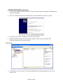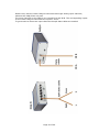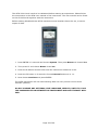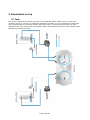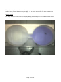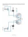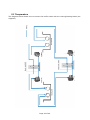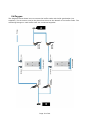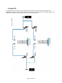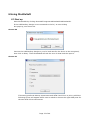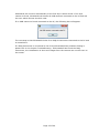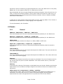
1
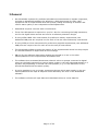
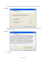
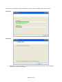
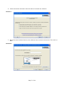
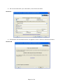
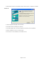
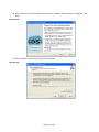
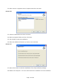
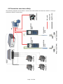
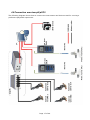
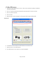
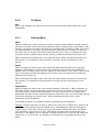
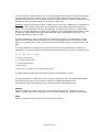
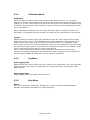
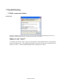
USER MANUAL
ShuttleSoft
1. List of parts
o
ShuttleSoft installation USB memory stick (Loligo®)
o
USB hardkey dongle (Wibu)
o
LabView Vison runtime license document
o
uEYE USB camera
§ C-mount lens
§ USB cable
§ Tripod adapter
§ Bracket
§ Software CD
o
DAQ-S or DAQ-M instrument
§ Adapter cables, qty. 4
§ DO-SET for oxygen/pH/pCO2 control, qty. 2
§ OR TMP-SET for temperature control, qty. 2
§ OR pump for salinity/turbidity control, qty. 4
§ Split data cable, qty. 4 (DAQ-M only)
o
o
o
o
o
OXY-REG for oxygen measurements, qty. 2
OR TMP-REG for temperature measurements, qty. 2
OR WTW COND 3310 instruments for salinity measurements, qty. 2
OR WTW pH 3310 instruments for pH/pCO2 measurements, qty. 2
OR TUR-REG for turbidity measurements, qty. 2
o
Flow through probe vessel, qty. 2 (Not included in turbidity)
o
User manual
Page 1 of 44
2. Contents
1.
List of parts ......................................................................................................... 1
2.
Contents ............................................................................................................. 2
3.
General ............................................................................................................... 3
4.
Installation procedure ........................................................................................... 4
4.1
ShuttleSoft software for Windows ........................................................................ 4
4.2
Connection overview salinity ............................................................................. 13
4.3
Connection overview temperature ..................................................................... 14
4.4
Connection overview oxygen ............................................................................ 15
4.5
Connection overview turbidity ........................................................................... 16
4.6
Connection overview pH/pCO2 .......................................................................... 17
4.7
uEye USB camera ............................................................................................ 18
4.8
DAQ-S/DAQ-M instrument ................................................................................ 19
4.9
WTW 3310 Cond instrument (salinity only) ......................................................... 21
4.10
WTW 3310 pH instrument (pH/pCO2 only) ......................................................... 23
5.
Experiment set up .............................................................................................. 25
5.1
Tank .............................................................................................................. 25
5.2
Salinity .......................................................................................................... 28
5.3
Temperature................................................................................................... 29
5.4
Oxygen .......................................................................................................... 30
5.5
Turbidity ........................................................................................................ 31
5.6
pH/pCO2 ........................................................................................................ 32
6.
Using ShuttleSoft ............................................................................................... 33
6.1
Start up ......................................................................................................... 33
6.2
New experiment .............................................................................................. 36
6.3
Details ........................................................................................................... 37
7.
TroubleShooting ................................................................................................. 42
7.1
DAQ connection failure.................................................................................... 42
7.2
Relays unresponsive ........................................................................................ 44
7.3
uEye camera connection failure......................................................................... 44
7.4
uEye camera settings ...................................................................................... 44
Page 2 of 44
3. General
·
Our ShuttleBox systems for preference/avoidance measurements in aquatic organisms,
includes an ShuttleSoft software for Windows, a DAQ instrument for USB, video
equipment and an experimental tank with pumps, tubing and fittings to monitor and
control water quality in two independent subcompartments.
·
ShuttleSoft requires a mouse with a scroll button.
·
Three free USB ports are required on your PC. One for connecting the DAQ instrument,
one for the digital video camera and one for a software protection dongle.
·
If using WTW COND 3310 instruments for preference salinity experiments, two
additional USB ports are required one for each of two the two conductivity instruments.
·
If using WTW pH 3310 instruments for preference pH/pCO2 experiments, two additional
USB ports are required one for each of two the two pH instruments.
·
The ShuttleSoft software tracks the position of the experimental animal on the principle
of contrast between an object and its surroundings.
·
ON-the-fly the software determines whether the animal is in one or the other
subcompartment of the experimental ShuttleBox tank.
·
The software then activates/deactivates solenoid valves or pumps connected to digital
relays on the DAQ instrument to control water quality in the two subcompartments in a
dynamic way depending on animal real-time position, e.g. it is the behaviour of the
animal that determines the water quality.
·
It is also possible to set up a static experiment during which water quality in the two
subcompartments are kept at setpoint levels defined by the user in the ShuttleSoft
software.
·
The software will save all input data and calculated values to a text data file.
Page 3 of 44
4. Installation procedure
Minimum PC requirements: ShuttleSoft requires Windows XP/Vista/7 running on a PC with an
Intel Pentium IV processor of 2 GHz and 2GB RAM or better. We recommend monitors with a
minimum resolution of 1024x768 pixels.
4.1 ShuttleSoft software for Windows
The following steps will explain how to install ShuttleSoft on your computer.Insert the USB
memory stick labelled Loligo and wait until you see the following screen.
Click Open folder to view files and double click on the icon labelled ShuttleSoft_Installer.exe.
Screen 1
1. Click Next to start installation of ShuttleSoft.
Screen 2
Page 4 of 44
2. Select destination directory for ShuttleSoft and LabView drivers and then press Next.
Screen 3
3. If you accept the License Agreement, please select “I accept the License Agreement(s)”
and then press Next.
Screen 4
4. Click Next.
Page 5 of 44
On Screen 5 the status of the installation is shown. The installation may take a while.
Screen 5
Screen 6
5. Click Next to end installation of ShuttleSoft and activate the product. This activation
requires an internet connection.
Page 6 of 44
6. Choose automatic activation and click Next to activate the software.
Screen 7
7. Enter the serial number found on the LabView Vison runtime license card. Then click on
Next.
Screen 8
Page 7 of 44
8. Fill out the fields with your information, when done click Next.
Screen 9
9. If activation was successful Screen 10 appears. Click on Finish to end the activation.
Screen 10
Page 8 of 44
10. Now install drivers for the hardkey dongle. When Screen 11 appears, click Next.
Screen 11
11. Select supported language, and click Next.
12. Click Next without changing any options.
13. Click Next again after you have accepted the summary of the installation.
14. When installation is done, click Next again.
15. Click Finish to end installation of the WiBu drivers.
Page 9 of 44
16. Now drivers for the uEye USB camera will be installed. When Screen 12 appears, click
Next.
Screen 12
17. Select unpack and remove, and then click Next.
Screen 13
Page 10 of 44
18. Wait for the files to be unpacked. The setup screen will appear when done.
Screen 14
19. Select “Install driver”.
20. Choose language and then click Next.
21. When Screen 15 appears click Next.
Screen 15
Page 11 of 44
22. When Screen 16 appears select Complete and then click Next.
Screen 16
23. Choose a destination and then click Next.
24. Select a program folder and then click Next.
25. Click Install to start the installation.
26. Select the additional features you want, then click Next
Screen 17
27. Select Click Finish to end the installation of the uEye software package.
28. Restart the Computer. You have now finished the installation of all the software.
Page 12 of 44
4.2 Connection overview salinity
The following diagram shows how to connect the instruments and devices used for running a
preference salinity experiment.
Page 13 of 44
4.3 Connection overview temperature
The following diagram shows how to connect the instruments and devices used for running a
preference temperature experiment.
Page 14 of 44
4.4 Connection overview oxygen
The following diagram shows how to connect the instruments and devices used for running a
preference oxygen experiment.
Page 15 of 44
4.5 Connection overview turbidity
The following diagram shows how to connect the instruments and devices used for running a
preference turbidity experiment.
Page 16 of 44
4.6 Connection overview pH/pCO2
The following diagram shows how to connect the instruments and devices used for running a
preference pH/pCO2 experiment.
Page 17 of 44
4.7 uEye USB camera
1. Connect the uEye USB camera to the PC. After a few seconds the software installation
will start automatically.
2. Click on “Install the software automatically (Recommended)” and then on Next.
3. Click on continue anyways.
4. Click on Finish.
5. Open the uEye camera manager by clicking StartàAll ProgramsàIDSàuEYE
Screen 18
6. If installation was successful, the uEYE camera is now shown here.
7. Mount the lens on the uEYE camera.
8. The uEYE camera is now ready for use with ShuttleSoft.
Page 18 of 44
4.8 DAQ-S/DAQ-M instrument
1. Connect the DAQ instrument to the PC. After a few seconds the software installation will
start automatically.
2. Click on “Install the software automatically (Recommended)” and then on Next
3. The drivers will now be installed, when done click Finish.
4. Open the Measurement and Automation Explorer (MAX) by clicking StartàAll
ProgramsàNational InstrumentsàMAX
Screen 19
5. If installation was successful, the USB-6008(DAQ-S)/USB-6009(DAQ-M) card is now
shown here.
Page 19 of 44
Please note, that the newer DAQ-M instrument has eight analog input channels,
whereas the DAQ-S has only two.
The input channels on the DAQ-S are named IN A and IN B. The corresponding inputs
on the newer DAQ-M instrument are inputs 1 and 2.
To get access to those two input channels the split data cables are needed.
Page 20 of 44
4.9 WTW 3310 Cond instrument (salinity only)
1. Connect the WTW Cond 3310 instrument to your PC. After a few seconds the software
installation will start automatically.
2. Click on “Install the software automatically (Recommended)” and then on Next. If
Winows cannot find the drivers, please insert the WTW disc.
3. The drivers will now be installed, when done click Finish.
4. Repeat step 1-3 for the second WTW Cond 3310 instrument.
Page 21 of 44
The WTW 3310 Cond needs to be calibrated before starting an experiment. Please follow
the instructions in the WTW user manual of the instrument. The user manual can be found
on the CD delivered together with the instrument.
Before starting ShuttleSoft the WTW instrument serial interface has to be set, to secure
export of data.
1. Press ENTER in 2 seconds and choose System. Then press Reset and choose Yes.
2. Then press F1 and choose Reset. Press Yes.
3. Press the M button several times until the instrument measures in Sal.
4. Press the F2 button in 2 seconds. Choose Interval and set it to 1 s.
5. Now choose Continue and press ENTER.
The WTW instrument will now start sending data out every second via the serial
interface (RS232).
DO NOT CHANGE ANY SETTINGS, LIKE LANGUAGE, SEND ID, UNIT ETC. ELSE
THE COMMUNICATION BETWEEN THE INSTRUMENT AND SHUTTLESOFT WILL
FAIL.
Page 22 of 44
4.10
WTW 3310 pH instrument (pH/pCO2 only)
5. Connect the WTW pH 3310 instrument to your PC. After a few seconds the software
installation will start automatically.
6. Click on “Install the software automatically (Recommended)” and then on Next. If
Winows cannot find the drivers, please insert the WTW disc.
7. The drivers will now be installed, when done click Finish.
8. Repeat step 1-3 for the second WTW pH 3310 instrument.
Page 23 of 44
The WTW 3310 pH needs to be calibrated before starting an experiment. Please follow the
instructions in the WTW user manual of the instrument. The user manual can be found on
the CD delivered together with the instrument.
Before starting ShuttleSoft the WTW instrument serial interface has to be set, to secure
export of data.
1. Press ENTER in 2 seconds and choose System. Then press Reset and choose Yes.
2. Then press F1 and choose Reset. Press Yes.
3. Press ENTER in 2 seconds and choose System. Then press Interface and then Output
format. Choose CSV and press ENTER. Leave the menu.
4. Press the F2 button in 2 seconds. Choose Interval and set it to 1 s.
5. Set SEND ID to Yes.
6. Now choose Continue and press ENTER.
The WTW instrument will now start sending data out every second via the serial interface
(RS232).
DO NOT CHANGE ANY SETTINGS, LIKE LANGUAGE, ETC. ELSE THE COMMUNICATION
BETWEEN THE INSTRUMENT AND CAPCTRL WILL FAIL.
Page 24 of 44
5. Experiment set up
5.1 Tank
Set up the shuttle tank system as shown in the diagram below. Make sure to check if the
direction of flow is correct. For optimum separation of flows, it is very important to that both
sub compartments are fed with exactly equal flow rates. To adjust the flow rate use tube
clamps on the hose going from each pump, and/or raise/lower the position of the buffer tanks
feeding the Shuttle box tank.
Page 25 of 44
To avoid mixing between the two sub-compartments, it is also very important that the water
surface level is equal between the two sides, i.e. to avoid water from one side entering the
other due to pressure differences (gravity).
System check
It is easy to check flows inside the tank by adding a colored dye to one side and follow it over
time. Please check the picture below for reference.
Page 26 of 44
Please note, that when running a turbidity experiment no probe vessels are used. Set up the
shuttle tank system as shown in the diagram below. Place the turbidity probes in the Shuttle
tank chambers directly.
Page 27 of 44
5.2 Salinity
The diagram below shows how to connect buffer tanks with water reservoirs (not supplied)
containing high and low saline water. The fittings in the middle of each buffer tank are used as
overflows.
Page 28 of 44
5.3 Temperature
The diagram below shows how to connect the buffer tanks with the cooling/heating baths (not
supplied).
Page 29 of 44
5.4 Oxygen
The diagram below shows how to connect the buffer tanks with O2/N2 gas bottles (not
supplied). The air stones need to be placed into down at the bottom of the buffer tanks. The
remaining fittings on each buffer tank are connected together.
Page 30 of 44
5.5 Turbidity
The diagram below shows how to connect buffer tanks with water reservoirs (not supplied)
containing turbid and clear water. The fittings in the middle of each buffer tank are used as
overflows.
Page 31 of 44
5.6 pH/pCO2
The diagram below shows how to connect the buffer tanks with air/N 2 gas bottles (not
supplied). The air stones need to be placed into down at the bottom of the buffer tanks. The
remaining fittings on each buffer tank are connected together.
Page 32 of 44
6. Using ShuttleSoft
6.1 Start up
Start ShuttleSoft by clicking StartàAll ProgramsàShuttleSoftàShuttleSoft.
If the USB hardkey dongle is not connected to the PC, an error dialog
box pops up, see Screen 20.
Screen 20
Connect the USB hardkey dongle to your PC and wait for the device to be recognized,
then click on Retry. Then ShuttleSoft will ask the user of what kind the input is.
Screen 21
If choosing preferred Salinity experiment and WTW Cond 3310 or pH or pCO2 the
following screen will appear where user is asked to choose the right COM ports for
the two WTW 3310 instruments.
Page 33 of 44
After choosing COM port, press Connect and ShuttleSoft will try to establish
communication with the two WTW 3310 Cond instruments. If connection was
successful, the OK button gets available, and the user can continue the
initialization by pressing OK.
Now Screen 22 will now appear.
Screen 22
Page 34 of 44
ShuttleSoft will connect automatically to the first uEye camera found. If no uEye
camera is found, ShuttleSoft will detect all USB cameras connected to the PC and ask
the user which camera should b used.
If no USB camera is found connected to the PC, the following box will appear.
The next step is that ShuttleSoft looks for a DAQ-S instrument connected to the PC and
is named dev1.
If a DAQ instrument is connected to the PC but ShuttleSoft has problems finding it
please look in the chapter TroubleShooting. If ShuttleSoft has found the DAQinstrument, the initialization is done and images from the camera can now be seen on
the screen.
Page 35 of 44
6.2 New experiment
To zoom place the mouse over the picture and use the scroll button to zoom.
1. Threshold tool. Start by clicking Show Binary and use the vertical threshold bars to
find the animal inside the Shuttle Box. Start by choosing a narrow range (short distance
between the 2 bars) and then use the right hand side slider to scan the image for your
animal. If necessary use the filter options found in SettingsàFilter to remove irrelevant
pixels in the picture. When done click Show Binary again to view unmodified images.
To avoid tracking any moving objects outside the Shuttle Box, click SettingsàMask to
draw a mask excluding areas outside the experimental tank for analysis. When done
click OK. The mask file can be saved for later use.
2. Pixel calibration. Now click CalibrationàPixel and use the mouse to draw a line along
an axis of a known distance in the image, e.g. place a ruler in the experimental tank.
Then enter the distance and unit for the line. The pixel-to-meter ratio is now calculated.
Click OK when done.
3. Define the two zones. Then click SettingsàZones, and draw two zones, one for each
of the two subcompartments. Any areas outside the two zones will be referred to as
OFF zone. We recommend leaving a narrow space between the two user-defined zones
corresponding to the short channel connecting the subcompartments. This to avoid
errors or misinterpretation associated with animals taking positions in the connecting
channel for prolonged periods of time. When done click OK.
4. Experiment settings. Now click Experiment and choose between a static or dynamic
experiment. Static means that the water quality in the two subcompartments is kept at
setpoint levels entered in the software by the user and independent of animal positions,
e.g. for choice/avoidance experiments.
Dynamic experiments means that water quality control in the two subcompartments will
depend on the behaviour of the experimental animal, e.g. when in one (INCR)
compartment the parameter setpoint (e.g. temperature) will increase, and when the
animal then shuttle to the other compartment, it will decrease, e.g. behavioural
thermoregulation.
For static experiments enter a setpoint and hysteresis for each zone. These can also be
changed during experiments.
For dynamic experiments, the user should enter a constant difference in either oxygen,
temperature, salinity or turbidity between the two compartments. The system will
maintain this difference - we call it the Delta value (± hysteresis). Depending on the
animals position, the valves/pumps will be activated/deactivated to keep a set
difference (Delta) between the two zones. During times when the animal is in the OFF
zone, the system will maintain the oxygen/temperature/salinity levels in the two zones
recorded prior to entering the OFF zone.
5. Sensor signal calibration. Click CalibrationàOxygen/Temperature/Salinity/Turbidity
to do a two-point calibration, converting analog inputs on channels IN A and IN B (or 1
and 2) into relevant units (% air sat, °C etc.). If using WTW Cond 3310 this is not
necessary. Refer the OXY-REG/TMP-REG/WTW Cond 3310 user manual for further
instructions on how to calibrate or service probes. Then decide if input IN A (or 1)
Page 36 of 44
should be used for monitoring oxygen/temperature in the (red) INCR zone or the (blue)
DECR zone. Do the same for IN B (or 2). When done click OK.
Now ShuttleSoft will show oxygen/temperature/salinity/turbidity values for the zone (or
tank) in which the animal is present. During times when the animal is in OFF zone, an
average between the oxygen/temperature/salinity/turbidity values in INCR and DECR
zones will be calculated.
6. Data file. To start writing experimental data to a file, click LogàStart. Then choose a
destination for the data file. To stop logging, click LogàStop.
To exit ShuttleSoft, click FileàExit.
6.3 Details
6.3.1.
General
INCR O2 / INCR temp. / INCR sal. / INCR turb.
This field indicates the current O2 saturation/temperature/salinity for the INCR zone.
DECR O2 / DECR temp. / DECR sal. / DECR turb.
This field indicates the current O2 saturation/temperature/salinity for the INCR zone.
Object zone
This field indicates whether the object is in INCR, DECR or OFF zone.
Object O2 / Object temp. / Object sal. / Object turb.
This field indicates the current O2 saturation/temperature/salinity that the animal is
exposed to.
Time INCR [s]
This field indicates how long the object has stayed the INCR zone. This value will be set
to 0, when user starts logging.
Time DECR [s]
This field indicates how long the object has stayed the DECR zone. This value will be set
to 0, when user starts logging.
Distance
In this field the distance moved by the object is calculated. The unit of measure can be
set via the menu for pixel to meter calibration. This value will be set to 0, when user
starts logging.
Velocity
In this field the velocity of the object is calculated once per second. Please note that the
object has to move at least a half pixel length from frame to frame to be obtained as a
movement.
Object mean O2 / temperature/ salinity / turbidity
In this field the mean value of the object O2/Object temp./Object sal./Object turb. is
calculated. This value will be set to 0, when user starts logging. During dynamic
experiments this value will approach the true preference value of the animal.
Page 37 of 44
FPS
This field shows the frame rate of the camera. If frame rate should be low, decrease the
resolution in the camera settings menu or use a faster PC.
Threshold bars
Use the bars to set the threshold used to find the binary picture. On the left bar it is
possible to set the range of the threshold values. The right bar is to move both sliders.
Example: The two sliders on the left are set to 40 and 70 and the red indication is
between them. Every pixel that has a value between 40 to 70 will be coloured red and
all other pixels will be coloured black. The slider on the right bar will stay on 55. Now
the user moves the slider to 110. The red indication on the left bar will now be between
95 and 125.
Show Mask
Use this button to toggle between unmodified video images and masked images.
Show Binary
Use this button to toggle between unmodified video images and thresholded images.
Show Trace
Use this button to enable/disable a trailing trace from being shown behind the moving
animal and set the duration of the trailing trace in seconds.
RE1
This diode indicator gives the relay status for relay 1. On relay 1 the oxygen
valve/heating pump for the INCR zone must be connected.
RE2
This diode indicator gives the relay status for relay 2. On relay 2 the nitrogen valve/
cooling pump for the INCR zone must be connected.
RE3
This diode indicator gives the relay status for relay 3. On relay 3 the oxygen valve/
heating pump for the DECR zone must be connected.
RE4
This diode indicator gives the relay status for relay 4. On relay 4 the oxygen
valve/cooling pump for the DECR zone must be connected.
Log
This diode will blink while logging. When moving the mouse over the diode, the actual
saving path will be shown.
Image
Here the video images from the camera is shown. When maximizing ShuttleSoft on
your PC monitor, the image will scale accordingly. Move your cursor over the image and
zoom/unzoom by using the scroll button on your mouse.
Parameter / Velocity / Distance graph
On these graphs the values vs. Time are shown, e.g. reading from the inputs IN A (or
1) and IN B (or 2). The y-scale can be changed by double clicking on the scale and
entering a new number. Right clicking will open a menu, where x-scale can be changed
etc.
Page 38 of 44
6.3.2.
File Menu
Exit
On exit the software will close the camera input and save all settings and then close
ShuttleSoft.
6.3.3.
Settings Menu
Mask
Opens a dialog box, where users may create a mask to avoid analysis outside areas of
interest. Use either one of the upper buttons to draw a closed figure in the image. Then
decide if you want to include or exclude the enclosed area by pressing either one of the
two upper buttons in the lower group of buttons. Below there is a button to undo the
last step, and one to clear the entire mask and start over. Also it is possible to invert
the drawn mask. Created masks can be saved or loaded as bitmap files for later use.
When maximizing the dialog box, the image will scale. When moving the mouse over
the camera, it is possible to zoom/unzoom the image via the scroll button on the
mouse.
Zones
Opens a dialog box where users may define the INCR and the DECR zone. Start by
drawing a closed figure. Then decide if the closed figure should be used as INCR or
DECRS zone by clicking either on the I-button or the D-button. Then draw a next closed
figure and choose this as the missing zone. Drawn zones can be saved or loaded as
bitmap files for later use.
When maximizing the dialog box, the image will scale. When moving the mouse over
the camera, it is possible to zoom/unzoom the image via the scroll button on the
mouse.
Experiment
Opens a dialog box where user may choose between a dynamic or static regulation of
the water quality. If choosing Static, ShuttleSoft will now regulate for each of the two
zones around the setpoints and hysteresis, e.g. 20°C and 0,2°C for the INCR zone.
ShuttleSoft will start cooling when temperature goes above 20,2°C and will stop cooling
as soon as temperature reaches 20°C. When temperature goes under 19,8°C
ShuttleSoft will start heating.
If choosing Dynamic, the animals position will determine the regulation.
Example: Oxygen saturation is 80% in INCR zone, and 70% in DECR zone. Delta is set
to 15. Now if the animal enters the DECR zone, ShuttleSoft will start decreasing the
oxygen value in this zone. When the oxygen saturation drops below 65%, and Delta
thus exceeds a value of 15% air sat., ShuttleSoft will also start decreasing oxygen
saturation in the INCR zone to maintain a constant difference of 15% air sat. Once the
Delta value is <15% air sat. the bubbling of nitrogen gas in the INCR zone will stop
again.
Page 39 of 44
Use a hysteresis value greater than 0 to avoid digital relays going on and off constantly
on the sharp edge of the Delta value, since this might cause a malfunctioning of the
solenoid valve or pump. The hysteresis value will also determine upper and lower limits
maintained by the system while the animal is in OFF zone.
Example: Oxygen saturation is 80% in INCR zone, and 70% in DECR zone. Hysteresis is
set to 1%. The animal enters OFF zone between the two tanks and stays there for a
while. Due to equilibration with the atmosphere, oxygen values will rise in both tanks.
Once the oxygen saturation in DECR zone reaches 71%, ShuttleSoft will activate a relay
to open the valve blowing nitrogen into the buffer tank connected to this tank until
oxygen saturation is back to 70%.
It is also possible to enter a maximum and minimum value for the parameters. If the
INCR value is greater than the maximum value ShuttleSoft will not increase the INCR
value by triggering RE 1 relay. The same goes for the DECR value, minimum value and
RE 4.
It is also possible to calculate the core temperature when temperature is chosen as
parameter. For the calculation of the body temperature Newton´s law is cooling is used.
Tb = Ta + (Ti - Ta ) × e - kt , where
Tb is body temperature
Ta is ambient temperatue
Ti is initial temperature
t is time (min)
k is the rate of change of core temperature (min -1 )
k is dependent of fish size and species, Stevens and Sutterlin (1976)
It is also possible to enable and enter a system maximum rate. If enabled ShuttleSoft
will calculate the rate of the system by which the INCR and DECR zones
increase/decrease and regulate if the rate exceeds the entered max rate.
Camera
Opens a dialog box where users may set the video settings and resolution of the
camera. Please note, that a change in the resolution requires a restart of ShuttleSoft.
Filter
Opens a dialog box where user may set the filter options.
Page 40 of 44
6.3.4.
Calibration Menu
Calibration
Opens a dialog box where users may convert image pixels into mm, cm or metres.
Change the length and/or position of the green line to match any known distance in the
image, e.g. a ruler. The length of the green line will show. Then choose the desired unit
of measure and enter the known distance. A pixel ratio will now be calculated and used
for all calculations.
When maximizing the dialog box, the image will scale. When moving the cursor over
the image, it is possible to zoom/unzoom the image via the scroll button on the mouse.
Oxygen
Opens a dialog box where users may calibrate/convert the input signal from the DAQ
instrument to %air sat/°C. The calibration is a 2-point calibration. Place the tip of the
probe connected as input IN A in a known solution and wait for it to stabilize. Press
Lock LO and write the %air sat./temperature value in the LO calibration field. Now place
the tip of the oxygen probe in a second known solution and wait for it to stabilize. Press
Lock HI and write the %air sat./°C value in the HI field.
Use a >>20% difference between the two calibration solutions to maximize the
accuracy of oxygen/temperature measurements. Finally, choose if the input should be
used as input for INCR or DECR zone. Do the same for input IN B.
6.3.5.
Log Menu
Start logging data
Opens a note field, where users may write notes for the experiment. Then a file prompt
opens and user must choose a destination for the data file. When pressing OK, data
logging starts.
Stop logging data
Stops logging data to the data file and closes it.
6.3.6.
Help Menu
About
This menu will open a dialog box, showing the version number of the ShuttleSoft
software and contact information for Loligo Systems.
Page 41 of 44
7. TroubleShooting
7.1 DAQ connection failure
Screen 23
The error shown on Screen 23 occurs, when the NI-USB 6008/6009 DAQ card has no
properly connection to the PC. This error can occur in 2 ways.
Name is not “dev1”
To change the device name, open the NI program called Measurement & Automation
(look for desktop icon). The following example on Screen 24 shows a simulated device
named as “dev1”. The NI-USB 6008 DAQ card is registered as “dev2”
Page 42 of 44
Screen 24
Right click with mouse on the “dev1”, and choose rename, or press F2. Change the
name to something different than “dev1”. In this example the name is changed to
“dev1simu”, see Screen 25.
Screen 25
Now change the device name of the NI USB-6008 DAQ card to “dev1”. The DAQ-S
instrument should now work properly with ShuttleSoft.
Page 43 of 44
Screen 26
Another USB device was improperly removed
If an USB device, like a USB memory stick, is not properly removed, while ShuttleSoft
is running, there can be a connection problem with the DAQ-S instrument. To solve this
problem, close ShuttleSoft. Then disconnect the USB cable between the PC and the
DAQ-S instrument. Wait 30 seconds. Then connect the cable and wait. When the green
diode on the front side of the DAQ-S instrument is flashing, the connection is reestablished. ShuttleSoft can now be opened again.
7.2 Relays unresponsive
Make sure the DAQ-S instrument is connected with a power cable, and the Power
button is ON.
7.3 uEye camera connection failure
Make sure that no other program is using the uEYE camera while using it in ShuttleSoft.
Only one software program at the time can acquire data from the camera.
7.4 uEye camera settings
To change camera settings on the uEYE camera, open uEye DEMO and set the settings.
Then click FileàSave parametersàto file.
Save the file and name it uEYE_Loligo.ini. Browse to the folder where ShuttleSoft is
installed. Backup the old file uEYE_Loligo.ini by renaming it to e.g.
uEYE_Loligo_backup.ini. Now copy the uEYE_Loligo.ini file to the folder and start
ShuttleSoft. The settings are now loaded.
Page 44 of 44