1
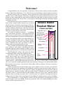
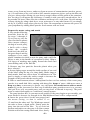
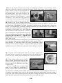
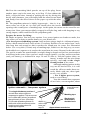
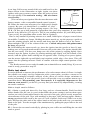
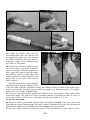
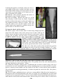
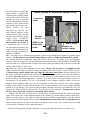
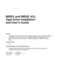
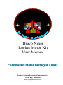
Educational Industries,
LLC
q =
√ T-mg
k
C6H22O11+
KNO3
Bravo Niner
Rocket Motor Kit
User Manual
“The Rocket Motor Factory in a Box”
October Science Educational Industries, LLC
Green Bay, Wisconsin
www.OctoberScience.com
-1-
Welcome!
Congratulations on your purchase of the Bravo Niner rocket motor kit from October
Science Educational Industries, LLC. Welcome to the fascinating world of amateur rocketry!
Model rocketry has, for decades, been considered an ideal educational activity for
adults to share with teenagers. Rocketry’s challenges, fun and excitement motivate young
people to learn math, physics and critical problem-solving skills. Rocket projects provide
the perfect material for science fairs, scout projects and simple Saturday morning outings
with Mom or Dad.
But until now, the typical consumer’s involvement with a model rocket launch has revolved
almost entirely around the construction of the airframe and recovery system. The established model
rocketry industry discourages curiosity about the
cross section
business end of rockets – how their motors work
Paper EC cap
and how to make them work better.
The field of amateur rocketry – as making
Black powder
one’s own motors is known – has been around for
ejection charge
many years, as reflected in recent Hollywood deEC pass-fire
pictions. Its popularity has grown dramatically in
Clear tape
recent years among adults, who often build very
Putty end cap
complex, ambitious rocket motors. But as strongly
as young people are drawn to the field, parents
Time delay
aren’t confident they have the skills or tools to
CPVC
safely make motors that perform well.
casing
Now, October Science brings small scale amateur rocketry to the public, providing the tools,
Propellant
materials and specific knowledge to allow young
people to make their own rocket motors that work
Hollow core
— while helping the adults who supervise them
to understand and control the inherent risks.
Putty
The Bravo Niner kit contains materials to
nozzle
build, from scratch, up to 40 solid fuel model
rocket motors, plus other materials to allow you
to fly the motors. Depending on your skill in building the motors, you should expect the power of a “B” motor, which means a total impulse
of 2.5 to 5 newton-seconds (producing the same amount of energy as a commercially-made
B6-4 motor). In any case, your motors, made right, will have plenty of power to produce
dramatic launches.
While the directions in this booklet may seem complex at first, we hope you will take
your time and enjoy the challenge of building the motors as much as the results. After you
make a few motors, you’ll see the process is fairly straightforward, and you’ll be able to
easily turn out a batch of motors with less than an hour of hands-on work. Keep in mind
also that of the 30 steps described in this booklet, nine are set-up steps (marked with an
asterisk) that need only be done once. Several more are related to testing and can be
skipped once you have some experience and confidence with the motors you are building.
Most importantly, a young builder’s pride will be tremendous in launching a rocket
made with his or her own hands, from top to bottom. His or her understanding of rocket
science will be much greater, too.
-2-
Bravo Niner
Rocket Motor
Rocket motor basics
All rocket motors, whether they use liquid or solid propellant, are powered by fuel and
oxidizer. Solid rocket propellant mixtures often contain small amounts of other chemicals
to improve their stability during the burn. Your motors will use sucrose as the fuel, potassium nitrate as the oxidizer, and sulfur to improve the burn characteristics.
Rocket motors are designed to produce very large amounts of gas, exhaust gasses, very
quickly. In your motors, 63 parts potassium nitrate (KNO3) and 27 parts sucrose (C6H22011)
combine to produce large volumes of water (H2O) and carbon dioxide (CO2) (plus smaller
amounts of some other gasses), in about half a second.
A very important part of your rocket motor is the nozzle. Here’s why: The rule E= M/2
2,
x V (energy equals one half the mass of an object, times its velocity squared) is importantly applied to the exhaust gasses of your motor. For example, if you had something that
weighted 10 grams and it were moving at 100 feet per second, its energy would be 50,000
(the units don’t matter here). If you ponder the equation E= M/2 x V2, you will realize that
doubling the mass doubles the energy, while doubling the velocity quadruples the energy.
In the case of a rocket motor, the thing that has mass is the exhaust gas, and the energy
equals the trust, or lifting power it can produce. The purpose of the nozzle, therefore, is to
increase the velocity of the exhaust gas. You’re pushing a specific amount of gas through
a hole in a specific amount of time (the chemical reaction won’t wait for the gas to escape!), so the smaller the hole, the greater the velocity.
Why not make the hole as small as possible? Rocket propellants tend to burn faster
when they are under more pressure. If you have too much pressure, the reaction of the
propellant is to produce more pressure, generally resulting in a blown nozzle or end cap.
There are two basic types of solid rocket motors. Most low-power commercial model
rocket motors are end burners. Their propellent starts burning near the nozzle, and burns
its way up the grain. The other kind are core burners. The propellent grain is made with a
hollow core. The grain is ignited at the same time up and down this core, and the propellent burns from the core outward.
The level of thrust produced by a rocket motor over the time of its burn can be plotted
on a graph to produce a thrust curve. The trust curve of commercially-made end-burning
model rocket motor of a “B” size or larger is characterized by a burst of power at the start
of the burn, followed by “throttle back” period of several hundred milliseconds. Core
burners, on the other hand, throttle up throughout the burn, producing the most thrust just
before the time delay begins. The amount of thrust produced at any give instant depends
mostly on the surface area inside the motor that is burning at that instant; the surface area
burning in a core burner increases as the propellant burns. (The motors you are about to
make have one basic characteristic in common with the massive solid rocket boosters on
the Space Shuttle: They’re both core burners.) It’s a great geometry exercise to calculate
the amount of propellent surface area burning inside your motor both at the start and at the
end of the burn.
-3-
A few important questions
One of the most common questions about this kit is, “Isn’t this dangerous?” The answer is yes, it can be. But then, so is riding a bike or boiling water on the stove. You must
understand and follow the directions carefully. The lightweight “stick rockets” described
in this kit will fly at more than 400 mph. Treat them with the respect due a firearm, and
use common sense.
An adult must closely supervise teenage children working with the materials in the
kit.
The greatest risk is for the nozzle or end cap at the top of the motor to blow out during
firing, shooting out chunks of intensely burning propellant at speeds in excess of 200 mph.
While this is rare with proper construction, you must be prepared for it any time you fire a
motor. For this reason, it is critical that the motor be in a vertical position any time it
is fired – that is, with the nozzle pointed straight up for a test stand firing, or straight
down for a flight. And obviously, everyone needs to keep their distance, and you must
keep the motor away from flammable materials.
Another danger comes from flying a rocket in a way that could allow it to hit someone.
The basic stick rockets described in this kit should fly stability when constructed as directed. Using them in kit rocket airframes or original design airframes requires, as always,
that you ensure the aerodynamic stability of your rocket before you launch it. The center of
gravity must be at least one body tube diameter forward of the center of pressure. (This kit
does not cover rocket airframe design issues. Refer to model rocketry handbooks for details.)
To be safe, you must fly these rockets at least 75 yards away from any bystanders.
The propellant materials in the kit, once mixed (and only then), are highly flammable,
and must be kept from any ignition source. (It is a worthwhile (and fun) exercise to take
about a teaspoon of the propellant mixture, place it in a small pile on some nonflammable
surface, and ignite it electrically as described in this handbook, to get a feel for the flammability of the mixture.) In two years of testing, there was never an incident involving an
unintentional explosion or flash fire of rocket propellent prepared as described here.
Users could burn themselves or injure themselves in other ways attempting to ignite a
motor with an open flame. You must use the electric method described in this handbook to ignite your motors. Bottom line: Read, understand and follow the directions to
the letter, and use common sense.
What about when they come down?
Stick rockets made from these motors are quite light; the risk of serious injury to
someone hit by a falling stick rocket is small. However, common courtesy dictates that
users take all reasonable steps to launch rockets in an area where there are no bystanders
who could be hit by a falling rocket. It would be dangerous to put one of your motors in a
regular rocket airframe with a hard nose cone and fins, unless you include an ejection
charge in your motor. Additionally, as with commercially-made motors, your ejection charge
could fail to deploy your recovery system, so again, you’ll want to be sure to launch your
rockets in a large, vacant area. (Please don’t litter. Recover all rockets.)
Is this legal?
Every municipality has its own laws regarding fireworks and model rockets. Often, rules
for model rockets are less strict than rules for fireworks. It is up to you to determine what
rules govern your rockets in your location, and to understand and comply with those rules.
-4-
Getting started
What you will need:
Your kit contains everything you need to make about 40 rockets, with the exception of a
few items that you probably have readily available. In addition to the items in your kit, you
will need:
• An empty coffee can
• Some sand or gravel
• A 6v lantern battery or larger battery.
(Car battery can be used.)
• A ruler with both metric and English
measures
• A 1/4 teaspoon measure
• Small containers for mixing putty
• Scraps of paperboard of the type used
for cereal boxes
• Cellophane tape, e.g. Scotch tape
• A large safety pin or similar sturdy,
sharp point
• A scissors
• A knife with a sharp point
• A hammer
• Masking tape
• A double beam balance accurate to
0.1 gram (optional)
• A cardboard tube at least 2 feet long
• A pole or narrow board about 2 feet long
To make a test stand you will also need a sturdy, smooth pole such as a broom handle,
some large, thick rubber bands, and a sturdy cardboard tube such as the type on which
plastic food wrap is wound.
Basic rocket instructions
About the process:
The basic instructions to build a rocket follow. You should read all the directions from
start to finish, twice, before you begin.
Start by making a batch of two or three simple motors without ejection charges. Test
your first batch on a stable test stand (see page 12) before flying anything, to ensure safety
and proper performance. When you’re sure you’ve got it right, fly a few simple rockets
using the sticks included in your kit. Do this in a large field away from any people. It’s
important to be able to find these simple rockets after flight so you can analyze them.
Then, make a batch with ejection charges, first firing them on the test stand with a stopwatch, and only then, if you wish, flying them in model rockets with parachutes or streamers – again, away from any bystanders. As with commercial motors, the ejection charges
on these motors sometimes fail to do the job, so you’re taking a risk. Don’t use them in
your prized showpiece rocket. Don’t use them in any model rocket until you have some
experience and confidence they’ll work as planned.
The steps:
1*. Dry the black powder slurry. Your kit contains a small container of black powder
(gunpowder) mixed with water for safety during shipping. To dry, simply open this container and put it in a safe place, away from any possible spark, flame or other intense heat
* Asterisks throughout booklet indicate a set-up step that only has to be done once.
-5-
source, away from any breeze, and away from an source of contamination (sawdust, grease,
etc.). Several times a day, stir it with a stiff, smooth, nonporous object, such as the butt end
of a pen. Always after stirring, do your best to scrape it down off the walls of the container.
In a few days it will appear dry but lumpy. Crumble it with your stiff, smooth object, let it
dry another 24 hours, then close the container and keep it in a safe place. Do not attempt
to hurry drying by using a hair dryer, oven, microwave or any other means. If you simply
air dry it, it will be ready when you need it. Note: Do not attempt to increase the power of
your propellant by adding black powder. Such motors will not work.
Prepare the motor casing and nozzle
2. Lay out the following
materials from the kit
for steps 3 through 8:
Up to four (try two for
your first batch) plastic
tubes (motor casings);
the bag of nozzle putty,
a knife with a sharp
point, the wooden
multi-tool, the drill bit,
the green dowel and the
sandpaper. Get a small
plastic container in which to mix the putty, and a stiff, flat
object to mix it (the handle of a teaspoon is fine). Wrap a
few layers of masking tape tightly around the chuck end
(non-drilling end) of the drill bit.
3. Remove any lose particles from the plastic tubes you
have selected.
4. Scrape light gouges around the inside surface of one end
of the tubes using the tip of a sharp knife. Make rings or
hatch marks from one end to about 10 millimeters in. The
goal is simply to make the surface rough to increase the
strength of the bond with the nozzle putty.
5. Place a small amount (about 1 tablespoon for three or four rockets) of the water putty
powder in a small dish. Mix, starting with about five drops of water. Add more water a
drop at a time, as necessary to form a very stiff paste. Be careful not to add too much
water. (If you do, just start over. Don’t try to add more putty powder to save it, or you may
find you’ll use way too much putty, and you may have to discard it anyway.) The paste
must be mixed thoroughly to a consistent, smooth texture.
The putty hardens fast, so you must work quickly. If the putty begins to get crumbly, you
must discard it because its strength in its final hardened state will be compromised.
6. Insert the green dowel in the non-gouged end
the motor casing, so that it comes 13 to
15 mm from the other end. Tip: Wind tape around
the tube to form a depth guide. Firmly pack the
putty into the end of the tube. Try to avoid air
pockets and make sure the putty is in firm contact
with the wall of the casing all around. Now, slowly
-6-
and carefully twist the dowel while holding it at a constant depth inside the tube. While continuing to turn, very
gently and slowly pull the dowel out. Wipe the excess
putty off the dowel and repeat this process for the other
remaining tubes in your batch. Set each tube on end on a
smooth, clean surface. Work as quickly as possible so the
putty does not harden too much before completing the
next step.
7. Form the basis for the nozzle: When the putty
is firm to the light touch (not jelly-like) insert
the puttied end of the motor casing in the large
hole on the green side of the wooden multi tool.
Insert the drill bit through the small hole in the
multi-tool opposite the motor casing, and press
down very gently while spinning the bit clockwise with your fingers. Tip: It’s helpful to
moisten the end of the drill bill. Drill until you
get all the way through the putty. Don’t worry if
a small chunk of putty drops outs the other end
when you break through, but if you see an obvious problem, your best bet is to knock out the
putty with the green dowel and start over.
8. Cut the sandpaper into four pieces. Forming a piece into a cone which diverges at a 15o
angle. Turn the sandpaper cone by hand to widen the aft (exposed) end of the nozzle so
that the bottom half of the nozzle diverges at a 15o angle.
9. Label each motor with a serial number. Record serial
numbers and any noteworthy aspects of motor assembly in a
notebook. Let the nozzle dry for 24 hours. Then make sure
the narrowest part of the nozzle is at least 9/64”
in diameter by checking with the drill bit..
Mix the propellant:
10*. Find a clean area away from any possibility of flame,
spark or other ignition source. Massage the bags of sucrose
and sulfur thoroughly with your fingers to break up all
lumps. Shake the bottle of potassium nitrate to break up all
clumps. For optimum performance, obtain a balance or scale
accurate to within 1/100 gram and measure 63 parts potassium nitrate, 27 parts powdered sugar, and 10 parts sulfur.
Discard any excess chemicals by pouring down the drain. Place the measured ingredients
together in a clean container, then return them to the plastic bottle that contained containing the potassium nitrate for mixing. The chemicals are pre-measured to a reasonable
degree of accuracy, so if you don’t have access to a good scale, just empty the contents of
the bags of sucrose and sulfur into the bottle containing the potassium nitrate. (Note that
the potassium nitrate container contains two small lead balls to improve mixing.) Close
the cover of the bottle tightly, take outside, and shake by hand moderately for 15 minutes.
Never attempt to mix these ingredients mechanically, such as with a blender or coffee
-7-
grinder. This mixture is referred to as “propellant.” Hand write on the bottle’s label,
“Sucrose-based rocket propellant.”
10 B. Note: It is important to keep this propellant mixture clean. Contamination with
small bits of foreign material can cause rockets to behave in unpredictable ways. Never
reuse spilled propellant. Gather it up and put it an airtight plastic “slop” container for
use later as primer. (See step 23.) Additionally, this mixture will absorb water from the
air, so you must keep the lid tightly on the container. It is best not to mix, handle or use it
when very high humidity is present.
Pack a basic motor:
11*. Make the core former by pounding one of the coring mandrels (nails) into the small
hole on the red side of the multi-tool so that its point extends
up through the center of the large hole on the opposite side.
You will, obviously, have to support its ends with something,
or place it over a hole drilled through the surface of your
work bench. Pound the nail in until its head is flush with the
red side of the multi-tool.
12. Weigh the casing/nozzle, if possible, and record. Place
the multi-tool red side down (nail sticking up) on a sheet of
clean paper on solid surface such as a sturdy work bench or
the floor.
13. Working on a hard surface such as a cement floor, place
the motor casing, nozzle down, over the coring mandrel, and
firmly into the multi-tool, so that the nail extends up through
the core of the casing. Look straight down into the casing – if the nail is obviously off
center, carefully bend it at its base to center it. Make a paper funnel and place it over the
open end of the casing. Using approximately 1/4 teaspoon at a time, put the propellent into
the casing and bump several times on a hard surface to get the propellent to settle down
around the coring mandrel. Never attempt to pack more than 1/4 teaspoon at a time.
14. Insert the red dowel, hole end down, into the motor casing and down over the point of
the coring mandrel. Pack the propellant down by striking the top of the dowel several
times with a hammer, using moderate force.
Angle the red dowel a few degrees this way and
that while striking it, to ensure the sides are
well packed. It is absolutely critical to use the
right amount of force during packing. Start by
“choking up” about two-thirds of the way on
the hammer handle and hammering as hard as
you can from the wrist – that is, moving your
elbow only 10o to 15o. It’s better to hit it too
hard and get it stuck on the multi tool than to
not hit it hard enough, in which case the grain
will be weak and the motor will blow its end
cap or nozzle). Do not place any part of your body over the top of the dowel while packing
the propellant.
As you work, propellant will collect in the hole in the center of the red dowel. Remove
-8-
it between rounds of packing by tapping it on a clean sheet
of paper.
Continue adding the propellant about 1/4 teaspoon at a
time, and packing, until the coring mandrel nail is just covered. If you don’t want an ejection charge, just add four
more 1/4 teaspoon scoops of propellant, packing down after each scoop using the clean end of the green dowel (the
end not used in step 6). Pack the last two rounds harder,
hammering from the elbow, and proceed
to step 15. If you want an ejection charge, you’ll need a
time delay. You can vary the time delay of your motors according to your needs. Measure the distance from the top of
the propellant grain (the top of the coring mandrel) to the top of the casing. It should be
around 25mm. We’ll call this distance the “potential TD gap” or TDP. Then continue
adding and packing propellant using the green dowel and measure the remaining distance
to the top of the casing. This is the “final TD gap,” or TDF . The ejection charge length
(TDL) is the potential TD gap minus the final TD gap. Or, TDL = TDP-TDF. Simply put, it’s
the distance the propellant extends beyond the mandrel.
Vary the TDF to control the TDL. Start with a TDL of 15mm and experiment on your test
stand. Again, remember to pack with more force on the last two rounds. The time delay
can also be lengthened by moving the opening in the forward closure from the center to the
side. See step 15.
Put any spilled propellant that is not significantly contaminated, and whatever you can
knock loose from the core of the red dowel, in your slop container. (See step 23.)
15. Forward closure: Cut a paperboard disk about equal to the outside diameter of the
motor casing. Note: If you want an ejection charge, follow the directions in italic and nonitalic type. If not, skip the stuff in italics. Fold the paperboard disk in half and use a
scissors to cut two slits in it to create a diamond-shaped opening 2 - 3 mm across when the
disk is unfolded.
The paperboard cut
from the center
must be completely
removed.
No
“hanging chads”
allowed. You can
experiment with
cutting the hole in
the forward closure so it is off to one side, to increase the
ejection delay, but you must ensure the tape can seal off the
hole completely.
Now place the paperboard disk on top of the motor and pack
it down with the green dowel using a few very light hammer
blows. The paperboard should form a shallow cup, with material coming slightly up the inside wall of the casing all the
way around. If the paperboard comes out when you pull out the dowel, simply stick it back
in with a pencil. Reinsert the dowel and “mash down” the edges by hand, forming a firm
seal around the casing wall.
-9-
Mark the top of the casing at four points, as if forming crosshairs, so you’ll know where
the hole is after the closure is covered with putty. With a large safety pin or similar point,
gently remove a tiny bit of propellant creating a tiny space. Put a bit of black powder in that space. Now cut a circle of cellophane (Scotch-type) tape 5-6 mm in diameter and push it firmly down – sticky
side down – over the hole. The goal is to
seal the hole so no moisture from the putty
you are about to add can get into the hole.
16. Remove the rocket motor from the
multi-tool. First gently pry using two screwdriver blades in the side holes as shown. Then
pull hard and twist slowly. Twisting vigorously could generate enough heat to ignite the
motor. You should hear a distinct creaking sound as you pull and twist. If you don’t, it
means the coring mandril is turning in the
wood base. If necessary, pry more: Placing
the screwdrivers under the motor as show in
the second photo at right (handles come up).
Then try pulling and twisting again. (Do not
pound or jam screwdrivers – a spark could
result). Once removed, weigh motor, if possible, and record.
17. Mix a small amount of nozzle putty. Two teaspoons putty powder with three drops water is about right for three motors. Place a
plug of putty 4-5 mm thick firmly over the paperboard closure
and tape. If no ejection charge is required, allow putty to harden
and skip to step 19. Otherwise, proceed without delay to step 18.
18. Use point of one of the small sticks in your kit to gently tease
the putty away to expose the taped-over hole. Be careful not to
pierce the tape. Allow putty to harden for at least three hours.
19. Using a large safety pin or similar
object, break through the tape at the
bottom of the putty cap hole, and do your
best to remove or obliterate all of the
exposed tape.
Crease a small piece of paper and
place on it a tenth of a teaspoon (0.5
grams, a bit less than a half of a quarter
tsp. measure) of black powder. Make sure the black powder is thoroughly dry. Pulverize it
to remove any lumps. Pour a bit of this powder into hole in the putty cap and, using a
safety pin, poke some powder down into the hole. Gently but firmly work to ensure some
black powder gets packed into the powder that was under the tape.
- 10 -
20. Pour the remaining black powder on top of the plug. Insert
another paper cap in the same way as in Step 15 (but without the
hole), except this time, instead of packing the cap by driving the
dowel with a hammer, you will simply hold the motor in one hand
and firmly force the dowel down on the paper cap with the other
hand.
21. The propellant mixture is highly hygroscopic – that is, it attracts water out of the air. As such you should close the nozzle
opening with a small piece of masking tape. At this point, the motor can be stored for use
at any time. Store your motors tightly wrapped in a Ziploc bag, and avoid dropping or any
strong impact, which could loosen the propellant grain.
Prepare the motor for firing:
22. Make an igniter: You have two options. Low power igniters are harder to make, but
they allow you to bring a smaller battery to your launch site.
• For lower power launching systems, such as those using a single 6 volt lantern battery:
Select a thick strand of steel wool, at least 13 cm long. Double over one end at least 3 mm,
then loop that end around so that it touches the strand near its center. See illustration
below. Use a very thin (3-5mm) strip of masking tape, folded over the long way, to secure
the doubled over segment as it touches the strand near its center. Repeat for the other end.
The goal is to make the strand double (or triple) along its length except for a portion about
4 mm long in the center. Once you have made a couple igniters, you may want to test them
(and your battery) as indicated in steps 29 and 30 (that is, with the igniter alone, no
motor), to make sure the wire burns
quickly, and only at the single
strand portion in its center.
Although making igniters in this
way can be hard at first, it is well
worth the effort to make them correctly. Made with care, these igniters are very reliable.
• For a higher power system,
such as a car battery:
Your kit contains three segments
of steel wire, woven together, about
Igniter schematic – low-power system
This single thickness section of
wire will burn when sufficient
amperage is applied. This area must
be in cotact with “primer” propellant
placed loosely in core. (See step
23.) Double strand segments on
either side of this area must not be
touching each other when full
amperage is applied.
Insert this end
in nozzle
Masking tape
Attach
micro clips
here, per
step 21
- 11 -
Single steel
wool strand,
doubled over
Approximate actual size
6 cm long. Pull out one strand of this wire and bend it to the
High-power igniter
shape shown in the illustration at right. Again, test these
igniters with your system to ensure it has the power to burn
Insert
the wire quickly. Use caution in testing – this wire burns
this end
very fiercely.
(You can always use igniters like the ones that come with
factory motors, with a compatible launch control system.)
23. Prime the motor (not necessary for a high-power launch
Connect clips here
system). By now you should have a container of “slop” –
spilled propellant left over from packing motors. (See step
10 B.) (If not, put a half teaspoon of propellent into your slop container) If your black
powder is dry add a bit (1/32 tsp) of it. This is your priming mixture. (If your black powder
is not yet dry, the propellant alone works fine as a primer.)
Place a tiny amount of priming mixture on a small, folded piece of paper creased down
the middle. Crumble any lumps. Holding the motor nozzle up, use the paper as a guide to
pour the priming mixture into the nozzle and down into the hollow core of the motor –
about enough to fill 1/3 of the volume of the core. Critical safety note: this primer must
be loose, not packed.
24. Still holding the motor nozzle up, insert the igniter into the nozzle at least 16 mm,
making sure no exposed metal touches from one side to the other. The igniter should slide
into the core easily. If it does not, dump out a bit of the primer by tapping lightly. Once
inserted, tape the igniter in place by placing masking tape firmly over the bottom of the
nozzle, with the igniter leads sticking out on opposite sides. If using a low power igniter,
turn the motor right-side-up and lightly tap it against a table edge a few times. This will
ensure that the priming mixture comes in contact with the single strand portion of the
igniter.
The Rocket motor is now ready for static (on an immobile test stand) firing. If your test
stand is ready, proceed to step S6.
Static test stand
It can be difficult to measure the performance of a rocket motor when it’s flown. A simple
but reliable test stand, used in conjunction with a cam-corder, provides a means to do
crude but meaningful scientific analysis of the effects of various design variations on
motor performance. It won’t be precise, but it will provide a way to compare motors on a
consistent basis. When making your first motors, it is especially important to fire
them on a test stand. If you do not, you may find your motors fly unpredictably, creating
an unsafe condition.
Make a simple stand as follows:
S1*. Obtain a wood pole about five feet long, such as a broom handle. Find four thick
rubber bands (like the one in your kit that holds the motor casings) and cut them open.
Anchor one end of each rubber band to the top end of the pole, spaced evenly around the
circumference of the pole. Tape with masking or duct tape, fold, and tape again. Obtain a
strong paperboard tube such as the core of a roll of plastic food wrap. Slide it on to the
pole, and tape the other end of the rubber bands to the tube in the same way you attached
them to the pole. Test the strength of the attachments by pulling the paper tube to the end
of the pole.
S2 *. Secure the test stand vertically by placing in your coffee can and filling the can with
sand or gravel.
- 12 -
S3*. Make an S hook with a piece of
coat hanger and place one end over the
top edge of the paper tube. Get a bucket
or similar container and add water to
bring the weight of the container plus
the water to 204 grams.
S4*. Place the container with the water
in it on the other end of the S hook so
that it is hanging from the paperboard
tube, jiggle the stand so that the paper
tube finds a neutral resting place, and
mark the position of bottom edge of the
paper tube on the pole with a heavy
black marker.
Add 204 ml of water to the container
and mark again. Repeat, adding 204 ml
water at a time, until the container reaches the bottom of the test stand. Each mark represents two Newtons. The peak thrust could be as high as 16 Newtons (about 3.5 pounds).
Make sure your stand can handle that.
S5. Go over each mark again, making the mark heavier. Then paint a white stripe under
each black mark. The goal is to create as much contrast as possible to make it easier to
record the results as viewed on a videotape. Number the marks 2, 4, 6 etc.
To use the test stand:
S6. Tape the motor, primed and with the igniter installed, securely to the paper tube with
masking tape, nozzle pointing up. Use three wraps of masking tape at the top and bottom
of the motor, then test by pusing down on the motor as far as possible.
S7. Set up a video camera on a tripod to record. The sun should be at the camera’s back.
- 13 -
Looking through the viewfinder, make sure the entire length of the pole is visible, and that you can
discern the marks clearly. For best results, set your
cam-corder to record images at 30 frames per second, if possible (SP setting).
S8. Roll the video camera, and fire the motor as
described in steps 29 and 30 below.
S9. Stop recording. Transfer the tape to a VCR
that can play it back frame by frame. Graph the
position of the rocket motor on the pole relative to
the numbered marks, frame by frame. This will
yield the thrust curve for the engine tested, and
simple math can be applied to estimate energy output in terms of Newton-seconds.
To launch a basic (stick) rocket:
25. Make a paper cone no more than 3/4 inch long. Simply tape the
paper into cone shape, trim to the correct size to mate with top of
rocket motor, and tape or glue in place directly to the motor casing,
taking care to make sure the cone is symmetrically centered.
SAFETY NOTE: If nose cone is more than 1 inch long, your
rocket’s center of pressure could
move forward of center of gravity, causing rocket to fly
wildly, like a released balloon. In addition to streamlining,
paper nose cone also helps reduce risk to people and property on the ground when the rocket comes down.
26. Take two of the thin wooden sticks included in your kit
and flatten one side of each for a length of about 1 1/2” starting from the blunt end. (Optional: Shave or sand the sticks to about half their normal
thickness.) Tape or glue the flat side of the stick to opposite sides of the rocket motor.
Make sure they are secure and straight. Note: The pointy end of the stick should point in
the same direction as the nozzle – down.
27*. Make the launcher: Simply take a cardboard tube at least 18 inches long, such as is
used for the core of a roll of gift wrap, and use masking tape to securely attach it to a stick,
dowel or narrow board. Make sure the inside of the tube is clear and in good condition.
The stick should extend approximately 16 inches beyond the end of the tube. (See photo,
facing page.)
28. Go to an open, uninhabited area, such as a vacant athletic field. Erect the launcher by
placing the stick or board attached to the tube in a coffee can, and filling the can with sand
or gravel on level ground. Point it 5o from vertical AWAY from launch team and observers,
and with the wind (wind at the launch team’s back as they face rocket). Place a solid, brick
- 14 -
or rock in the can under the
Stick rocket in launcher ready to fly
launch tube to support the
bottom of the rocket (pointy
end of the stick). It is imLauncher
portant to have a smooth
tube
surface that will prevent the
bottom of the rocket from
becoming stuck in any way.
Place rocket up into
launcher as shown. No
more than a quarter of the
rocket motor may extend
beyond the bottom of the
Rocket
paper tube. SAFETY
sticks
NOTE: It is critical that
Coffee can
the launcher be stable. If
Micro clips
a wind gust tips it over at
filled with
Bottom of
the moment of ignition, the
sand
rocket motor
rocket will travel horizontally, creating an extremely
unsafe condition.
29*. You may use a commercial ignition system and commercial igniters to ignite these
motors, but do not use your hand-made igniters with a commercial launcher system –
the current from the continuity light may ignite the motor. To make your own ignition
system, take the length of wire provided in your kit and remove the insulation from half an
inch of each wire, at both ends. Connect the micro clips provided with your kit to each side
at one end of this 15-foot wire.
30. Clean the clips with sandpaper if necessary. Make sure no power is supplied to the
wire, and attach clips to igniter leads extending from the nozzle of the rocket motor.
Critical safety point: Make sure the clips do not touch each other. Secure the wires so
the clips will not touch after the rocket launches. If using low-power (steel wool) igniters:
Connect one side (polarity is irrelevant) of the wire to a strong battery such as a six volt
lantern battery. If using high power igniters, you will need a stronger battery such as a
motorcycle or car battery. To use a car battery: First connect jumper cables to the car
battery. Then connect one wire of your launcher to the other end of one of the jumper
cables. Note: Don’t be concerned that the wire is much thinner what you would normally
attach to a car battery. The system will not draw enough current to overload the wire, as
long as the clips or leads to not touch.) Your rocket is now “armed.” You must be at least
15 feet away from the rocket or test stand when firing.
Make sure the area is clear. Give a loud, clear count down from five, then touch the
other side of the wire to the other terminal of the battery (or to the other jumper cable clip).
With a strong battery, the rocket motor should fire almost immediately, and the rocket
should launch within about half a second. Immediately remove the wires from the power
source upon ignition. If the motor does not ignite, remove the wires from the power and
wait at least 1 minute before approaching it.
* Asterisks throughout booklet indicate a set-up step that only has to be done once.
- 15 -
Critical Safety Points:
Always:
• Use remote electric means to ignite motors, whether on test stand or for
flight. Never attempt to ignite with a wick or fuse.
• Position the motor with the nozzle pointing straight up for test stand
firings, and at the ground for flights. Never ignite a motor that is
horizonal or near horizontal.
• Launch rockets in a large vacant area.
• Keep bystanders not directly participating in the launch or motor test
at least 75 yards away from a firing motor.
Kit component list
•
•
•
•
•
•
•
•
•
•
•
•
•
•
•
•
•
40 PCV motor casings
120 grams nozzle putty
239 g potassium nitrate, for use as propellant oxidizer
103 g sucrose, for use as propellant fuel
38 g flowers of sulfur, to stabilize propellant burn
Water slurry of black powder (gun powder) for ejection charge and
priming. Dry weight approx. 15 g.
1 wooden multi-tool, used in nozzle formation, and to support coring
mandrel
2 steel coring mandrels (modified nails), one of which will be joined to
the multi-tool, plus spare
1 9/64-inch drill bit, to form basis for nozzle (to be turned by hand)
Partial sheet of fine sandpaper
Red packing dowel with hollow core
Green packing dowel with solid core
40 thin wood sticks suitable for making 20 stick rockets. (Can be reused.)
44 strands of thin steel wire for use as high-power igniters
Wad of steel wool sufficient for making 40 optional low-power igniters
2 micro clips to attach wires to igniter for remote ignition
One length of two-strand wire, for remote ignition
October Science Educational Industries, LLC
2358 Jourdain Lane
Green Bay, Wisconsin
www.OctoberScience.com
920-430-1483
- 16 -
Rev. 3.0