1
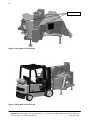
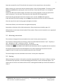
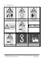
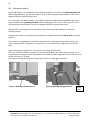
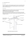
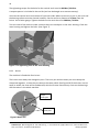
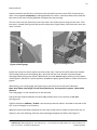
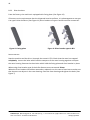
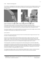
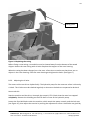
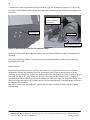
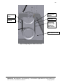
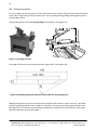
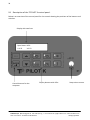
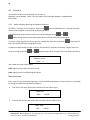
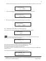
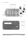
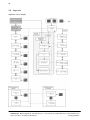
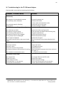
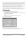
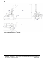
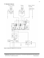
User Manual
&
Spare parts catalogue
for TP 320 wood chipper
in the forest series
Linddana A/S . Ølholm Bygade 70 . DK-7160 Tørring . T +45 75 80 52 00 . [email protected] . www.linddana.com
2
1
Introduction
Congratulations on your new TP wood chipper.
Linddana produces TP wood chippers of the finest quality by using the most modern production
technologies, such as laser cutting, CNC technology and robot technology in bright and open
production facilities.
For safety reasons and in order to reap the maximum benefit from the wood cutter, it is important
to read these instructions before use.
The user manual explains about safety, use and maintenance so that working with the wood
chipper will be safe and profitable.
This manual has been translated from Danish.
Linddana A/S
Jørgen Due Jensen, Managing Director
Your distributor is always available with spare parts, advice and guidance.
Distributor stamp
Linddana A/S . Ølholm Bygade 70 . DK-7160 Tørring . T +45 75 80 52 00 . [email protected] . www.linddana.com
User instructions: TP 320 from 28.04.2014
©Copyright 2012
3
2
EU-Declaration of Conformity
Manufacturer:
LINDDANA A/S, Ølholm Bygade 70, Ølholm, 7160 Tørring, Denmark
hereby declares that
Wood chipper:
______________________________________________
is in conformity with the requirements of the Machine Directive (Directive 06/42/EC) and with the
national legislation which translates this directive;
is in conformity with the following other EC Directives:
2000/14/EC
Furthermore it is stated that
EN 13525 (harmonised standard), has been applied.
Title: Managing Director
Name: Jørgen Due Jensen
Ølholm, 28. April 2014
Linddana A/S . Ølholm Bygade 70 . DK-7160 Tørring . T +45 75 80 52 00 . [email protected] . www.linddana.com
User instructions: TP 320 from 28.04.2014
©Copyright 2012
4
3
Contents
1
Introduction ........................................................................................................ 2
2
EU-Declaration of Conformity ............................................................................ 3
3
Contents.............................................................................................................. 4
4
Use ...................................................................................................................... 5
5
Mounting instructions ........................................................................................ 5
5.1
5.2
5.3
6
Before use......................................................................................................................... 5
Mounting instructions ....................................................................................................... 7
Starting ............................................................................................................................. 7
Safety instructions .............................................................................................. 8
6.1
6.2
6.3
6.4
Safety regulations ............................................................................................................. 8
Pictograms used................................................................................................................ 9
Noise level ...................................................................................................................... 10
Environmental instructions ............................................................................................. 10
7
Operation of the machine................................................................................. 10
8
Maintenance ..................................................................................................... 11
8.1
8.2
8.3
8.4
9
Maintenance schedule .................................................................................................... 11
Lubrication and oil .......................................................................................................... 12
Replacing worn parts ...................................................................................................... 13
Sharpening knives ........................................................................................................... 22
Instructions for TP PILOT K ............................................................................... 23
9.1
9.2
9.3
9.4
9.5
9.6
9.7
9.8
Description of the TP PILOT K control panel. ................................................................... 24
Functions ........................................................................................................................ 28
Calibration of the rollers on PVG32 machines. ................................................................ 29
Alarms ............................................................................................................................ 30
Please note ..................................................................................................................... 30
Technical data ................................................................................................................. 30
Electrical fittings ............................................................................................................. 31
Appendix......................................................................................................................... 32
10
Troubleshooting for the TP 320 wood chipper .............................................. 35
11
Warranty obligation for wood chipper .......................................................... 36
12
Technical data wood chipper ......................................................................... 37
13
Hydraulics diagram......................................................................................... 39
14
Accessories ..................................................................................................... 40
15
Spare parts catalogue ..................................................................................... 40
Linddana A/S . Ølholm Bygade 70 . DK-7160 Tørring . T +45 75 80 52 00 . [email protected] . www.linddana.com
User instructions: TP 320 from 28.04.2014
©Copyright 2012
5
4
Use
The TP 320 wood chipper is designed to make chipwood of trees, logs and branches which can be
fed into the machine with a crane or similar equipment.
The machine must not be used for materials containing stone, metal or other foreign bodies.
These foreign bodies will at least dull the knives and in the worst case can seriously damage the
machine. The knives and anvil can break when stone or metal comes in between them.
The machine must not be used for chipping wood containing nails, screws, reinforcements etc.
Remember to keep the knives and anvil sharp. This makes feeding in easier, and the chipwood
quality will be better, while it also reduces fuel consumption considerably.
The machine must be inspected daily, which means the rotor housing must be opened and the
rotor, knives, anvil etc. must be inspected. By doing this you prevent unexpected stops and
prolong the life of the machine.
The machine must not
·
·
Be used for other materials than wood
Be used to push trees, stubs etc.
Equipment like forest chains, axes, chain saws etc. must not be placed or transported in the
feeding hopper.
5
Mounting instructions
5.1 Before use
The machine has three lifting lugs, which must be used whenever it is lifted by a crane or other
lifting gear (with hooks). (See Figure 1) The machine can also be lifted with a fork lift truck, but
this must be done with great care as the machine might tip over. (See Figure 2)
Linddana A/S . Ølholm Bygade 70 . DK-7160 Tørring . T +45 75 80 52 00 . [email protected] . www.linddana.com
User instructions: TP 320 from 28.04.2014
©Copyright 2012
6
Lifting lugs
Figure 1 Lifting lugs on the machine
Figure 2 Lifting with a fork-lift truck
Linddana A/S . Ølholm Bygade 70 . DK-7160 Tørring . T +45 75 80 52 00 . [email protected] . www.linddana.com
User instructions: TP 320 from 28.04.2014
©Copyright 2012
7
Store the manuals for the PTO shaft with this manual in the manual box on the machine.
Before starting you must check that the wood chipper is free of foreign bodies. The tractor motor
must be stopped before opening the cover to the rotor. Check that the rotor is at a complete
standstill.
Loosen the bolts that hold the upper and lower rotor housing together. Lift the top part of the
rotor housing up. Turn the rotor a few times by hand. Remove any foreign bodies.
Check that the gap between the knives and the anvil is correct: 1.5mm. (See Figure 6)
From the factory the knife setting is set at 20mm. Check that the knives run clear of the anvils.
Close the top of the rotor housing again and tighten the bolts.
Check that all bolts, nuts and screws are tightened properly.
Remember to lubricate all the lubrication points. (See maintenance schedule, page 11.)
Old hydraulic oil and motor oil and used oil filters and air filters must be handed in at an approved
receiving station.
5.2 Mounting instructions
The machine is designed to be mounted on the tractor’s three-point-suspension.
The machine is delivered from the factory with a PTO shaft fitted with either 1 3/4" - 6 splines, 1
3/4" - 20 splines, 1 3/8" - 6 splines or 1 3/8" - 21 splines.
The PTO shaft must have a freewheel fitted on the machine side.
Linddana uses a Weasler WWCV shaft AB9-50 with freewheel, which is supplied with the machine.
The length of the PTO shaft must be adapted to the tractor following instructions from the
supplier of the PTO shaft. See the attached manual for the PTO shaft.
The wood chipper must be attached to the tractor’s three-point-suspension.
5.3 Starting
When starting the machine: the machine must be connected while the motor is idling or running
at the lowest rpm possible, to avoid overloading the PTO shaft, tractor and wood chipper. The
motor rpm can then be increased until the PTO is rotating above 1000 rpm. See further details in
chap. 9.
Linddana A/S . Ølholm Bygade 70 . DK-7160 Tørring . T +45 75 80 52 00 . [email protected] . www.linddana.com
User instructions: TP 320 from 28.04.2014
©Copyright 2012
8
6
Safety instructions
6.1 Safety regulations
·
·
·
·
·
·
·
·
·
·
·
·
·
·
·
·
·
·
·
·
·
·
The machine must not be fed manually, as it is exclusively designed for feeding by crane.
There is a security zone of 20 m around the tractor and the wood chipper. During
operation no one except the driver of the tractor is allowed in this area.
If people should come inside the security zone by accident, the emergency stop which
stops all movement by the crane and feeding into the wood chipper must be activated
immediately. Similarly, the emergency stop must always be activated before the operator
leaves the cabin.
When working near roads, signs must be displayed in accordance with the Road Traffic Act.
The machine must not be started without the ejector tube mounted to the machine.
Never use the machine in enclosed or poorly ventilated spaces, because of the danger of
carbon monoxide poisoning.
The top part of the machine and all other shielding must not be opened or removed before
the rotor disc is completely still and the tractor’s motor is stopped. It is possible to check
that the rotor has stopped completely by looking between the feed rollers.
Always stop the machine and the tractor during inspections, service or repairs.
The machine must be disconnected from the tractor PTO.
Do not use the PTO shaft as a step.
Tractor-mounted machines must be lowered to the ground before service or repairs are
done.
Always remove the ignition keys from the machine and/or the tractor before leaving it.
After maintenance and repairs, the machine must not be started before all bolts are
tightened and all safety devices are mounted.
Three-point mounted machines must be coupled to the tractor’s three-point- suspension
before use.
The maximum rpm for the machine (1100 rpm) must not be exceeded.
The tube shielding and covering on the transmission shaft must always be intact. Safety
chains on the transmission shaft must be properly mounted.
The length of the PTO shaft must be adapted to the tractor according to the
recommendations from the supplier of the PTO shaft.
Before the wood chipper is dismounted, any cranes that may be attached must be lowered
to the ground next to the machine.
During transport the ejector tube must be turned to point backwards in relation to the
driving direction and properly secured.
During transport on public roads, the requirements of authorities must be respected.
While the hopper is being cleaned to remove fine chipwood, THE RETRACTOR ROLLERS
MUST BE STOPPED.
A broom or the like must be used for cleaning. Never touch the inside of the hopper when
the machine is running.
IF THERE IS ANY DANGER: ACTIVATE THE EMERGENCY STOP IN THE TRACTOR
Linddana A/S . Ølholm Bygade 70 . DK-7160 Tørring . T +45 75 80 52 00 . [email protected] . www.linddana.com
User instructions: TP 320 from 28.04.2014
©Copyright 2012
9
6.2 Pictograms used
Warning: Objects thrown!
Safety distance 20m!
Warning: Rotating knives!
Wait for rotor to stop!
Warning: Must not be
manually fed!
Read the manual before use!
Warning: Rotating belts!
Max. Revolutions of the PTO
Warning: Rotating feed rollers!
Lifting lug for crane!
Lifting point for fork lift truck!
Linddana A/S . Ølholm Bygade 70 . DK-7160 Tørring . T +45 75 80 52 00 . [email protected] . www.linddana.com
User instructions: TP 320 from 28.04.2014
©Copyright 2012
10
6.3 Noise level
The sound effect level from the wood chipper has been measured during use with the rotor disc at
1000 rpm, powered by a tractor.
The measurements have been conducted according to test stipulations
Directive 2000/14/EC, 3 July 2000
EN ISO 3744, 1995
ISO 11201, 1995
ISO 4871, 19 March 1997
EN 13525, 2009
The sound effect level according to the warranty, which must be stated by the manufacturer
according to directive 2000/14/EC is as follows:
TP 320 wood chipper: 127 dB (A) re.1pW.
The values above are subject to the common uncertainty for the method of measuring and the
estimated variation in a product line for the type of machine. Detailed information on the
measurements and results and estimation of uncertainty are found in a detailed report which will
be supplied on request.
6.4 Environmental instructions
When changing hydraulic oil or engine oil, oil and used oil filters and air filters must be handed in
at an approved receiving station.
Oil spills must be avoided as far as possible. If oil spills occur, the spilled oil must be cleaned up
and handed in at an approved receiving station.
Worn out parts must be disposed of for recycling.
When the machine is worn out it must be disposed of properly. Hydraulic oil and engine oil must
be drained and handed in at an approved receiving station with oil filters and air filters.
The rest of the machine must be disposed of so that the materials are reclaimed.
7
Operation of the machine
When feeding wood into the machine, it is best to do this parallel with the machine and tractor
since this is the best way to get a good cut and a low use of energy.
The swinging feed roller can be opened by hydraulic power. (See details of how
under TP PILOT K.)
This can be used with advantage when feeding in large tree trunks and bundles of branches.
Linddana A/S . Ølholm Bygade 70 . DK-7160 Tørring . T +45 75 80 52 00 . [email protected] . www.linddana.com
User instructions: TP 320 from 28.04.2014
©Copyright 2012
11
8
Maintenance
During all maintenance and repairs the machine and the drive must be stopped. Tractor-mounted
machines must be placed on an even surface and be uncoupled from the tractor’s PTO.
8.1 Maintenance schedule
Interval=> hours
86
1
Lubricate the PTO shaft
X
Check the knives and anvil
X
2
Tighten all bolts and nuts
(X)
Check the hydraulic oil level
X
3
Oil the rotor disc main bearings
X
4
Lubricate the PTO shaft connector
Lubricate the roller bearings5
Replace the hydraulic oil filters6
Change the hydraulic oil7
Turn/replace the anvil8
Replace the bracket in the top rotor housing9
Turn or replace the triangle and square
scrapers10
Sharpen the retractor rollers 11
Check the V-belts 12
(X)
Check ejector wings for wear
Check casing for wear and tear
50 6 200 6 1000 6 1,000 m3 10,000 m3
X
X
X
(X)
X
X
X
X
X
X
X
X
X
1
Dismantle the PTO shaft and lubricate the seven lubrication nipples with Uniway Li62 or a
product of similar quality.
2
Tighten bolts and nuts, the first time after 8 hours and then at intervals of 50 hours.
3
Lubricate the two lubrication nipples with Uniway Li62 or a product of similar quality.
4
Dismantle the PTO shaft and pull the tube connection apart, clean and lubricate it.
5
Lubricate the two lubrication nipples with Uniway Li62 or a product of similar quality.
6
Change for the first time after 50 hours and then every 1000 hours. High pressure and return
filter elements.
7
Drain the hydraulic oil and fill with new oil using 112 litres of Hydraway HVXA 46 or oil that has
the equivalent specifications. The interval between changing oil can be extended by using
biodegradable hydraulic oil, such as the type Hydraway SE 46 HP and taking oil samples on an
ongoing basis.
8
Turn or change the anvil as necessary.
9
Change the bracket in the top rotor housing, if fitted, as necessary.
10
Turn or replace the triangle scrapers in the rotor housing. Turn or replace the square scraper on
the rotor.
11
Grind the retractor rollers sharp.
12
Check the tightness of the V-belts.
Linddana A/S . Ølholm Bygade 70 . DK-7160 Tørring . T +45 75 80 52 00 . [email protected] . www.linddana.com
User instructions: TP 320 from 28.04.2014
©Copyright 2012
12
8.2 Lubrication and oil
The Wood Chipper is as standard, factory-filled with hydraulic oil of the type Hydraway HVXA 46.
When replacing the oil, use the same type of oil or oil with equivalent specifications. Do not mix
together different types/brands of oils.
As an accessory, the Wood Chipper can be delivered factory-filled with biodegradable oil of the
type saturated ester, Hydraway SE 46HP. When replacing the oil, use the same type of oil or oil
with equivalent specifications. Do not mix together different types/brands of oils.
Old hydraulic oil and engine oil and oil filters and air filters must be handed in to the local
receiving station.
Lubricate the nipples according to the maintenance schedule with Statoil Uniway Li62 or a similar
product.
The machine is equipped with a hydraulic oil tank which is integrated in the rotor housing. The
tank is equipped with a filling filter, a return filter, an air release valve, a sight glass and a drain
plug.
When changing the hydraulic oil, unscrew the drain plug. (See Figure 3)
Drain the oil into a suitable container for proper disposal. When the tank is almost empty, use a
suction device to empty the tank completely. Screw back the drain plug and fill new hydraulic oil in
slowly (112 litres for TP 320).
Pour the oil through the filling filter (see Figure 4) until the sight glass is half full.
Figure 3 Draining off hydraulic oil
Figure 4 Refilling with hydraulic oil
Level
glass
Linddana A/S . Ølholm Bygade 70 . DK-7160 Tørring . T +45 75 80 52 00 . [email protected] . www.linddana.com
User instructions: TP 320 from 28.04.2014
©Copyright 2012
13
8.3 Replacing worn parts
8.3.1 Anvil
The anvil in the machine is used as wearing bar for the knife in order to cut the wood. The anvil
must be sharp-edged; otherwise the wood will bend down and the cut will become frayed. The
machine is equipped with one horizontal anvil with two edges and one vertical anvil with four
edges. Both anvils can be turned.
How to do this:
Stop the machine and the drive. Uncouple the tractor’s PTO. Check that the rotor has stopped
completely. Swing out the revolving roller to give access to the anvils.
Loosen the bolts that hold the upper and lower rotor housing together.
Lock the rotor with the rotor lock. (See Figure 9)
Remove the four bolts which hold the horizontal anvil. This is done from the outside and from
below. Take out the anvil and turn or replace it. Before the anvil is put back, the anvil and the
bearing surface must be cleaned carefully. The distance between the knife edge and the anvil must
be 1.5mm. (See Figure 6)
Vertical anvil
Distance between
knife and vertical/
horizontal anvil
Facing plate
Sliver breaker
Type A/B
Horizontal
anvil
Knife
Figure 6 Distance between anvil and knife
Linddana A/S . Ølholm Bygade 70 . DK-7160 Tørring . T +45 75 80 52 00 . [email protected] . www.linddana.com
User instructions: TP 320 from 28.04.2014
©Copyright 2012
14
The tightening torque for the bolts for the vertical anvil must be 200 Nm / 20 KPm.
A torque spanner is included in the tool kit (and can be bought as an extra accessory).
Unscrew the vertical anvil and remove it from the inside. Before a new one is put in, the anvil and
the bearing surface must be cleaned carefully. Set the anvil at a distance of 1.5mm from the
knives. Use a feeler gauge. Tighten the bolts on the vertical anvil to 200 Nm / 20 KPm.
Turn the rotor a few times to make sure that there are no objects in the rotor housing. Close the
rotor housing and tighten the bolts. (See Figure 7)
Figure 7 For tightening bolts in the rotor housing
8.3.2 Knives
The machine is fitted with four knives.
The knives must always be changed in pairs. The inner pair and the outer pair must always be
sharpened together, so that they are always the same width. (See Figure 18) If the knives are not
equal in width, the rotor will be unbalanced, which will cause unnecessary strain on the bearings
and vibrations in the whole machine.
Inner
knife pair
Outer
knife pair
Figure 8 Rotor disc
Linddana A/S . Ølholm Bygade 70 . DK-7160 Tørring . T +45 75 80 52 00 . [email protected] . www.linddana.com
User instructions: TP 320 from 28.04.2014
©Copyright 2012
15
How to do this:
Stop the machine and the drive. Disconnect the machine from the tractor PTO. Check that the
rotor is has stopped completely by looking between the rollers. Loosen the bolts which hold the
two parts of the rotor housing together and open the rotor housing.
Turn the rotor until the fork of the rotor lock covers one of the ejector wings on the rotor. Then
the rotor is locked. (See Figure 9) Be careful to keep your fingers away from the knives when the
rotor is turned.
Figure 10 Knife gauge
Figure 9 Locking the rotor
Loosen the three nuts which attach the knife to the rotor. Take out the knife and sliver breaker.
The bearing surfaces on the chipping disc, the knife and the sliver breaker must be cleaned
thoroughly before fitting the knives. When fitted, the nuts must be lightly oiled (m=0.125) which
means light oil, WD 40 or a similar product. Do not use copper grease, MoS2 or similar low friction
grease.
When fitting, use a knife gauge (see Figure 10) to set the knives at the correct distance.
Note: Max 20mm chip length in hard wood (deciduous). Corresponds to approx. 15mm knife
distance.
The knife gauge is in the manual box on the machine.
Check that the distance between the knife edge and the anvil is set correctly at 1.5 mm.
(See Figure 6)
Tighten the bolts at 200 Nm / 20 KPm. Use the torque wrench which is included in the tool kit for
this. It can be bought as an accessory.
When the knives have been replaced, turn the rotor a few times to make sure that there are no
objects in the rotor housing. Close the rotor housing and tighten the bolts. (See Figure 7)
Linddana A/S . Ølholm Bygade 70 . DK-7160 Tørring . T +45 75 80 52 00 . [email protected] . www.linddana.com
User instructions: TP 320 from 28.04.2014
©Copyright 2012
16
8.3.3 Sliver breakers
From the factory, the machine is equipped with facing plate. (See Figure 12)
If there are strict requirements that the chipwood must be uniform, it is advantageous to use type
A or type B sliver breakers. (See Figure 11) Sliver breakers of types A and B are extra accessories.
Figure 12 Facing plate
Figure 11 Sliver breaker types A & B
How to do this:
Stop the machine and the drive. Uncouple the tractor’s PTO. Check that the rotor has stopped
completely. Loosen the bolts which hold the two parts of the rotor housing together and open
the rotor housing. Remove the three bolts which hold the facing plate and sliver breaker in place.
When using sliver breaker type B, the knife distance must not exceed 15mm.
When the sliver breakers have been removed or replaced, turn the rotor a few times to make sure
that there are no objects in the rotor housing. Close the rotor housing and tighten the bolts. (See
Figure 7)
Linddana A/S . Ølholm Bygade 70 . DK-7160 Tørring . T +45 75 80 52 00 . [email protected] . www.linddana.com
User instructions: TP 320 from 28.04.2014
©Copyright 2012
17
8.3.4 Scrapers and facing plate
The machine is equipped with three square scrapers on the rotor disc, two triangle scrapers in the
rotor housing, two scrapers on the rotors outer diameter and a facing plate in the ejector tube.
(See Figure 13)
Figure 13 Positions of scrapers, square scraper, facing plate and triangle scraper
The purpose of the scrapers is to remove material that can get stuck by the knives.
At the same time the scraper and the square scraper removes material which falls off in front on
the chipping disc. This reduces the wear on the casing and reduces the consumption of fuel.
The square scrapers can be turned once before being replaced, while the triangle scraper and the
facing plate should always be replaced when they are worn.
How to do this:
Turn the rotor until the fork of the rotor lock covers one of the ejector wings on the rotor. Then
the rotor is locked. (See Figure 9)
Remove the countersunk bolts which hold the square scraper in place on the rotor. Turn the
square so that a sharp corner points up. Clean the block and the bearing surface. Mount the
square scraper. If it is worn on two corners, the square scraper must be replaced. Always replace
the square scrapers on the rotor in sets. Replace the triangle scraper when it is worn.
The facing plate is mounted in the top part of the rotor housing and can easily be replaced by
removing the three bolts on the outside of the rotor housing. If chip quality is not important the
facing plate in the ejector tube can be removed with advantage. This will increase the capacity of
the machine and save fuel. The facing plate must be removed when chipping wet conifer wood
with a lot of needles. Then good ejection is ensured.
To change the triangle scraper, remove the M12 bolt which holds it in place. It can be removed
through the hole where one of the outer knives is fitted. (The knife must be removed.)
Linddana A/S . Ølholm Bygade 70 . DK-7160 Tørring . T +45 75 80 52 00 . [email protected] . www.linddana.com
User instructions: TP 320 from 28.04.2014
©Copyright 2012
18
The scrapers mounted on the rotors outer diameter are replaced in sets when they no longer
exceed the diameter of the rotor. Remove the countersunk bolts which fasten the scrapers to the
rotor. Clean the surfaces and mount the new scrapers.
When mounting scrapers, use thread lock.
When the scrapers have been turned or replaced, turn the rotor a few times to make sure that
there are no objects in the rotor housing. Close the rotor housing and tighten the bolts.
(See Figure 7)
8.3.5 Casing
The TP 320 is equipped with replaceable casing at the bottom of the rotor housing. The casing
absorbs the wear and tear which would normally occur at the bottom of the rotor housing.
How to do this:
Stop the machine and the drive. Uncouple the tractor’s PTO. Check that the rotor has stopped
completely. Remove the axle around which the moveable part of the rotor housing rotates.
Remove the top part of the rotor housing and the facing plate.
Remove the six bolts and nuts which attach the casing to the bottom part of the rotor housing.
(See Figure 14) Loosen the casing and the casing can be swung out.
Linddana A/S . Ølholm Bygade 70 . DK-7160 Tørring . T +45 75 80 52 00 . [email protected] . www.linddana.com
User instructions: TP 320 from 28.04.2014
©Copyright 2012
19
Facing plate
Figure 14 Replacing the casing
Before fitting a new casing, rust and dirt must be cleaned away from the bottom of the wood
chipper. Mount the new casing with six bolts. Replace the top part of the rotor housing.
When the casing has been changed, turn the rotor a few times to make sure that there are no
objects in the rotor housing. Close the rotor housing and tighten the bolts. (See Figure 7)
8.3.6 Adjusting the V-belts
The retract rollers are driven hydraulically. The hydraulic pump for the retractor rollers is driven by
a V-belt. The V-belts must be checked regularly or whenever the belts are suspected to be slack.
How to do this:
Stop the machine and the drive. Uncouple the tractor’s PTO. Check that the rotor has stopped
completely. Remove the shielding on the PTO shaft in front of the hydraulic pump.
Loosen the four M12 bolts under the machine, which attach the pump console, and the lock nuts
(see Figure 15), then adjust the tension by turning the adjustment screws. Used belts may yield by
Linddana A/S . Ølholm Bygade 70 . DK-7160 Tørring . T +45 75 80 52 00 . [email protected] . www.linddana.com
User instructions: TP 320 from 28.04.2014
©Copyright 2012
20
7.26 mm when they are pressed down with 67 N (6.7 kg). For new belts the figure is 77 N (7.7 kg).
(See Figure 15) The belt tension can be measured with a suitable gauge, which can be bought as an
accessory.
Measuring point
in the middle of
belt section
M12 bolts
Lock nuts
Adjustment screws
Figure 15 Adjusting the V-belt for the hydraulic pump
When the V-belts have been adjusted, tighten the lock nuts and M12 bolts again and replace the
shielding.
The rotor is driven by V-belts. The V-belts must be checked regularly or whenever the belts are
suspected to be slack.
How to do this:
Stop the machine and the drive. Uncouple the tractor’s PTO. Check that the rotor has stopped
completely. Remove the shielding from the PTO shaft in front of the hydraulic pump, and the
shielding over the belt drive. Loosen the M20 cylinder bolts which hold the V-belt console, and the
lock nuts (see Figure 16), then adjust the tension by turning the adjustment screws. Used belts
may yield by 8.10mm when they are pressed down with 108 N (10.8 kg). For new belts the figure is
125 N (12.5 kg). (See Figure 16) The belt tension can be measured with a suitable gauge, which can
be bought as an accessory.
When the V-belts have been adjusted, tighten the lock nuts and M20 cylinder bolts and replace
the shielding.
Linddana A/S . Ølholm Bygade 70 . DK-7160 Tørring . T +45 75 80 52 00 . [email protected] . www.linddana.com
User instructions: TP 320 from 28.04.2014
©Copyright 2012
21
Adjustment
screw
Adjustment
screw
Lock nut
Lock nut
Measuring
point in the
middle of
belt section
M20 Cylinder bolts
Figure 16 Adjusting the V-belt for the rotor
Linddana A/S . Ølholm Bygade 70 . DK-7160 Tørring . T +45 75 80 52 00 . [email protected] . www.linddana.com
User instructions: TP 320 from 28.04.2014
©Copyright 2012
22
8.4 Sharpening knives
It is very important for the quality of chips that the knives are sharp. They must be checked at least
once a day. The grinding interval of the knives can be prolonged by grinding them regularly with a
carborundum stone.
The grinding process must be wet grinding with a header. (See Figure 17)
Figure 17 grinding machine
The edge of the knives must be ground at an angle of 30°. (See Figure 18)
Figure 18 Grinding angle and minimum knife width for the chipping disc
When grinding knives you must ensure that the width of the knives is equal in the set. The width
must be equal to keep the rotor in balance. Therefore, the knives must always be ground in sets.
(See Figure 17) The knives must not be ground down to a width of less than 165mm. (See Figure
18) After that they must be discarded.
Linddana A/S . Ølholm Bygade 70 . DK-7160 Tørring . T +45 75 80 52 00 . [email protected] . www.linddana.com
User instructions: TP 320 from 28.04.2014
©Copyright 2012
23
9
Instructions for TP PILOT K
Overall description of the system
During normal operation of the machine, the desired chip size can be set by setting the position of
the knives and typing in the setting of the knives, then calibrating the rollers. The wood chipper is
now ready for use: set the knife rpm higher than the set start value, at which the rollers start
pulling in wood material. As long as the rpm of the rotor is between the low and high limit values,
the rollers will rotate so the material between the rollers will be pulled towards the knives. The
rpm of the rollers will be adjusted to the rpm of the knives so the desired chip size is maintained.
The control works on a basis of an rpm signal from the rotor run by the tractor’s PTO and
revolution signals from both rollers. These signals are used to control two proportionally
controlled hydraulic valves, one for each roller. The hydraulic valves control the flow of oil to the
oil engines and thereby the rpm of the rollers. Because the rpm of the knives and the rollers are
synchronised, the material will be chipped in the desired size.
It is recommended that the 12 V power supply is run through an emergency stop button which
cuts off the power supply to the PILOT K and the crane.
Linddana A/S . Ølholm Bygade 70 . DK-7160 Tørring . T +45 75 80 52 00 . [email protected] . www.linddana.com
User instructions: TP 320 from 28.04.2014
©Copyright 2012
24
9.1 Description of the TP PILOT K control panel.
Below is an overview of the control panel for the control showing the positions of the buttons and
switches.
Display with two lines
Rpm Rotor: 1150
V1: 52
V2: 52
Control buttons for the
computer
Display buttons with LEDs.
Snap-action contact
Linddana A/S . Ølholm Bygade 70 . DK-7160 Tørring . T +45 75 80 52 00 . [email protected] . www.linddana.com
User instructions: TP 320 from 28.04.2014
©Copyright 2012
25
9.1.1 Display
Overviews of all the control’s displays and descriptions of each display can be found in appendices
1 and 2.
Setting the display contrast.
To set the display contrast, hold
button or
the button down, and at the same time press the
button.
Work display.
The work display shows the rpm of the rotor and the two rollers.
Rpm Rotor: 1150
V1: 52
When the
displays:
-
button or
V2: 52
button is pressed, the display navigates between the following
Showing the rpm of the rotor.
Rpm Rotor:
1150
-
Showing the rpm of the rollers.
Rpm Rollers
V1: 52
-
V2: 52
Showing the current knife setting in millimetres. It is possible to change the value
Knife setting
25
-
ENTER
Showing the time for the present job. It is shown in hours and minutes. It is possible to
reset to 0.
Job Time
1:48
ENTER
-
Linddana A/S . Ølholm Bygade 70 . DK-7160 Tørring . T +45 75 80 52 00 . [email protected] . www.linddana.com
User instructions: TP 320 from 28.04.2014
©Copyright 2012
26
-
Showing the total work time of the machine. It is shown in hours and minutes.
Total Time
10:18
-
The current temperature of the oil in degrees Celsius.
Oil temperature
26 C
If the rollers are not calibrated, this display will be shown.
Not Calibrated
ENTER
This display will also be activated when the knife setting and the RPM STOP value are changed.
button is pressed, the display will be deactivated, but it will be activated again if the
If the
rotor rpm increases above the start value.
The displays shown are also available through a specific display button described below.
(See also
Appendix 1 User display.)
9.1.2 The computer control buttons.
The computer control buttons are described below.
Display change and changing entry values.
ENTER button.
Change to entry display, approving an entry and start calibration.
The ESC button is used to delete a value that has been entered, or to leave a given
display and go to the preceding display. Pressing repeatedly will always call up the
work display.
Linddana A/S . Ølholm Bygade 70 . DK-7160 Tørring . T +45 75 80 52 00 . [email protected] . www.linddana.com
User instructions: TP 320 from 28.04.2014
©Copyright 2012
27
9.1.3 Display buttons with LEDs.
Changes the display to show the rpm of the rotor. When the display is active, the LED
will light up.
Changes the display to show the knife setting that was entered. When the display is
active, the LED will light up. It is possible to change the value of the knife setting.
Changes the display to show oil heating. When the display is active, the LED will light
up. Press a second time and hold the button down for two seconds to start the oil
heating.
The oil heating will only start if the oil temperature is lower than "Temp. Oil Heating”
or if no sensor has been fitted.
If a sensor has been fitted, the oil temperature will be shown.
If a sensor has not been fitted, the time from the start of heating will be shown in
minutes.
When the oil is heating an LED will flash.
The oil heating will stop when the temperature reaches "Temp. Oil Heating”. Or by
pressing the button again.
Changes the display to show the rpm figure for the rollers. When the display is active,
the LED will light up.
If the control is put in reverse, an LED will light up no matter which display is showing,
in order to indicate that the rollers are in reverse.
If the percentage difference between the rollers is larger than the entered value, the
LED will flash no matter which display is shown. At the same time there will be a
sound alarm.
Display changes to show the time registered for the job. When the display is active,
the LED will light up. Pressing a second time will change the display to show the
machine’s total time. It is possible to reset the job time to 0. Push ENTER in for two
seconds.
Changes the display to show the oil temperature. When the display is active, the LED
will light up.
If a sensor has been fitted, the current temperature will be shown.
If a sensor has not been fitted, and "Temp. Oil Heating” is less than 99 the error
message "Sensor error” will be shown.
If a sensor has not been fitted, and "Temp. Oil Heating” is 99, the message "Sensor not
installed" will be shown.
9.1.4 Switch for machine operation
The switch will move to the middle position when it is not being pushed.
The upper switch will mean that the rollers will open to "release". When the switch is
released, the rollers will close to "press together".
Short pressure down will cause the rollers to reverse the number of pulses which have
been set in the control.
Holding the switch down will cause the rollers to reverse as long as the switch is held
down.
For both functions a sound alarm will be heard at the same time.
Linddana A/S . Ølholm Bygade 70 . DK-7160 Tørring . T +45 75 80 52 00 . [email protected] . www.linddana.com
User instructions: TP 320 from 28.04.2014
©Copyright 2012
28
9.2 Functions
An overview of the control displays can be seen in
Appendix 1 User display. There is an overview of the individual displays in Appendix #2
Description.
9.2.1 General display showings and button functions
must be held down for 2 seconds to allow
If "ENTER ”is shown on the display it means that
values to be changed or to activate underlying displays.
A flashing value means that the value can now be changed using
and
.
always brings the previous display back and will finally show the work display.
If a value is flashing and you do not want to change this value then just press
leave the display without changing the value.
. Then you will
A code must be entered in order to access the machine’s functions and setup. To gain access to
enter the code, press the
and
buttons down for 2 seconds. Then the display will show.
Machine setup
Code
0
User codes are code 3 and code 5.
Code 3 gives access to the machine setup.
Code 5 gives access to calibrating the rollers.
Machine setup
Enter code 3 in the code entering display. Then the following display is shown, where it is possible
to change the different machine parameters:
·
The rpm of the rotor where the retraction of the rollers starts
RPM start
1000
·
ENTER
The low rpm of the rotor where the retraction of the rollers stops.
RPM Stop
850
ENTER
Linddana A/S . Ølholm Bygade 70 . DK-7160 Tørring . T +45 75 80 52 00 . [email protected] . www.linddana.com
User instructions: TP 320 from 28.04.2014
©Copyright 2012
29
Number of pulses the rollers reverse when they are stopped because of low rpm of the rotor.
Pulses Reversing
15
·
ENTER
There is a waiting period of 1/10 second before the revering function starts.
Rollers backoff wait
0.6 sec
·
ENTER
Minimum temperature for starting the retraction of the rollers.
Temp. Oil Heating
20 C
ENTER
9.3 Calibration of the rollers on PVG32 machines.
Enter code 5 in the code entering display. Then the following display is shown
Not Calibrated
ENTER
If
is held down for two seconds the machine will start calibrating the calculation of the
rollers’ rpm. This is shown in the display below.
560 Calibrating
35
32
The value on the top line to the left is the current PWM value (0 - 1000).
The value on the top line to the right is the intended roller rpm.
The value on the bottom line is the current roller rpm.
The calibration results in a calculation formula to convert the desired roller rpm to a PWM value
(electrical value).
If the calibration cannot be done the following display is shown:
500 Calibrating
64
Can not be done
Linddana A/S . Ølholm Bygade 70 . DK-7160 Tørring . T +45 75 80 52 00 . [email protected] . www.linddana.com
User instructions: TP 320 from 28.04.2014
©Copyright 2012
30
The reason why the calibration cannot be done may be one of the following:
· There is insufficient flow of hydraulic oil to the rollers.
· The rpm on the tractor by which the calibration is done is too low.
In both cases, it can be resolved by increasing the rpm of the rotor to 1000 rpm during calibration.
9.4 Alarms
Alarms are always activated with sound.
There are alarms for:
- Temperature sensor fault.
- Temperature too low.
- Temperature too high.
- Too big difference in the rpm of the rollers.
- Both rollers are stopping.
- Manual reverse of rollers.
- Manually opened rollers.
Temperature alarms and roller alarms are sounded with 5 beeps.
Manual reverse and manual open rollers are sounded with 2 beeps.
9.5 Please note
Please note that welding must not be carried out on the machine where the control is mounted,
before disconnecting all cables, power supplies, sensors, communication etc. from the control,
and it is recommended that the ground cable for the welder is placed close to where the welding
is going to take place. If these recommendations are not followed, the control may be irreparably
damaged.
9.6 Technical data
Power supply
+12V dc
Temperature range
0°C – 50°C
Fuse
T5A/250V
Linddana A/S . Ølholm Bygade 70 . DK-7160 Tørring . T +45 75 80 52 00 . [email protected] . www.linddana.com
User instructions: TP 320 from 28.04.2014
©Copyright 2012
31
9.7 Electrical fittings
External functions
External "rollers
open" function
External reverse
function
Linddana A/S . Ølholm Bygade 70 . DK-7160 Tørring . T +45 75 80 52 00 . [email protected] . www.linddana.com
User instructions: TP 320 from 28.04.2014
©Copyright 2012
32
9.8 Appendix
Appendix 1 User display
Linddana A/S . Ølholm Bygade 70 . DK-7160 Tørring . T +45 75 80 52 00 . [email protected] . www.linddana.com
User instructions: TP 320 from 28.04.2014
©Copyright 2012
33
Appendix #2 Description of user display
Start display.
Display
Linddana wood chipper
Version: 1.15 TP320
Description
Information:
Shows the software version and selected machine type
9.8.1 Work displays.
Display
Rpm Rotor: 0
V1: 0
V2: 0
Description
Information: (Main display)
Current rpm on rotor.
Current rpm on roller 1 and roller 2.
Rpm Rotor:
Information:
0
Current rpm on the rotor alone. Can be used if this
information is overwritten by error messages in the
main display.
Rpm Rollers
Information:
V1: 0
V2: 0
Current rpm of the rollers alone. Can be used if this
information is overwritten by error messages in the
main display.
Knife setting
Information:
25
ENTER
Knife setting in mm. Can be changed by holding the
enter button down for two seconds.
Job Time
Information:
0:16
ENTER
Current job time in hours and seconds. The job time is
only registered when the rollers are running.
The job time can be reset by holding the enter button
down for two seconds.
Total Time
Information:
00:16
Shows the machine’s total work time in hours and
minutes.
The total time is only registered when the retractor
rollers are running.
Oil temperature
Information:
26 C
The current temperature of the hydraulic oil in degrees
Celsius.
Oil temperature Sensor not Information:
installed
The sensor is not fitted and "Temp. Oil Heating" is set at
99.
Oil heating
Information:
10 C
The current temperature of the hydraulic oil in degrees
Celsius.
Information:
Oil heating
Sensor not installed
The sensor is not fitted and "Temp. Oil Heating" is set at
99.
Linddana A/S . Ølholm Bygade 70 . DK-7160 Tørring . T +45 75 80 52 00 . [email protected] . www.linddana.com
User instructions: TP 320 from 28.04.2014
©Copyright 2012
34
Display
Oil heating
10 minutes
Description
Information:
The sensor is not fitted and "Temp. Oil Heating" is set at
99. Shows how long the oil heating has been activated.
9.8.2 Machine calibration (Code 5)
Display
Not Calibrated
ENTER
558 Calibrating 31
29
Calibrating done
Enter/Esc
500 Calibration 72
Can not be done
Description
Information:
The machine is not calibrated. Start calibration by
holding the ENTER button down for two seconds.
Information:
Calibration has begun.
The value on the top line to the left is the current PWM
value.
The value on the top line to the right is the intended
roller rpm.
The value on the bottom line is the current roller rpm.
Information:
Calibration is completed.
Press enter to save the values required for the formula
for calculating the PWM value of the rollers.
Press Esc and the calibration can be repeated.
Information:
The calibration cannot be done. Insufficient flow of oil to
the rollers.
9.8.3 Machine setup (Code 3)
Display
Description
Rpm start
Information:
1000
ENTER
Rotor rpm for start of retraction.
Rpm Stop
Information:
850
ENTER
Value of stop for retraction at too low rotor rpm.
Pulses Reversing
Information:
15 ENTER
Desired number of pulses the rollers are to reverse.
Rollers backoff wait
Information:
0.6 sec ENTER Desired waiting time before the automatic reverse
function is activated.
Temp. Oil Heating
Information:
26 C
The temperature the oil must reach before start of
retraction is started.
This value must be set at 99 if the sensor has not been
fitted.
Linddana A/S . Ølholm Bygade 70 . DK-7160 Tørring . T +45 75 80 52 00 . [email protected] . www.linddana.com
User instructions: TP 320 from 28.04.2014
©Copyright 2012
35
10 Troubleshooting for the TP 320 wood chipper
Check possible causes before contacting the distributor.
Problem / Possible cause
Solution
The rollers are not turning round
satisfactorily:
Not enough oil in the hydraulics system
The stationary roller is blocked
The revolution guard is blocking
Wrong speed
The rollers are not pulling satisfactorily:
Fill up with hydraulic oil
1) Reverse the rollers
2) Clean under and behind the roller
Increase the rpm on the rotor
Check the settings in PILOT K
The V-belts are too slack
The hydraulic oil gets too hot
Poor viscosity of the hydraulic oil
The hydraulic filter(s) is/are clogged
The oil pump is worn or damaged
The oil engine is defective
The pressure control valve in the control valve
is dirty
Chip quality is not satisfactory:
Tighten the V-belts (see Figure 15)
Let the machine cool down while checking why
Change the hydraulic oil
Replace the hydraulic filter(s)
Replace the hydraulic pumps
Replace the oil engine
Clean the pressure control valve (Danfoss PVG
valve)
The knives are blunt
The anvil is worn
The knives are worn too far down
The distance between knife and anvil is too big
Sharpen the knives
Turn/replace the anvil
Replace the knives
Adjust the distance between the knives and anvil
(see Figure 7)
Fit or replace the sliver breaker
Sliver breaker not mounted or worn
Poor ejection of the chips:
Not enough drive
Scrapers are worn
Ejector wings are worn
The facing plate is in the top part
Too low rpm on the machine
Not enough effect on the PTO shaft
Replace the scrapers
Replace the ejector wings
Remove the facing plate from the top part
Increase speed to maximum revolutions
Linddana A/S . Ølholm Bygade 70 . DK-7160 Tørring . T +45 75 80 52 00 . [email protected] . www.linddana.com
User instructions: TP 320 from 28.04.2014
©Copyright 2012
36
11 Warranty obligation for wood chipper
The warranty is valid 12 months from date of purchase to rectify defects that demonstrably are
due to defects in materials or workmanship. The warranty covers faulty components which will be
repaired or replaced.
Transport costs and wages for replacements are the responsibility of the customer.
When any claims are made, the replaced parts must be sent to Linddana for examination.
Linddana alone decides whether the claim can be approved.
The following is an excerpt from Linddana’s Terms of Sales and Delivery (items 4 and 5).
Claims
Any risk related to the goods shall pass to the customer when the goods are delivered. Complaints
about a delivery shall be made in writing to Linddana as soon as possible, and not later than eight
days after the goods are received. If Linddana has not received the complaint within the stated
time limit, the buyer's right to complain about quality or quantity shall lapse.
Linddana shall be entitled and under an obligation to remedy all defects caused by faults of design,
materials or production. Linddana itself shall decide whether remedial action shall be in the form
of repair or replacement of the defective part or parts. Where repairs are carried out, the buyer
shall be obliged to deliver the item sold to a workshop indicated by Linddana, and collect it, at no
cost to Linddana. When the defective part or parts are replaced, the buyer shall be obliged to send
the defective parts to Linddana at no cost to Linddana. Linddana shall be entitled to deliver a
substitute product to replace defective products.
Linddana's liability covers only defects that appear within a year from the date when the product
sold was delivered.
Linddana shall not be liable for defects other than those mentioned in this clause. This applies to
any loss that may be caused by the defect, including operating loss, or loss of earnings and other
consequential financial loss.
Warranty terms
If Linddana has accepted that a guarantee shall be provided, this will cover errors and defects in
design, materials or production. A guarantee issued by Linddana shall not cover defects or
deficiencies that are due to inadequate maintenance, incorrect installation, alterations made by
the buyer or incorrect use of the product. Furthermore, the warranty shall not cover normal wear
and tear. Linddana's obligations under the warranty shall be conditional on the buyer's
documentation that any ascertained defect or deficiency has not been caused by circumstances
excluded from the warranty; cf. above.
Linddana A/S . Ølholm Bygade 70 . DK-7160 Tørring . T +45 75 80 52 00 . [email protected] . www.linddana.com
User instructions: TP 320 from 28.04.2014
©Copyright 2012
37
The buyer shall inform Linddana of faults or defects in the product sold, not later than eight days
after the defect is discovered or should have been discovered by the buyer. If the buyer does not
inform Linddana before this time limit has expired and before the warranty period has expired, the
buyer shall forfeit the right to make any claims arising from the defect or deficiency.
Linddana is entitled and obligated to remedy any faults which are covered by a warranty granted
by Linddana. Linddana alone decides whether the remedy shall take the form of repairs or
replacement of the defective parts, everything under the terms stipulated in item 4.
Linddana has no other liability for those defects. This applies to any loss that may be caused by the
defect, including operating loss, or loss of earnings and other consequential financial loss.
The guarantee does not cover:
·
·
·
·
·
·
·
Defects that can justifiably be attributed to inappropriate use.
Use of non-genuine spare parts, including wearing parts.
Incorrect adjustment or use of the machine. This includes the knife settings for hard wood.
Use of wrong lubricant or hydraulic oil.
Wear on the cross on the PTO shaft.
V-belts.
Knives and anvil which break because of foreign bodies in the machine.
12 Technical data wood chipper
Type
TP 320 PTO K
Chipping principle
Disc chipper
Rotor disc diameter, mm
1050
Number of revolutions PTO rpm
1000
Number of revolutions rotor rpm
1000
Number of knives, items
4 (2 cuts/rev.)
Effect requirement min/max kW/(HP) 95-184/(130-250)
Max. Wood diameter, mm
320
Chip length, mm*
12 -30
Weight, kg
2500
Height, mm
3466
Width, mm
1781
Length, mm
2191
* In hard wood (deciduous) max. 20 mm.
PTO transmission shaft: Weasler WWCV Shaft AB9-50 with freewheel.
Rights reserved to changes in the construction and specifications without previous notice.
Linddana A/S . Ølholm Bygade 70 . DK-7160 Tørring . T +45 75 80 52 00 . [email protected] . www.linddana.com
User instructions: TP 320 from 28.04.2014
©Copyright 2012
38
Figure 19 Dimensioned sketch TP 320 PTO K
Linddana A/S . Ølholm Bygade 70 . DK-7160 Tørring . T +45 75 80 52 00 . [email protected] . www.linddana.com
User instructions: TP 320 from 28.04.2014
©Copyright 2012
39
13 Hydraulics diagram
Figure 20 Hydraulics diagram for TP 320 PTO K
Linddana A/S . Ølholm Bygade 70 . DK-7160 Tørring . T +45 75 80 52 00 . [email protected] . www.linddana.com
User instructions: TP 320 from 28.04.2014
©Copyright 2012
40
14 Accessories
·
·
Tool kit including torque spanner
Sliver breaker type A/B (Figure 11)
15 Spare parts catalogue
Linddana A/S . Ølholm Bygade 70 . DK-7160 Tørring . T +45 75 80 52 00 . [email protected] . www.linddana.com
User instructions: TP 320 from 28.04.2014
©Copyright 2012