1
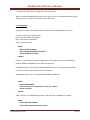
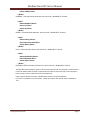
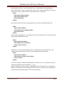
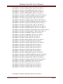
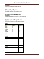
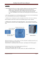
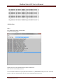
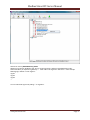
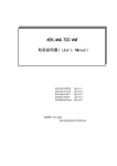
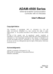
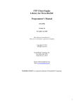
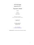
Modbus Slave OPC Server Manual Document name : Modbus slave OPC server user manual Version : 1.0.1 Date : Q1 2012 Revision changes : adding Modbus TCP functionality Author : Kamjoo bayat [email protected] For any support, please contact [email protected] Content 123456- Introduction Installation Configuration Operation Sample configuration Product specification www.pbsControl.com Page 1 Modbus Slave OPC Server Manual 1 - Introduction pbsControl company developed an OPC server which has Modbus slave functionality . We used pbsModbusS_OPCSrv module In many projects for Local HMI Connection and higher level Control system connection . We are using Win-Tech OPC engine, which is a leader in OPC server development toolkit and Microsoft C# language for developing our OPC servers. In following figure , you can see Modbus Slave OPC Server architecture and operation . www.pbsControl.com Page 2 Modbus Slave OPC Server Manual 2 – Installation pbsModbusS_OPCSrv is tested on following operating systems : - Windows XP professional - Windows XP embedded 2009 - Windows Vista - Windows 7 - Windows server 2003 and 2008 ( 32 and 64 bit) pbsModbusS_OPCSrv is developed by C#, so you need to have Microsoft Dot net framework 3.5 runtime on your system . Please download and install from www.microsoft.com . (you can install from product CD ) For OPC functionality, you need to install OPC runtime 2.0 on your PC. Please download it from form link: ftp.pbscontrol.com user = opcuser password = opc_2012 directory name : OPCredist2 You can download demo version of pbsModbusS_OPCSrv from following link: ftp.pbscontrol.com user = opcuser password = opc_2012 directory name : pbsModbusS_OPCSrv Demo version has full functionality, but it works for 30 minutes every time you restart it. Registered version is located on FTP Site for each client with dedicated User name and password. You can find all software in products CD . Copy files from pbsModbusS_OPCSrv directory to a local directory in your PC . You will see following files in pbsModbusS_OPCSrv directory : 1 - pbsModbusS_OPCSrv.exe : this is main OPC module . You will run this module when you want to run OPC server. 2 - PbsModbusSlave32.dll pbsControl modbus Slave implementation. This is 100% C# managed code library. 3 – pbsOPCSrvAPI.dll Wrapper class for OPC Server toolkit . 4 – WtOPCSvr.dll OPC server API . This is C++ implementation of OPC standard. 5 – ModbusTags.xml modbus tag definition. www.pbsControl.com Page 3 Modbus Slave OPC Server Manual 6 – options.xml option file for setting OPC server parameters . When you execute pbsModbusS_OPCSrv.exe for the first time, it will update windows registry. After that you can connect to OPC server by any OPC Client. 3 – Configuration Edit Options.xml file with notepad editor. You will see following parameters in this file : For each node there are 3 parameters: Name = Fix part and do not change it Desc = Description of Parameter Value = Parameter Value. <Node> <Name>Protocol</Name> <Desc>ModbusRTU,ModbusTCP</Desc> <Value>ModbusTCP</Value> </Node> Protocol = Communication protocol . ModbusRTU ( for serial communication with RS232 , RS422 or RS485) and ModbusTCP for Ethernet connection . For RS485 network , you should use Rs485 to RS232 converter or using any External RS485 serial ports with Automatic flow detection functionality . pbsModbusS_OPCSrv.exe is using RS424 and RS485 like RS232 Port . <Node> <Name>COM</Name> <Desc>Serial Port for Communication 1,2,3,4,5,...</Desc> <Value>1</Value> </Node> COM = Serial port for ModbusRTU protocol . Just will use for ModbusRTU Protocol . <Node> <Name>BaudRate</Name> <Desc>Communication baud rate </Desc> www.pbsControl.com Page 4 Modbus Slave OPC Server Manual <Value>57600</Value> </Node> BaudRate = Communication baud rate. Just will use for ModbusRTU Protocol . <Node> <Name>DataBit</Name> <Desc>7,8</Desc> <Value>8</Value> </Node> DataBit = Communication Data Bits. Just will use for ModbusRTU Protocol . <Node> <Name>Parity</Name> <Desc>None,Even,Odd</Desc> <Value>None</Value> </Node> Parity = Communication Parity. Just will use for ModbusRTU Protocol . <Node> <Name>DtrEnable</Name> <Desc>DtrEnable</Desc> <Value>False</Value> </Node> DtrEnable= DTR functionality of Serial Port. Just will use for ModbusRTU Protocol . The DTR( Data Terminal Ready) signal is one of the most important call control signals on a data modem. It is the most reliable method by which a computer tells the modem to disconnect (end) a call. Dropping the DTR from high to low for at least 2 seconds accomplishes this. DTR is using for Modem Connection . Set DtrEnable to False for using without Modem . If you want to use Modem for communication , please set modem to Auto Answer and Set DtrEnable to True. www.pbsControl.com Page 5 Modbus Slave OPC Server Manual RtsEnable and Handshake is for setting flow control on RS232 port . RTS / CTS Flow Control is another flow control mechanism that is part of the RS232 standard. It makes use of two further pins on the RS232 connector, RTS (Request to Send) and CTS (Clear to Send). These two lines allow the receiver and the transmitter to alert each other to their state. A transmitter raises its RTS line, which causes an interrupt on the receiver, i.e - hey can I send some data?. If the receiver is in a position to receive the data it will assert its CTS line, i.e - yes you can start sending. The raising and lowering of these lines allows device drivers which implement hardware flow control code to maintain a reliable data connection between transmitter and receiver. The advantage to this approach is that damaging data in transit does not effect the flow control mechanism (as in XOn / XOff). <Node> <Name>RtsEnable</Name> <Desc>RtsEnable</Desc> <Value>False</Value> </Node> <Node> <Name>Handshake</Name> <Desc>None,RequestToSend,RequestToSendXOnXOff,XOnXOff</Desc> <Value>None</Value> </Node> None // Summary: // No control is used for the handshake. XOnXOff // Summary: // The XON/XOFF software control protocol is used. The XOFF control is sent // to stop the transmission of data. The XON control is sent to resume the transmission. // These software controls are used instead of Request to Send (RTS) and Clear // to Send (CTS) hardware controls. RequestToSend // Summary: // Request-to-Send (RTS) hardware flow control is used. RTS signals that data // is available for transmission. If the input buffer becomes full, the RTS // line will be set to false. The RTS line will be set to true when more room // becomes available in the input buffer. RequestToSendXOnXOff // Summary: // Both the Request-to-Send (RTS) hardware control and the XON/XOFF software // controls are used. www.pbsControl.com Page 6 Modbus Slave OPC Server Manual <Node> <Name>ReadBufferSize</Name> <Desc>ReadBufferSize</Desc> <Value>1024</Value> </Node> <Node> <Name>WriteBufferSize</Name> <Desc>WriteBufferSize</Desc> <Value>1024</Value> </Node> ReadBuffersize and WriteBufferSize is read and write buffer size for Serial port . 1024 is suitable for ModbusRTU protocol . <Node> <Name>SlaveAddress</Name> <Desc>SlaveAddress</Desc> <Value>2</Value> </Node> Slaveaddress = Each modbusRTU Slave device must has an unique ID on RS485 network . <Node> <Name>ShiftAddress</Name> <Desc>ShiftAddress</Desc> <Value>0</Value> </Node> Shiftaddress = Sometimes Modbus Master Devices are requesting Modbus Tags with 1 Address different . ShiftAddress is adding to any Address which is requested by Master . <Node> <Name>PhysicalLayerScanTime</Name> <Desc>PhysicalLayerScanTime(ms)</Desc> <Value>100</Value> </Node> www.pbsControl.com Page 7 Modbus Slave OPC Server Manual PhysicalLayerScanTime is cyclic time that OP server is reading Serial port for getting new request from Master . 100ms is optimized for many systems. If frame length which is receiving from master is long , Please increase this parameter to 150 , or 200 msec . <Node> <Name>StatusListNum</Name> <Desc>StatusListNum</Desc> <Value>256</Value> </Node> OPC server will clear status list in main page of OPC server after each StatusListNum line . <Node> <Name>TCPPort</Name> <Desc>Modbus TCP Port Number</Desc> <Value>502</Value> </Node> When protocol is ModbusTCP , you should set TCP port for communication . Port number 502 is registered for ModbusTCP protocol. <Node> <Name>TCPLocalIP</Name> <Desc>Modbus TCP LocalIP</Desc> <Value>127.0.0.1</Value> </Node> TCPLocalPort : if you have many network ports on the PC which you install OPC server , you should set exact port IP which you want to use for ModbusTCP Communication . <Node> <Name>Instance</Name> <Desc>OPC Server instance 1,2,3,4</Desc> <Value>1</Value> </Node> You can run maximum 4 different Modbus Slave OPC Server on a PC . For each OPC server you should select different Instance Number ( 1 , 2, 3, 4) Make four different directory and copy pbsModbusS_OPCSrv directory files to each directory . When you set different instance Number for each OPC server , OPC Server will make different registry setting in Windows registry for OPC client connections . www.pbsControl.com Page 8 Modbus Slave OPC Server Manual OPC Server tag Configuration For defining Modbus tags in OPC server, Please open ModbusTags.xml file by Notepad editor. For each Modbus Tag , you should define one Tag Node . Sample Modbus tag Definition File: <?xml version="1.0"?> <OPCSrvTags> <Tag <Tag <Tag <Tag <Tag <Tag <Tag <Tag <Tag <Tag <Tag <Tag <Tag <Tag <Tag Address="1" Name="P1_CURRENT" Type="UINTI" Init="0" /> Address="5" Name="P1_TODAY_RT" Type="UINTI" Init="0" /> Address="9" Name="P1_YD_RT" Type="UINTI" Init="0" /> Address="13" Name="P1_TOT_RT" Type="UINTI" Init="0" /> Address="17" Name="P2_CURRENT" Type="UINTI" Init="0" /> Address="21" Name="P2_TODAY_RT" Type="UINTI" Init="0" /> Address="25" Name="P2_YD_RT" Type="UINTI" Init="0" /> Address="29" Name="P2_TOT_RT" Type="UINTI" Init="0" /> Address="33" Name="P3_CURRENT" Type="UINTI" Init="0" /> Address="37" Name="P3_TODAY_RT" Type="UINTI" Init="0" /> Address="41" Name="P3_YD_RT" Type="UINTI" Init="0" /> Address="45" Name="P3_TOT_RT" Type="UINTI" Init="0" /> Address="49" Name="POWER" Type="FI" Init="0" /> Address="53" Name="INS_POWER" Type="UINTI" Init="0" /> Address="57" Name="StormWaterPump_Duty" Type="UINTI" Init="0" /> <Tag <Tag <Tag <Tag <Tag <Tag <Tag <Tag <Tag <Tag Address="1" Name="P1_Seal_Failed" Type="DI" Init="false" /> Address="2" Name="D1_LEVEL" Type="DI" Init="false" /> Address="3" Name="D2_LEVEL" Type="DI" Init="false" /> Address="4" Name="D3_LEVEL" Type="DI" Init="false" /> Address="5" Name="HIGH_LEVEL" Type="DI" Init="false" /> Address="6" Name="LOW_LEVEL" Type="DI" Init="false" /> Address="7" Name="STOP_LEVEL" Type="DI" Init="false" /> Address="8" Name="P1_STATUS" Type="DI" Init="false" /> Address="9" Name="P2_STATUS" Type="DI" Init="false" /> Address="10" Name="P3_STATUS" Type="DI" Init="false" /> www.pbsControl.com Page 9 Modbus Slave OPC Server Manual <Tag <Tag <Tag <Tag <Tag <Tag <Tag <Tag <Tag <Tag <Tag <Tag <Tag <Tag <Tag <Tag <Tag <Tag <Tag <Tag <Tag <Tag <Tag <Tag <Tag <Tag <Tag <Tag <Tag <Tag <Tag <Tag <Tag <Tag <Tag <Tag <Tag Address="11" Name="DEWA_SUPPLY" Type="DI" Init="false" /> Address="12" Name="FIRE_ALARM" Type="DI" Init="false" /> Address="13" Name="P2_Seal_Failed" Type="DI" Init="false" /> Address="14" Name="KIOSK_DOOR" Type="DI" Init="false" /> Address="15" Name="P1_EARTH_LEAKAGE" Type="DI" Init="false" /> Address="16" Name="P1_Over_Current" Type="DI" Init="false" /> Address="17" Name="P1_High_Temp" Type="DI" Init="false" /> Address="18" Name="P1_Starter_Power" Type="DI" Init="false" /> Address="19" Name="P2_EARTH_LEAKAGE" Type="DI" Init="false" /> Address="20" Name="P2_Over_Current" Type="DI" Init="false" /> Address="21" Name="P2_High_Temp" Type="DI" Init="false" /> Address="22" Name="FloatSwitch_Duty2" Type="DI" Init="false" /> Address="23" Name="FloatSwitch_Duty1" Type="DI" Init="false" /> Address="24" Name="FloatSwitch_CommonStop" Type="DI" Init="false" /> Address="25" Name="P2_Starter_Power" Type="DI" Init="false" /> Address="26" Name="P1_REMLOC" Type="DI" Init="false" /> Address="27" Name="P2_REMLOC" Type="DI" Init="false" /> Address="28" Name="P1_EN" Type="DI" Init="false" /> Address="29" Name="P2_EN" Type="DI" Init="false" /> Address="30" Name="Station_Enable" Type="DI" Init="false" /> Address="31" Name="P1_AUTO" Type="DI" Init="false" /> Address="32" Name="P3_Seal_Failed" Type="DI" Init="false" /> Address="33" Name="P1_Hand" Type="DI" Init="false" /> Address="34" Name="P2_AUTO" Type="DI" Init="false" /> Address="35" Name="P2_Hand" Type="DI" Init="false" /> Address="36" Name="P1_STOP" Type="DI" Init="false" /> Address="37" Name="P2_STOP" Type="DI" Init="false" /> Address="38" Name="GEN_SUPPLY" Type="DI" Init="false" /> Address="39" Name="P3_EARTH_LEAKAGE" Type="DI" Init="false" /> Address="40" Name="P3_Over_Current" Type="DI" Init="false" /> Address="41" Name="P3_High_Temp" Type="DI" Init="false" /> Address="42" Name="P3_Starter_Power" Type="DI" Init="false" /> Address="43" Name="P3_REMLOC" Type="DI" Init="false" /> Address="44" Name="P3_EN" Type="DI" Init="false" /> Address="45" Name="P3_AUTO" Type="DI" Init="false" /> Address="46" Name="P3_Hand" Type="DI" Init="false" /> Address="47" Name="P3_STOP" Type="DI" Init="false" /> <Tag Address="48" Name="SpareDI48" Type="DI" Init="false" /> www.pbsControl.com Page 10 Modbus Slave OPC Server Manual Modbus address: Address = Modbus Address , without 0x,1x,3x and 4x address part . if modbus Tag in Master is 30001 in OPC server it is 1 , with Tag type AI Name = Tag Name Type = Modus Tag Type Init = Init Value for Tag Modbus Tag Type : "DI": Digital input (Discrete Input in Modbus) "AI": Analog Input (Input Register in Modbus) "DO": Digital output (Coil in Modbus) "AO": Analog output (Holding register in Modbus) "FI": Float Input (2 Input register as one float) "FO": Float Output (2 Holding register as one float) "INTI":32bit signed int Input( 2 input register as one int) "INTO":32 bit signed int Output( 2 Holding register as one int) "UINTO":32 unsigned int Output( 2 Holding register as one unsigned int) "UINTI":32 unsigned int Input( 2 Input register as one unsigned int) "SFI": Swap Float Input (2 Input register as one float) "SFO": Swap Float Output (2 Holding register as one float) "SINTI": Swap 32bit signed int Input( 2 input register as one int) "SINTO": Swap 32 bit signed int Output( 2 Holding register as one int) "SUINTO": Swap 32 unsigned int Output( 2 Holding register as one unsigned int) "SUINTI": Swap 32 unsigned int Input( 2 Input register as one unsigned int) FI,FO Maximum and Minimum Value : MaxValue = 3.40282e+038f; MinValue = -3.40282e+038f; INITI , INITO Maximum and Minimum Value : MaxValue = 2,147,483,647; MinValue = -2,147,483,648; UINITI , UINITO Maximum and Minimum Value : www.pbsControl.com Page 11 Modbus Slave OPC Server Manual MaxValue = 4,294,967,295; MinValue = 0; Supported Modbus Function codes: Following Modbus Function codes are supported in Modbus Slave OPC Server: FC_ReadCoilStatus = 0x1, FC_ReadInputStatus = 0x2, FC_ReadHoldingRegisters = 0x3, FC_ReadInputRegisters = 0x4, FC_ForceSingleCoil = 0x5, FC_PreSetSingleRegister = 0x6, FC_ForceMultiCoils = 0xf, FC_PreSetMultiRegisters = 0x10 01 Read Coil Status Description Reads the ON/OFF status of discrete outputs (0X references, coils) in the slave. 02 Read Input Status Description Reads the ON/OFF status of discrete inputs (1X references) in the slave. 03 Read Holding Registers Description Reads the binary contents of holding registers (4X references) in the slave. 04 Read Input Registers Description Reads the binary contents of input registers (3X references) in the slave. 05 Force Single Coil www.pbsControl.com Page 12 Modbus Slave OPC Server Manual Description Forces a single coil (0X reference) to either ON or OFF. 06 Preset Single Register Description Presets a value into a single holding register (4X reference). 15 (0F Hex) Force Multiple Coils Description Forces each coil (0X reference) in a sequence of coils to either ON or OFF. 16 (10 Hex) Preset Multiple Registers Description Presets values into a sequence of holding registers (4X references). Samples: Modbus master tag 00001 00002 10001 100010 40001 400020 30001 30002 300020 300021 OPC tag Address 1 2 1 10 1 20 1 2 20 OPC Tag Type DO DO DI DI AO AO AI AI FI 300022 300023 22 FI 400020 400021 20 FO 400022 400023 22 FO 300030 300031 30 INITI 300032 32 UINTI www.pbsControl.com Page 13 Modbus Slave OPC Server Manual 300033 400040 400041 40 INITO 400042 400043 42 UINTO www.pbsControl.com Page 14 Modbus Slave OPC Server Manual 4 – Operation 1 - When Modbus Slave OPC server is started, it will define Modbus tags and OPC tags as following : - Modbus coil , Discrete Input one Modbus tag (internally) and One OPC Tags . - Modbus register , Holding register one Modbus tag (internally) and One OPC Tags . - FI , INIT, UINTI OPC server will define two register (internally) and one OPC tags - FO , INITO, UINTIO OPC server will define two Holding register (internally) and one OPC tags 2 - OPC client writes data to DI , AI , FI , INIT and UINTI tags ,OPC server writes to internal Modbus tags . for FI , INIT and UINTI OPC server will write on 2 Modbus register 3 – Modbus master is reading data from OPC server(Modbus Slave Device) , OPC server is answering based on Modbus protocol and will send all internally Modbus tags which master requested 4 – Modbus master is writing data To Coils and Holding registers , OPC server will convert tags and write to OPC Client . OPC server converts 2 Holding register to FO , INTO and UINTO and writes to OPC client . www.pbsControl.com Page 15 Modbus Slave OPC Server Manual 4 – Sample Configuration Step 1: Options.xml <?xml version="1.0"?> <Options> <Version>1.0.0</Version> <Node> <Name>Protocol</Name> <Desc>ModbusRTU,ModbusTCP</Desc> <Value>ModbusTCP</Value> </Node> <Node> <Name>COM</Name> <Desc>Serial Port for Communication 1,2,3,4,5,...</Desc> <Value>1</Value> </Node> <Node> <Name>BaudRate</Name> <Desc>Communication baud rate </Desc> <Value>57600</Value> </Node> <Node> <Name>DataBit</Name> <Desc>7,8</Desc> <Value>8</Value> </Node> <Node> <Name>Parity</Name> <Desc>None,Even,Odd</Desc> <Value>None</Value> </Node> <Node> <Name>DtrEnable</Name> <Desc>DtrEnable</Desc> <Value>False</Value> </Node> <Node> <Name>RstEnable</Name> <Desc>RstEnable</Desc> <Value>False</Value> </Node> <Node> <Name>Handshake</Name> <Desc>None,RequestToSend,RequestToSendXOnXOff,XOnXOff</Desc> <Value>None</Value> </Node> <Node> www.pbsControl.com Page 16 Modbus Slave OPC Server Manual <Name>ReadBufferSize</Name> <Desc>ReadBufferSize</Desc> <Value>1024</Value> </Node> <Node> <Name>WriteBufferSize</Name> <Desc>WriteBufferSize</Desc> <Value>1024</Value> </Node> <Node> <Name>SlaveAddress</Name> <Desc>SlaveAddress</Desc> <Value>2</Value> </Node> <Node> <Name>ShiftAddress</Name> <Desc>ShiftAddress</Desc> <Value>1</Value> </Node> <Node> <Name>PhysicalLayerScanTime</Name> <Desc>PhysicalLayerScanTime(ms)</Desc> <Value>100</Value> </Node> <Node> <Name>StatusListNum</Name> <Desc>StatusListNum</Desc> <Value>256</Value> </Node> <Node> <Name>TCPPort</Name> <Desc>Modbus TCP Port Number</Desc> <Value>502</Value> </Node> <Node> <Name>TCPLocalIP</Name> <Desc>Modbus TCP LocalIP</Desc> <Value>127.0.0.1</Value> </Node> <Node> <Name>Instance</Name> <Desc>OPC Server instance 1,2,3,4</Desc> <Value>1</Value> </Node> </Options> www.pbsControl.com Page 17 Modbus Slave OPC Server Manual ModbusTags.xml <?xml version="1.0"?> <OPCSrvTags> <Tag <Tag <Tag <Tag <Tag <Tag <Tag <Tag Address="1" Name="DI1" Type="DI" Init="False" /> Address="2" Name="DI2" Type="DI" Init="False" /> Address="3" Name="DI3" Type="DI" Init="False" /> Address="4" Name="DI4" Type="DI" Init="False" /> Address="5" Name="DI5" Type="DI" Init="False" /> Address="6" Name="DI6" Type="DI" Init="False" /> Address="7" Name="DI7" Type="DI" Init="False" /> Address="8" Name="DI8" Type="DI" Init="False" /> <Tag <Tag <Tag <Tag <Tag <Tag <Tag <Tag Address="1" Name="reg.AI1" Type="AI" Init="0" /> Address="2" Name="reg.AI2" Type="AI" Init="0" /> Address="3" Name="reg.AI3" Type="AI" Init="0" /> Address="4" Name="reg.AI4" Type="AI" Init="0" /> Address="5" Name="reg.AI5" Type="AI" Init="0" /> Address="6" Name="reg.AI6" Type="AI" Init="0" /> Address="7" Name="reg.AI7" Type="AI" Init="0" /> Address="8" Name="reg.AI8" Type="AI" Init="0" /> <Tag <Tag <Tag <Tag <Tag <Tag <Tag <Tag Address="10" Name="FI1" Type="SFI" Init="0" /> Address="12" Name="FI2" Type="SFI" Init="0" /> Address="14" Name="FI3" Type="SFI" Init="0" /> Address="16" Name="FI4" Type="SFI" Init="0" /> Address="18" Name="FI5" Type="SFI" Init="0" /> Address="20" Name="FI6" Type="SFI" Init="0" /> Address="22" Name="FI7" Type="SFI" Init="0" /> Address="24" Name="FI8" Type="SFI" Init="0" /> <Tag <Tag <Tag <Tag <Tag <Tag <Tag <Tag Address="30" Name="INTI1" Type="SINTI" Init="0" /> Address="32" Name="INTI2" Type="SINTI" Init="0" /> Address="34" Name="INTI3" Type="SINTI" Init="0" /> Address="36" Name="INTI4" Type="SINTI" Init="0" /> Address="38" Name="INTI5" Type="SINTI" Init="0" /> Address="40" Name="INTI6" Type="SINTI" Init="0" /> Address="42" Name="INTI7" Type="SINTI" Init="0" /> Address="44" Name="INTI8" Type="SINTI" Init="0" /> <Tag Address="50" Name="UINTI1" Type="SUINTI" Init="0" /> <Tag Address="52" Name="UINTI2" Type="SUINTI" Init="0" /> <Tag Address="54" Name="UINTI3" Type="SUINTI" Init="0" /> www.pbsControl.com Page 18 Modbus Slave OPC Server Manual <Tag <Tag <Tag <Tag <Tag Address="56" Name="UINTI4" Type="SUINTI" Init="0" /> Address="58" Name="UINTI5" Type="SUINTI" Init="0" /> Address="60" Name="UINTI6" Type="SUINTI" Init="0" /> Address="62" Name="UINTI7" Type="SUINTI" Init="0" /> Address="64" Name="UINTI8" Type="SUINTI" Init="0" /> <Tag <Tag <Tag <Tag <Tag <Tag <Tag <Tag Address="1" Name="DO1" Type="DO" Init="False" /> Address="2" Name="DO2" Type="DO" Init="False" /> Address="3" Name="DO3" Type="DO" Init="False" /> Address="4" Name="DO4" Type="DO" Init="False" /> Address="5" Name="DO5" Type="DO" Init="False" /> Address="6" Name="DO6" Type="DO" Init="False" /> Address="7" Name="DO7" Type="DO" Init="False" /> Address="8" Name="DO8" Type="DO" Init="False" /> <Tag <Tag <Tag <Tag <Tag <Tag <Tag <Tag Address="1" Name="AO1" Type="AO" Init="0" /> Address="2" Name="AO2" Type="AO" Init="0" /> Address="3" Name="AO3" Type="AO" Init="0" /> Address="4" Name="AO4" Type="AO" Init="0" /> Address="5" Name="AO5" Type="AO" Init="0" /> Address="6" Name="AO6" Type="AO" Init="0" /> Address="7" Name="AO7" Type="AO" Init="0" /> Address="8" Name="AO8" Type="AO" Init="0" /> <Tag <Tag <Tag <Tag <Tag <Tag <Tag <Tag Address="10" Name="Group1.FO1" Type="SFO" Init="0" /> Address="12" Name="Group1.FO2" Type="SFO" Init="0" /> Address="14" Name="Group1.FO3" Type="SFO" Init="0" /> Address="16" Name="Group1.FO4" Type="SFO" Init="0" /> Address="18" Name="Group1.FO5" Type="SFO" Init="0" /> Address="20" Name="Group1.FO6" Type="SFO" Init="0" /> Address="22" Name="Group1.FO7" Type="SFO" Init="0" /> Address="24" Name="Group1.FO8" Type="SFO" Init="0" /> <Tag <Tag <Tag <Tag <Tag <Tag <Tag <Tag Address="30" Name="Group2.INTO1" Type="SINTO" Init="0" /> Address="32" Name="Group2.INTO2" Type="SINTO" Init="0" /> Address="34" Name="Group2.INTO3" Type="SINTO" Init="0" /> Address="36" Name="Group2.INTO4" Type="SINTO" Init="0" /> Address="38" Name="Group2.INTO5" Type="SINTO" Init="0" /> Address="40" Name="Group2.INTO6" Type="SINTO" Init="0" /> Address="42" Name="Group2.INTO7" Type="SINTO" Init="0" /> Address="44" Name="Group2.INTO8" Type="SINTO" Init="0" /> www.pbsControl.com Page 19 Modbus Slave OPC Server Manual <Tag <Tag <Tag <Tag <Tag <Tag <Tag <Tag Address="50" Name="UINTO1" Type="SUINTO" Init="0" /> Address="52" Name="UINTO2" Type="SUINTO" Init="0" /> Address="54" Name="UINTO3" Type="SUINTO" Init="0" /> Address="56" Name="UINTO4" Type="SUINTO" Init="0" /> Address="58" Name="UINTO5" Type="SUINTO" Init="0" /> Address="60" Name="UINTO6" Type="SUINTO" Init="0" /> Address="62" Name="UINTO7" Type="SUINTO" Init="0" /> Address="64" Name="UINTO8" Type="SUINTO" Init="0" /> </OPCSrvTags> Step 2: Run pbsModbusS_OPCSrv.exe application You will see following page: In Status list you can see all parameters and status of OPC server. OPC server will automatically minimize. You can connect to OPC server by any OPC client or Browser . In pbsModbusSlave CD you can see a free OPC Browser . After you run OPC Browser you can connect to Modbus Slave OPC server . www.pbsControl.com Page 20 Modbus Slave OPC Server Manual OPC Server name is pbsModbusSlave_OPCSrv Add Server and Click on DA Browse Tab. You can see all tags which is defined in the Modbustag.xml file . Notice that When you separate Tag Name by “.” It will make a new segment in OPC server . in This example following tags defined In same segment : reg.AI1 reg.AI2 reg.AI3 ….. You can make multi segment by adding “.” To tag Name . www.pbsControl.com Page 21 Modbus Slave OPC Server Manual www.pbsControl.com Page 22 Modbus Slave OPC Server Manual Right click on “reg” segment and add all tags In OPC Browser View Menu select “DA Write Bar” . No you can write to Input tags . Click on DA Items and click on reg.AI2 . Type 100 on DA Bar and write value . www.pbsControl.com Page 23 Modbus Slave OPC Server Manual For testing Modbus Slave OPC Server , you need to have a Modbus Master Software . In product CD you can see demo version of ModScan32 software . Run ModScan32 and make following setting : Length = 8 DeviceID = 2 Modbus Point Type = Input Register In Connection Menu use following : remote Modbus TCP Server IP address = 127.0.0.1 Port = 502 Click on OK . In This stage ModScan32 will connect to Modbus Slave OPC Server . www.pbsControl.com Page 24 Modbus Slave OPC Server Manual When you change value of reg.AI2 in OPC Browser , register number 30002 will be change . Step 3: (Writing Coil by Modbus Master to OPC ) Add DO Tags in OPC Browser , and change Modbus master setting as following : - Address = 1 - Length = 8 - Device ID = 2 - Coil Status Double click on a coil and change its value , changes will transfer to OPC Client . Step 4 ( Writing Holding register by Modbus Master to OPC ) Add AO1 to AO8 tags to OPC browser and do following setting on Modbus Master : Address = 1 Length = 8 Holding register www.pbsControl.com Page 25 Modbus Slave OPC Server Manual Double click on register 5 on Modbus Master page and change its value , new value will move to OPC client . At Modscan32 program change display option in setup menu to integer. Step5 (Writing Floating point from Modbus master to OPC ) In OPC Browser select group1 and add all tags . In Modscan do following setting: ( In setup menu of Modscan , Display Option change to Swap FP ) Address = 10 Length = 16 Holding register Device ID = 2 www.pbsControl.com Page 26 Modbus Slave OPC Server Manual 5 – Product Specification OPC Standard = DA2.0 Number of Modbus tags = no Limitation Modbus TCP Protocol Support = YES Modbus RTU protocol support = YES ModbusASCII Protocol Support = NO Number of OPC Server instance = 4 instance in the same time When using as ModbusTCP , you can connect to 4 different Ethernet port . When using as ModbusRTU , you can connect to 4 different Serial ports . Supported modbus Function codes : FC_ReadCoilStatus = 0x1, FC_ReadInputStatus = 0x2, FC_ReadHoldingRegisters = 0x3, FC_ReadInputRegisters = 0x4, FC_ForceSingleCoil = 0x5, FC_PreSetSingleRegister = 0x6, FC_ForceMultiCoils = 0xf, FC_PreSetMultiRegisters = 0x10 www.pbsControl.com Page 27