1
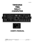
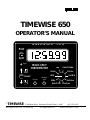
$10.00
TIMEWISE 650
OPERATOR’S MANUAL
TIMEWISE 650
Print
Split
Light
MULTI-SPLIT
CHRONOMETER
Set Sec
RUN
Recall
Printer
Set
TIMEWISE
Select Mode
Silent
Set
©
Lap
Remote
Split
Set Min
10ths
Set Hour
Auto Print
Live/Sync
32 Old Barn Road Hawthorn Woods, Illinois 60047
Part Number 1001–650 revision 2.006
All Rights Reserved
(847) 550-5052
Printed November 1, 2001
WARRANTY
Limitation on Warranty and Liability
Timewise warrants this equipment to be free from defects in material and workmanship for a period of two years from the date of shipment
to the original purchaser. This warranty is limited to the repair and replacement of parts and the necessary labor and services required to
repair the equipment. This warranty is made in lieu of all other expressed or implied warranties, whether written or oral.
Except as specified below, this warranty covers all defects in materials and workmanship. The following are not covered: Damage as a
result of accident, misuse, abuse, or as a result of installation, operation, modification, or service on the equipment; damage resulting from
failure to follow instructions contained in the User’s Manual; damage resulting from the performance of repairs by someone not authorized
by Timewise; damage caused by direct exposure to liquids, solvents, salty air, or corrosive gases; damage caused by exposure to excessive
amounts of dust or dirt; damage caused by exposure to temperatures above or below the storage or operating limits of the equipment; or
normal wear of the instrument enclosure, connectors, or cables.
While under warranty, Timewise will service, repair, replace, or adjust any defective part or parts free of charge, when the instrument is
returned freight prepaid to Timewise. The purchaser is responsible for insuring any equipment returned, and assumes the risk of loss during
shipment.
Limitation of Implied Warranties and Exclusion of Certain Damages
All implied warranties, including warranties of merchantability and fitness for a particular purpose, are limited in duration to the length of
this warranty.
In no event will Timewise be liable to the purchaser or any user for any damages, including any incidental or consequential damages,
expenses, lost profits, lost savings, or other damages arising out of the use or inability to use this equipment. This exclusion includes
damages that result from any defect in the firmware or manual.
How to Obtain Repair Service
If your Timewise equipment requires service, return it to Timewise directly. Do not return it to your dealer. Include a detailed description of
the problem. Timewise must be able to verify the problem in order to repair it. Please include telephone numbers at which you can be
reached during the day and evening.
Equipment to be repaired must be returned freight prepaid to Timewise. All equipment must be packaged with sufficient protection against
shipping damage. You are responsible for transportation charges when returning equipment to Timewise. Insuring the shipment is
recommended. Warranty repairs will be returned via UPS ground freight prepaid. Non-warranty repairs will be returned via UPS ground
COD (repair charges, freight, and COD collection fee), cash only, unless prior arrangements have been made. Alternate shipping methods
can, or will, be used as necessary to assure a prompt and safe delivery.
Repairs on equipment beyond the effective date of warranty or when abnormal usage has occurred will be charged at applicable rates.
Timewise will submit an estimate for such charges before commencing repair, if so requested.
About this Manual and the Operating Firmware of Timewise Equipment
The layout of this manual and the operating procedures for Timewise equipment are trademarks of Timewise. No part of this manual or the
operating firmware for Timewise equipment may be copied or reproduced, in whole or in part, without written consent from Timewise. The
duplication, disassembly or dumping of operating firmware is expressly prohibited.
Disclaimer
Although every effort has been made to make this User’s Manual technically accurate, Timewise assumes no responsibility for any errors,
omissions, inconsistencies, or misprints within this document.
For Further Information
Please feel free to contact Timewise should you have any comments about this equipment. We encourage suggestions for product
improvements. Special applications or customization of Timewise equipment to individual needs will also be entertained.
TIMEWISE
32 Old Barn Road
Hawthorn Woods, Illinois 60047 USA
(847) 550-5052
TIMEWISE 650
Users Manual 1001–650 revision 2.006
Printed November 1, 2001
1
FIRMWARE VERSION HISTORY
650 Operating Firmware History
Version 1.000
First unit delivered.
July 6, 2001
Version 1.001
July 13, 2001
Corrected display of oscillator offset visible when viewing firmware version. Corrected
amount applied when the oscillator was too fast.
Version 1.002
July 18, 2001
Added ability to automatically show the most recent split when executing a remote split
while Live/Sync is selected on the rotary switch. Also added the ability to disable the buzzer
when a remote split is executed.
Version 1.003
July 24, 2001
Added an automatic, once per ten seconds, LCD driver re-initialization. This was to make
certain that the LCD display correctly “wakes up” after the 650 exits the sleep mode.
Rearranged data collection steps to eliminate the possibility that a lap split might display a
value that was incorrect by 0.001 minute. (The problem could have occurred only when a
split was executed within a 30 µsec window exactly 96 msec after a clock update, and only
while the 650 was running in “hundredths”.)
Version 1.004
August 2, 2001
Improved auto-synchronization time alignment to be within 3 milliseconds.
Version 1.005
August 10, 2001
Previously, actuating the Recall “newer” toggle function always caused the live lap timer to
be shown when the Lap rotary switch position was subsequently selected. This recall of live
lap data occurred regardless of the rotary switch position. Now, the Lap rotary switch
position must be selected in order for the live lap data to be recalled.
Version 1.006
August 26, 2001
Added a selectable “restricted datalog access” mode of operation.
Version 2.006
October 15, 2001
Changed the crystal frequency to 307.2KHz.
2
TIMEWISE 650
TIMEWISE 650
THANK YOU…
for choosing the Timewise 650 Multi-Split Chronometer! Your
Timewise 650 is an accurate and versatile multiple split checkpoint
clock that will give years of dependable service. If you’ve used
traditional rally checkpoint clocks, you’ll really appreciate the
improved quality, mistake proof operation, and simplified time setting
procedures provided by the Timewise 650.
How to Use
this Manual
For a brief description of what the 650 does, read the Introduction.
The section covering the Operation of the 650 will teach you how to
use the instrument. Clock setting procedures, the master/slave autosetting procedure, the remote split input connection, and battery
conserving techniques are described there.
Please read the Maintenance & Troubleshooting section. Some
“do’s” and “don’t’s” on the handling of the 650 are discussed there.
Lastly, a technical Specification list is provided.
TIMEWISE 650
3
TABLE OF CONTENTS
TABLE OF CONTENTS
1
2
3
WARRANTY & REPAIR
FIRMWARE VERSION HISTORY
THANK YOU…
How to Use this Manual
4
5
6
7
TABLE OF CONTENTS
TIMEWISE 650 FEATURES
INTRODUCTION
OPERATING THE TIMEWISE 650
The Rotary Switch
Splitting the Clock
Executing Multiple Splits
The Auto Print Rotary Switch Function
Displaying “Tenths” Resolution
Temporarily Viewing the Live Clock
Executing a Lap Split
Deactivating the Buzzer
Putting the 650 to Sleep
Setting the Clock
Changing the Clock Counting Mode
Synchronizing the Clock
Automatic Master/Slave Synchronizing
Clearing the Datalog
Re-initializing the LCD Display
Identifying Recalled Split Data
Lighting the Display
Conserving the Batteries
The Remote Split Input
21
MAINTENANCE & TROUBLESHOOTING
Firmware Version
Replacing Batteries
Preventing Problems
Overheating
Electrical Troubleshooting
Cleaning the 650
Oscillator Adjustment
24
25
4
APPENDIX A - Restricting Datalog Access
SPECIFICATIONS
TIMEWISE 650
FEATURES
TIMEWISE 650 FEATURES
◆ Twelve hour time of day clock accurate to one second over 24 hours
◆ Fifty register memory for multiple splits
◆ Independent lap split timer with tenths of units resolution and
simultaneous time of day split
◆ 0.5" tall, extended temperature, high humidity tolerant, 6 digit LCD
◆ LCD backlight for nighttime use
◆ Secure, yet simple, clock setting procedure
◆ Clock can be set to any hour, minute, or second/hundredth of minute
◆ Seconds/hundredths clock selection at any time
◆ Clock re-adjustments at any time
◆ Fractional seconds/hundredths synchronization at any time
◆ Master/Slave procedure for synchronizing several clocks at any time
◆ Goofproof design …no on-off switch!
◆ Battery saving, automatic shut-down when not used for 24 hours
◆ Remote Split input with intelligent debounce circuitry
◆ Selectable audible buzzer when Split or Remote Split activated
◆ Selectable “restricted datalog access” mode
◆ Tenths of units (59:59.9 or 59.999) resolution at any time
◆ Optional RS-232C interface for sending data to a printer or computer
◆ Optional 9 volt DC input jack for continuous LCD backlighting
TIMEWISE 650
5
INTRODUCTION
INTRODUCTION
The Timewise 650 provides rallymasters, rallyists, and checkpoint workers with an accurate
and easy to read digital time of day clock. The time of day is shown on a 6 digit, 0.5" tall
character, extended temperature range, high humidity tolerant LCD that assures easy
readability, even in direct sunlight. A quartz crystal oscillator accurately maintains the time
to within one second over 24 hours.
The 650 uses a microcomputer designed for applications where ultra-low power consumption
and a wide operating voltage play a significant role in product specification and selection.
Large scale integrated CMOS technology keeps component count and power dissipation to a
minimum, while simultaneously providing increased reliability.
Toggle switches give positive tactile feedback. Placing the switches on the left side frees the
right hand to record data. A rotary switch is used to select the operating mode.
Time of day is displayed in the standard six digit format of hours, minutes, and seconds
(12:59:59). Alternatively, the 650 can display hours, minutes, and hundredths of a minute
(12:59.99). The 650 can also show time resolved to tenths of a second (59:59.9) or
thousandths of minutes (59.999).
The clock can be set to any hour, minute, or second (hundredths of a minute). The clock can
adjusted at any time…even by fractions of a second…up or down! You can switch between
counting in seconds or hundredths of minutes at any time. To prevent accidental loss of time,
there is no “on-off” switch. A simple, but secure, clock setting procedure is used.
The 650 can “split” the current time as a rally car enters a checkpoint. Effectively, the clock
is visually frozen, while continuing to count internally. The 650 can store up to 50 split times
in memory. You can review logged split times forward or backward in time. You can recall
each stored value, again, after having previously observed it.
A “lap split” timer is also provided. When viewing the lap timer, activation of the split switch
displays the frozen elapsed time from the previous lap split action. The lap timer is
simultaneously restarted internally. A time of day split value (separate from the regular split
time of day memory log) is also linked to the lap split time, allowing notation of the time of
day at which the lap split was executed.
A buzzer that signals activation of each split action can be enabled or disabled.
A remote split input is provided for use with optical or pneumatic switches that signal when a
vehicle passes. The buzzer can also sound whenever a remote split input is activated.
One Timewise 650 can automatically set the time in another 650 simply by interconnecting a
common stereo audio cable. This “master/slave” clock setting procedure can take place at
any time. The slave will be synchronized to within three milliseconds of the master.
For nighttime use, the display can be momentarily illuminated with an internal LED light
source. An optional 9 volt input for continuous lighting is available.
Finally, an optional RS-232C interface is available for sending data to a printer or computer.
6
TIMEWISE 650
OPERATION
OPERATING THE
TIMEWISE 650
There is no “on-off” switch for the Timewise 650. If the time is not visible in the display,
actuate any of the toggle switch functions. This will bring the clock out of its battery-saving,
power-down mode.
If the 650 has been used within the last 24 hours, the clock time will still be correct. In such a
case, you may begin using the 650 immediately. (If the time is not correct, you may, if you
wish, go to the section on “Setting the Clock” (page 11) and set the clock now.)
The Rotary
Switch
The 650 uses a rotary switch to select among the functions available in the
clock. Each function will be described as necessary throughout this manual.
WARNING!
The rotary switch has a rotational stop between the Lap switch position and
the Select Mode switch position. Do not force the switch to turn past this
built-in stop! You will break the switch!
The 650 is most often operated with RUN selected on the rotary switch.
Splitting the
Clock
When the Split toggle switch position is actuated, the time of day is
visually frozen. Although it is not apparent, the 650 continues to keep track
of the passage of time internally. That is, the clock does not stop…you just
can’t see the clock count advancing. This is called a “split”.
After you briefly push the Recall toggle switch “upward”, the 650 will once
again display the current “live” time. It will be as if you had never entered
the split mode at all. (While Recall is actuated, some special numbers will
be visible in the display. See “ Identifying Recalled Split Data ” (page 14)
for a full explanation.)
When the 650 is split, the decimal points and/or colons between the digits
will blink on and off each second.
Important note: Generally, you may have the rotary switch in any position
when a split is executed. (Most rallyists select the RUN position for normal
operation.) There is, however, an important exception if you want to use the
full multiple split functionality of the 650. See “Executing a Lap Split”
(page 9) for more information.
Also note: The Live/Sync rotary switch position automatically causes the
650 to display “live” clock data, even if the clock had been split.
Nonetheless, even with Live/Sync selected on the rotary switch, the 650
will execute a split. You must, however, turn the rotary switch away from
the Live/Sync position to see the split data. More on this in a moment.
TIMEWISE 650
7
OPERATION
Executing
Multiple Splits
If you execute a split, again, before recalling the live clock, the 650 will
save the new split time internally in a “multi-split datalog”. Pushing the
Recall switch “up” will retrieve the split time from the second split.
Pushing the Recall switch “up” again will bring back the live clock.
You may execute fifty splits before the 650 memory is full. Each activation
of the Recall switch upward will display the split times in the order they
were saved, with “newer” data being recalled each time the switch is
activated. After all split times have been recalled, the clock will become
live again. You can hold the Recall switch in position to rapidly move
forward in memory through the logged data.
Note: See
Appendix A for
information on
enabling a
“Restricted
Datalog Access”
Mode
If you actuate the Recall switch downward, “older” split memory data can
once again be viewed. The logged data will be recalled in reverse order,
newer to older.
You can cycle through the memory at any time. And note that you can
actuate the Split switch at any time, regardless of which stored split data
you are viewing. The new split data will always be appended to the
memory as the newest split time.
When you have actuated the Split switch more than 50 times, the oldest
split data is discarded as the newest split value is inserted into the memory.
The 650 always has the 50 most recent splits in memory. (You can clear the
entire datalog of all splits with a procedure described later.)
The Auto Print
Rotary Switch
Function
Note that if you are viewing any one of the prior split times (that is, you’re
not looking at the “live” clock), activating the Split switch simply stores
the new value in memory. You won’t automatically see the new split time.
To view that new split, you must actuate the Recall switch (maybe more
than once) to locate the newest split data.
As a convenience, the Auto Print rotary switch function can be used to
eliminate the extra step of executing a recall in order to view each split.
When a split is executed while Auto Print is selected on the rotary switch,
the 650 will automatically bring to the display the new split time. The 650,
in effect, simply executes the needed “recall newest” action for you.
Note that the Recall switch is fully functional even when Auto Print is
selected on the rotary switch. Yet, regardless of what split time you are
reviewing in the datalog when a new split is executed, the 650 will
automatically show the new split time.
By the way, when the 650 is outfitted with an optional RS-232C interface,
executing a split when Auto Print is selected on the rotary position will
cause the 650 to automatically transmit the new split data to a printer or
computer. The optional RS-232C interface and connector must be installed
by Timewise. When the RS-232C option is installed, a special appendix is
included with this manual.
8
TIMEWISE 650
OPERATION
Displaying
“Tenths”
Resolution
Normally, the time of day is resolved to six digits: 12:59:59 when in the
“seconds” mode of operation, or 12:59.99 when operating in the
“hundredths of minutes” mode. (Choosing the “seconds” or “hundredths
of minutes” mode of operation will be described later.)
When the “10ths” rotary switch position is selected, the clock is visually
shifted left to reveal an extra digit of resolution. (The hours will no longer
be visible.)
This allows you to record “tenths of seconds”, or “thousandths of minutes”
split times. You can select the “10ths” rotary switch position whenever
this information is needed, either before or after the clock has been split.
Temporarily
Viewing the
Live Clock
The Live/Sync rotary switch position causes the 650 to display the live
clock, even when the clock is split. If you are viewing a split value, and
wish to momentarily see the live clock, simply turn the rotary switch to
Live/Sync. When Live/Sync is de-selected, the previously viewed split
time is once again displayed.
The 650 will execute a split even with Live/Sync selected on the rotary
switch. However, you must eventually leave the Live/Sync position to see
the split data. (Note that when Live/Sync is selected, the Recall toggle
switch will not scan through the datalog memory.)
If you actuate a remote split (details later) while Live/Sync is selected on
the rotary switch, the live clock itself will be temporarily replaced by the
new split time that is being saved in memory. This “latest split” will remain
visible as long as the remote split switch is actuated. (This is a feature used
by some rallyists running stock class. They depress and hold a remote
switch to split the clock. The time of day will be visibly split until they
release the switch, whereby the display immediately becomes live again.)
Executing a
Lap Split
A “lap” timer is also provided in the 650. Turn the rotary switch to the Lap
position to view the lap timer.
The lap timer can be used to measure the individual duration of consecutive
events. Such would be the case when measuring the time it takes to drive
successive tenth mile sections on a course, or consecutive laps on a race
track. (By the way, a lap split is often called a “Taylor split” in reference to
Frederick Winslow Taylor who pioneered work-time studies at the turn of
the twentieth century.)
The lap timer counts from 00:00.0 to 59:59.9 (minutes:seconds.tenths)
when operating in “seconds”, or 00.000 to 59.999 (minutes:thousandths of
minutes) when operating in “hundredths of minutes”.
When viewing the lap timer, actuation of the split switch causes the 650 to
display the frozen elapsed time since the previous lap split action. The 650
then automatically resets the lap timer internally. When you execute
another lap split, you will be presented with a new elapsed time.
TIMEWISE 650
9
OPERATION
The lap split timer is independent of the clock. When you execute a lap
split, the 650 does not store a split time of day in the normal memory
datalog. Nonetheless, a split time of day value is saved for display purposes
only. This data is visible when the Print toggle switch is actuated while
Lap is selected on the rotary switch.
(Should a control worker mistakenly have the Lap position selected when a
vehicle enters a checkpoint, the linked time of day split for the lap split can
be used as the arrival time.)
After executing a lap split, you may turn the rotary switch away from the
Lap position, and back again. The latest lap split value will once again be
displayed. The split time of day for the lap split (visible when the Print
toggle switch is selected) can also be reviewed again.
Only one lap split time (and the associated time of day for the lap split) is
stored in the 650. Upon each lap split execution, the 650 automatically
shows the new lap split time…the previous lap split data is discarded.
You can look at the “live” lap timer (for the current lap) by pushing the
Recall toggle switch up when Lap is selected. Pulling the Recall toggle
switch down retrieves the last lap split time. (When Lap is selected, the
Recall toggle switch does not scan through the normal datalog memory.)
Deactivating
the Buzzer
Normally, whenever a split is actuated (via the front panel Split switch or
the Remote Split input), a buzzer will briefly sound.
If the buzzer is not desired, select the Silent position on the rotary switch.
When a front panel split is executed with Silent selected, the 650 enters a
silent mode of operation. The buzzer will no longer sound, regardless of
which rotary switch position is selected…until you split (via the front panel
Split switch) the 650 with the RUN position selected. At that time, the
buzzer will sound again in all rotary switch positions. If you once again
execute a split with the rotary switch turned to the Silent position, the 650
will again be silent.
Putting the 650
to Sleep
The 650 will automatically turn off its display if no toggle switch is
actuated for eight hours. After the display blanks, actuate any toggle to
once again see the clock. The time will be correct and the datalog will be
intact. However, if no toggle switch is used for 24 hours, the 650 shuts
down completely. All logged data will then be lost and the time of day will
have to be set again.
You can speed up the complete shut down of the 650, if you wish. To do
so, first bring to the display the “live” clock. Then turn the rotary switch to
the Silent position. Lastly, select Print. The 650 will immediately blank the
display. When the display is turned off in this manner, the clock will
continue to run internally for only six more hours before completely
shutting down. Activating any toggle switch before six hours pass will turn
the display on. The normal 24 hour shut down wait period is then restarted.
10
TIMEWISE 650
OPERATION
Setting
the Clock
Setting the clock in the 650 is simple and direct. The procedure is,
nonetheless, nearly impossible to execute accidentally, thus reducing the
possibility that a control worker inadvertently alters the time of day.
Notice the clock “set” icons next to the Recall switch. These icons signify
that, when setting the clock, the Recall switch will adjust the clock’s digits
forward or backward: pushing the Recall toggle upward advances the
clock; pulling the toggle actuator down causes the clock to go backward.
To set the clock in the 650, start by turning the rotary switch to RUN. Then,
at a noted time of day, actuate and hold the Split switch. While holding the
Split toggle actuator down, turn the rotary switch to one of the clock setting
positions: Set Sec , Set Min, or Set Hour. Then release the Split switch.
(The Select Mode and Live/Sync rotary switch positions are also clock
setting positions. But for now, don’t select them.)
Now, using the Recall switch, adjust the clock to the time of day at which
you initially depressed the Split switch. Select among the Set Sec, Set
Min, and Set Hour positions as needed. If you hold the Recall actuator in
the up or down position, the selected unit will be continuously adjusted.
After setting the clock, turn the rotary switch to RUN (or at least as far as
the Auto Print position) to exit the clock setting mode.
To restate, here’s the step by step method for setting the clock:
1.
2.
3.
4.
5.
Turn the rotary switch to RUN.
Noting the time of day, actuate (and hold) Split.
Turn the rotary switch to Set Sec, Set Min, or Set Hour.
Release the Split switch.
Use the Recall switch to set the clock to the time noted in step 2.
Select among Set Sec, Set Min, and Set Hour positions as required.
6. When finished, return the rotary switch to RUN.
The current time of day will now be displayed. If your reaction time was
slow when you initially depressed the Split switch, the clock may be off by
a count. If so, re-enter the clock set mode and correct the clock as needed.
(As a convenience, when setting the clock, the up and down positions of the
Split/Print switch may also be used to set the clock. Normal functionality
of the Split/Print switch is disabled while the clock setting mode is active.)
You may take as much time as needed while setting the clock. This is
because the 650 adjusts the internal live clock by the same amount that you
adjust the displayed split value. Upon exiting the clock set mode, the live
clock will have been adjusted by the correct amount, regardless of how
long you spent executing the procedure.
IMPORTANT!
Setting the time of day clears all logged data in the 650 memory.
TIMEWISE 650
11
OPERATION
Changing the
Clock Counting
Mode
The clock may be run in either “seconds” (11:59:59); or “hundredths of
minutes” (11:59.99). Notice the decimal point instead of a colon after the
minutes when operating in the “hundredths of minutes” mode.
To change between “seconds” and “hundredths”, enter the clock setting
mode as described previously, this time choosing Select Mode on the
rotary switch. (That is, select RUN, actuate (and hold) Split, turn the rotary
switch to Select Mode, then release Split. If you were already in the clock
setting mode, simply turn the rotary switch to Select Mode.)
Now actuate the Recall switch (up or down). Each time you do so, the 650
will toggle between the two counting modes. You may change modes at
any time. (You can also use the Split/Print switch to change modes.)
After changing the clock counting mode, turn the rotary switch to RUN (or
at least as far as the Auto Print position) to return to normal operation.
One benefit of being able to change the counting mode of the clock is
evident when setting the clock at the beginning of the rally. You can use the
“seconds” mode while aligning to WWV or another broadcasted time
standard, and then switch to “hundredths” to run the rally.
Note: You can alternate between counting modes without clearing the log
memory. This is possible if you enter the clock setting mode, only change
counting modes, and then leave the clock setting mode. You may,
therefore, collect several split times while in “seconds” and read them back
in “hundredths” providing you don’t actually change the time of day.
Synchronizing
the Clock
Setting the clock does not alter the beat of the clock. That is, the “ticking”
pulse of the clock is not changed. If the clock is “out of sync” with the
official time standard, you should synchronize the 650 to the time standard.
To do so, activate the clock setting mode as before, this time selecting the
Live/Sync rotary position. When you select this clock setting function, the
clock will be live again. Now use the Recall switch (or Split/Print switch)
to make the clock run slightly fast (move the toggle actuator handle up), or
slow (move the toggle handle down). Repeat as necessary until the clock is
synchronized to the time standard. (If you hold the actuator in position, the
clock will be adjusted continuously.)
After you are satisfied that the clock is synchronized to the time standard,
double check the “seconds” digit of the clock against the time standard.
While synchronizing, you may have sped the clock up or slowed it down by
a full count. Should you need to correct the “seconds”, turn the rotary
switch to the Set Hour clock setting position. At the moment you de-select
the Live/Sync position, the clock will be split again (at the time that was
being displayed as you de-selected Live/Sync). If necessary, correct the
seconds after turning the rotary switch to the Set Sec position.
After synchronizing the clock, turn the rotary switch to RUN (or at least as
far as the Auto Print position) to return to normal operation.
12
TIMEWISE 650
OPERATION
Automatic
Master/Slave
Synchronizing
A Timewise 650 can automatically set the time in another 650 using a
master/slave communication protocol built into the instruments. That is, a
650 previously aligned to the official time, can insert that time into another
650. The automatic synchronizing procedure takes about two seconds and
may be performed at any time.
To execute the synchronizing procedure, you will need a synchronizing
cable to interconnect two 650’s. A standard stereo audio cable is used for
this purpose. Such a cable is readily available from Radio Shack as part
number 42-2387. This 6-foot stereo audio cable (two wire plus shield) has
the required 1/8 th inch stereo miniature phone plugs at each end. (You may,
of course, fashion your own synchronizing cable using 1/8th inch stereo
plugs and three wire cable. To do so, just connect the three contacts of the
plugs straight through. Keep the cable shorter than 7 ft.)
To synchronize two 650s, turn the rotary switch on the master 650 (the
unit with the official time) to RUN, and the rotary switch on the slave to
Live/Sync. Then plug the synchronizing cable into each unit’s
Remote Split input jack. Finally, actuate Recall (up or down) on the slave.
The display on the slave will go blank after a moment. When the display
comes back on, the slave 650 will be set to the exact time as the master
650. The counting mode of the master (“seconds” or “hundredths of
minutes”) will also be set in the slave.
You’ll note that as you insert the synchronizing cable into each unit’s
Remote Split input, the contacts in the socket may temporarily short
together, causing either or both 650 to split. This will not interfere with the
synchronizing procedure. You can, if you wish, “unsplit” the master before
synchronizing. Removing the cable also usually splits the clocks.
Take care not to shuffle the master and slave. You don’t want to set the
time in the master to that of the slave!
This automatic clock synchronization procedure also works in conjunction
with the earlier Timewise 610 Multi-Split Checkpoint Clock. Either the 610
or the 650 may be a master or slave. The 650 can also be the master source
of time for Timewise 547B and 798A rally computers.
Clearing the
Datalog
As mentioned, the datalog memory is cleared of all split times whenever
the clock is set. This is done so that there is never a question as to the
validity of the split times in the memory.
The datalog memory can also be cleared without setting the clock. To do
so, simultaneously select both the Print toggle position and the Recall
toggle switch “down” position. All logged data will be discarded.
Re-initializing
the LCD Display
When you clear the datalog, the LCD display driver is also re-initialized. If
the LCD display does not work correctly when the 650 exits the sleep
mode, clearing the datalog will fix the display.
TIMEWISE 650
13
OPERATION
Identifying
Recalled
Split Data
When the Print toggle is actuated, the display will show two numbers. Use
these numbers to help ascertain the order of the data in the 650’s memory.
The number on the left indicates the number of split actions that the
currently viewed data is removed from (or “away from”) the live clock. It
tells you, in a sense, how many “splits ago” the data was collected. Use this
number to find the split time “for the car that arrived at the checkpoint
three splits ago.” The “splits ago” number can range from 0 to 50.
(Remember: The 650 can hold a maximum of 50 splits in memory.)
The number on the right is the sequence number of the split [since the log
was cleared]. Read the value as an ordinal number (e.g., first, second, third,
etc.). Use this value to identify, for example, “the split time for the fifteenth
car that entered the control.” The sequence number ranges from 1 to 999.
50 999
“splits ago”
“sequence”
(splits away from (first car, second
live clock)
car, third car, etc.)
The “splits ago” and “sequence” numbers will be continuously shown
while Print is actuated. The numbers are also briefly shown whenever the
Recall toggle switch is actuated. If you hold the Recall switch in place, the
650 cycles through the datalog memory, incrementing and decrementing
the “splits ago” and “sequence” numbers appropriately.
Here are some examples that help explain the meaning of these numbers.
Let’s assume that the 650 is showing the live clock, and that the datalog
memory has been cleared of all split times. The following information will
be shown when Print is selected. (If you want to follow along with your
650, start by clearing the datalog as previously described.)
0
“splits ago”
–––
“sequence”
The clock is live, so the “splits ago” number is “0”. The “sequence”
number is blank because you are not looking at split data.
14
TIMEWISE 650
OPERATION
Execute a split, simulating the arrival of the first vehicle. Then select Print.
The display will show:
1
“splits ago”
1
“sequence”
The “splits ago” value is now “1” because that is how far the data is
removed from the live clock. The sequence is also “1” because the data is
for the first car.
Now split again (before recalling the live clock), simulating the arrival of
the second car. Actuate the Print toggle function and you will see:
2
“splits ago”
1
“sequence”
The “splits ago” count has increased to “ 2”. The displayed split data is
unchanged, but it was collected “two splits ago”. The sequence number
remains at “1” because the split data is still the log entry sequence number
for the first car.
Read the display as, “The data was collected two splits ago, and it was for
the first car.”
After ten more splits (assuming you haven’t activated the Recall switch —
this checkpoint is busy!), the display will show (when Print is actuated):
12
1
The “splits ago” is now “12”. The data being viewed (for the first car) is
now twelve splits removed from the live clock. The split sequence remains
at “1” because that is still (and will forever remain) the log sequence
number for the first car.
Read the display as, “The data was collected twelve splits ago, and it was
for the first car.”
TIMEWISE 650
15
OPERATION
Let’s assume you now have time to recall the split data from the other
vehicles. Actuate the Recall toggle switch “up” once, select Print, and
you’ll see:
11
2
Read the display as, “The data was collected eleven splits ago, and it was
for the second car.”
You are looking at the split executed upon arrival of the second car, and
that split occurred eleven splits ago.
(As you probably observed, the “splits ago” and “sequence” numbers were
momentarily displayed, for about a half second, when you actuated Recall.)
Now proceed to recall the data from subsequent vehicles. When you reach
the data for the most recent vehicle, actuate Print to show:
1
12
The “splits ago” is now “ 1”. The data was collected one split ago, and it
was for the twelfth car.
(Note that whenever the “splits ago” is a “1”, you are viewing data for the
last car that entered the checkpoint. You will be only one split removed
from the live clock.)
Now assume another car arrives before you recall the live clock. You
execute a split, then actuate Print. The display shows:
2
12
The “splits ago” count has become a “2”, because a new split time was
entered into the datalog. You are, however, still looking at the data for the
twelfth vehicle. The split “sequence” remains at “12”
Thus, the currently viewed data was collected two splits ago, and it was for
the twelfth car.
16
TIMEWISE 650
OPERATION
Push Recall up once to recall the split time for the thirteenth car. Selecting
Print will show:
1
13
You are once again one split removed from the live clock The data is now
from the thirteenth car.
Actuate Recall up one more time, select Print, and the display shows:
0
–––
The “splits ago” is “0” once again because you’re looking at the live clock.
The split sequence is blank because you are not looking at split data.
At this point, the rallymaster arrives and wants to see the arrival time for
the second most recent vehicle. Actuate Recall down twice, and you will
see the split time for the vehicle that arrived two splits ago. When Print is
selected, the display shows:
2
12
The viewed data was collected two splits ago, and it was for the twelfth car.
If you repeatedly actuate Recall down (or just hold the switch down) the
“splits ago” and “sequence” will increment and decrement, respectively,
until you reach the data for the first car that entered the checkpoint:
13
1
The “split ago” count is “13”. You are looking at data that was collected
thirteen splits ago, and it was for the first vehicle.
Push Recall up as needed to return to the live clock:
0
TIMEWISE 650
–––
17
OPERATION
As time goes on, more vehicles arrive at the checkpoint. As each vehicle
crosses the in-line, you note each split time and immediately recall the live
clock. If you actuate Print after each recall, the display will show the “live
clock info” every time:
0
–––
When the 73rd car enters the control, you split as before, but actuate Print
before recalling the live clock. The display will show:
1
73
You are looking at data collected one split ago, and it was for the seventythird car that entered the checkpoint.
Now, remember that the 650 retains in its memory the data for the 50 most
recent splits.
Consequently, if you repeatedly actuate the Recall toggle switch “down”,
to review older and older data, you will eventually reach the oldest split
data in memory – the data from 50 splits ago. At this point, the Recall
down action has no older data to recall. Selecting Print will show the
following:
50
24
The split data you are viewing (the oldest data in memory) was collected
fifty splits ago, and it was for the twenty-fourth car.
You can no longer recall older split data — i.e., data from the first through
the twenty-third vehicles — as that data has been purged from memory.
The 650 retains data only as far back as 50 splits ago.
Should the checkpoint now close, the split data from the twenty-fourth
through the seventy-third vehicles (the last 50 vehicles that entered the
checkpoint) will be retained in memory.
18
TIMEWISE 650
OPERATION
Lighting the
Display
The LCD display on the 650 may be illuminated with a soft, yellow-green
“backlight” by depressing the small pushbutton located between the toggle
switches. The LCD lighting is only visible in low ambient light conditions.
The light remains on as long as you depress the pushbutton.
As an option, the 650 can be outfitted with hardware that allows continuous
LCD backlighting. The option requires an external 9 volt DC power source
to power the light. When the option is present, there will be an input power
receptacle accessible on the right side of the 650. The receptacle mates to a
“coaxial DC power plug”. The input receptacle requires a plug that is
5.0mm diameter on the outside, and has a 2.1mm diameter hole.
A suitable 9 volt DC power source is available from Radio Shack. Their
part number 270-1562 is a DC voltage converter that plugs into a cigarette
lighter. This power converter comes with a selection of coaxial plugs, one
of which fits the receptacle on the side of the 650. Install the plug so that
the center contact (i.e., the tip) is the “+” polarity of the voltage.
WARNING! DO NOT use the 12 volt output setting on the voltage
converter. The voltage provided in that setting is not a regulated 12 volts.
Instead, the converter simply passes the unregulated vehicle voltage to the
output. Since the vehicle’s alternator circuitry produces about 13.8 volts
while charging the battery, the converter will output 13.8 volts when the car
is running. Note, too, that a fully charged battery will initially provide
about 13.2 volts. Damage to the 650 will occur when more than 12
volts is continuously applied to the backlighting circuitry .
Conserving the
Batteries
As mentioned earlier, the 650 will automatically turn off its display if no
toggle switch is used for eight hours. After the display blanks, actuate any
toggle to make the clock visible once again. The time will be correct.
If no toggle switch is used for 24 hours, the 650 shuts down completely.
You can hasten the complete shut down of the 650, if you wish. To do so,
select the Silent rotary switch position, make the clock live, and then
actuate Print. The 650 will immediately blank the display. When the
display is turned off in this manner, the clock will run for only six more
hours before completely shutting down. Activating Print, again, (or any
other toggle position) before the six hours pass will turn the back display
on. The normal 24 hour shut down wait period is then restarted.
NOTE:
By leaving the rotary switch in the Silent position, the 650 consumes less
energy (about 15 µamps less current) while it is shut down. This can extend
battery life an additional 2 months during storage.
NOTE:
Also, note that for every five seconds the LCD backlighting pushbutton is
depressed, the batteries are drained the equivalent of one hour or more of
normal operation. If you use the backlighting a lot, the batteries will have
to be replaced more often. If you cannot see the LCD backlighting in the
dark, it is time to replace the batteries. (The 650 will run about 10 days on
batteries that can no longer power the LCD backlighting.)
➠➠
TIMEWISE 650
19
OPERATION
The Remote
Split Input
The Remote Split input provides a means of splitting the 650 via an
external switch closure. The remote split connector accepts an 1/8 th inch
miniature stereo phone plug. Contact assignments for the connector are:
Shaft— Ground; connected to the negative side of the 6 volt supply.
Ring — Remote split input; held high (to 5.3 volts) with a 3KΩ pullup resistor and connected to a CMOS input via a 1KΩ series
resistor. The input must be brought to 0.5 volt or less for a
remote split to be sensed and returned to 5 volts to reset the
sensing circuitry. After receiving a remote split, the 650 waits
at least 0.6 second before another split can be sensed.
Tip — Clock synchronization data in/out; held high (to 5.0 volts)
with a 100KΩ pull-up resistor and connected to a CMOS
gate via a 1KΩ series resistor. Synchronization data is
transmitted once every two seconds when RUN is selected on
the rotary switch; data is accepted when Recall is actuated
while Live/Sync is selected on the rotary switch.
Do not apply any voltage to any of the contacts!
To activate the Remote Split function, all you need to do is make an
electrical connection between the ring and shaft contacts of the input
connector. Here’s what you need to build an appropriate plug/cable/switch
assembly. Radio Shack is a good source for all these items:
1.
2.
3.
4.
Miniature stereo phone plug (three contact; 1/8th inch diameter)
Two conductor cable (shielded cable is fine, but not required)
A single pole, normally open switch.
The correct tools and materials for cutting, stripping, and
soldering wires to the switch and plug.
The cable assembly is easy to make: At one end of the cable, solder one
conductor each to the “ring” and “shaft” contacts of the miniature phone
plug. (The ring is the middle contact visible on the plug; the shaft is the
contact nearest the handle.) At the other end of the cable, solder one
conductor to each of the switch contacts. (With shielded cable, solder the
shield drain wire to the shaft contact on the plug.)
(Note that the “tip” contact in the socket is the data pathway for the
automatic clock synchronizing procedure. Don’t connect the external
remote switch to that contact.)
Once assembled, plug the cable into the Remote Split input on the 650.
Each time the switch contacts close, the 650 will be split.
CAUTION! Do not discharge static electricity into the Remote Split input.
A static discharge into the input will damage the 650.
20
TIMEWISE 650
MAINTENANCE & TROUBLESHOOTING
MAINTENANCE
& TROUBLESHOOTING
Firmware
Version
To identify the operating firmware version that is in your 650, select RUN
on the rotary switch, actuate and hold Split, and turn the rotary switch to
Lap. The display will alternately show the firmware version, and a value
indicating a correction (with a “PUSH” or “ PULL” direction) applied to the
crystal used in your 650 to compensate for manufacturing tolerances.
Replacing
Batteries
The batteries in the Timewise 650 must be replaced once every 5 months.
Use four fresh “AA” alkaline batteries. The batteries are accessible by
opening the 650. To do so, remove the Phillips head screws in the four
corners of the front panel. The case can then be pulled off, revealing the
battery holder. (A piece of foam that cushions the batteries sometimes
sticks to the battery surface - you may have to do a little “wiggling”.)
Check the battery holder contacts for signs of corrosion and carefully clean
as required. When re-installing the four screws, take care not to crossthread them in the case…and don’t overtighten them!
Preventing
Problems
Some components within the instrument are very sensitive to static
electricity. When you open the 650 to replace the batteries, be very careful.
A static discharge to a solder trace on the printed circuit board can damage
the instrument. You can damage the 650 with a static discharge that is a
thousand times weaker than the energy required to form a spark.
Don’t fool yourself about your impunity to static electricity. While riding in
a vehicle, a static charge is generated within the entire vehicle as the tires
flex against the road. Such charges generally dissipate evenly throughout
the vehicle and therefore do not cause a problem. However, fabric used to
cover seats can lead to a localized charge on your body. In some cases, just
touching the knurled nut on the Remote Split input, or the metal wires of a
cable connected to that input, can cause a problem.
If you’ve experienced a problem with static electricity in your vehicle,
Timewise suggests you treat the inside of your vehicle with a static
dissipating chemical. Anti-static treatments, often in an aerosol or pump
spray bottle, are available from stationary and computer stores.
Overheating
The Timewise 650 is designed to operate in the temperature range you
generally experience a vehicle. However, on hot summer days with little
wind blowing, temperatures in a parked closed vehicle can exceed 160˚ F.
In such a case, the 650 will exceed its maximum operating temperature.
Keep the 650 out of direct sunlight when it’s in a closed vehicle. During
lunch breaks or rest stops, locate the 650 in a shaded area inside the
vehicle. However, don’t store the instrument in the glovebox.
TIMEWISE 650
21
MAINTENANCE & TROUBLESHOOTING
Electrical
Troubleshooting
If you experience problems with operation of the Timewise 650, here
are several areas to investigate before concluding that the instrument is
broken.
❏
❏
❏
❏
❏
❏
Cleaning the
650
Is the LCD off because you are in the power saving mode?
Actuate any toggle switch to exit that mode.
Are four “AA” batteries present in the battery holder?
Are the batteries in good condition? Replace them every 5
months, regardless of whether or not the clock runs. Battery
corrosion can damage the 650. All batteries eventually corrode.
A corroded contact can cause an intermittent power disruption.
Are the battery contacts clean? Are the battery holder contacts
clean?
Are the batteries inserted correctly? The holder indicates the
correct orientation.
Are newly inserted batteries fresh or are they just “unused”?
Old batteries can cease to output a voltage, even though they
may never have been used.
Keep the 650 free of as much dirt and grime as possible. Although it is
obviously impossible to prevent accumulation of dust and fingerprints,
ordinary precautions can protect your 650 from excessive dirt.
Be careful when cleaning the front panel. Although the polycarbonate
surface is protected from minor scratches by a protective coating, abrasive
grit and certain cleaning chemicals will mar the panel. To clean the panel,
use a mild plastic cleaning solution or a very weak solution of dishwashing
liquid and water. Do not use chemical solvents, ammonia glass cleaners,
bathroom and kitchen cleansers, or any aromatic hydrocarbon based
cleaner. Use a soft cloth and wipe accumulated dirt off carefully to prevent
scratches.
Never spray a cleaner directly on the 650; rather, spray a cloth and then
clean the panel with the damp cloth. If you spray a cleaner directly on the
front panel, some of the liquid will enter the switches and cause internal
corrosion and eventual failure of the switch mechanism.
WA RN I N G !
Chemicals used in insect repellents may damage the front panel on
the 650. Do not let these chemicals come into contact with the
panel, as you can ruin the appearance of the instrument
22
TIMEWISE 650
MAINTENANCE & TROUBLESHOOTING
Oscillator
Adjustment
The Timewise 650 uses a quartz crystal oscillator to accurately maintain
the time. The oscillator has been corrected to provide a clock accurate to
within ± 1 second after 24 hours.
After a period of time, the crystal and other parts of the circuit age. This is
true for all oscillator circuits. The clock will then gain or lose time to a
greater amount than the specified accuracy. The oscillator should then be
re-adjusted. Although the procedure is simple, the equipment required to
make the adjustment is quite specialized.
Do not attempt to adjust the oscillator unless you have the appropriate test
equipment and are experienced at calibrating electronic instrumentation.
For those of you that qualify, here’s the procedure to follow:
1. Open the 650 by removing the Phillips head screws in the four corners.
Pull off the case.
2. Remove one of the “AA” batteries from the battery holder. This will
disconnect all power from the instrument.
3. Select the Live/Sync rotary switch position.
4. While pushing the Recall toggle switch “up”, re-insert the battery. Wait
about one second and then release the Recall toggle. The 650 will enter
an oscillator adjustment routine. (The clock will not count, and the
display will probably be blank.) A 2560 Hz square wave signal will be
output on the tip contact of the Remote Split jack. Connect this signal
to a frequency counter.
5. Locate a small adjustable capacitor on the back of the printed circuit
board next to the battery holder. (If the adjustable capacitor is absent,
the 650 must be returned to Timewise for adjustment.)
Using a small non-conductive flat-blade adjustment tool inserted into
the adjustable capacitor, change the output calibration signal to
2560.000 Hz, ± .005 Hz. (On most 650s, a different frequency is
written on an adhesive sticker placed on the side of the buzzer. When
such a number is present, adjust the oscillator to that figure instead.)
IMPORTANT! Do not use a metal blade screwdriver for this
adjustment! The capacitance of your body will unpredictably change
the frequency of the oscillator as you make the adjustment.
The capacitor adjustment screw will need to be turned very little. Note
that the screw will turn endlessly, cycling through its adjustment range
with each revolution. If the oscillator cannot be adjusted to the correct
value within one revolution of the adjustment screw, the 650 must be
returned to Timewise for repair.
(As a matter of interest, the 650 will be accurate to ± 1 sec. in 48 hours
if the oscillator is set to 2560.000 Hz, ± .015 Hz.)
6. After making the adjustment, de-select the Live/Sync rotary switch
position. Normal operation of the clock will resume.
TIMEWISE 650
23
Appendix A
Restricted
Datalog Access
Mode
(firmware version
1.006 and newer)
Restricting Datalog Access
If you wish to somewhat simplify operation of the 650, the instrument can
be operated in a special mode that restricts access to the datalog memory.
Restricting access to the datalog can prevent inexperienced checkpoint
workers from casually scanning through the datalog and becoming “lost in
the data”.
When running in the “restricted datalog access” mode, scanning backwards
through the datalog (to review older split data) is only possible when the
Auto Print rotary switch position is selected. Administrative personnel
(e.g., checkpoint captains) can be informed of this simple security override.
To enter the restricted access mode, do the following: display the live clock
by actuating the Recall switch as necessary. Then turn the rotary switch to
the Select Mode position. Finally, hold the Recall switch up continuously
for about 7 seconds. The buzzer will briefly sound, and the “sequence” and
“splits ago” numbers will be replaced by the live clock. The 650 will now
be operating the restricted datalog access mode.
When operating in the restricted access mode, you can retrieve the live
clock following each split, as is usual, using the Recall “newer” toggle
switch position. Also as is usual, if you execute several splits before
recalling the live clock, you can move forward through the split data
recalling each split time in sequence, until the live clock is reached.
However, you can no longer scan through the datalog memory searching
for previously viewed data. That is, you cannot go backwards in the datalog
by using the Recall “older” toggle switch position.
In effect, the 650 will function in the classic data recall method of the
Timewise 610 and Zeron 88 checkpoint clocks.
When operating in the restricted access mode, the “sequence” and “splits
ago” numbers are not shown when the Recall switch is actuated. You can,
however, actuate the Print switch to see the identification numbers for the
current data.
Should it become necessary to review older split data, turn the rotary switch
to the Auto Print position. The Recall “older” toggle switch position will
then be active, and you can scan backwards through the datalog. After
reviewing the data of interest, select any other rotary switch position to
return to the restricted access mode. Note that the “sequence” and “splits
ago” numbers are shown when Auto Print is selected on the rotary switch
and the Recall switch is actuated.
When you no longer want to operate in the restricted datalog access mode,
turn the rotary switch to the Select Mode position, display the live clock,
and hold the Recall switch up continuously for about 7 seconds. The buzzer
will briefly sound when the restricted datalog access mode is exited. The
“sequence” and “splits ago” numbers will become visible at this time.
24
TIMEWISE 650
SPECIFICATIONS
TECHNICAL
SPECIFICATIONS
Design
CPU type:
Operating memory:
Display:
Multi-split storage:
Lap Split storage:
Displayed Time of Day:
Information
Lap Split Data:
Log count:
Clock Accuracy
MC68HC705C8A (or C9A) operating @ 307.2 KHz
Program: 7584 bytes Data: 304 bytes
Extended temperature range, high humidity tolerant, 0.5"
tall character, 6 digit LCD
50 memories (first in - first out), with replay
1 (separate from time-of-day splits, with recall)
12:00:00(.0) to 11:59:59(.9)
or, 12:00.00(0) to 11:59.99(9)
00.000 to 59.999 (or, 00:00.0 to 59:59.9)
“xx yyy”
xx = “split’s ago” count from live (range 0 to 50)
yyy = split “sequence” being viewed (range 1 to 999)
± 1 second in 24 hours (but typically 48 hours)
4 “AA” alkaline batteries
Electrical Power source:
Power requirements: 4 to 6 VDC; 150 to 250 µamps while running; 100 to 200
µamps during standby; 15 µamps while asleep; 50 mamps
max. when the LCD backlight activated
Expected battery life: 3600 hours (5 months) during normal useage (20% “on”
time). Battery life is significantly decreased when the LCD
backlighting is operated – activating the backlighting for 5
seconds consumes the equivalent energy used during 1 hour
of non-lighted operation.)
Optional external power requirements for continuous LCD
backlighting: 9 VDC, 40 mamps; or, 12 VDC, 70 mamps
WARNING: Do not use the unregulated 13.2 volts that is
typical of a fully charged “12 volt” lead acid battery.
Environmental
Physical
Storage temperature:
–40°C to 80°C
Operating temperature: –15°C to 40°C
Humidity:
20% to 90%, non-condensing
Enclosure:
Phenolic
Front panel:
Scratch protected polycarbonate over aluminum
Size:
4.025" x 2.925" x 2.3" (including height of switches)
Weight:
Approximately 11.5 oz. (including batteries)
Optional coaxial DC input jack for continuous backlighting:
5.0mm OD, 2.1mm ID; (+ on pin, – on sleeve)
TIMEWISE 650
25