1
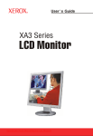
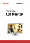
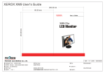
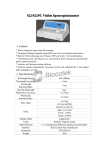
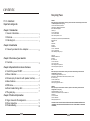
CONTENTS
Recycling Place
F.C.C. statement
Important safeguards
Chapter 1 Introduction
1.1 General Information.......................................... 1
1.2 Features........................................................ 1
1.3 Checking List.................................................. 1
Chapter 2 Installation
2.1 Connect your monitor to a computer...................... 2
Chapter 3 Overview of your monitor
3.1 Controls....................................................... 3
Chapter 4 Operation Direct-Access Features
4.1 Switch the power ON/OFF .................................. 4
4.2 Power indicator............................................... 4
4.3 Volume (only for monitor with speaker function)....... 4
4.4 Menu features................................................. 4
4.5 OSD menu..................................................... 5
4.6 Preset modes timing chart.................................. 7
4.7 Plug and play.................................................. 7
Chapter 5 Technical information
5.1 Signal Connector Pin Assignment.......................... 8
5.2 Visual Inspection. ........................................... 9
5.3 Troubleshooting.............................................. 10
EUROPE
When disposing of Proview Monitors in Europe, please contact one of the following three locations
to make arrangements for recycling.
Proview International (UK) Limited
30 The Avenue, Watford, Hertfordshire
WD17 4AE United Kingdom
Timothy Lo
Tel: +44-1923-248-111
Fax: +44-923-248-222
Email: [email protected]
PGL Europe B.V. (Proview Group Limited Rotterdam)
Satijnbloem 37,
3068 JP
Rotterdam
Hollande
David Hsieh
Tel: +31-10-238-1090
Fax: +31-10-238-1091
Email: [email protected]
Xoal bvba
Raketstraat 100-B1130
Bruessels
Mr. Leo Starckx
Tel: +32-2-702-6011
Fax: +32-2-725-2513
Email: [email protected]
[email protected]
ASIA
When disposing of Proview Monitors in Asia, please contact the following location to make
arrangements for recycling.
Proview Technology (ShenZhen) Co., Ltd.
North Block 21, 23# Shatoukok Free Trade Zone, ShenZhen, China.
Mr. Dennis Chang
Tel: +86-755-2526-1512
Fax: +86-755-2526-1565
Email:[email protected]
AMERICA
When disposing of Proview Monitors in America, please call the following location to make
arrangements for recycling.
Proview Technology, Inc. (U.S.A.)
7373 Hunt Avenue, Garden Grove, CA 92841 U.S.A.
Patrick Yen
Tel:+714-799-3865
Fax:+714-379-6290
Email:[email protected]
THIS DISPLAY UNIT IS AN ELECTRIC DEVICE WHICH MAY CONTAIN HAZARDOUS MATERIALS AND
COMPONENTS, AND WHICH MUST BE DISPOSED OF AT END OF LIFE ACCORDING TO THE PROPER
PROCEDURE
FEDERAL COMMUNICATIONS
COMMISSION(F.C.C) STATEMENT
IMPORTANT SAFEGUARDS
Warnings:
1. Read all of these instructions Save these instructions for later use, please.
This equipment has been tested and found to comply with the limits of a
Class B digital device,pursuant to Part 15 of the FCC Rules. These limits are
designed to provide reasonable protection against harmful interference in
a residential installation. This equipment generates, uses and can radiate
radio frequency energy and, if not installed and used in accordance with
the instructions, may cause harmful interference to radio communications.
However, there is no guarantee that interference will not occur in a
particular installation. If this equipment does cause harmful interference
2. Unplug this monitor from the wall outlet before cleaning. Do not use liquid cleaners or aerosol cleaners. Use a damp cloth for
cleaning.
3. Do not use attachments not recommended by the monitor manufacturer as they may cause hazards.
4. Do not use this monitor near water. For example near a bathtub, washbowl, kitchen sink, or laundry tub, in a wet basement, or
near a swimming pool, etc...
5. Do not place this monitor on an unstable cart, stand, or table. The monitor may fall, causing serious injury to a child or adult, and
serious damage to the appliance. Use only with a cart or stand recommended by the manufacturer or sold with monitor. Wall or
shelf mounting should follow the manufacturer's instructions, and should use a mounting kit approved by the manufacturer.
6. Slots and openings in the cabinet and the back or bottom are provided for ventilation, and to insure reliable operation of the
television receiver and to protect it from overheating, these openings must not be blocked or covered. The openings should
never be blocked by placing the monitor on a bed, sofa, rug, or other similar surface. This monitor should never be placed near
or over a radiator or heat register. This monitor should not be placed in built-in installation such as a bookcase unless proper
ventilation is provided.
to radio or television reception, which can be determined by turning the
7. This monitor should be operated only from the type of power source indicated on the marking label. If you are not sure of the
equipment off and on, the user is encouraged to try to correct the
8. This monitor is equipped with a three-wire grounding type plug, a plug having a third (grounding) pin. This plug will only fit into
interference by one or more of the following measures:
1. Reorient/Relocate the receiving antenna.
2. Increase the separation between the equipment and receiver.
3. Connect the equipment into an outlet on a circuit different
from that
to which the receiver is connected.
4. Consult the dealer of an experienced radio/TV technician for
type of power supplied in your home, consult your monitor dealer or local power company.
grounding-type power outlet. This is a safety feature. If you are unable to insert the plug into the outlet. contact your electrician
to replace your obsolete outlet. Do not defeat the safety purpose of the grounding-type plug.
9. Do not allow anything to rest on the power cord. Do not locate this monitor where the cord will be abused by persons working
on it.
10.Follow all warnings and instructions marked on the monitor.
11.For added protection for this monitor, when it is left unattended and unused for long periods of time, unplug it from the wall
outlet. This will prevent damage to the monitor due to power-line surges.
12.Do not overload wall outlets and extension cords as this can result into fire or electric shock.
13.Never push objects of any kind into this monitor through cabinet slots as they may touch dangerous voltage points or short out
parts that could result in a fire or electric shock. Never spill liquid of any kind on the monitor.
help.
14.Do not attempt to service this monitor yourself since opening or removing covers may expose you to dangerous voltage or
other hazards. Refer all servicing to qualified service personnel.
CAUTION:
Changes or modifications not expressly approved by the
15.Unplug this monitor from the wall outlet and refer servicing to qualified service personnel under the following conditions:
a.W hen the power cord or plug is damaged or frayed.
manufacturer responsible for compliance could void the
b. If liquid has been spilled into the monitor.
user's authority to operate the equipment.
c. If the monitor has been exposed to rain or water.
d. If the monitor does not operate normally by following the operating instructions. Adjust only those controls that are covered
by the operating instructions as improper adjustment of other controls, may result in damage and will often require extensive
NOTE:
The use of a non-shielded interface cable with this equipment
is prohibited.
work by a qualified technician to restore the monitor to normal operation.
e. If the monitor has been dropped or the cabinet has been damaged.
f.W hen the monitor exhibits a distinct change in performance this indicated a need for service.
16.W hen replacement parts are required, be sure the service technician has used replacement parts specified by the manufacturer
that have the same characteristics as the original parts. Unauthorized substitutions may result in fire, electric shock, or other
hazards.
17.Upon completion of any service or repairs to this monitor, ask the service technician to perform routine safety checks to
determine that the monitor is in safe operating condition.
18.The socket outlet shall be near the equipment and shall be easily accessible.
19.The power supply cord is used as the main disconnect device.
Chapter 1
Chapter 2
Introduction
1.1 General Information
Installation
2.1 Connect your monitor to computer
This monitor is a high-performance intelligent multi-scan 24 wide TFT LCD
color monitor.
2.1.1 Turn your computer off and unplug its power cable.
User friendly interface --- the easy and precise OSD control of multi- key button.
2.1.2 Connect the signal cable to the video port on the back of your computer.
Brief appearance --- elegant and compact housing.
2.1.3 It is possible to us an optional DVI-D signal cable (3) instead of the supplied
VGA cable. Therefore, a DVI-D interface at your computer is required.
Footprint of all round tilting range --- employing sectional positioning ,well
Balanced in adjustment.
2.1.4 Connect the power cable to your monitor. (to AC power jack)
Analog input, plug and play facilities --- to accept RGB signal, with modulated
2.1.5 Connect the audio cable to the sound card of your computer.
Frame rate control allowing over 20 different input formats.
2.1.6 Plug the monitor power cable into a nearby outlet.
1.2 Features
1. Microprocessor based with OSD (On Screen Display) control.
2.1.7 Turn your computer and monitor on, if your monitor displays an image, you have
successfully installed the monitor. If the monitor does not display an image, check all
the connections.
2. Wide sreen of 16:10 aspect ratio
3. Multi-ports video soures with VGA or VGA/DVI.
4. Universal power supply. (100-240 Vac, 50/60Hz)
5. Microsoft windows 95/98/2000/ME/XP compatible & VESA Display Data
channel (DDC)1/2B compatible.
(1) AC Power cable
(3) DVI-D
(2) D-Sub
(4) Audio in (optional)
Note: only for VGA /DVI model
6. Safety model number: 2400W
7. With a special cable,Ypbpr is supported via VGA port.(optional)
(1) AC Power cable
1.3 Checking List
(2) D-Sub
(4) Audio in (optional)
Please make sure the following items are included with your LCD monitor:
1. 24 wide Monitor
4. Audio cable (optional)
2. Monitor pedestal
5. AC power cable
3. Signal cable
6. Manual
Note: only for VGA /DVI model
(1) AC Power cable
If any of these items are missing, please contact with your dealer for
Technical support and customer service.
Note:
Be sure to save original box and all packing material for transport in future if the
Monitor need .
1
(2) D-Sub
(4) Audio in (optional)
Note: only for VGA model
Connecting the monitor to the computer and the power supply
2
Chapter 3
Chapter 4
Overview of your monitor
OPERATION Direct - Access Features
3.1 Controls
4.1 SWITCHING THE MONITOR ON/OFF
This ON/OFF button is used for switching the monitor on and off.
Note: The ON/OFF switch does not disconnect the device from the
mains voltage. To completely disconnect the mains voltage.
Please remove the power plug from the socket.
1. MENU Button
(1) Press it to enter into MENU status.
(2) Under OSD mode, press it to enter.
4.2 POWER INDICATOR
This indicator lights up green or blue when the monitor operates
2.Select Button
normally.If the monitor is in power saving mode, this indicator change to
For VGA mode
orange. When monitor is turn off, this indicator change the color to dark.
(1) To choose which function you need .you may choose
“
"
"
coun terclockwise or
4.3 VOLUME
" Clockwise.
(2) Executing it directly lowers or raises the volume.
For VGA/DVI mode
(1) To choose which function you need .you may choose
"
"
"
coun terclockwise or
" Clockwise.
(2) Press (
/
) longer than 2 seconds to get MUTE function. (optional)
(3) Press ( / INPUT ) to get INPUT function for switching between DVI and VGA
when using both connections.
*For monitor with speaker functions, please press it longer than 2 seconds.
3.AUTO Button
(only for monitor with speaker function)
This feature adjust the DOWN button to decrease the volume and
UP button to increase the volume.
Important information on audio playback
To achieve optimum sound quality from the monitor speakers,
the audio cable should be connected to the Line-Out socket
(headphone socket) of the computer. If you connect the audio cable
to the Speaker-Out socket (soundcard) of the computer, Please set
the volume under Windows to range between 20% - 40% of the
maximum value to achieve optimum sound quality.
4.4 MENU FEATURES
The following features can all be accessed by using your monitor's on
screen menu system. Once are finished. Making adjustments to a feature,
selecting the exit icon to turn off the menu.
Press it to perform the auto-adjustment of the screen.
4.Power Button(
Please follow the procedure of selection and adjust an item using the OSD
system as below steps for main functions adjustment.
)
Use this button to turn the monitor on and off.
5.Power indicator
Indicates the operating state.
Step 1: Press the MENU button to activate the OSD menu.
The main menu appears on the screen with icons for the
setting functions.
" or " " button to mark an
Step 2: If necessary, use the "
other icon.
Step 3: Press the MENU button to activate the highlighted icon.
"
Step 4: Use the "
or " " button to make the desired setting.
Step 5: Select the EXIT symbol to exit the OSD menu.
Step 6: Repeat step 2 through 5 to make further adjustments.
All changes are stored immediately
3
4
Chapter 4
Chapter 4
OPERATION Direct - Access Features
4.5 OSD MENU
OPERATION Direct - Access Features
6. Color Select
1. Main menu
OSD main menu of controls gives you an overview of the selection of controls
available. When you want to make adjustment of the screen image, press and
release button Menu
1440x900
Color Select Menu
COOL
800x600
WARM
H:55.9KHz V:60Hz
Select user mode
User color you can adjust to individual color gum intensity by yourself. Increase
or decrease red. green or blue depending upon which color is selected .
H:37.88KHz V:60.3Hz
2. OSD Adjustment
You can choose where you would like OSD image to appear on your screen.
H-Position :
To move the OSD image horizontally left or right.
V-Position :
To move the OSD image vertically up or down.
Warm
The performance is redder and closer to paper white.
Native (Optional):
to give the white color a natural tint.
7. Phase
To improve focus clarity an image stability.
Exit :
To exit the sub menu
3. Language
You can choose one of the muti- languages you need.
4. Reset
Reset the currently highlighted control to the factory setting. User must be using
factory preset video mode to use this function.
5. Input Select
Cool
This control adjusts the color temperature of the screen image. This item are
preset by factory , you can not adjust these setting. The performance is bluer
and brighter.
Auto
For switching between DVI and VGA when using both connections.
(VGA/DVI model)
Auto adjust display mode to its utmost performance according to VGA setting.
In the event of the display image needs further adjustment .
8. H. Size
To increase or decrease the horizontal size of image.
9. V. Position
To move the picture image vertically up or down.
10. H. Position
To move the picture image horizontally left or right.
11. Contrast
Adjust the image brightness in relation to the background.
12. Brightness
Adjust the overall image and background screen brightness.
(VGA model)
5
6
Chapter 4
Chapter 5
Technical Information
OPERATION Direct - Access Features
4.6 Preset Modes Timing Chart
Item
1
2
3
4
5
6
7
8
5.1 Signal connector pin assignment
Resolution
(dots x lines)
720
640
800
1024
1280
1440
1680
1920
x 400
x 480
x 600
x 768
x 1024
x 900
x 1050
x 1200
Horizontal
Freq.(kHz)
Vertical
Freq.(Hz)
31.47
31.47
37.88
48.36
63.98
55.9
64.67
74
70
60
60.3
60
60
60
60
60
1. DVI-D 25 pin signal connector pin assignment
PIN
Signal (DVI)
This monitor features the VESA DDC (Display Data Channel) standard, which when
used with a DDC compatible video card , will simplify the monitor's set up .
With VESA DDC 1/2B, when the monitor is powered up, it will automatically
notify a windows 9X/2000/XP host computer of its scanning frequencies,
capabilities and characteristics. windows 9X/2000/XP will automatically
recognize the connection of the monitor and select the appropriate display
resolution.
7
Signal (DVI)
TMDS
Data 2-
16
Hot Plug Detect
2
TMDS
Data 2+
17
TMDS
3
TMDS
Data 2/4 shield
18
TMDS
Data 0+
4
TMDS
Data 4-
19
TMDS
Data 0/5 shield
5
TMDS
Data 4+
20
TMDS
Data 5-
6
DDC
Clock
21
TMDS
Data 5+
7
DDC
Data
22
Clock shield
8
Analog Vertical Synchronal
23
ClockClock +
9
TMDS
24
Analog
Clock -B video Out
10
TMDS
Data 1+
11
TMDS
Data 1/3 shield
12
TMDS
Data 3-
13
TMDS
Data 3+
14
+5V Power
15
Ground
1
4.7 Plug and Play
PIN
1
2
Data 1-
3
4
5
6
7
8
9 10 11 12 13 14 15 16
17 18 19 20 21 22 23 24
8
Data 0-
Chapter 5
Chapter 5
Technical Information
Technical Information
5.3 Trouble shooting
2. D-Sub 15 pin signal connector pin assignment
PIN
1
2
3
4
5
6
7
8
Signal (D-sub)
Red
Green
Blue
Ground
Self Test
Red Ground
Green Ground
Blue Ground
PIN
9
10
11
12
13
14
15
Signal (D-sub)
+5V
Input
No
connection
Ground
Ground
SDA (FOR DDC)
H. Sync
V. Sync
SCL (FOR DDC)
Before calling for service , check the information in this section to see if you
can remedy any problems by yourself. If you need assistance, please call the
dealer where you purchased the LCD monitor.
There is no SCREEN image
Please check these items:
The power cord is securely connected to the monitor, the adaptor, and
the wall outlet.
Check the signal cable connection between the monitor and the
computer.
Adjust the brightness and contrast controls.
Monitor in power saving mode.
Display image is too large or small
Use the OSD controls to adjust Auto Setup.
1
6
11
5
The colors are discord
10
Signal cable properly connected?
15
Use OSD controls to adjust the color control setting.
15-Pin mini D-Type male connector
The image is too light or too dark
5.2 Visual Inspection
Use OSD controls to adjust the brightness and contrast.
Permanently unlit or lit pixels
The standard of production techniques today cannot guarantee an absolutely faultfree screen display. A few isolated constant lit or unlit pixels may be present. The
maximum permitted number of pixels faults is stipulated in the stringent
international standard ISO 13406-2 (Class II).
Example: a 17" flat-screen monitor with a resolution of 1440 x 900 has 1440 x 900
= 1296000 pixels. Each pixel consists of three subpixels (red, green and blue),
so there are about 3.9 million dots in total.
According to ISO 13406-2 (Class II), a maximum of 6 pixels and 7 subpixels may
be defective, i. e. a total of 25 faulted dots. This corresponds to approx. 0.002 % of
the entire screen surface.
9
There is no sound or sound is low
(only for monitor with speaker function)
Check the audio cable connector.
Make sure the computer sound program is working.
Change the volume on sound setting. Adjust your sound card or computer
volume setting.
10