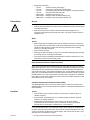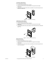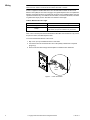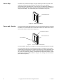
1
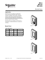
MN-S
MN-SO
MN-SDK
MicroNet Sensor
Application
MicroNet Sensors are digital room temperature
TM
sensors used with the MicroNet 2000 family of
controllers. Available in three models, all MicroNet
Sensors include industry-standard thermistors for
accurate room sensing and plug-in communication
jacks for the MicroNet Controller Interface (DOS-based
personal computer interface software).
MicroNet Sensors are suitable for direct-wall, 2 x 4
electrical box, 1/4 DIN electrical box, or surface box
mounting.
MN-SDK
Model Chart
Table-1 Model Chart.
Model
Description
Keypad
Display
MN-SDK
Deluxe
Four-button
Digital Liquid
Crystal Display
MN-SO
Sensor with
Override
One-button
Override Status
Indication Only
MN-S
Sensor Only
No
No
MN-SO
MN-S
Printed in U.S.A.
11/09
© Copyright 2009 Schneider Electric All Rights Reserved.
F-25715-4
APPLICABLE DOCUMENTATION
Table-2 Applicable Documentation.
F-Number
Description
Audience
Purpose
F-25711
MicroNet 2000 Family
Fundamentals
Guide
– Sales Personnel
– Application Engineers
Provides an introduction to the product family. Contains detailed
product descriptions, wiring practices, and system architecture
information.
F-25712
MicroNet Controller
Interface User’s Manual
–
–
–
–
Application Engineers
Installers
Start-up Technicians
Service Personnel
Provides installation instructions, startup and menu information, and
a tutorial.
F-25713
Interface Air Balance
Manual
–
–
–
–
Application Engineers
Installers
Start-up Technicians
Service Personnel
Provides step-by-step instructions for air balancing the MicroNet
VAV Controller systems.
F-25714
MN-CIM MicroNet
Controller Interface
Module Installation
Instructions
–
–
–
–
Application Engineers
Installers
Start-up Technicians
Service Personnel
Provides step-by-step installation procedures for the MicroNet
Controller Interface Module.
F-25717
MN-ASDI MicroNet
Integrator General
Instructions (ASD Bus)
–
–
–
–
Application Engineers
Installers
Start-up Technicians
Service Personnel
Provides step-by-step installation and checkout procedures for the
MicroNet Integrator.
F-25718
– Application Engineers
MN-FLO Series MicroNet
– Installers
VAV Controller Installation
– Start-up Technicians
Instructions
– Service Personnel
Provides step-by-step installation and checkout procedures for the
MicroNet VAV Controller.
F-25720
MicroNet VAV Controller
Reference Manual
–
–
–
–
Application Engineers
Start-up Technicians
Service Personnel
Building Operators
Provides MicroNet VAV Controller setup, programming, and
operating information using both the MicroNet Controller Interface
PC software and the deluxe MicroNet Sensor.
Also includes diagnostic/ troubleshooting information.
F-25722
MN-MSI MicroNet
Integrator General
Instructions (MicroSmart
Bus)
–
–
–
–
Application Engineers
Installers
Start-up Technicians
Service Personnel
Provides step-by-step installation and checkout procedures for the
MicroNet Integrator.
SOFT-MNET MicroNet VAV Controller
-101
Application Manual
– Application Engineers
– Start-up Technicians
– Service Personnel
Details all pre-engineered applications for the MicroNet VAV
Controller, including bills of material, sequence of operation, wiring,
etc.
INSTALLATION
The MicroNet Sensor is packaged disassembled in one container and consists of three
major parts:
• A pre-wirable base plate which includes a MicroNet communication jack.
• An electronic assembly containing the sensor and associated circuitry.
• A removable cover.
Inspection
Requirements
Inspect the carton for possible damage. If damaged, notify the appropriate carrier
immediately. Inspect the components for obvious damage. Return damaged products.
• Job wiring diagrams.
• Tools (not provided):
–
–
–
–
–
Appropriate screwdrivers for wiring terminals and mounting screws.
Digital Volt-ohm meter (DVM).
Level.
Drill and bits for mounting screws.
Wrist grounding strap.
• Training: Installer must be a qualified, experienced technician.
• Two appropriate mounting screws (not provided).
• Drywall screw anchors for direct-wall mount installations (not provided).
2
© Copyright 2009 Schneider Electric All Rights Reserved.
F-25715-4
• Appropriate accessories:
–
–
–
–
–
–
–
Precautions
AT-504
AT-1104
AT-1155
AT-1163
MNA-STAT-1
MNA-STAT-2
MNA-STAT-3
Auxiliary mounting base (beige)
Cast aluminum guard with steel base plate
Clear plastic guard with solid and ring base, tumbler type key lock
Wire guard with steel base plate
Replacement covers (qty. 12)
Designer inserts for MN-S model (qty. 25)
Designer inserts for MN-SO model (qty. 25)
General
Warning:
• Electrical shock hazard! Disconnect power before installation to prevent electrical shock
or equipment damage.
• Make all connections in accordance with the electrical wiring diagram and in
accordance with national and local electrical codes. Use copper conductors that are
suitable for 75°C.
Static
Caution:
• Static charges produce voltages high enough to damage the electronic components.
The microprocessor and associated circuitry within the MicroNet Sensor are extremely
sensitive to static discharge. Follow static electricity precautions when installing,
servicing, or operating the system.
• Work in a static-free area.
• Discharge any static electricity you may have accumulated. Discharge static electricity
by touching a known, securely grounded object.
• Use a wrist strap when handling the MicroNet Sensor electronic assembly. The wrist
strap clamp must be secured to earth ground.
Federal Communications Commission (FCC)
Note: This equipment has been tested and found to comply with the limits for a Class A
digital device, pursuant to Part 15 of the FCC Rules. These limits are designed to provide
reasonable protection against harmful interference when the equipment is operated in a
commercial environment. This equipment generates, uses, and can radiate radio frequency
energy and, if not installed and used in accordance with the instruction manual, may cause
harmful interference to radio communications. Operation of this equipment in a residential
area is likely to cause harmful interference in which case the user will be required to correct
the interference at his own expense.
Canadian Department of Communications (DOC)
This digital apparatus does not exceed the Class A limits for radio noise emissions from
digital apparatus set out in the radio interference regulations of the Canadian Department of
Communications.
Location
Caution:
• Avoid locations where excessive moisture, corrosive fumes, explosive vapors, or
vibration is present.
• Avoid electrical noise interference. Do not install near large contactors, electrical
machinery, or welding equipment.
• MicroNet Sensors are intended for indoor use only. Locate where ambient
temperatures do not exceed 122°F (50°C) or fall below 32°F (0°C) and relative
humidity does not exceed 95% or fall below 5%, non-condensing.
Locate the MicroNet Sensor on an inside wall where it will be exposed to unrestricted air
circulation (30 ft./minute minimum) which represents the average temperature in the room
or space. The location should be out of direct sunlight, away from sources of heat or cold,
and away from concealed ducts or pipes.
F-25715-4
© Copyright 2009 Schneider Electric All Rights Reserved.
3
Mounting
MicroNet Sensors can be direct-wall, 2 x 4 electrical box, 1/4 DIN electrical box, or surface
box mounted. Refer to Figure-1 and Figure-2 for appropriate mounting method dimensions.
3
(76.2)
Dimensions shown
are in inches (mm).
1-1/2
(38.1)
4-21/32
(118.5)
3-1/4
(82.6)
Centered
Figure-1 Mounting Dimensions for Direct-wall, 2 x 4 Electrical Box,
and Surface Box Mounting.
3
(76.2)
2-3/8
(60.3)
Centered
Dimensions shown
are in inches (mm).
1-29/32
(48.4)
4-21/32
(118.5)
Figure-2 Mounting Dimensions for 1/4 DIN Electrical Box Mounting.
Direct-wall Mount
For direct-wall mounting:
1. Use the mounting dimensions shown in Figure-1.
2. Use drywall anchors as necessary.
3. Feed the two U-LinkTM wires from the wall through the base plate feedthrough.
4. Using two appropriate screws (not provided), mount the base plate to the wall
(Figure-3).
Figure-3 Direct-wall Mounting.
4
© Copyright 2009 Schneider Electric All Rights Reserved.
F-25715-4
2 x 4 Electrical Box Mount
For 2 x 4 electrical box mounting:
1. Use the mounting dimensions shown in Figure-1.
2. Feed the two U-Link wires from the electrical box through the two base plate
feedthroughs.
3. Use two 6-32 x 5/8 in. flat head screws (not provided) to mount the base plate to the
electrical box ((Figure-4)).
Figure-4 2 x 4 Electrical Box Mounting.
1/4 DIN Electrical Box Mount
For 1/4 DIN electrical box mounting:
1. Use the mounting dimensions shown in Figure-2.
2. Feed the two U-Link wires from the electrical box through the two base plate
feedthroughs.
3. Using two appropriate screws (not provided), mount the base plate to the electrical box
((Figure-5)).
Figure-5 1/4 DIN Electrical Box Mounting.
Surface Box Mount
For surface box mounting:
1. Use the mounting dimensions shown in Figure-1.
2. Feed the two U-Link wires from the surface box through the two base plate
feedthroughs.
3. Use two 6-32 x 5/8 in. flat head screws (not provided) to mount the base plate to the
surface box (Figure-5).
Figure-6 Surface Box Mounting.
F-25715-4
© Copyright 2009 Schneider Electric All Rights Reserved.
5
Wiring
Caution: The MicroNet Sensor is a Class 2 only device and must be connected to a
Class 2 source. Class 2 circuits must not intermix with Class 1 circuits.
Power is supplied to the MicroNet Sensor from the MicroNet Controller via the U-Link.
Minimum wire quality for the U-Link is 24 gage, voice grade telephone wire. The capacitance
between conductors should be no greater than 32 pF per foot. If shielded cable is used, the
capacitance between any one conductor and the others, connected to the shield, should be
no greater than 60 pF per foot. See Table-3 for maximum wire length.
Table-3 Maximum U-Link Length.
Number of MicroNet Sensors
Single
Multiple
Maximum U-Link Length
200 ft. (61 m) from sensor to controller.
400 ft. (122 m) total segment from sensor to controller to
sensor. 200 ft. (61 m) from controller to any one sensor.
Note: The U-Link wire pairs must be dedicated to MicroNet communications. They cannot
be part of an active, bundled telephone trunk.
To connect the MicroNet Sensor to the U-Link:
1. Strip 1/4 in. (6 mm) of insulation from the U-Link wires.
2. Connect the wires to screw terminals 1 and 2. No polarity maintenance is required
((Figure-7)).
3. Push excess wire back through the base plate to minimize air flow restriction.
1
2
U-Link
Leads
Figure-7
6
U-Link Connection.
© Copyright 2009 Schneider Electric All Rights Reserved.
F-25715-4
Checkout
1. Verify that the wiring between the MicroNet Sensor base plate and the MicroNet controller
is in accordance with the job wiring diagram and with national and local wiring codes.
Note: Wiring between the sensor and the controller is not polarity sensitive. Refer to the
MicroNet 2000 Family Fundamentals, F-25711, for details.
Setting the Address
All MicroNet Sensors are shipped with the default address setting of 1. In installations where
only one MicroNet Sensor is connected to a MicroNet Controller, this default address should
not be changed. For those installations where two MicroNet Sensors are connected to one
MicroNet Controller, the address of the second sensor must be changed to 2.
To change the address on the MicroNet Sensor:
1. Turn the electronic assembly upside down so that the electronic circuitry is visible.
2. Locate the copper trace in the lower left corner of the electronic assembly ((Figure-8)).
3. Use a knife or another sharp object to cut the trace somewhere between the two “holes.”
Cut Trace
Foil
Figure-8
Electronic Assembly
and Cover Installation
Setting the Address.
After completing checkout:
1. Set the electronic assembly onto the bottom hooks of the base plate.
2. Secure the electronic assembly to the base plate by tightening the two screws at the top
of the assembly ((Figure-9)).
Electronic
Assembly
Figure-9
Electronic Assembly Installation.
Note: Prior to installation, the sensor covers and optional inserts (MNA-STAT-2 and
MNA-STAT-3) can be painted or papered to match the room decor.
3. Install the cover by inserting the bottom tabs first and snapping the top into place.
Note: Once installed, the sensor cover can be removed, if necessary. To remove the cover,
place your thumb in the middle of the sensor, grasp the top edge of the cover with your
fingers, and pull firmly.
THEORY OF OPERATION
F-25715-4
© Copyright 2009 Schneider Electric All Rights Reserved.
7
Sensor Only
The Sensor Only model has no display or keypad. Its primary function is to provide room
temperature sensing values to the MicroNet controller via the U-Link. A plug-in
communication jack is provided so that you can connect a PC (desktop or portable), via a
MicroNet Controller Interface Module, and use the MicroNet Controller Interface software to
change or view settings. The communication jack is shown below in (Figure-10).
Communication Jack
Figure-10
Sensor with Override
Sensor Only Features.
The Sensor with Override model provides the same functions as the Sensor Only model with
the addition of an override button and override status indicator. The features of the Sensor
with Override model are shown below in (Figure-11).
Override Status Indicator
Communication Jack
Override Button
Figure-11 Sensor with Override Features.
The override button allows you to override the unoccupied mode setting within the controller.
The override status indicator is lit if the MicroNet controller is overridden to the occupied
mode from the unoccupied mode. It is unlit if the controller is in the unoccupied mode or the
normal, scheduled occupied mode. A plug-in communication jack is provided so that you
can connect a PC (desktop or portable), via a MicroNet Controller Interface Module, and use
the MicroNet Controller Interface software to change or view settings. The communication
jack is shown in (Figure-11).
8
© Copyright 2009 Schneider Electric All Rights Reserved.
F-25715-4
Deluxe Sensor
The Deluxe Sensor model provides the same functions as the Sensor Only model with the
addition of a digital liquid crystal display and a four-button keypad. The features of the
Deluxe Sensor are shown below in (Figure-12).
Display
Keypad
Communication Jack
Figure-12
Deluxe Sensor Features.
The Deluxe Sensor’s display and keypad allow you to view and change certain controller
values. The database in the MicroNet Controller and your access level determine which
values can be viewed and/or changed. Refer to Table-3 for keypad functions.
Table-4 Deluxe Sensor Keypad.
Button
∧
∨
Name
Function
Up Arrow
Increases the currently displayed changeable value.
Down Arrow
Decreases the currently displayed changeable value.
SELECT
Select
Scrolls through the attribute list.
ENTER
Override
Enter/Override
Stores the displayed changeable value in memory. Pressing
and holding this key for four seconds in unoccupied mode
causes the controller to go into timed occupied mode.
A plug-in communication jack is provided so that you can connect a PC (desktop or portable)
and use the MicroNet Controller Interface software to change or view settings. The
communication jack is shown in (Figure-12).
F-25715-4
© Copyright 2009 Schneider Electric All Rights Reserved.
9
10
© Copyright 2009 Schneider Electric All Rights Reserved.
F-25715-4
F-25715-4
© Copyright 2009 Schneider Electric All Rights Reserved.
11
On October 1st, 2009, TAC became the Buildings business of its parent company Schneider Electric. This document reflects the visual identity of Schneider
Electric, however there remains references to TAC as a corporate brand in the body copy. As each document is updated, the body copy will be changed to reflect
appropriate corporate brand changes.
Copyright 2009, Schneider Electric
All brand names, trademarks and registered
trademarks are the property of their respective
owners. Information contained within this
document is subject to change without notice.
F-25715-4
Schneider Electric
1354 Clifford Avenue
P.O. Box 2940
Loves Park, IL 61132-2940
www.schneider-electric.com/buildings