1
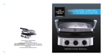
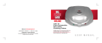
The EVEREST Initial Mesh Generator: Version 4.0
JV Ashby, RF Fowler and C Greenough
December 1998
Abstract
In this report we describe Version 4.0 of the EVEREST Initial Mesh Generator (Inimsh) which forms part of the
EVEREST semiconductor device modelling suite of programs. This module is responsible for producing the
coarse initial mesh which can be used as the starting point for automatic mesh refinement in the Solver module.
Hence only simple controls are provided to specify manual refinement of the initial mesh. The alternative mesh
generator built into the Pre-processor module should be used for manual mesh construction. Only Inimsh is
capable of meshing geometries that have planes which are not perpendicular to a major axis, as occurs if prisms
or tetrahedra are used in the blocks definition of a device.
The Inimsh mesh generator will produce a mixed mesh of hexahedral and tetrahedral elements. The more
computationally efficient hexahedral elements are produced whenever possible, with tetrahedra used to resolve
surfaces that are not parallel to a principle axis.
The EVEREST suite is one of the products of the ESPRIT project EVEREST (ESPRIT 962E-17, ThreeDimensional Algorithms for a Robust and Efficient Semiconductor Simulator with Parameter Extraction). The
original authors of the Initial Mesh Generator were L.Jin and N.Ferguson of Trinity College Dublin and J.V.Ashby
and R.F.Fowler the Rutherford Appleton Laboratory.
A copy of this report can be found at the Department’s web site (http://www.cse.clrc.ac.uk/) under page Group/CSEMSW
or anonymous ftp server www.inf.rl.ac.uk under the directory pub/mathsoft/publications
Mathematical Software Group
Computation Science & Engineering Department
Rutherford Appleton Laboratory
Chilton, DIDCOT
Oxfordshire OX11 0QX
Contents
Mesh Generator Input 1 Introduction
1
2
The command line interface . . . . . . . . . . . . . . . . . . . . . . . . . . . . . . .
The Mesh Generator Commands . . . . . . . . . . . . . . . . . . . . . . . . . . . . .
1
1
1
3 Examples and results 3.1 Diode containing one dimensional effects . . . . . . . . . . . . . . . . . . . . . . . .
3.2 Oxide corner with non-planar geometry . . . . . . . . . . . . . . . . . . . . . . . . .
3
3
3
A Internal Commands A.1 MORE - to display the contents a file . . . . . . . . . . . . . . . . . . . . . . . . . . .
A.2 CHANGE - to change working directory . . . . . . . . . . . . . . . . . . . . . . . . .
A.3 RENAME - to rename a file . . . . . . . . . . . . . . . . . . . . . . . . . . . . . . .
A.4 COPY - to copy a file . . . . . . . . . . . . . . . . . . . . . . . . . . . . . . . . . . .
A.5 RM - to delete (remove) a file . . . . . . . . . . . . . . . . . . . . . . . . . . . . . .
A.6 LIST - to provide directory listing . . . . . . . . . . . . . . . . . . . . . . . . . . . .
A.7 WRITE - to provide monitoring of a session . . . . . . . . . . . . . . . . . . . . . . .
A.8 READ - to specify a command input file . . . . . . . . . . . . . . . . . . . . . . . . .
A.9 SYNTAX - to provide the syntax of a command . . . . . . . . . . . . . . . . . . . . .
A.10 HELP - to access HELP system . . . . . . . . . . . . . . . . . . . . . . . . . . . . . .
8
9
9
9
10
10
11
11
12
12
13
B Application Commands B.1 ADAPT - to specify mesh database output file . . . . . . . . . . . . . . . . . . . . . .
B.2 END - to generate and write mesh files, then exit . . . . . . . . . . . . . . . . . . . .
B.3 GEOMETRY - to specify name of input geometry neutral file . . . . . . . . . . . . . .
B.4 MESH - to generate and write mesh files, but not exit . . . . . . . . . . . . . . . . . .
B.5 MIXED - to switch between mesh types . . . . . . . . . . . . . . . . . . . . . . . . .
B.6 NEUTRAL - to set name of output mesh neutral file . . . . . . . . . . . . . . . . . . .
B.7 QUIT - to exit without mesh generation . . . . . . . . . . . . . . . . . . . . . . . . .
B.8 RECAP - to display options entered so far . . . . . . . . . . . . . . . . . . . . . . . .
B.9 REFINE - to set maximum relative spacing along major axis . . . . . . . . . . . . . .
15
16
16
16
17
17
17
18
18
19
2.1
2.2
i
1 Introduction
This manual describes the initial mesh generation module, Inimsh, of the EVEREST semiconductor
device modelling software. This constitutes the fourth release of this software package.
The EVEREST suite [1] consists of five stand-alone modules, the Inimsh module being used to
generate a coarse initial mesh which may be automatically refined within the Solver module [4]. The
mesh generator requires the geometry of the device to be meshed and this is obtained from the Preprocessor [2], via the common neutral file interface. The output from the mesh generator is passed to
the Solver via two files which describe the mesh and the data structures necessary for refinement.
This mesh generator is more flexible than the one built into the Pre-processor module. In particular
it is able to deal with geometrical planes that are not aligned with one of the principle axes (x, y or
z). This allows the simulation of non-rectangular geometries, such as approximations to the type of
bird’s beak geometry that occurs with oxide growth next to a mask. The limitations of planar surfaces,
built from the basic primitives available in the Pre-processor, makes such approximations quite crude.
However, compared to other sources of uncertainty in three dimensional device modelling, this level
of geometric representation should be sufficient for many problems.
The operation of the mesh generator, and the command line interface to it, are described in the
following section. Some examples of the use of the mesh generator are shown in Section 3. Full
details of all the commands available within the mesh generator are given in the two appendices.
2 Mesh Generator Input
2.1 The command line interface
The mesh generator is run by typing the command inimsh, assuming that the appropriate directory
has been added to the user’s search path. Like all the modules in the EVEREST suite the initial
mesh generator uses a standard command line driven interface. All modules support a common set
of internal commands which are described in Appendix A. The application commands specific to
Inimsh are listed in Appendix B. A summary of the available commands can be obtained by typing the
command HELP. The syntax and purpose of a particular command is given by the help command with
the command name as an argument, e.g. HELP GEOMETRY. Note that commands are case insensitive
and can be abbreviated, the shortest form being indicated in the output of help commands by the part
of the name in upper case.
Though the command line interface is very flexible for interactive use it is often more convenient
in development work to place the commands in a text file. This can then be read into the module using
the command READ. If slight changes to the initial mesh are required for a subsequent run then the
commands file can be edited appropriately and re-read.
2.2 The Mesh Generator Commands
The commands for the initial mesh generator are relatively simple. It is first necessary to specify
the geometric description file, which must have previously been produced using the Pre-processor
module. This is done using the INPUT command. The file suffix (.GEO) can be omitted and all names
are mapped to uppercase.
Since this mesh generator is intended to produce a basic initial mesh which will be subsequently
refined, there is only a limited need to add refinement to it in this module. However, a completely
1
minimal mesh will only resolve those points defined by the geometry of the device. Such a mesh may
fail to refine at all because key features, such as changes in doping levels due to an ion implantation,
are not picked up by any nodes. To add a basic background mesh, beyond that set by points in the
geometry, the REFINE command can be used. Unlike the command in the mesh generator built into the
Pre-processor, this refinement command only takes an axis name and a relative node spacing for that
axis. There is no need to specify line names or refinement weighting. As an example, the following
two refinement commands,
refine x 0.1
refine y 0.1
would cause increased mesh resolution in the x and y directions with approximately 11 nodal planes
perpendicular to each of these axes. The second parameter is the typical spacing between nodal planes
along the selected axis, expressed as a fraction of the total device length in that direction. Note that
it is not possible to say exactly how many nodal planes will be generated along these axes, as each
unique point in the geometry can generate a nodal plane. These are produced first before any additional
refinement required from the REFINE commands is added. In the above case the z direction refinement
is not set so it would default to the minimum number of nodal planes to resolve the geometric points
along that axis.
The data structures that are needed by the refinement procedure within the solver are written to a
file as defined by the command ADAPT, as noted earlier. By convention this file has the suffix .DBASE
added to it. Thus the command
adapt p-n
would cause the data structures to be written to the file P-N.DBASE. This is not a neutral file, but an
unformatted binary file, which must be specified as the parameter REFILE in the command SOLVE of
the Solver module. This file is updated each time a refinement pass is made in the Solver, so it maybe
convenient to keep a backup copy of it when experimenting with mesh refinement parameters.
The other output file which needs to be specified before generation of a mesh is the mesh neutral
file. This is set by the NEUTRAL command. As with other file commands, the standard file suffix (.MSH
in this case) does not need to be supplied. To review commands that have been issued so far, the RECAP
command can be used.
By default the mesh generator will produce a mixed mesh of both hexahedral and tetrahedral
elements. Hexahedral elements are more computationally efficient than tetrahedra in this application.
Tetrahedra are required by this mesh generator to deal with any surfaces of the device which are not
parallel to one of the major axes (x, y or z). There is an option to generate a mesh of only tetrahedral
elements through the use of the command MIXED OFF. However, this is not recommended as the Solver
will run more slowly with such meshes.
Once the various files and background refinements have been set a mesh can be generated. This is
done by issuing the command END. This causes the two output files to be written and the mesh program
to terminate. In a future release the command MESH will allow a mesh to be generated and then return
to the command prompt. However, at present this command performs the same actions as the END
command.
The syntax and purpose of each command in the mesh generator is explained in detail in the two
appendices. A summary the application commands is given below.
2
ADAPT
END
GEOMETRY
MESH
MIXED
NEUTRAL
QUIT
RECAP
REFINE
to specify mesh database output file
to generate and write mesh files, then exit
to specify name of input geometry neutral file
to generate and write mesh files, but not exit
to switch between mesh types
to set name of output mesh neutral file
to exit mesh generator without mesh output
to display options entered so far
to set maximum relative spacing along major axis
3 Examples and results
This section describes two examples to illustrate the use of the initial mesh generator. The plots
subsequent to the simulation are generated by the post-processor.
3.1 Diode containing one dimensional effects
Description
The device has dimensions 10 2 5 µm in x, y and z directions and is divided into 2 blocks of equal
size with their interface at x = 5. The contacts are at x 0 and x 10. The geometry of the device and
the surface mesh generated by the listed commands are shown in Figure 1.
Input to the mesh generator
geometry
neutral
adapt
refine x
refine y
refine z
end
p-n
p-n
p-n
0.1
1
0.5
Note that as this is a one dimensional problem there is no point in having more than the minimum
refinement in the y and z directions. However, a small refinement has been used in the z direction
to illustrate the effect of the REFINE command. The latter two REFINE commands could have been
omitted to give minimal refinement in these directions.
3.2 Oxide corner with non-planar geometry
Description
This is a simple two dimensional problem where an oxide corner, surrounded by semiconductor, has
been “round-off” using two prism blocks. The input to the blocks command level of the Pre-processor
to generate this test structure are as follows:
block
neut corner
3
Z
Y
5.00
X
TRANSFORMED AXES
3.33
Z
Y
1.67
X
0.00
0.00
0.12
0.25
ANGLE OF ROTATION
0.38
Z
0.50
X101
0.62
0.75
0.88
2.00
1.00
1.00 0.00
Y
ANGLE OF ELEVATION
Figure 1: Geometry and initial mesh on the 1D diode.
4
vol
vol
vol
vol
vol
vol
vol
vol
vol
vol
con
con
gen
end
end
vox1 b (0 0 0) (2.5 2.5 1) ox
vox2 b (0 2.5 0) (2.5 2.5 1) ox
vox3 b (2.5 0 0) (2.5 2.5 1) ox
vox4 p (2.5 2.5 0) (2.5 2.5 1) ox z
vsi1 p (5 5 0) (-2.5 -2.5 1) si z
vsi2 b (0 5 0) (2.5 5 1) si
vsi3 b (2.5 5 0) (2.5 5 1) si
vsi4 b (5 0 0) (5 2.5 1) si
vsi5 b (5 2.5 0) (5 2.5 1) si
vsi6 b (5 5 0) (5 5 1) si
top r ( 0 5 0
0 10 0 0 5 1 )
bot r ( 5 0 0 10 0 0 5 0 1 )
This set of commands creates the geometry neutral file which is required by Inimsh. Note that the
Pre-processor mesh generator is not currently able to mesh geometries using prism and tetrahedral
blocks.
Input to the mesh generator
geom corner
neut corner
adapt corner
ref x .1
ref y .1
end
These commands generate a mesh of 288 nodes and 136 elements, which can be seen in Figure 2. Of
these elements, 118 are hexahedra while just 18 are tetrahedra. The latter are only used in the elements
the are cut by the sloping oxide-semiconductor surface.
5
Y
Z
X
TRANSFORMED AXES
Y
X
0.00
1.00
0.17
0.83
0.33
0.67
0.50
X10
1
0.50
0.67
0.33
0.83
0.17
Y10
ANGLE OF ROTATION
Z
1
1.00 0.00
ANGLE OF ELEVATION
Figure 2: Geometry of the oxide corner. The mesh generated by Inimsh is shown on the surface. The
light coloured area is oxide, the darker area silicon and the contact is darker still.
6
References
[1] Three dimensional algorithms for a robust and efficient semiconductor simulator with parameter
extraction: the EVEREST final report, C.Greenough, Report RAL92082, Rutherford Appleton
Laboratory, Chilton (1992).
[2] EVEREST Pre-processor user manual Version 3.0, N.Ferguson et al, Report RLUR17908, Rutherford Appleton Laboratory, Chilton (1990). Version 4.0 to be published.
[3] EVEREST Doping generator Version 3.0, G.A.Duffett and M.A.Towers, et al, Report
RLUR17907, Rutherford Appleton Laboratory, Chilton (1990). Version 4.0 to be published.
[4] EVEREST Solver user manual Version 3.0, D.Gunasekera et al, Report RLUR17906, Rutherford
Appleton Laboratory, Chilton (1990). Version 4.0 to be published.
[5] EVEREST Post-processor user manual Version 3.0, P.A.Mawby et al, Report RLUR17909,
Rutherford Appleton Laboratory, Chilton (1990). Version 4.0 to be published.
[6] RALBIC - A simple neutral file for finite element data. , C.R.Emson, Report RAL 87102, Rutherford Appleton Laboratory, Chilton (1987).
7
A Internal Commands
A.1
A.2
A.3
A.4
A.5
A.6
A.7
A.8
A.9
A.10
MORE
CHANGE
RENAME
COPY
RM
LIST
WRITE
READ
SYNTAX
HELP
- to display the contents a file
- to change working directory
- to rename a file
- to copy a file
- to delete (remove) a file
- to provide directory listing
- to provide monitoring of a session
- to redirect the input stream to read from a file
- to provide the syntax of a command
- to access HELP system
8
A.1 MORE - to display the contents a file
Syntax
MORe FILe=<string>
Description
Displays the contents of the specified file to the terminal.
Parameters
FILE
Required string
A string giving the name of the file to be displayed.
Examples
more file=ANODE
MOR CATHODE
A.2 CHANGE - to change working directory
Syntax
CHAnge DIRectory=<string>
Description
Changes the current working directory.
Parameters
DIRECTORY
Required string
A string giving the name of the new working directory.
Examples
change directory=results
CHA MODELS
A.3 RENAME - to rename a file
Syntax
REName FILe1=<string> FILe2=<string>
Description
Renames a given file to a new name.
Parameters
9
FILE1
FILE2
Required string
A string giving the current file name.
Required string
A string giving the new file name.
Examples
RENAME FILE1=RESULT1 FILE2=RESULT.SAVE
ren output1 output2
A.4 COPY - to copy a file
Syntax
COPy FILe1=<string> FILe2=<string>
Description
Copies a given file to a new file.
Parameters
FILE1
FILE2
Required string
A string giving the source file name.
Required string
A string giving the destination file name.
Examples
COPY FILE1=RESULT1 FILE2=RESULT.SAVE
cop output1 output2
A.5 RM - to delete (remove) a file
Syntax
RM FILe=<string>
Description
Removes (deletes) the given file from the file system.
Parameters
FILE
Required string
A string giving the name of the file to be removed (deleted).
Examples
RM FILE=RESULT
rm output
10
A.6 LIST - to provide directory listing
Syntax
LISt [FILe=<string>]
Description
Provide a listing of the current or specified directory.
Parameters
FILE
Optional string : initial = ” ”
A string giving the name of the file.
Examples
LIST
lis *.MSH
A.7 WRITE - to provide monitoring of a session
Syntax
WRIte STAte=<choice> [FIle=<string>]
[PROmpt=<choice>]
Description
Redirects the command decoder echo output to the file specified by the FILE parameter.
The information flow is controlled by the STATE parameter. This command can enable
the constructions of command files to drive the program in a background mode.
The echoing of the command prompt can be controlled using the PROMPT parameter.
Parameters
STATE
required choice
Controls the flow of information to the monitoring file It has
values NO, OFF or CLOSE. ON switches on monitoring. OFF
suspends it but does not close the file and CLOSE ends monitoring and closes the file.
FILE
retained string : initial = MONITOR
Output file name to receive the monitoring stream.
PROMPT
reset choice : initial = OFF
Allows you to select whether the command prompt is echoed
in the monitoring file. It has values ON or OFF.
Examples
WRITE STATE=ON FILE=MONITOR PROMPT=OFF
wri on junk on
11
A.8 READ - to specify a command input file
Syntax
REad FIle=<string> [ECHO=<choice>]
Description
Redirects the command decoder to take its input from a file specified by the FILE parameter. However, if FILE is given as TERMINAL, input returns to the standard input
stream.
The echoing of the commands being read by the decoder can be controlled using the
ECHO parameter.
Parameters
FILE
required string
Input file name containing program commands.
ECHO
reset choice : initial = OFF
Echo control option. Values can be ON or OFF.
Examples
In this example a sequence of commands are read from the file NAIL and ECHOed to the
standard output device:
Everest: read nail echo=on
A.9 SYNTAX - to provide the syntax of a command
Syntax
SYNtax [COMmand=<string>]
Description
Displays the formal syntax of all the currently defined commands. If the syntax of a specific command name is required then that name is given as a parameter to the command.
Parameters
COMMAND
retained string : initial = ALL
Specifies the commands name for which the syntax is required.
If the syntax of all the currently defined commands is required,
then the special command name ALL should be used.
Examples
The following example obtains the syntax of all the commands in the DOCUMENT program.
12
Doc: syntax
The commands currently defined are:
SYNtax [COMmand=<string>]
Help [KEY=<string>] [OPTion=<string>]
FILe INput=<string>, OUTput=<string>
PROcess
Quit
TItle TEXT=<string>
AUthor TEXT=<string>
Date TEXT=<string>
OPtions [SORT=<choice>] [CONtents=<choice>]
[RUNoff=<choice>] [FRont_page=<choice>]
For further information type: HELP <command name> [<option>],
where <option> is BRIEF or FULL
Doc:
A.10 HELP - to access HELP system
Syntax
Help [KEY=<string>] [OPTion=<choice>]
Description
Accesses to the inbuilt HELP system within the command decoder. HELP is one of the
internal commands of the command processor and has a companion command SYNTAX.
HELP has two parameters allowing the selection of help on a specific command and the
level of help required (SUMMARY, BRIEF, FULL and SYNTAX). If no command name
is given summary help is given on all the commands currently defined.
If an ambiguous or invalid command name is given a warning or error message is given.
BRIEF help gives information on the purpose, syntax and the current state of the selected
command. A table of command keywords, their type, status and current value (if applicable) is printed.
When the FULL option is used the Help System uses the inbuilt free text retrieval system
to access the help data base. This allows the display of the full command description and
the searching for specific keywords. This option is not supported in the current release.
Parameters
13
KEY
reset string : initial =
Either the global command name SUMMARY, or the specific
command name on which help is sought.
OPTION
reset choice : initial = BRIEF
The level of help required. This can be SUMMARY, BRIEF,
FULL or SYNTAX.
Examples
Everest: help output
Name
: OUTPUT
Purpose : to specify results file
Syntax : OUTput FILE=<string> [REPLACE=<choice>]
Keyword
Type
Status
Current Value
-------------------------------------------------------------FILE
REPLACE
string
choice
required
reset
14
undefined
replace,NOREPLACE
B Application Commands
B.1
B.2
B.3
B.4
B.5
B.6
B.7
B.8
B.9
ADAPT
END
GEOMETRY
MESH
MIXED
NEUTRAL
QUIT
RECAP
REFINE
- to specify mesh database output file
- to generate and write mesh files, then exit
- to specify name of input geometry neutral file
- to generate and write mesh files, but not exit
- to switch between mesh types
- to set name of output mesh neutral file
- to exit mesh generator without mesh output
- to display options entered so far
- to set maximum relative spacing along major axis
15
B.1 ADAPT - to specify mesh database output file
Syntax
APapt [NAme=<string>]
Description
Sets the output file name for the binary mesh data structure. This file is required as input
to the Solver.
Parameters
NAME
Retained string
A string giving the name of the file to write. The name is
mapped to uppercase with the extension .DBASE
Examples
ADAPT
P-N
B.2 END - to generate and write mesh files, then exit
Syntax
END
Description
This command causes the mesh to be generated and, if this is successful, to write the
neutral file for the mesh and the associated binary file. The program is then exited.
Parameters
None
Examples
END
B.3 GEOMETRY - to specify name of input geometry neutral file
Syntax
GEOMetry [NAme=<string>]
Description
Sets the input file name for the geometry neutral file. This file is required as input.
Parameters
NAME1
Retained string
A string giving the geometry neutral file name.
Examples
GEOMETRY P-N
16
B.4 MESH - to generate and write mesh files, but not exit
Syntax
MEsh
Description
Currently behaves as END and does exit the program.
Parameters
None
Examples
MESH
B.5 MIXED - to switch between mesh types
Syntax
MIXed [OPTion=<choice>]
Description
By default a mixed mesh is generated with hexahedra wherever possible and tetrahedra
only if required for non-axes aligned surfaces. Setting this command to OFF causes a
purely tetrahedral mesh to be produced. This is NOT recommended.
Parameters
OPTION
Required choice : initial = ”ON”
A choice giving the state of mixed mesh generation.
Values=(ON,OFF).
Examples
MIXED on
Mix off
B.6 NEUTRAL - to set name of output mesh neutral file
Syntax
NEUtral [NAme=<string>]
Description
This sets the output name for the neutral file to store the mesh. The name is mapped to
uppercase and the .MSH suffix added if required.
17
Parameters
NAME
retained string
Name of the mesh neutral file to be written.
Examples
neutral p-n
B.7 QUIT - to exit without mesh generation
Syntax
QUit
Description
This command quits the mesh generator without producing any output.
Parameters
None
Examples
Quit
B.8 RECAP - to display options entered so far
Syntax
REcap
Description
Displays the commands which have been entered so far.
Parameters
None
Examples
REC
18
B.9 REFINE - to set maximum relative spacing along major axis
Syntax
REFine AXis=<choice> [Spacing=<real>]
Description
Set the maximum relative spacing along an axis. Without these values only sufficient
nodal planes are generated to resolve the geometric points. A refinement of 1.0 gives no
additional planes, while 0.1 will give about 10 planes.
Parameters
AXIS
required choice
The axis to refine. Values=(X,Y,Z).
SPACING
optional real : initial = 1.0
The maximum relative spacing to use.
Examples
refine x 1
ref y 0.2
19