1
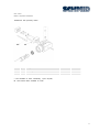
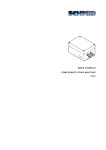
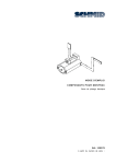
USER MANUAL
MONTRAC COMPONENTS
ShuttleLock
BA-100067
starting from serial number 421830
english, edition 05/2007
User manual
Montrac Components ShuttleLock
Contents
1.
Important information ________________________________________________________________2
1.1.
Introduction ____________________________________________________________________ 2
1.2.
EU - conformance (to EU Directive on Machines, Appendix II A) ____________________ 2
1.3.
EMV-Guideline _________________________________________________________________ 2
1.4.
Product description and application ________________________________________________ 3
1.5.
System logistics ________________________________________________________________ 3
1.6.
Safety instructions ______________________________________________________________ 3
1.7.
Dangers ______________________________________________________________________ 3
1.8.
Additional information ____________________________________________________________ 4
1.9.
Validity of the User Manual ______________________________________________________ 4
2.
Technical Data _____________________________________________________________________5
2.1.
Technical Data _________________________________________________________________ 5
2.2.
Dimension sheet _______________________________________________________________ 5
2.2.1. ShuttleLock ____________________________________________________________________ 5
3.
Installation and commissioning ________________________________________________________6
4.
Maintenance _______________________________________________________________________8
5.
Parts list ___________________________________________________________________________ 9
5.1.
ShuttleLock ____________________________________________________________________ 9
5.2.
Parts list ShuttleLock ___________________________________________________________ 10
6.
General information ________________________________________________________________12
6.1.
Environmental compatibility and disposal ____________________________________________ 12
1
User manual
Montrac Components ShuttleLock
1.
Important information
1.1.
Introduction
This operating instruction describes the mechanical design, the load limits, installation, maintenance
and spare parts of the TracShuttleLock.
1.2.
EU - conformance (to EU Directive on Machines, Appendix II A)
Regulations and standards taken into account:
A Montrac transport system is a machine that consists of, depending on the application, a variety of
precisely defined components. The regulations and standards taken into account for the components
are mentioned in the respective sub-chapter of the operating instructions
Montrac transport systems may only be put into operation,
a) when they are operated with a power supply that complies with the standards described in the
operating instructions.
b) when the space beneath transfer gates and crossings is inaccessible in an area with a diameter
of 1.6 m (Danger of crash for shuttles if transfer gate or crossing is incorrectly switched.)
Manufacturer
SCHMID Group| montratec AG
Zeilmattenring 6
4563 Gerlafingen
Tel. +41 32 55 88 700, Fax. +41 32 55 88 799
1.3.
EMV-Guideline
Emission:
– EMC directives: Noise field intensity according to EN 55011 or EN 55022, Class A.
Immunity:
– To electromagnetic fields according to 801-3: 10 V/m, 1 kHz, 80% AM.
– To burst according to IEC 801-4: 2 kV.
– To line-carried, narrow-band noise according to IEC 801-6: 10 VEMF.
– To 50 Hz magnetic fields according to EN 61000-4-8: 30 A/m.
– To discharge of static electricity.
– To conducted noise.
2
User manual
Montrac Components ShuttleLock
1.4.
Product description and application
Montrac is a monorail transport system with self-propelling shuttles, constructed to carry loads of up
to 12 kg or 24 kg (2-axle shuttle) and pallet sizes up to 300 x 550 mm. Montrac is a modular
system. Standardized basic components enable customer-specific system configurations to be set up
for connection to machining stations, machines, order-picking stations, etc.
Montrac can be used wherever material has to be moved, distributed, processed stepwise
assembled) or collected together at one point from various senders.
1.5.
(e.g.
System logistics
The ShuttleLock serves to localize the Shuttle at a SupoTrac or on the lift.
1.6.
Safety instructions
The safety instructions, especially those concerning the electrical connection, must be heeded during
commissioning, operation, repair work and decommissioning. Non-compliance with these instructions is
an improper use of the transport system and its components.
The operation of a Montrac transport system in an explosive atmosphere (combustible gases, vapors
or dust) may lead to their ignition and must therefore not be carried out.
1.7.
Dangers
In order to exclude dangers under operating conditions, the requirements specified in the EU
Declaration of Conformity with regard to a) the electrical supply and b) the safety equipment must
be fulfilled.
3
User manual
Montrac Components ShuttleLock
1.8.
Additional information
The aim of the present operating instructions is to enable users to employ ShuttleLock correctly and
safely. Should further information be required relating to the particular application, do not hesitate to
contact the manufacturer.
When ordering user manual it is essential to quote the type and serial number.
Additional operating instructions can be obtained from our homepage www.montratec.com.
1.9.
Validity of the User Manual
Our products are continually updated to reflect the latest state of the art and practical experience.
In line with product developments, our User Manuals are continually updated.
Every User Manual has an article number e.g. BA-100067.
The article number and the date of edition are evident on the title page.
4
User manual
Montrac Components ShuttleLock
2.
Technical Data
2.1.
Technical Data
Weight
[kg]
Connected voltage
[V DC]
Current consumption
Ambient conditions:
[A]
Temperature
[°C]
0.560
24
0.5
10 – 40
Rel. humidity
90% without condensation
Air purity
Air purity Atmosphere for the assembly of
precision mechanical products
2.2.
Dimension sheet
2.2.1.
ShuttleLock
ShuttleLock with proximity switch
5
User manual
Montrac Components ShuttleLock
3.
Installation and commissioning
Travel direction U
A- cam
IRM
6
ShuttleLock
AB- cam
1. Secure the IRM at the desired
stopping point.
2. Next, mount the A cam, the AB
cam as well as the ShuttleLock
as per the given distances.
3. Connect the IRM and the
ShuttleLock to the power supply
(refer to the IRM operating
instructions for information on
wiring and functional options).
4. To check the position of the
ShuttleLock, allow a Shuttle to
pass over the AB cam (its speed
is lowered) and the A cam
(Shuttle stops). If the IRM has
been fitted in the correct position,
the LED will illuminate yellow. The
pin of the ShuttleLock will extend.
5. Now check whether the pin has
extended centrally in the recess at
the bottom of the Shuttle. If not,
move the ShuttleLock into the
correct position.
User manual
Montrac Components ShuttleLock
Travel direction GU
1.
2.
A- cam
AB- cam
3.
IRM
ShuttleLock
4.
5.
Secure the IRM at the desired
stopping point.
Next, mount the A cam, the
AB cam as well as the
ShuttleLock as per the given
distances.
Connect the IRM and the
ShuttleLock to the power
supply (refer to the IRM
operating instructions for
information on wiring and
functional options).
To check the position of the
ShuttleLock, allow a Shuttle to
pass over the AB cam (its
speed is lowered) and the A
cam (Shuttle stops). If the
IRM has been fitted in the
correct position, the LED will
illuminate yellow. The pin of
the ShuttleLock will extend.
Now check whether the pin
has extended centrally in the
recess at the bottom of the
Shuttle. If not, move the
ShuttleLock into the correct
position.
7
User manual
Montrac Components ShuttleLock
Proximity switch
1.
2.
3.
4.
4.
Make the ShuttleLock currentless, then
screw the proximity switch, position 300,
into the holder, position 10, until it
touches the pin, position 60.
Now screw back the proximity switch
approx. one quarter of a turn and fix in
position using the hexagonal nut, position
310.
The pin must not make contact with the
proximity switch.
When the ShuttleLock is in a released
state, the LED in the proximity switch will
illuminate green. On locking, the LED will
no longer remain illuminated.
Maintenance
Every 6 months.
Operational check:
Check for the smooth running of the pin.
Proximity switch check:
The optional proximity switch in the ShuttleLock is to be checked for signs of damage (e.g.
mechanical wear of the proximity switch cap as well as operation of the LED). Damaged proximity
switches must be replaced.
8
User manual
Montrac Components ShuttleLock
5.
Parts list
5.1.
ShuttleLock
9
User manual
Montrac Components ShuttleLock
5.2.
Item
Parts list ShuttleLock
Sym.
Designation
Art.-Nr.
Material
◘
ShuttleLock
56925
Various
10
◊
Holder
56922
Aluminium
20
◊
Holder
56898
Aluminium
30
◊
Cylinder
56923
Steel
40
◊
Sleeve
57182
Aluminium
50
◊
Cover plate
57236
Aluminium
60
◊
Pin
56902
Steel
70
◊
Spanner
41188N
Aluminium
80
◊
Roll
43123
Steel
90
◊
Ring
57186
NBR
100
◊
Buffer
57185
NBR
110
◊
Pressure spring
56979
Steel
120
◊
Magnet26x52
520182
Steel / Copper
130
◊
Cable connection M8
505828
Brass
140
◊
Cable
505827
Plastics
150
◊
Sleeve
520291
Plastics
160
◊
Socket cap screw M 5x50
502517
Steel
170
◊
Socket cap screw M 3x12
502504
Steel
180
◊
Countersunk screws M4x8
505322
Steel
190
◊
Ribbed washer M5x9x0.6
505254
Steel
210
◊
Dowel pin ø 2.5x 10 h6
502014
Steel
200
◊
Ribbed washer M3x5.5x0.45 BN792
505385
Steel
◊ Not available ex stock individually (upon request)
◘ Price-listed items available ex stock
10
User manual
Montrac Components ShuttleLock
ShuttleLock with proximity switch
Item
Sym.
Designation
Art.-Nr.
Material
300
◘
Proximity switch PNP M4x0.5x22
520292
Steel
310
◊
Screw nut M4x0.5
Steel
◊ Not available ex stock individually (upon request)
◘ Price-listed items available ex stock
11
User manual
Montrac Components ShuttleLock
6.
General information
6.1.
Environmental compatibility and disposal
Materials used:
– Aluminium
– Copper
– Steel
– rubber (NBR)
Surface treatment:
– Anodization of aluminium
– Nickel-plating of brass and steel
– Galvanizing of steel
Shaping processes:
– Extrusion of aluminium
– Machining of aluminum, steel
– Water jet cutting of plastics
Emissions during operation
– See EMC emissions
Disposal:
ShuttleLock which cannot be used any more should be recycled not as complete units but after
dismantling into individual parts, according to type of material. The type of material for each part is
shown in the spare parts lists. Material which cannot be recycled should be appropriately disposed
of.
12