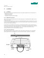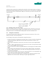
1
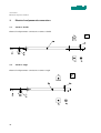
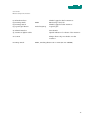
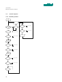
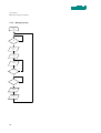
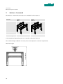
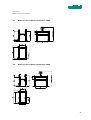
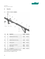
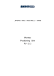
USER MANUAL
MONTRAC COMPONENTS
TracDoor
BA-100049
Starting from serial number 432699
english, edition 09/2007
User manual
Montrac Components TracDoor
Contents
1.
Important information ____________________________________________________________ 3
1.1.
Introduction______________________________________________________________________ 3
1.2.
EU - conformance (to EU Directive on Machines, Appendix II A) ________________________ 3
1.3.
EMV-Guideline ___________________________________________________________________ 3
1.4.
Product description and application_________________________________________________ 3
1.5.
System logistics __________________________________________________________________ 4
1.6.
Safety instructions ________________________________________________________________ 4
1.7.
Dangers _________________________________________________________________________ 4
1.8.
Additional information ____________________________________________________________ 5
1.9.
Validity of the User Manual ________________________________________________________ 5
2.
Technical Data ___________________________________________________________________ 6
2.1.
Technical Data ___________________________________________________________________ 6
2.2.
Loading limits ____________________________________________________________________ 6
2.3.
Throughput times_________________________________________________________________ 7
2.4.
Dimension sheet__________________________________________________________________ 8
2.4.1.
Dimension sheet TracDoor double L=3000mm 56954 _________________________________ 8
2.4.2.
Dimension sheet TracDoor single L=2000mm 56953 __________________________________ 9
3.
Electrical and pneumatic connections _____________________________________________ 10
3.1.
TracDoor double ________________________________________________________________ 10
3.2.
TracDoor single _________________________________________________________________ 10
3.3.
Control sequence________________________________________________________________ 12
3.3.1.
Normal operation________________________________________________________________ 12
3.3.2.
Through passage ________________________________________________________________ 13
3.3.3.
Emergency stop _________________________________________________________________ 14
4.
Scope of delivery _______________________________________________________________ 15
4.1.
TracDoor double ________________________________________________________________ 15
4.2.
TracDoor single _________________________________________________________________ 15
1
User manual
Montrac Components TracDoor
5.
Installation _____________________________________________________________________ 16
5.1.
Installation _____________________________________________________________________ 16
5.1.1.
Mechanical connection ___________________________________________________________ 16
5.1.2.
Electrical connection_____________________________________________________________ 16
5.1.3.
Discharge of the electrostatic charge ______________________________________________ 17
5.2.
Setting the Trac transitions _______________________________________________________ 17
5.3.
Setting the locking system _______________________________________________________ 18
5.4.
Setting the end stops ____________________________________________________________ 18
6.
Maintenance ___________________________________________________________________ 19
7.
Quickset – Framework __________________________________________________________ 20
7.1.
Dimension sheet Quickset-Framework 92064 _______________________________________ 21
7.2.
Dimension sheet Quickset-Framework 92066 _______________________________________ 21
8.
Parts list _______________________________________________________________________ 22
8.1.
TracDoor double L=3000mm _____________________________________________________ 22
8.2.
TracDoor single L=2000mm ______________________________________________________ 23
9.
General information ____________________________________________________________ 24
9.1.
Environmental compatibility and disposal __________________________________________ 24
2
User manual
Montrac Components TracDoor
1.
1.1.
Important information
Introduction
This operating instruction describes the mechanical design, the load limits, installation, maintenance
and spare parts of the TracDoor.
1.2.
EU - conformance (to EU Directive on Machines, Appendix II A)
Regulations and standards taken into account:
A Montrac transport system is a machine that consists of, depending on the application, a variety of
precisely defined components. The regulations and standards taken into account for the
components are mentioned in the respective sub-chapter of the operating instructions.
Montrac transport systems may only be put into operation,
a) when they are operated with a power supply that complies with the standards described in the
operating instructions.
b) when the space beneath transfer gates and crossings is inaccessible in an area with a diameter
of 1.6 m (Danger of crash for shuttles if transfer gate or crossing is incorrectly switched.)
Manufacturer
Montech AG, Gewerbestrasse 12 CH–4552 Derendingen
Tel. +41 32 681 55 00, Fax +41 32 682 19 77
1.3.
EMV-Guideline
Emission:
– EMC directives: Noise field intensity according to EN 55011 or EN 55022, Class A.
Immunity:
– To electromagnetic fields according to 801-3: 10 V/m, 1 kHz, 80% AM.
– To burst according to IEC 801-4: 2 kV.
– To line-carried, narrow-band noise according to IEC 801-6: 10 VEMF.
– To 50 Hz magnetic fields according to EN 61000-4-8: 30 A/m.
– To discharge of static electricity.
– To conducted noise.
1.4.
Product description and application
Montrac is a monorail transport system with self-propelling shuttles, constructed to carry loads of
up to 12 kg or 24 kg (2-axle shuttle) and pallet sizes up to 300 x 550 mm. Montrac is a modular
system. Standardized basic components enable customer-specific system configurations to be set
up for connection to machining stations, machines, order-picking stations, etc.
Montrac can be used wherever material has to be moved, distributed, processed stepwise (e.g.
assembled) or collected together at one point from various senders.
3
User manual
Montrac Components TracDoor
1.5.
System logistics
The TracDoor is intended to permit passage through a Montrac line or access to manual workplaces
within the line.
It is an automatic device and thus has its own supporting structures. Through passage is permitted
for one person as a minimum and for a small fork-lift truck as a maximum (2 versions). The principle
of TracDoor is very single. The gate is fixed at a pivot point and can be manually opened and
rotated in the opening direction up to a rubber peg with a magnet. On closing, the gate is rotated
up to an end stop and can then be manually locked again.
If a person wishes to pass through the TracDoor, he or she must first log on beforehand on the
logon/logoff button. The release lamp flashes. The shuttles are stopped and, as soon as the gate is
free, it is then released for passage (lamp lights up continuously). It can then be opened manually.
After passing through, the person must close the gate again manually, lock it by means of the lock
and log off on the logon/logoff button so that the shuttles are started again.
1.6.
Safety instructions
The safety instructions, especially those concerning the electrical connection, must be heeded
during commissioning, operation, repair work and decommissioning. Non-compliance with these
instructions is an improper use of the transport system and its components.
The operation of a Montrac transport system in an explosive atmosphere (combustible gases,
vapors or dust) may lead to their ignition and must therefore not be carried out.
1.7.
Dangers
In order to exclude dangers under operating conditions, the requirements specified in the EU
Declaration of Conformity with regard to a) the electrical supply and b) the safety equipment must
be fulfilled.
For setup or test purposes, particular attention must be paid to the shear and crushing points.
During operation, the TracDoor must be screwed to the floor or appropriately secured.
When mounting the TracDoor on the supporting structure, it must be ensured that the supporting
structure is secured beforehand.
4
User manual
Montrac Components TracDoor
1.8.
Additional information
The aim of the present operating instructions is to enable users to employ TracDoor correctly and
safely. Should further information be required relating to the particular application, do not hesitate
to contact the manufacturer.
When ordering user manual it is essential to quote the type and serial number.
Additional operating instructions can be obtained from our homepage www.montech.com.
Nameplate
Order number
Product name
Serial number
MONTECH AG
Management
U. D. Wagner
1.9.
C. Wullschleger
Validity of the User Manual
Our products are continually updated to reflect the latest state of the art and practical experience.
In line with product developments, our User Manuals are continually updated.
Every User Manual has an article number e.g. BA-100049.
The article number and the date of edition are evident on the title page.
5
User manual
Montrac Components TracDoor
2.
Technical Data
2.1.
Technical Data
Length tolerance of the TracDoor
[mm]
Material
Aluminium, Copper nickel plates, Plastic
Connected voltage
Ambient conditions:
2.2.
±2
[V DC]
Temperature
[°C]
24
10 – 40
Rel. humidity
5 - 85% (without condensation education)
Air purity
Air purity Atmosphere for the assembly of
precision mechanical products
Loading limits
Electrical loadability
between the Trac connections
[A]
64
on the movable Trac section
[A]
5
Mechanical loadability
[N]
340*
* corresponds to the force of a fully loaded two-axis shuttle.
6
User manual
Montrac Components TracDoor
2.3.
Throughput times
Applicable conditions:
The times shown below are applicable only for the configurations shown in the drawings.
The dimensions contained in the drawings are minimum dimensions for which the manufacturer can
guarantee satisfactory operation. The throughput times are obtained at a throughput speed of
v = 30 m/min.
Throughput times
TracDoor double
Shuttle 200x300
a1) = 250mm
Shuttle 300x400
a1) = 350mm
Shuttle 200x550
a1) = 600mm
With alu
platform
without
load
With alu
platform
and max.
load
With alu
platform
without
load
With alu
platform
and max.
load
With alu
platform
without
load
With alu
platform
and max.
load
5.9 s
6.1 s
6.1 s
6.3 s
6.4 s
6.6 s
TracDoor single
3.8 s
4.0 s
4.0 s
4.2 s
4.3 s
4.5 s
1)
The dimensions of a are for shuttle logoff with dropping logoff sensor signals. For shuttle
logoff with rising logoff sensor signal, the values for a should be increased by 70 mm in
each case.
7
User manual
Montrac Components TracDoor
2.4.
Dimension sheet
2.4.1. Dimension sheet TracDoor double L=3000mm 56954
8
User manual
Montrac Components TracDoor
2.4.2. Dimension sheet TracDoor single L=2000mm 56953
9
User manual
Montrac Components TracDoor
3.
Electrical and pneumatic connections
3.1.
TracDoor double
Electrical and pneumatic connections TracDoor double
3.2.
TracDoor single
Electrical and pneumatic connections TracDoor single
10
User manual
Montrac Components TracDoor
E1 Infrared interface
E2 Proximity switch
E3 Proximity switch
E4 Logon/logoff button
M8x1
Pulse frequency
Shuttle logged on before TracDoor
Monitoring of the lock
Shuttle logged off after TracDoor
Logon/logoff
A1 Infrared interface
A5 Continuous light module
Start shuttle
Optical indication for release of the TracDoor
Z Counter
Always allows only one shuttle over the
TracDoor
Proximity switch:
M8x1, switching distance Sn = 4 mm (Art. No. 508845)
11
User manual
Montrac Components TracDoor
3.3.
Control sequence
3.3.1. Normal operation
START
Normal
operation
Z-1
yes
ja
E4
no
See „Passage" sequence
E3
no
E1 & Z=0 & E4 & E2
yes
yes
ja
yes
ye
x
no
E2
E4
no
See „Passage" sequence
yes
ja
yes
Z-1
E2
no
See „Emer. off" sequence
yes
Start Shuttle
A1
E4
no
See „Passage" sequence
yes
E2
no
See „Emer. off" sequence
ja
Z+1
E4
no
See „Passage" sequence
no
See „Emer. off" sequence
i
yes
E2
yes
ja
E2
ye
s
12
no
no
See „Emer. off" sequence
User manual
Montrac Components TracDoor
3.3.2. Through passage
yes
START
Passage
E4
E2
no
no
See „Emer. off" sequence
yes
yes
E2
no
See „Emer. off" sequence
no
See „Emer. off" sequence
Lamp A5 (green)
off
yes
Lamp A5
(green)
flashes
E2
yes
Z-1
yes
E3
no
Z=0
yes
no
no
E
See „Emer. off" sequence
yes
Lamp A 5 (green)
constant
Open Gate (E2)
E2
"Passage"
Close Gate (E2)
E2
E4
no
yes
13
User manual
Montrac Components TracDoor
3.3.3. Emergency stop
START
Emer. off
E2
yes
Power off on
TracDoor
Lamp A5 (green)
constant
Colse Gate
(E2)
E2
yes
E4
yes
Power on on
TracDoor
Lamp A5 (green)
off
14
no
User manual
Montrac Components TracDoor
4.
Scope of delivery
4.1.
TracDoor double
The complete delivery of a TracDoor includes the following components:
An inlet and outlet trac, (without TracLink) two gates, one lock, two guides, a logon and logoff
button, a release lamp, and two end stops, and supporting profiles
Not included are:
– stop/start control element
– the holder
– the sensors for the shuttle logoff
– the Quick-Set supporting structures.
4.2.
TracDoor single
The complete delivery of a TracDoor includes the following components:
An inlet and outlet trac, (without TracLink) one gate, one lock, one guides, a logon and logoff
button, a release lamp, and two end stops, and supporting profiles.
Not included are:
– stop/start control element
– the holder
– the sensors for the shuttle logoff
– the Quick-Set supporting structures.
15
User manual
Montrac Components TracDoor
5.
Installation
5.1.
Installation
The TracDoor must be connected in three ways to the system components to be connected to it:
– Mechanical connection
– Electrical connection
– Discharge of the electrostatic charge
5.1.1. Mechanical connection
This connetion is performed at the two rail sections by means of TracLink (Art.No. 56056, see user
manual „Trac Link“).
It should be ensured that the rail sections are exactly flush with the system components (e.g. Tracs)
to be connected. Lateral alignment errors of more than 0.5 mm lead to inexact transitions between
the rail sections within the TracDoor.
It should also be ensured that the rail sections are exactly flush with the system components (e.g.
Tracs) to be connected, also in the vertical direction. This should be corrected by means of the feet
of the supporting structure. Vertical alignment errors of more than 0.5 mm lead to inexact
transitions between the rail sections within the TracDoor.
5.1.2. Electrical connection
The electrical connection of the connection tracs to the system components to be connected to
them is implemented as described in the section entitled "TracLink", subsection "Installation".
brown
white
16
brown
white
User manual
Montrac Components TracDoor
Since the TracDoor represents an opening in the system (also in the electrical circuit), an electrical
bridge must be produced between the ends of the connection tracs. The connections of this bridge
are connected to the two TracLink (Art.No. 56056, see user manual „Trac Link“) at the ends of the
connection Tracs.
5.1.3. Discharge of the electrostatic charge
When connecting the TracDoor to the incoming or departing system components (e.g. Tracs) by
means of a Trac connection (Art.No. 56056, see user manual „Trac Link“) it is essential to ensure
that each rail section is connected with an earthing cable "Trac earth" and with a screw.
5.2.
Setting the Trac transitions
The transitions between the movable gate and the connecting tracs may have an offset of max.
0.5mm in the region of the running surfaces.
The following procedure must be followed when setting the transitions:
– The gate is fastened to the supporting structure by means of the SLL mounted on the guide and
can thus be subsequently adjusted in the vertical and horizontal directions relative to the
connection trac.
– Once the gate is flush with the connection trac, the screws of the SLL are each tightened with
6Nm.
– In order to adjust the gap between gate and connection trac, the SLL of the spacer tube and the
corner connector EV3/45° must be loosened.
– The gate can then be moved in the longitudinal direction so that the gap is min. 0.5mm and max.
0.8mm.
– Once the gate has been adjusted, both connections must be tightened again, each with 6Nm.
– In order to adjust the Trac transition on the side of the locking system, all that is necessary is to
loosen the SLL of the bracket.
– The gate is pretensioned by means of the strut so that the transition is no more than 0.5mm. The
screws of the SLL can then be tightened again, each with 6Nm.
– The gap on the side of the locking system, i.e. between the two supporting structures can be
adjusted to min. 0.5 mm and max. 1.0 mm by moving the supporting structure.
17
User manual
Montrac Components TracDoor
5.3.
Setting the locking system
– Any alignment errors between gate / gate or gate / connection trac can be compensated by
means of the locking system.
– Slightly slacken all screws of the locking system.
– Compensate alignment errors in the horizontal direction (vertical alignment errors cannot be
compensated with the locking system and tighten screws again).
5.4.
Setting the end stops
– The open end stop must be moved up or down, until the rubber cushions are in the middle of
the gate support.
– If the installation angle of the end stop is not correct, the end stop must be clamped into the
spacer using a screw clamp. After that, slightly loosen the screws of the corner connector of the
guide and align the gate with the inward or outward transfer Trac. Then retighten screws with a
torque of 6Nm.
18
User manual
Montrac Components TracDoor
6.
Maintenance
Every 6 months
Checking the electrical Trac connection:
By slight pressure on the current-carrying rails at the transitions, it is possible to determine whether
the electrical connection is satisfactory. If the current-carrying rails are springy, the contact pieces
on the inside should be tightened according.
Checking the distance:
The distance between two Trac sections should be checked and should be tightened according to
Section Istallation.
Check conductor rails:
The conductor rails should be checked for signs of burning, grease spots or excessive soiling. These
areas should be cleaned with abrasive paper (grain size finer than 300) or with aluminum-rubber.
The produced rubber abrasion must be removed from the Trac.
– The black layer (graphite abrasion) should not be removed. It is electrically
conductive and prevents rapid oxidation of the copper!
Clean TracCurve:
The TracCurve must be freed from excessive dirt as well as from oil and grease. Remove excessive
dirt and dust with a dry cloth. Dirt on the Trac is best removed with aluminum rubber. The
produced rubber abrasion must be removed from the Trac.
Checking the play of the pivot point:
If a noticeable play of > 1 mm is present when the gate is moved vertically, this can be adjusted
again by tightening the two nuts on the bracket of the guide so that the gate is still easily rotatable
without marked play.
Checking the locking system:
In the locking system, the pin must be checked. If it can be moved easily, the springy thrust piece
must be adjusted so that locking in the end positions is readily detectable on moving the pin.
Prior to each readjustment, apply threadlocker to the pressure pad.
If the pin has scratches, it must be changed using the hand lever.
Checking the sensor:
Check the sensor in the locking system for damage (for example, mechanical wear of the sensor
cap). Replace damaged sensors.
Also check the position of the sensor. In addition, secure the sensor with a locknut.
General check:
The Trac should be checked for damage. In the event of damage, please contact MONTECH.
19
User manual
Montrac Components TracDoor
7.
Quickset – Framework
The Quickset – Framwork structures are not included for the TracDoors.
Overview
Art.No.
92064
TracDoor double
2x
TracDoor single
1x
Art.No.
92066 1)
1x
1) This Quick-Set framwork structures is to install on the side of the lock.
The standard height is 900 mm. However, this can be adapted to customer requirements.
Height 900mm
Quick-Set height
20
User manual
Montrac Components TracDoor
7.1.
Dimension sheet Quickset-Framework 92064
7.2.
Dimension sheet Quickset-Framework 92066
21
User manual
Montrac Components TracDoor
8.
Parts list
8.1.
TracDoor double L=3000mm
Pos.
Sym. Designation
Art.-Nr.
Material
◘
TracDoor double L=3000mm complet
56954
Various
10
◊
Inward transfer Trac long
57151
Various
20
◊
Door complete
57141
Various
30
◊
Door complete
57150
Various
40
◊
Outward transfer Trac long
57158
Various
50
◊
Guide
92068
Various
60
◊
End stop open
92069
Various
70
◊
End stop close
92070
Various
80
◊
Locking system complete
92071
Various
90
◊
Release lamp
92072
Various
100
◊
Logon / logoff button complete
92073
Various
110
◊
Door support
92079
Various
● These are wearing parts and available ex stock.
◊ Not available ex stock individually (upon request).
◘ Price-listed items available ex stock.
22
User manual
Montrac Components TracDoor
8.2.
TracDoor single L=2000mm
Pos.
Sym. Designation
Art.-Nr.
Material
◘
TracDoor single L=2000mm complet
56953
Various
10
◊
Inward transfer Trac long
57162
Various
20
◊
Door complete
57150
Various
30
◊
Outward transfer Trac long
57158
Various
40
◊
Guide
92068
Various
50
◊
End stop open
92069
Various
60
◊
End stop close
92070
Various
70
◊
Locking system complete
92071
Various
80
◊
Release lamp
92072
Various
90
◊
Logon / logoff button complete
92073
Various
100
◊
Door support
92079
Various
● These are wearing parts and available ex stock.
◊ Not available ex stock individually (upon request).
◘ Price-listed items available ex stock.
23
User manual
Montrac Components TracDoor
9.
General information
9.1.
Environmental compatibility and disposal
Materials used:
– Aluminium
– Copper nickel plates
– Brass
– Steel
– Bronze
– Polyethylene (PE)
– Polyamide (PA)
– Polyurethane (PUR)
– Polyvinyl chloride (PVC)
– Polycarbonate (PC)
– Thermoplastic, prevulcanized rubber (TPR)
Surface treatment:
– Anodization of aluminium
– Nickel-plating of brass and steel
– Galvanizing of steel
Shaping processes:
– Extrusion of aluminium
– Machining of aluminium, steel, bronze, PE, PA
– Casting of aluminium
Emissions during operation
– See EMC emissions
Disposal:
TracDoors which cannot be used any more should be recycled not as complete units but after
dismantling into individual parts, according to type of material. The type of material for each part is
shown in the spare parts lists. Material which cannot be recycled should be appropriately disposed
of.
24