1
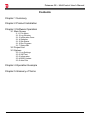
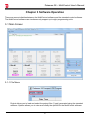
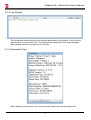
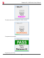
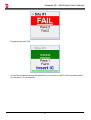
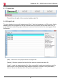
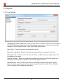
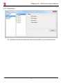
Dataman-S6 – MultiControl User's Manual
Dataman-S6
Compact USB Programmer
MultiControl User's Manual
Dataman-S6 – MultiControl User's Manual
Contents
Chapter 1 Summary
Chapter 2 Product Installation
Chapter 3 Software Operation
3-1 Main Screen
3-1-1 File Menu
3-1-2 Log Window
3-1-3 Information Pane
3-1-4 Statistics
3-1-5 Site Status
3-1-6 Run Program
3-1-7 Status Bar
3-2 Project List
3-3 Options
3-3-1 Log Settings
3-3-2 Self Test
3-3-3 Information
3-3-4 BIOS Update
3-3-5 Auto Run
Chapter 4 Operation Example
Chapter 5 Glossary of Terms
Dataman-S6 – MultiControl User's Manual
Chapter 1 Summary
This MultiControl software allows for up to 8 Dataman-S6 programmers to be controlled by one
piece of software on one PC. Project files (*.lpprj) are generated using the standard software, these
are then loaded into the MultiControl software and assigned to the connected programmers. The
MultiControl software will then carry out the actions specified in the project file on the connected
programmers.
Dataman-S6 – MultiControl User's Manual
Chapter 2 Product Installation
Before installation of the MultiControl software make sure that you have already installed the
standard version of the software and database, otherwise it will cause the installation to fail.
1
Dataman-S6 – MultiControl User's Manual
Chapter 3 Software Operation
There are some similarities between the MultiControl software and the standard control software.
The MultiControl software can simultaneously support up to eight programming units.
3-1 Main Screen
3-1-1 File Menu
Project allows you to load and select the project files (*.lpprj) generated using the standard
software. Options allows you to view and modify the options for the MultiControl software.
2
Dataman-S6 – MultiControl User's Manual
3-1-2 Log Window
The log window records all actions and results performed by the system. It will show the
date and time in front of each line. The [Clear] button clears the current log messages,
[Save] button saves the log data out to a text file.
3-1-3 Information Pane
After loading a project file you can view information about the selected project file.
3
Dataman-S6 – MultiControl User's Manual
3-1-4 Statistics
Shows the results of the processed IC’s, the result is the total from each site present. The
[Reset] button clears all statistics to zero.
3-1-5 Site Status
This area displays the connection status of each attached programmer. Each site represents
one programmer and its IC processing results. There is a check box at the upper left of each
site window, if checked, the site is active and programming actions will be carried out on the
IC.
The programmer is not detected on the USB.
4
Dataman-S6 – MultiControl User's Manual
The default state when the programmer initially connects.
IC programming in progress.
Programming result: Pass.
5
Dataman-S6 – MultiControl User's Manual
Programming result: Fail.
In Auto Run mode the window will prompt for you to insert a new IC into the socket or alert
you that the IC is not detected.
6
Dataman-S6 – MultiControl User's Manual
In Auto Run mode the window will show that programming of the IC is complete. It will also
prompt you to remove the IC.
3-1-6 Run Program
Until a project file (*.lpprj) is loaded into the MultiControl software, this option will be greyed
out.
[Run Program]:Pressing this button will begin programming the IC(s) according to the
project file settings.
[Auto Run]:With this option checked the [Run Program] button will enter into continuous
programming mode.
[Stop All]:Will stop all operations on the connected sites.
7
Dataman-S6 – MultiControl User's Manual
3-1-7 Status Bar
This will show the path of the currently loaded project file.
3-2 Project List
This view displays the currently loaded project files (*.lpprj) and supports up to 20 projects. Newly
added project files will appear at the top of the list and it will remove the last one when over 20
project files are loaded, the project reference is removed from the list but the actual project file is
not deleted
[Add]:Add one or more project files to the project list.
[Delete]:Remove a project file from the list, does not remove the actual file.
[Load]:Loads the selected project file. After successfully loading a project the project file
path is shown in the [Status Bar] and detailed information is shown in the [Information]
column. Allows the selection of an IC by full or partial part name.
8
Dataman-S6 – MultiControl User's Manual
3-3 Options
3-3-1 Log Settings
[Message Box Clearing Selection] : Here you can set the number of lines used for messages
(10,000-50,000 lines). When the number of messages reaches the set limit you can choose
whether to "Auto Clear and Save" or just "Auto Clear" and continue.
[Auto Clear] : Clear the log when it reaches the set limit.
[Auto Clear and Save] : Saves the log and then clears it when it reaches the set limit.
[Message Limit] : Used to set the value for the "Clear" or "Save and clear" options when the
log reaches a set length.
[Log File Location] : When you enable the automatic save function it will save the log file to
the default location "History \ MLOG" under the main program folder.
[Display Mode] : Here you can set the level of information included in the log file. [None]
does not include any information. [Essential] includes RUN ALL, RUN ALL Time, RUN ALL
Pass, Fail status. [All] includes all information.
9
Dataman-S6 – MultiControl User's Manual
3-3-2 Self Test
The self-test option allows you to check individual sites and run a self-test or to simply flash
the LED on the Dataman-S6 for identification purposes. The result of the self-test can be
checked from the "Display" area or the log window on the main screen.
10
Dataman-S6 – MultiControl User's Manual
3-3-3 Information
The information window can display the selected site's BIOS version and serial number.
11
Dataman-S6 – MultiControl User's Manual
3-3-4 BIOS Update
The BIOS Update section allows you to update the BIOS in the selected site to the latest
version contained in the database. The [Display] area shows the current BIOS version which
came with the DataBase that was last installed. The Execute button will update the BIOS in
the selected programmer to this version.
※ When updating the BIOS the LED will flash for several seconds. After completing
the update the programmer will reboot automatically. Do not unplug the programmer
during the update process.
12
Dataman-S6 – MultiControl User's Manual
3-3-5 Auto Run
[Interval Time] : Set the time interval for the Auto Run checking process.
[Ignore Insertion Detection] : Check this option to ignore the Insertion Detection result for IC
processing.
13
Dataman-S6 – MultiControl User's Manual
Chapter 4 Operation Example
1. Generate a project file using the standard software.
After generating the project file, close the standard software
※ The standard software cannot be run at the same time as the MultiControl software.
Please close one before launching the other.
14
Dataman-S6 – MultiControl User's Manual
2. Open the MultiControl software and load the project file.
The loaded project file cannot be modified in the MultiControl software. Any changes must
be made in the standard control software.
※ The standard control software and the MultiControl software share the same project
list.
3. Fine-tuning. To enable the Auto Run feature in the MultiControl software please go to the
menu [Option] → [Auto Run].
4. Choose which Site to use for programming.
15
Dataman-S6 – MultiControl User's Manual
5. Start programming.
Clicking on the [Run Program] button will begin the programming process with the settings
as specified in the project file (*.lpprg). The [Stop All] button will exit from the Auto Run mode
once all current operations with the IC have completed.
6. Programming results. You can view the programming status and results for each
programming site in the [Site Status] area, or check the overall PASS / FAIL results in the
[Statistics] area on the main window.
16
Dataman-S6 – MultiControl User's Manual
Chapter 5 Glossary of Terms
DIP:
Dual Inline Package
ZIF:
Zero Insertion Force socket
LED:
Light Emitting Diode
IC:
Integrated Circuit
USB:
Universal Serial Bus
OTP:
One Time Programmable
Buffer:
Part of PC memory or disk used for temporary data storage
Intel Hex:
Intel HEX is a file format for conveying binary information for
applications like programming microcontrollers, EPROMs, and
other kinds of chips
Binary:
A binary file is a computer file that is not a text file; it may contain
any type of data, encoded in binary form for computer storage
and processing purposes
Project File
A project file is a file which contains device configuration, buffer
data and user interface options
17