1
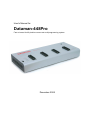
User's Manual for
Dataman-448Pro
Fast universal 4x 48-pindrive concurrent multiprogramming system
December 2005
COPYRIGHT © 2005
Dataman Programmers Ltd
This document is copyrighted by Dataman Programmers Ltd, United Kingdom. All rights reserved.
This document or any part of it may not be copied, reproduced or translated in any form or in any
way without the prior written permission of Dataman Programmers Ltd.
The control program is copyrighted by Dataman Programmers Ltd. The control program or any part
of it may not be analyzed, disassembled or modified in any form, on any medium, for any purpose.
Information provided in this manual is intended to be accurate at the moment of release, but we
continuously improve all our products. Please check for an updated manual on our website at
www.dataman.com.
Dataman Programmers Ltd assumes no responsibility for misuse of this manual.
Dataman Programmers Ltd reserves the right to make changes or improvements to the product
described in this manual at any time without notice. This manual contains names of companies,
software products, etc., which may be trademarks of their respective owners. Dataman
Programmers Ltd respects those trademarks.
ZLI-0298A
2
Table of contents
Introduction .............................................................................................................................. 4
Dataman-448Pro elements.................................................................................................... 6
Manipulation with the programmed device ............................................................................ 6
Selftest and calibration .......................................................................................................... 7
Technical specification........................................................................................................... 7
Setup ....................................................................................................................................... 12
Software setup ..................................................................................................................... 12
Hardware setup ................................................................................................................... 16
Programming a device........................................................................................................... 19
Engineering mode................................................................................................................ 19
Production mode.................................................................................................................. 23
Troubleshooting and warranty.............................................................................................. 27
Troubleshooting ................................................................................................................... 27
If you have an unsupported target device............................................................................ 28
Warranty terms .................................................................................................................... 28
We continuously update our manual. You may find the latest version from our website
(www.dataman.com).
Conventions used in the manual
References to the control program functions are in bold, e.g. Load, File, Device, etc.
References to control keys are written in brackets <>, e.g. <F1>.
Terminology used in the manual:
Device
ZIF socket
Buffer
USB port
HEX data format
any kind of programmable integrated circuits or programmable
devices
Zero Insertion Force socket used for insertion of target device
part of memory or disk, used for temporary data storage
type of port of PC.
format of data file, which may be read with standard text viewers;
e.g. byte 5AH is stored as characters '5' and 'A', which is ASCII
bytes 35H and 41H. One line of this HEX file (one record) contains
start address and data bytes. All records are secured with a
checksum.
3
Introduction
Dataman-448Pro is fast universal 4x 48-pindrive concurrent multiprogramming
system designed for high volume production programming with minimal operator effort.
The chips are programmed at near theoretical maximum programming speed.
Dataman-448Pro supports the silicon technologies of today and tomorrow for
programmable devices without family-specific module. You can be sure the next
devices support require the software update and (if necessary) simple package
converter (programming adapter), therefore the ownership cost are minimized.
Dataman-448Pro provides very competitive price coupled with excellent hardware
design for reliable programming. It is the most cost effective programmer in its class.
Dataman-448Pro consists of four independent isolated universal programming
modules, based on the Dataman-48Pro programmer hardware. Therefore the sockets
can run asynchronously (concurrent programming mode). Each programming module
starts programming as soon as the new chip is correctly inserted to the ZIF of
programming module. It result three programming modules works while you replace the
programmed chip at the fourth. The operator merely removes the finished chip and
inserts a new chip. Operator training is therefore minimized.
Modular construction of hardware - the programming modules works independently allows for continuing operation when a part of the circuit becomes inoperable. It also
makes service quick and easy.
Dataman-448Pro interfaces with the IBM PC/compatible, portable or desktop personal
computers through USB (2.0) port.
Dataman-448Pro provides very fast programming due to high-speed FPGA driven
hardware and execution of time-critical routines inside of the programmer. FPGA based
totally reconfigurable 48 powerful TTL pindrivers provide H/L/pull_up/pull_down and
read capability for each pin of socket. Advanced pindrivers incorporate high-quality
high-speed circuitry to deliver signals without overshoot or ground bounce for all
supported devices. Pin drivers operate down to 1.8V so you'll be ready to program the
full range of today's advanced low-voltage devices.
Dataman-448Pro performs on each programming module device insertion test (wrong
or backward position) and contact check (poor contact pin-to-socket) before it programs
each device. These capabilities, supported by overcurrent protection and signature-byte
check help prevent chip damage due to operator error.
Dataman-448Pro has a built-in protection circuits for eliminate damage of programmer
and/or programmed device due to environment or operator failure. All ZIF socket pins of
Dataman-448Pro programmer are protected against ESD up to 15kV.
4
Dataman-448Pro has the selftest capability, which allows run diagnostic part of
software to thoroughly check the health of the each programming module.
Dataman-448Pro performs programming verification at the marginal level of supply
voltage, which, obviously, improves programming yield, and guarantees long data
retention.
Dataman-448Pro provides a banana jack for ESD wrist straps connection to easy-toimplement the ESD protection control.
Various socket converters are available to handle device in PLCC, SOIC, PSOP,
SSOP, TSOP, TSSOP, TQFP, QFN (MLF), SDIP, BGA and other packages.
It is important to remember that in most cases new devices require only a software
update due to the Dataman-448Pro is truly universal programmer. With our prompt
service, new devices can be easily added. Please contact us for details.
Advanced design including protection circuits, original brand components and careful
manufacturing allows us to provide a three-year warranty on parts and labour for the
Dataman-448Pro (limited 25,000-cycle warranty on ZIF sockets).
Free additional services:
• free lifetime software update via Web site.
Free software updates are available from our
Internet address www.dataman.com.
• AlgOR (Algorithm On Request) service allows you to receive software support for
programming devices not yet available in the current device list.
5
Dataman-448Pro elements
c 48 pin ZIF socket
d LED indicators for work result
e LED indicator power
f Banana jack for connecting ESD wrist strap
g Type B USB connector for PC ↔ Dataman-448Pro communication cable
h Power switch
i Power supply connector
Manipulation with the programmed device
After selection of desired device for your work, you can insert into the open ZIF socket
(the lever is up) and close socket (the lever is down). The correct orientation of the
programmed device in ZIF socket is shown on the picture near ZIF socket on the
6
programmer's cover. The programmed device is necessary to insert into the socket also
to remove from the socket when LED BUSY is off.
Note: Programmer's protection electronics protect the target device and the
programmer itself against either short or long-term power failures. However, it is not
possible to guarantee the integrity of the target device due to incorrect, user-selected
programming parameters. Do not remove the target device from the ZIF socket when
the BUSY LED is on.
Selftest and calibration
If you feel that your programmer does not work properly, please run the programmer
selftest using the Diagnostic POD. The Diagnostic POD is included with the standard
package. For optimal results, we recommend you run the programmer selftest and
calibration every 6 months. See instructions for selftest in the Programmer menu of
PG4UW.
Technical specification
SPECIFICATION (valid for each programming module)
HARDWARE
Base unit, DACs
• USB 2.0 port
• on-board intelligence: powerful microprocessor and FPGA based state machine
• three D/A converters for VCCP, VPP1, and VPP2, controllable rise and fall time
• VCCP range 0..8V/1A
• VPP1, VPP2 range 0..26V/1A
• autocalibration
• selftest capability
• protection against surge and ESD on power supply input, parallel port connection
Socket, pindriver
• 48-pin DIL ZIF (Zero Insertion Force) socket accepts both 300/600 mil devices up to
48-pin
• pindrivers: 48 universal
7
• VCCP / VPP1 / VPP2 can be connected to each pin
• perfect ground for each pin
• FPGA based TTL driver provides H, L, CLK, pull-up, pull-down on all pindriver pins
• analog pindriver output level selectable from 1.8 V up to 26V
• current limitation, overcurrent shutdown, power failure shutdown
• ESD protection on each pin of socket (IEC1000-4-2: 15kV air, 8kV contact)
• continuity test: each pin is tested before every programming operation
DEVICE SUPPORT (valid for each programming module)
Programmer
• EPROM: NMOS/CMOS, 2708, 27xxx and 27Cxxx series, with 8/16 bit data width, full
support for LV series
• EEPROM: NMOS/CMOS, 28xxx, 28Cxxx, 27EExxx series, with 8/16 bit data width
• Flash EPROM: 28Fxxx, 29Cxxx, 29Fxxx, 29BVxxx, 29LVxxx, 29Wxxx, 49Fxxx series,
from 256Kbit to 32Mbit, with 8/16 bit data width, full support for LV series
• Serial E(E)PROM: 24Cxxx, 24Fxxx, 25Cxxx, 45Dxxx, 59Cxxx, 25Fxxx, 25Pxxx, 85xxx,
93Cxxx, NVM3060, MDAxxx series, full support for LV series
• Configuration (EE)PROM: XCFxxx, XC17xxxx, XC18Vxxx, EPCxxx, AT17xxx, 37LVxx
• 1-Wire E(E)PROM: DS1xxx, DS2xxx
• PROM: AMD, Harris, National, Philips/Signetics, Tesla, TI
• NV RAM: Dallas DSxxx, SGS/Inmos MKxxx, SIMTEK STKxxx, XICOR 2xxx, ZMD
U63x series
• PLD: Altera: MAX 3000A, MAX 7000A, MAX 7000B, MAX 7000S, MAX7000AE
• PLD: Lattice: ispGAL22V10x, ispLSI1xxx, ispLSI1xxxEA, ispLSI2xxx, ispLSI2xxxA,
ispLSI2xxxE, ispLSI2xxxV, ispLSI2xxxVE, ispLSI2xxxVL, LC4xxxB/C/V/ZC, M4-xx/xx,
M4A3-xx/xx, M4A5-xx/xx, M4LV-xx/xx
• PLD: Xilinx: XC9500, XC9500XL, XC9500XV, CoolRunner XPLA3, CoolRunner-II
• other PLD: SPLD/CPLD series: AMI, Atmel, AMD-Vantis, Gould, Cypress, ICT, Lattice,
NS, Philips, STM, VLSI, TI
• Microcontrollers 48 series: 87x41, 87x42, 87x48, 87x49, 87x50 series
• Microcontrollers 51 series: 87xx, 87Cxxx, 87LVxx, 89Cxxx, 89Sxxx, 89LVxxx, all
manufacturers, Philips LPC series
• Microcontrollers Intel 196 series: 87C196 KB/KC/KD/KT/KR/...
• Microcontrollers Atmel AVR: AT90Sxxxx, ATtiny, ATmega series
• Microcontrollers Cypress: CY8Cxxxxx
• Microcontrollers ELAN: EM78Pxxx
• Microcontrollers MDT 1xxx and 2xxx series
• Microcontrollers Microchip PICmicro: PIC10xxx, PIC12xxx, PIC16xxx, PIC17Cxxx,
PIC18xxx, dsPIC series
• Microcontrollers Motorola (Freescale): 68HC05, 68HC08, 68HC11 series
• Microcontrollers Myson MTV2xx, 3xx, 4xx and 5xx series
• Microcontrollers National: COP8xxx series
• Microcontrollers NEC: uPD78xxx series
• Microcontrollers Scenix (Ubicom): SXxxx series
• Microcontrollers SGS-Thomson: ST6xx, ST7xx, ST10xx series
• Microcontrollers TI: MSP430 and MSC121x series
• Microcontrollers ZILOG: Z86/Z89xxx and Z8xxx series
• Microcontrollers other: EM Microelectronic, Fujitsu, Goal Semiconductor, Hitachi,
Holtek, Princeton, Macronix, Winbond, Infineon(Siemens), NEC, Samsung, Toshiba, ...
8
Notes:
• For all supported devices see actual Device list on our website www.dataman.com
Package support
• support all devices in DIP with default socket
• package support includes DIP, SDIP, PLCC, JLCC, SOIC, SOP, PSOP, SSOP,
TSOP, TSOPII, TSSOP, QFP, PQFP, TQFP, VQFP, QFN (MLF), SON, BGA, EBGA,
FBGA, VFBGA, UBGA, CSP, SCSP etc.
• support devices in non-DIP packages up to 48 pins with universal adapters
• programmer is compatible with third-party adapters for non-DIP support
Programming speed
Notes:
• It is important to know, we always use random numbers pattern for programming
speed testing. Some our competitors use "sparse" pattern, where only few nonBlank data are programmed or are there are used data with only few 0 bits (FE, EF,
etc.). This cheating approach can "decrease" programming time considerable. If you
plan to compare, ask always which pattern they use.
• The programming speed depends on PC speed only slightly.
Device
M50FW080 (parallel Flash)
AM29DL323DB (parallel Flash)
AM29DL640 (parallel Flash)
AT45D081 (serial Flash)
AT89C51RD2 (microcontroller)
PIC18F452 (microcontroller)
Conditions:
Size [bits]
100000Hx8 (8 Mega)
208000Hx16 (32 Mega)
400080Hx16 (64 Mega)
108000Hx8 (16 Mega)
10000Hx8
4000Hx16
Operation
programming and verify
programming and verify
programming and verify
programming and verify
programming and verify
programming and verify
Time B
32 sec
38 sec
76 sec
43 sec
15 sec
4 sec
P4, 2,4GHz, USB 2.0, Windows XP, 2.18 version of SW
SOFTWARE
• Algorithms: only manufacturer approved or certified algorithms are used. Custom
algorithms are available at additional cost.
• Algorithm updates: software updates are available approx. every 2 weeks, free of
charge.
• Main features: revision history, session logging, on-line help, device and algorithm
information
Device operations
• engineering mode
• standard:
• intelligent device selection by device type, manufacturer or typed fragment of part
name
• automatic ID-based selection of EPROM/Flash EPROM
• blank check, read, verify
• program
• erase
• configuration and security bit program
• illegal bit test
9
• checksum
• security
• insertion test, reverse insertion check
• contact check
• ID byte check
• special
• production mode (automatic start immediately after device insertion)
• auto device serial number increment
• statistic
• count-down mode
• production mode
All operations are controlled by project file.
• standard:
• blank check, read, verify
• program
• erase
• configuration and security bit program
• illegal bit test
• checksum
• security
• insertion test, reverse insertion check
• contact check
• ID byte check
• special
• production mode (automatic start immediately after device insertion)
• auto device serial number increment
• statistic
• count-down mode
Buffer operations
Only for engineering mode.
• view/edit, find/replace
• fill/copy, move, byte swap, word/dword split
• checksum (byte, word)
• print
Supported file formats
• unformatted (raw) binary
• HEX: Intel, Intel EXT, Motorola S-record, MOS, Exormax, Tektronix, ASCII-spaceHEX
• Altera POF, JEDEC (ver. 3.0.A), e.g. from ABEL, CUPL, PALASM, TANGO PLD,
OrCAD PLD, PLD Designer ISDATA, etc.
SPECIFICATION (Dataman-448Pro multiprogramming
system)
• 4x universal programming module (4x 48-pin DIL ZIF sockets)
• operation result LEDs, LED power
10
• USB 2.0 port
• Line power input 100-240VAC/60W max.
• banana jack for ESD wrist straps connection
PC system requirements
•Microsoft Windows 2000/XP/2003/XP64 (XP and above recommended)
•PC Pentium 4; 1.3 GHz (2GHz and above recommended)
•256 MB of RAM (512MB and above recommended)
•50 MB of free disk space (*1)
•USB port 2.0 (2.0 high-speed recommended)
Note (*1): Free disk space requirement depends also on used IC device size. For large
devices the required free space on disk will be approximately 60MB + Device size
GENERAL
• operating voltage AC 100-240V, max.1.2A, 50-60Hz
• power consumption max. 60W active
• dimensions 506x213x86 mm (19.9x8.4x3.4 inch)
• weight (programmer) 4.8kg (10.58 lbs)
• temperature 5°C ÷ 40°C (41°F ÷ 104°F)
• humidity 20%..80%, non condensing
Package included
Standard accessories
• Dataman-448Pro programmer
• USB connection cable PC-programmer
• diagnostic POD for selftest of the programmer (1x)
• anti-dust cover for ZIF socket (4x)
• user manual
• software CD
• calibration test report
• transport case
Bonus pack:
• ESD wrist strap with cord and banana plug
• Vacuum pen
• Gift (surprise)
Additional services
• AlgOR
• free technical support (phone/fax/e-mail).
• free lifetime software update via Web site.
11
Setup
The programmer package contains a CD with the control program, useful utilities and
additional information. Permission is granted to freely copy the CD in order to
demonstrate how the programmer works.
We recommended install software before connecting programmer to PC to avoid
unwanted complication during installation.
Software setup
Insert delivered CD to your CD drive and install program starts automatically (if not, run
setup.exe). Install program will guide you through the installation process and will do all
the necessary steps before you can first run the control program.
Step 1.
Click on “Software installation PROGRAMMERS” button.
Step 2.
Select language and than click on “OK” button.
12
Step 3.
Click on “Next” button
Step 4.
For change default folder click on “Browse” button, select the destination folder.
Then click on “Next” button
13
Step 5.
For change default folder click on “Browse” button, select the destination folder.
Then click on “Next” button
Step 6.
Check if “Install Multiprogramming control support” is selected. Change default
setting, if you want. Then click on “Next” button
14
Step 7.
Check your setting and then click on “Install” button
Step 8.
Installation process will start.
15
Step 8.
Click “Finish” button to finish setup.
New versions of programmer software
In order to exploit all the capabilities of programmer we recommend using the latest
version of PG4UW. You may download the latest version of programmer software (file
PG4UWARD.exe) from our Internet site www.dataman.com, part download.
Copy PG4UWARD.exe to a temporary directory, disconnect Dataman-448Pro from PC
and then launch it. Setup will start with Step 2 from previous chapter.
Hardware setup
Step 1.
Directly connect USB cable to type B USB port on programmer.
Step 2.
Directly connect USB cable to type A USB2.0 port on PC (high-speed recommended).
Step 3.
Connect connectors of power supply cable to appropriate connectors on programmer
and wall plug.
Step 4.
Turn on programmer. At this time all 'work result' LEDs light up successive and then
LEDs switch off.
16
Step 5.
Windows will start with “Found new hardware wizard”.
For Windows XP, Service Pack 2 users only:
Select “No, not this time” and then click on “Next” button.
For all:
Select “Install the software automatically” and then click on “Next” button.
17
Step 6.
Click on “Continue Anyway” button.
Step 7.
Click “Finish” button to finish setup.
Step 8.
“Found new hardware wizard” will launch for each programming module, it mean 4
times. Hardware setup will be continued with Step 5.
Note: If a different USB port on the PC is used for the next connection of Dataman448Pro, “Found new hardware wizard” will launch and install new USB drivers.
18
Programming a device
Dataman-448Pro can operate in two modes:
Engineering mode
Production mode
for make a project
for mass production
Engineering mode
This part of the software is focused to the quick and easy preparation of the project file
for usage in the production mode control software.
Each programming module is driven by an easy-to-use control program with pull-down
menu, hot keys and on-line help. Selecting of device is performed by its class, by
manufacturer or simply by typing a fragment of vendor name and/or part number. It is
the same years-proven software, as is used for all other Dataman single-site
programmers. Engineer can use all properties of this software and can make a project
for mass production.
Standard device-related commands (read, blank check, program, verify, erase) are
boosted by some test functions (insertion test, connection check, signature-byte check),
and some special functions (autoincrement, production mode - start immediately after
insertion of chip into socket).
All known data formats are supported. Automatic file format detection and conversion
are doing during loading of file. There is possible to use Jam files (JEDEC standard
JESD-71) and VME files
The rich-featured auto-increment function enables one to assign individual serial
numbers to each programmed device - or simply increments a serial number, or the
function enables one to read serial numbers or any programmed device identification
signatures from a file.
The software also provides a many informations about programmed device. As a
special, the drawing of all available packages is provided. The software provides also
explanation of chip labeling (the meaning of prefixes and suffixes at the chips) for each
supported chip.
19
Make a project
1.
Connect programmer to PC and outlet. Turn programmer on.
2.
3.
Run the control program: double click on
Find Dataman-448Pro Site (programmer): <Ctrl+F> or right click on panel
Programmer
20
In combo box “Programmer” select Dataman-448Pro, Site and then click on “OK”
button.
4.
Select site.
Select desired Dataman-448Pro Site# and then click on “OK” button
5.
Select device: click on
6.
Load data into buffer from file: click on
21
7.
Set Device operation options
8.
Set desired operations with a device and then click on “OK” button
To customize device use menu <Alt+S>
Set desired settings of a device and then click on “OK” button
22
Note: Menu <Alt+S> is depends on a device.
9.
Save project: click on
project etc.
and select destination folder, write a description of
For more details see Help for PG4UW or “User manual for Dataman-48Pro”. Latest
manual you may find it on www.dataman.com part download.
Production mode
This part of the software is focused to the easy monitoring of high-volume production
operations.
Operator-friendly control software (Pg4uwMC) combines many powerful functions with
ease of use. Graphic user interface provide overview of all important activities result
without burden of operator with non-important details.
There is used a project file to control the Dataman-448Pro multiprogramming system.
Project file contains user data, chip programming setup information, chip configuration
data, auto programming command sequence, etc. Therefore the operator error is
minimized, because the project file is normally created and proofed by engineering and
then given to the operator. The optional protected mode can be set for project file to
avoid unwanted changes of the project file.
Each chip may be programmed with different data such as serial number,
configuration and calibration information.
23
Step by step instruction
1.
Connect programmer to PC and outlet. Turn programmer on.
2.
3.
Run the control program: double click on
Search for connected programmer: <Ctrl+F> or Programmer / Search for
programmer.
In combo box “Multiprogramming system” select Dataman-448Pro and
click on “Search” button. After end of successful search click on “Accept”
button to finish Search of programmer.
4.
5.
or File / Load project
Load project: click on
Click on “Connect programmers” button to connect programming modules
to Multiprogramming Control panel.
6.
Select action with device: click on
.
If
desired action is selected, click on “Run” button. Desired action with devices
on all sites will be start. On “Status window” you may see current states of
action with devices on all sites. After end of action with device on “Status
window” will be displayed “Please, insert a new device into socket” for
appropriate site. After insertion of a new device into socket, desired action
with device will be start automatically.
24
7.
8.
9.
For end of work with desired device: click on “Stop ALL” button.
If you want continue with a new project go to step 4.
For end of work with Dataman-448Pro click on “Disconnect programmers”
button and then terminate a program: - <Alt+F4> or File / Exit.
Menu Programmer / Programmer Sites (or by right click on panel “Site #”) allows the
user to show or to hide Site window, refind a programmer site, disconnect site or run
selftest (Selftest plus) procedure for selected site.
Menu Options / Settings allows the user to verify or to change some setting of control
program.
25
On upper part of window is a table with some site properties: allowed or prohibit site,
Serial number, project file for site and programmed device.
If you check “Site #”, then desired site is allowed. If uncheck, then site is disabled.
If you check “Use Site #1 project for all Sites”, then project from Site #1 is the same
for all sites. If uncheck, then all sites can have different project files.
If you check “Automatic YES!”, then automatic start of action with device after insertion
device to ZIF is allowed.
Timer refresh rate defines how often the Pg4uwMC program will request status
information displayed in Status window panel from running PG4UW programs.
For more details see Help for Pg4uwMC software.
26
Troubleshooting and warranty
Troubleshooting
We really want you to enjoy our product. Nevertheless, problems can occur. In such
cases please follow the instructions below.
•
It might be your mistake in properly operating the programmer or its control program
PG4UW.
• Please read carefully all the enclosed documentation again. Probably you will find
the needed answer right away.
• Try to install programmer and PG4UW on another computer. If your system works
normally on the other computer you might have a problem with the first one PC.
Compare differences between both computers.
• Ask your in-house guru (every office has one!).
• Ask the person who already installed programmer.
•
If the problem persists, please call the local dealer, from whom you purchased the
programmer, or call Dataman direct. Most problems can be solved by phone, e-mail
or fax. If you want to contact us by:
• Mail/fax - Copy the "DEVICE PROBLEM REPORT" form and fill it in following the
instructions at the end of the form. Write everything down that you consider being
relevant about the programmer, software and the target device. Send the
completed form by mail or fax to Dataman (fax number in the control program,
menu Help / About) or to your local dealer. If you send the form by fax please
use black ink, a good pen and large letters!
• E-mail - Use "DEVICE PROBLEM REPORT" form from our Internet site and fill it
in following the instructions at the end of the form. Use standard ASCII editor.
Write everything down that you consider being relevant about the programmer,
software and the target device. Send the completed form by e-mail to your local
dealer or to Dataman ([email protected]).
• Phone - Copy "DEVICE PROBLEM REPORT" form and fill it in following the
instructions at the end of the form. Write everything down that you consider being
relevant about the programmer, software and the target device. Send the
completed form by mail or fax to Dataman (fax number in the control program,
menu Help / About) or to your local dealer. If you send the form by fax please
use black ink, a good pen and large letters easily to read. Then call your local
dealer or Dataman's customer support center (phone number in the control
program, menu Help / About). Please keep your manual, the programmer and
the completed "DEVICE PROBLEM REPORT" form (just faxed) available, so that
you can respond quickly to our questions.
If your programmer is diagnosed as defective, consult your local dealer or Dataman
about the pertinent repair center in your country. Please carefully include the
following items in the package:
• defective product
•
27
• completed "DEVICE PROBLEM REPORT" form
• photocopy of a dated proof of purchase
Without all these items we cannot admit your
programmer to repair.
Note:
You may find the "DEVICE PROBLEM REPORT" form at our Internet site
(www.dataman.com).
If you have an unsupported target device
If you need to operate on a target device not supported by the control program for
programmer, please do not despair and follow the next steps:
•
•
Look in the device list of the latest version of the control program on our Internet site
(section Device List, file corresponded to your programmer). Your new target device
might already be included in this version! If yes, download the file PG4UWARD.exe
and install the new version of the control program.
Contact Dataman direct, filling up a "Device Problem Report" form following the
instructions at the end of this form. We may need detailed data sheets of your target
device and, if possible, samples. The samples will be returned to you after we
include your target device in a new version of PG4UW.
Note:
See also AlgOR service at our Internet site (www.dataman.com), section 'Support'
Warranty terms
The manufacturer, Dataman Programmers Ltd, gives a guarantee on failure-free
operating of the programmer and all its parts, materials and workmanship for three-year
(Dataman-448Pro) from the date of purchase. This warranty is limited to 25,000-cycles
on DIL ZIF socket or 10,000-cycles on other ZIF sockets). If the product is diagnosed as
defective, Dataman Programmers Ltd or the authorized repair center will repair or
replace defective parts at no charge. Parts used for replacement and/or whole
programmer are warranted only for the reminder of the original warranty period.
For repair within the warranty period, the customer must prove the date of purchase.
This warranty terms are valid for customers, who purchase a programmer directly from
Dataman company. The warranty conditions of Dataman sellers may differ depending
on the target country law system or Dataman seller’s warranty policy.
The warranty does not apply to products that are of wear and tear or mechanically
damaged. Equally, the warranty does not apply to products opened and/or repaired
and/or altered by personnel not authorized by Dataman, or to products that have been
misused, abused, accidentated or that were improperly installed.
28
For unwarrantable repairs you will be billed according to the costs of replacement
materials, service time and freight. Dataman or its distributors will determine whether
the defective product should be repaired or replaced and judge whether or not the
warranty applies.
Manufacturer:
: Dataman Programmers Ltd
Station Road
Maiden Newton
Dorset
DT2 0AE
United Kingdom
: + 44 0 1300 320719
www.dataman.com, [email protected]
29