1
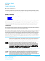
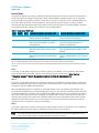
AC4790 User’s Guide Version 2.0 Americas: +1-800-492-2320 Option 2 Europe: +44-1628-858-940 Hong Kong: +852-2923-0610 www.lairdtech.com/ramp AC4790 User’s Manual Version 2.0 REVISION HISTORY Revision 1.0 1.1 Date 2.0 19 Dec 2013 Americas: +1-800-492-2320 Option 2 Europe: +44-1628-858-940 Hong Kong: +852 2923 0610 www.lairdtech.com/ramp Description Initial Release Changes and Revisions Separated Hardware Integration Guide (HIG) from User Guide information (created two separate documents). Add Related Documents section. 2 Laird Technologies AC4790 User’s Manual Version 2.0 CONTENTS Revision History ............................................................................................................................................ 2 AC4790 Transceiver...................................................................................................................................... 4 Overview .................................................................................................................................................... 4 Features ..................................................................................................................................................... 4 Theory of Operation .................................................................................................................................... 5 Masterless Architecture .............................................................................................................................. 5 Modes of Operation ................................................................................................................................... 5 AC4790 Configuration ................................................................................................................................. 9 AT Commands ........................................................................................................................................... 9 On-the-Fly Control Commands .............................................................................................................. 9 Command Descriptions ............................................................................................................................ 11 API Control .............................................................................................................................................. 16 Radio Interface ........................................................................................................................................... 17 Flow Control ............................................................................................................................................ 18 Half Duplex / Full Duplex .......................................................................................................................... 18 System Timing & Latency........................................................................................................................... 19 System Throughput .................................................................................................................................. 19 Random Backoff....................................................................................................................................... 19 Networking ................................................................................................................................................ 20 Max Power ............................................................................................................................................... 20 Security ....................................................................................................................................................... 21 Spread Spectrum History ...................................................................................................................... 21 How Spread Spectrum Works .............................................................................................................. 21 Frequency Hopping Spread Spectrum .................................................................................................. 21 AC4790 Security Features .................................................................................................................... 22 EEPROM Parameters .................................................................................................................................. 23 Ordering Information ................................................................................................................................ 26 Product Part Number Tree ........................................................................................................................ 26 Developer Kit Part Numbers ..................................................................................................................... 26 Appendix I: API Network Topologies ....................................................................................................... 27 API ........................................................................................................................................................... 27 Polling Network ................................................................................................................................... 27 Receive API .......................................................................................................................................... 28 Time Division Multiple Access Network ................................................................................................ 31 Related Documents and Files .................................................................................................................... 32 Americas: +1-800-492-2320 Option 2 Europe: +44-1628-858-940 Hong Kong: +852 2923 0610 www.lairdtech.com/ramp 3 Laird Technologies AC4790 User’s Manual Version 2.0 AC4790 TRANSCEIVER The compact AC4790 900MHz transceiver replaces miles of cable in harsh industrial environments. Using field-proven FHSS technology, which needs no additional FCC licensing in the Americas, OEMs can easily make existing systems wireless with little or no RF expertise. Overview The AC4790 is a member of Laird’s RAMP OEM transceiver family. The AC4790 is a cost effective, high performance, frequency hopping spread spectrum (FHSS) transceiver designed for integration into OEM systems operating under FCC part 15.247 regulations for the 900 MHz ISM band. AC4790 transceivers operate in a masterless architecture. When an AC4790 has data to transmit, it enters transmit mode and starts transmitting a sync pulse intended for an individual radio or broadcasts to all transceivers within the same network and range. Intended receivers synchronize to this sync pulse, a session begins, and data is transmitted. This instinctive dynamic peer-to-peer networking architecture enables several transceiver pairs to carry on simultaneous conversations on the same network. To boost data integrity and security, the AC4790 uses Laird’s FHSS technology featuring optional Data Encryption Standards (DES). Fully transparent, these transceivers operate seamlessly in serial cable replacement applications. Communications include both system and configuration data via an asynchronous TTL serial interface for OEM host communications. Configuration data is stored in an on-board EEPROM and most parameters can be changed on the fly. All frequency hopping, synchronization, and RF system data transmission/reception is performed by the transceiver, transparent to the OEM host. This document contains information about the software interface and configuration of a Laird AC4790 transceiver. Refer to the AC4790 Hardware Integration Guide for hardware interface information. The OEM is responsible for ensuring the final product meets all appropriate regulatory agency requirements listed herein before selling any product. Note: Unless mentioned specifically by name, the AC4790 modules are referred to as the radio or transceiver. Individual naming is used to differentiate product-specific features. The host (any device to which the AC4790 is connected, such as a PC) are referred to as OEM host. Features Networking and Security Easy to Use Masterless: True peer-to-peer, point-to-multipoint, point-to-point Retries and acknowledgements API commands to control packet routing and acknowledgement on a packet-by-packet basis FHSS for security and interference rejection Customizable RF Channel number and system ID Hardware Protocol Status monitoring Two generic input and output digital lines and integrated ADC functions Americas: +1-800-492-2320 Option 2 Europe: +44-1628-858-940 Hong Kong: +852 2923 0610 www.lairdtech.com/ramp 4 Continuous 76.8 kbps RF stream rate Software selectable interface baud rates from 1200 bps to 115.2 kbps Low cost, low power, and small size ideal for high volume, portable and battery powered applications All modules are qualified for Industrial temperatures (-40 °C to 80 °C) Advanced configuration available using AT commands Laird Technologies AC4790 User’s Manual Version 2.0 THEORY OF OPERATION Masterless Architecture The masterless architecture is a true peer-to-peer architecture, where any module that has data to transmit will initiate a communication session with a transceiver(s) within its range/network, transmit data, and exit the session. This architecture eliminates the need for a master which dictates network area and synchronizes radios in the network to allow peer-to-peer communication. Modes of Operation The AC4790 has three different operating modes: Transmit mode Receive mode Command mode If the transceiver is not communicating with another radio, it will be in Receive mode actively listening for a sync pulse from another transceiver. If the radio hears a pulse and determines that it is a broadcast or addressed sync pulse, it will respond by going into session with the sending radio. A transceiver will enter Transmit or Command mode when the OEM host sends data over the serial interface. The state of the Command/Data pin (Pin 17) or the data contents determine which of the two modes will be entered. Transmit Mode All packets sent over the RF are either Addressed or Broadcast packets. Broadcast and Addressed delivery can be controlled dynamically with the API Control byte and corresponding on-the-fly commands. Unicast Only can be enabled to prevent transceivers from receiving broadcast packets. When a radio has data to transmit, it sends out a sync pulse to initiate a session with one or more radios. This 25 ms sync pulse is sent during the first half of each 50 ms hop and transparent to the OEM host. Once a session has been established, the radio transmits the data during the remaining 25 ms of the current hop. The radio will stay in Transmit mode until its session count expires. When sending addressed packets, session count is defined as session count refresh (EEPROM address 0xC4) + number of transmit retries (EEPROM address 0x4C). When sending broadcast packets, session count is equal to session count refresh (EEPROM address 0xC4) + number of broadcast attempts (EEPROM address 0x4D). Once the radio exits the session it returns to the default Receive mode. Addresse d Packets When sending an addressed packet, the RF packet is sent only to the receiver specified in the Destination Address. To increase the odds of successful delivery, Transmit Retries are utilized. Transparent to the OEM host, the transmitting radio will send the RF packet to the remote transceiver. If the remote transceiver receives the packet free of errors, it will return an RF acknowledge to the transmitting radio within the same 50ms hop. If a RF acknowledgement is not received, the transmitting radio will use a transmit retry to resend the packet. The transmitting radio will continue sending the packet until either (1) a RF acknowledgement is received or (2) all transmit retries have been used. The remote transceiver will only send the received packet to the OEM host if and when it is received free of errors. Note: If Transmit Retries is set to 1, the radio will only attempt to send the data one time with no retries, the minimum setting for Transmit Retries is 1 and cannot be set to 0. Broadcast Packets When sending a broadcast packet, the RF packet is sent out to every eligible transceiver on the network. To increase the odds of successful delivery, Broadcast attempts are utilized. Transparent to the OEM host, the transmitting radio sends the RF packet to all remote transceivers that are both in range and network, unless they have Unicast Only enabled. Unlike Transmit Retries, all Broadcast Attempts are used, regardless of when the RF packet is actually received and without RF acknowledgements. If the packet is received on the first attempt, the remote transceiver will ignore the remaining broadcasts. The received packet will only be sent to the OEM host if and when it is received free of errors. Americas: +1-800-492-2320 Option 2 Europe: +44-1628-858-940 Hong Kong: +852 2923 0610 www.lairdtech.com/ramp 5 Laird Technologies AC4790 User’s Manual Version 2.0 Receive Mode If a transceiver detects a sync pulse, addressed to itself or broadcast on its network, while in Receive Mode, it will join the Session and begin receiving data. While in Receive Mode, subsequent data of up to 128 bytes can be received every hop (50 ms). When a transceiver is in Session, its Session Count is decremented by one every hop. When the Session Count reaches zero, the transceiver exits the Session. In order to continue receiving data, the transceivers update their Session Count every time data or an RF acknowledge is received. The SLock0 and SLock1 settings control Session Count as shown below. Table 1: Session Count Truth Table Case Slock0 Slock1 Transceiver Receiving an Addressed Packet Transceiver Receiving a Broadcast Packet 1 0 0 Radio loads its Current Session Count with its Session Count Refresh Radio loads its Current Session Count with its Session Count Refresh 2 0 1 Radio loads its Current Session Count with (its Transmit Retries + its Session Count Refresh) Radio loads its Current Session Count with (its broadcast attempts + its Session Count Refresh) 3* 1 0 Radio loads its Current Session Count with the remote radio’s Session Count Refresh Radio loads its Current Session Count with the remote radio’s Session Count Refresh 4 1 1 Radio loads its Current Session Count with the remote radio’s Current Session Count Radio loads its Current Session Count with the remote radio’s Current Session Count * EEPROM Default. This may not be the best setting for all applications. If having issues use Case 4. Note 1: For Broadcast/Addressed packets, the Session Count for Full Duplex is 2x the value of Session Count in Half Duplex. Note 2: It is best to have all transceivers with the same Session Count Refresh (EEPROM Address 0xC4) value. Session Count Refresh must not be set to 0x00. Case 1 In this case, a radio loads its Session Count with its Session Count Refresh. This is suitable for Half Duplex communication where immediate response is not expected from the remote radio. Note: The term “immediate response” refers to the application layer and not the RF acknowledgment. Case 2 In this case, a radio loads its Session Count with (its Session Count Refresh + its Transmit Retries). This case is suitable for applications where there are high levels of interference and it is likely that transmit retries will be necessary to maintain reliable communications. When an addressed packet or a response to a broadcast packet is sent, the sending radio will listen for a successful acknowledgement. If an acknowledgement is not sent, the radio will resend the packet until either an acknowledgement is received or it has exhausted all available transmit retries. If two radios are on the last hop of the current session and a retry is required, it is possible that once the current session has ended the receiving radio could go into session with a different radio and miss the final packet of the previous session. Adding the radios Transmit retries to its Current Session Count will ensure that the radio does not exit the session when the remote radio is using a Transmit Retry. Case 3 In this case a radio loads its Session Count with the remote radio's Session Count Refresh. This is suitable for full duplex applications as the Session is extended as long as there is communication. Note: This is the default case with which the radio ships and may not work well for all applications. Use Case 4 when a large number of data packets are lost during operation. Americas: +1-800-492-2320 Option 2 Europe: +44-1628-858-940 Hong Kong: +852 2923 0610 www.lairdtech.com/ramp 6 Laird Technologies AC4790 User’s Manual Version 2.0 Case 4 In this case, a radio loads its Session Count with the remote radio's current Session Count. This is suitable for daisy chain applications and large networks in which radios cannot stay in session longer than needed. This case guarantees that two radios will stay in session as long as they have data to communicate and will both leave the session at the same time. Figure 1: Pending RF data in buffer flow Americas: +1-800-492-2320 Option 2 Europe: +44-1628-858-940 Hong Kong: +852 2923 0610 www.lairdtech.com/ramp 7 Laird Technologies AC4790 User’s Manual Version 2.0 Command Mode A radio will enter Command Mode when data is received over the serial interface from the OEM host and either the Command/Data pin (pin 17) is logic Low or the received data contains the “AT+++” (Enter AT Command Mode) command. Once in Command Mode, all data received by the radio is interpreted as command data. Command Data can be either EEPROM Configuration or On-The-Fly commands. Figure 2: Pending Serial data in buffer flow Americas: +1-800-492-2320 Option 2 Europe: +44-1628-858-940 Hong Kong: +852 2923 0610 www.lairdtech.com/ramp 8 Laird Technologies AC4790 User’s Manual Version 2.0 AC4790 CONFIGURATION The AC4790 can be configured using the CC Configuration commands. The CC commands can be issued using either Hardware or Software Configuration. To use Hardware Configuration, Pin 17 of a transceiver must be asserted Low. Software Configuration can be used by entering AT Command Mode before issuing the CC commands. The flowchart in Figure 3 illustrates the configuration process. Figure 3: AC4790 Configuration Flow AT Commands The AT Command mode implemented in the AC4790 creates a virtual version of the Command/Data pin. The “Enter AT Command mode” command asserts this virtual pin Low (to signify Command mode) and the “Exit AT Command mode” command asserts this virtual pin High (to signify Data mode). Once this pin has been asserted Low, all on-the-fly CC commands documented in the manual are supported. On-the-Fly Control Commands The AC4790 transceiver contains static memory that holds many of the parameters that control the transceiver operation. Using the “CC” command set allows many of these parameters to be changed during system operation. Because the commands write to static memory, these parameters will revert back to the settings stored in the EEPROM when the transceiver is reset. While in CC Command mode using pin 17 Americas: +1-800-492-2320 Option 2 Europe: +44-1628-858-940 Hong Kong: +852 2923 0610 www.lairdtech.com/ramp 9 Laird Technologies AC4790 User’s Manual Version 2.0 (Command/Data), the RF interface of the transceiver is still active. Therefore, it can receive packets from remote transceivers while in CC Command mode and forward these to the OEM host. While in CC Command mode using AT commands, the RF interface of the transceiver is active, but packets sent from other transceivers will not be received. The transceiver uses Interface Timeout/RF Packet Size to determine when a CC command is complete. Therefore, there should be no delay between each character as it is sent from the OEM host to the transceiver or the transceiver will not recognize the command. If the OEM host has sent a CC command to the transceiver and an RF packet is received by the transceiver, the transceiver will send the CC command response to the OEM host before sending the packet. However, if an RF packet is received before the Interface Timeout expires on a CC command, the transceiver will send the packet to the OEM host before sending the CC command response. When an invalid command is sent, the radio scans the command to see if it has a valid command followed by bytes not associated with the command. If so, the radio discards the invalid bytes and accepts the command. Otherwise, the radio returns the first byte of the invalid command back to the user and discards the rest. Table 2: Command Quick Reference Command Name Command (all bytes in hex) Return (all bytes in hex) Enter AT Command mode Exit AT Command mode Status Request 0x41 0x54 0x2B 0x2B 0x2B 0x0D 0xCC 0x43 0x4F 0x4D 0xCC 0x41 0x54 0x4F 0x0D - 0xCC 0x44 0x41 0x54 0xCC 0x00 0x00 - - - 0xCC Change Channel Broadcast Packets Write Destination Address Read Destination Address Auto Destination 0xCC 0xCC 0x01 0x08 - 0xCC 0xCC 0xCC 0x10 Byte 6 0xCC 0xCC 0x11 New Channel 0x00: Broadcast 0x01: Addressed Byte 4 of Byte 5 Dest. MAC - - 0xCC 0xCC 0x15 Read API Control Write API Control Read Digital Inputs 0xCC 0xCC 0xCC 0x16 0x17 0x20 Read ADC 0xCC 0x21 Firmware 0x00 Version 0x03 New Channel 0x00 or 0x01 Byte 4 of Byte 5 Byte 6 Dest. MAC Byte 4 of Byte 5 Byte 6 Dest. MAC bit-0: Auto Destination bits-1-7: 0 API Control API Control bit-0: GI0 bit-1: GI1 MSB of 10 LSB of 10 bit bit ADC ADC Write Digital Outputs Set Max Power Enter Probe 0xCC 0x23 0xCC 0xCC 0x25 0x8E Read Temp. EEPROM Byte Read 0xCC 0xCC EEPROM Byte Write Soft Reset bit-0: Auto Destination bit-4: Enable Auto Destination API Control - 0xCC - 0xCC - 0xCC 0xA4 0xC0 0x01: AD In 0x02: Temp 0x03: RSSI bit-0: GO0 bit-1: GO1 New Max Power 0x00: Enter Probe 0x01: Exit Probe Start Address Length 0xCC 0xC1 Start Address Length 0xCC 0xFF - - Americas: +1-800-492-2320 Option 2 Europe: +44-1628-858-940 Hong Kong: +852 2923 0610 www.lairdtech.com/ramp - 10 0xCC 0xCC 0xCC - - - - Length Data Data bit-0: GO0 bit-1: GO1 0xCC Max Power 0xCC 0x00 or 0x01 0xCC Temp (C) 0xCC Starting Address Starting Address Length - - - Data written - - - Laird Technologies AC4790 User’s Manual Version 2.0 Command Descriptions Enter AT Command Mode Prior to sending this command, the OEM host must ensure that the transceiver’s RF transmit buffer is empty. If the buffer is not empty, the radio will interpret the command as data and it will be sent over the RF. This can be accomplished by waiting up to one second between the last packet and the AT command. Command: 0x41 0x54 0x2B 0x2B 0x2B 0x0D Number of Bytes Returned: 4 Response: 0xCC 0x43 0x4F 0x4D Exit AT Command Mode The OEM host should send this command to exit AT Command mode and resume normal operation. Command: 0xCC 0x41 0x54 0x4F 0x0D Number of Bytes Returned: 4 Response: 0xCC 0x44 0x41 0x54 Firmware Version Request The OEM host issues this command to request the firmware of the transceiver. Command: 0xCC 0x00 0x00 Number of Bytes Returned: 3 Response: 0xCC Version XX Parameter Range: XX = 0x00 - 0x03 (Ignore) Change Channel The OEM host issues this command to change the channel of the transceiver. Command: 0xCC 0x01 Channel Number of Bytes Returned: 2 Response: 0xCC Channel Broadcast Packets The OEM host issues this command to change the transceiver operation between Addressed Packets and Broadcast Packets. If Addressed Packets are selected, the transceiver will send all packets to the transceiver designated by the Destination Address programmed in the transceiver. If Broadcast Packets are selected, the transceiver will send its packets to all transceivers on that network. Setting bit-7 of API Control to 1 can also enable Broadcast Packets. Command: 0xCC 0x08 Data1 Number of Bytes Returned: 2 Response: 0xCC Data1 Parameter Range: Data1 = 0x00 for Addressed, 0x01 for Broadcast Americas: +1-800-492-2320 Option 2 Europe: +44-1628-858-940 Hong Kong: +852 2923 0610 www.lairdtech.com/ramp 11 Laird Technologies AC4790 User’s Manual Version 2.0 Write Destination Address The OEM host issues this command to the transceiver to change the destination address. Note: Only the three least significant bytes of the MAC address are used for packet delivery. Command: 0xCC 0x10 MAC3 MAC2 MAC1 Number of Bytes Returned: 4 Response: 0xCC MAC3 MAC2 MAC1 Parameter Range: 0x00 - 0xFF corresponding to 3 LSB’s of destination MAC Address Read Destination Address The OEM host issues this command to the transceiver to read the destination address. Note: Only the three Least Significant Bytes of the MAC Address are used for packet delivery. Command: 0xCC 0x11 Number of Bytes Returned: 4 Response: 0xCC MAC3 MAC2 MAC1 Parameter Range: 0x00 - 0xFF corresponding to 3 LSB’s of destination MAC Address Auto Destination The Host issues this command to change the Auto Destination setting. When issuing this command, the Auto Destination setting will only be changed if the corresponding enable bit is set (Control1 Parameter, EEPROM address 0x56, bit-4). Command: 0xCC 0x15 Data1 Number of Bytes Returned: 2 Response: 0xCC Data2 Parameter Range: Data1 = Data2 = bit-0: Auto Destination, bit-4: Enable Auto Destination modification; bit-0: New Auto Destination setting, bits 2-7: 0 Read API Control The OEM host issues this command to read the API Control byte. Command: 0xCC 0x16 Number of Bytes Returned: 2 Response: 0xCC API Control Write API Control The OEM host issues this command to write the API Control byte. Command: 0xCC 0x17 Number of Bytes Returned: 2 Response: 0xCC API Control Americas: +1-800-492-2320 Option 2 Europe: +44-1628-858-940 Hong Kong: +852 2923 0610 www.lairdtech.com/ramp 12 Laird Technologies AC4790 User’s Manual Version 2.0 Set Max Power The OEM host issues this command to limit the maximum transmit power emitted by the transceiver. This can be useful to minimize current consumption and satisfy certain regulatory requirements. The radios are shipped at maximum allowable power. Command: 0xCC 0x25 Max Power Number of Bytes Returned: 2 Response: 0xCC Max Power Read Temperature The OEM host issues this command to read the onboard temperature sensor. The transceiver reports the temperature in oC where 0x00 - 0x80 corresponds to 0-80o C and where 0xD8 - 0x00 corresponds to -40-0o C. Command: 0xCC 0xA4 Number of Bytes Returned: 2 Response: 0xCC Temperature Parameter Range: Temperature = 0xD8 - 0x80 Read Digital Inputs The OEM host issues this command to read the state of both digital input lines. Command: 0xCC 0x20 Number of Bytes Returned: 2 Response: 0xCC Data1 Parameter Range: Data1 = bit-0: GI0, bit-1: GI1 Read Radio Table The OEM host issues this command to read the Radio Table that resides on the transceiver. The Radio Table stores information for up to the last 8 transceivers that it received a packet from. This information can be useful for determining alternative data paths. Stale Count The Stale Count Reload (0x04) determines the amount of time that a transceiver stays active in the Radio Table. The Stale Count (min: 0x00; max: dependent on EEPROM setting) for a radio is set to 0 when a packet is received; and then incremented by one every 100ms thereafter. When the Stale Count of a transceiver reaches the Stale Count Reload (0x04), the transceiver is considered stale. A Radio Table can hold information for up to 8 different transceivers; however if the table is full and a ninth radio appears, the first stale radio is replaced with the new radio. If none of the radios are stale, the oldest radio is replaced by the new radio. Command: 0xCC 0x18 Number of Bytes Returned: Varies Response: 0xCC #Transceivers MAC2 MAC1 MAC0 RSSI RSSI* StaleCount MAC2 MAC1 MAC0...etc. Table 3: Received Signal Strength RSSI (dBm) -92 -91 -90 -89 -88 -87 -86 -85 Hex Value C0 BC BB B9 B8 AE A9 A2 RSSI (dBm) -71 -70 -69 -68 -67 -66 -65 -64 Americas: +1-800-492-2320 Option 2 Europe: +44-1628-858-940 Hong Kong: +852 2923 0610 www.lairdtech.com/ramp Hex Value 5F 5B 58 54 4F 4B 47 43 13 Laird Technologies AC4790 User’s Manual Version 2.0 RSSI (dBm) -84 -83 -82 -81 -80 -79 -78 -77 -76 -75 -74 -73 -72 Note: Hex Value 92 8D 86 82 7D 79 75 72 6F 6B 68 66 63 RSSI (dBm) -63 -62 -60 -58 -56 -54 -52 -50 -48 -46 -44 -42 to -39 -36 to -22 Hex Value 3D 2A 25 1A 16 13 11 0E 0D 0C 0B 0C 0B The RSSI becomes saturated at levels above -40 dBm and does not follow the curve. Read ADC The OEM host issues this command to read any of the three onboard 10-bit A/D converters. Because the RF is still active in on-the-fly Command mode, the transceiver will not process the command until there is no activity on the network. The Read RSSI command is therefore useful for detecting interfering sources but will not report the RSSI from a remote transceiver on the network. The equations for converting these 10 bits into analog values are as follows: Analog Voltage (10 𝑏𝑖𝑡𝑠 / 0𝑥3𝐹𝐹) ∗ 3.3𝑉 o Temperature ( C) ((𝐴𝑛𝑎𝑙𝑜𝑔 𝑉𝑜𝑙𝑡𝑎𝑔𝑒 − 0.3) / 0.01) − 30 RSSI value (dBm) −105 + (0.22 ∗ (0𝑥3𝐹𝐹 − 10 𝑏𝑖𝑡𝑠)) Command: 0xCC 0x21 Data1 Number of Bytes Returned: 3 Response: 0xCC Data2 Data3 Parameter Range: Data1 = 0x00: AD In 0x01: Temperature 0x02: RSSI Data2 = MSB of requested 10-bit ADC value Data3 = LSB of requested 10-bit ADC value Write Digital Outputs The OEM host issues this command to write both digital output lines to particular states. Note: This command should only be used when Protocol Status (0xC2) is not set to 0xE3. Command: 0xCC 0x23 Data1 Number of Bytes Returned: 2 Response: 0xCC Data1 Parameter Range: Data1 = bit-0: GO0, bit-1: GO1 Americas: +1-800-492-2320 Option 2 Europe: +44-1628-858-940 Hong Kong: +852 2923 0610 www.lairdtech.com/ramp 14 Laird Technologies AC4790 User’s Manual Version 2.0 Probe Enabling bit-6 of API Control will enable this command. When the OEM host issues this command, the transceiver sends out a query every 500 ms. The transceivers, upon receiving the query, randomly choose a query to respond to. After responding to a Probe, the transceiver will wait at least 10 seconds before responding to another probe. Apart from the transceiver response, there are two other responses that provide crucial information to the OEM host. This information can be used to monitor the network and determine alternate routing paths. Command: 0xCC 0x8E Data1 Number of Bytes Returned: 2 Response: 0xCC Data1 Parameter Range: 0x00 = Disable Probe 0x01 = Enable Probe Probe Report Remote transceiver’s response to its OEM host upon receiving a Probe query. Note: Only valid when Probe Report (address 0xC9) is set to 0xE3. Command: N/A Number of Bytes Returned: 5 Response: 0x86 RSSI MAC3 MAC2 MAC1 Parameter Range: MAC3 MAC2 MAC1 = 3 LSB’s of radio sending the Probe query Transceiver’s Response Upon hearing the remote transceiver’s probe acknowledge, the transceiver responds to the OEM host. Command: N/A Number of Bytes Returned: 6 Response: 0x87 RSSI RSSI* MAC3 MAC2 MAC1 Parameter Range: RSSI = How strong remote heard local transceiver RSSI* = How strong local heard remote transceiver EEPROM Byte Read Upon receiving this command, a transceiver will respond with the desired data from the addresses requested by the OEM host. Command: 0xCC 0xC0 Data1 Data2 Number of Bytes Returned: 4+ Response: 0xCC Data1 Data2 Data3 Parameter Range: Data1 = EEPROM address Data2 = Length (0x00 - 0x80) Data3 = Requested data Americas: +1-800-492-2320 Option 2 Europe: +44-1628-858-940 Hong Kong: +852 2923 0610 www.lairdtech.com/ramp 15 Laird Technologies AC4790 User’s Manual Version 2.0 EEPROM Byte Write Upon receiving this command, a transceiver will write the data byte to the specified address but will not echo it back to the OEM host until the EEPROM write cycle is complete (up to 10ms). Multiple byte writes of up to 128 bytes are allowed. An EEPROM boundary exists between addresses 0x7F and 0x80. No single EEPROM write command shall write to addresses on both sides of that EEPROM boundary. Command: 0xCC 0xC1 Data1 Data2 Number of Bytes Returned: 4+ Response: 0xCC Data1 Data2 Data Parameter Range: Data1 = EEPROM address Data2 = Length (0x00 - 0x80) Data3 = Data written Reset The OEM host issues this command to perform a soft reset of the transceiver. Any transceiver settings modified by CC commands will revert to the values stored in the EEPROM. Command: 0xCC 0xFF Number of Bytes Returned: None Response: None API Control API Control is a powerful feature that the masterless protocol offers. When enabled, the API Transmit Packet, API Send Data Complete, and API Receive Packet features provide dynamic packet routing and packet accounting ability to the OEM host, thereby eliminating the need for extensive programming on the OEM host side. These abilities make the masterless protocol ideal for any legacy system. API operation utilizes specific packet formats, specifying various vital parameters used to control radio settings and packet routing on a packet-by-packet basis. The API features can be used in any combination that suits the OEM’s specific needs. API Receive Packet By default, the source MAC is not included in the received data string sent to the OEM host. For applications where multiple radios are sending data, it may be necessary to determine the origin of a specific data packet. When API Receive Packet is enabled, all packets received by a transceiver include the MAC address of the source radio as well as an RSSI indicator which helps determine the link quality between the transceivers. API Receive Packet is enabled when bit-0 of the API Control byte is enabled. Upon receiving a packet the radio sends its OEM host the packet in the following format: 0x81 Note: Payload Data Length (0x01 - 0x80) RSSI RSSI* Source MAC (2,1,0) Payload Data When both API Send Data Complete and API Receive Packet are enabled, the Send Data Complete is received before the transceiver sees the Receive API packet. This order may get reversed when the API Send Data Complete is missed and is resent after the API Receive Packet is received. Americas: +1-800-492-2320 Option 2 Europe: +44-1628-858-940 Hong Kong: +852 2923 0610 www.lairdtech.com/ramp 16 Laird Technologies AC4790 User’s Manual Version 2.0 API Transmit Packet API Transmit Packet is a powerful command that allows the OEM host to send data to a single or multiple (broadcast) transceivers on a packet-by-packet basis. This can be useful for many applications, including polling and/or mesh networks. Refer to the API section for further details. API Transmit Packet is enabled when bit-1 of the API Control byte is enabled. The OEM host should use the following format to transmit a packet over the RF. 0x81 Payload Data Length Session Count Transmit Retries/ Destination Payload Data (0x01 - 0x80) Refresh Broadcast Attempts MAC (2,1,0) 1. If the OEM host does not encode the header correctly, the transceiver will send the entire string (up to 0x80 bytes) and will look for the header in the next data. 2. Although the 7 bytes of overhead are not sent over the RF, they are kept in the buffer until the packet is sent. Keep this in mind so as not to overrun the 256-byte buffer. 3. Setting the MAC to 0xFF 0xFF 0xFF will broadcast the packet to all available transceivers. API Send Data Complete API Send Data Complete can be used as a software acknowledgement indicator. When a radio sends an addressed packet, it looks for a received acknowledgement (transparent to OEM host). If one is not received, the packet will be retransmitted until one is received or all retries have been used. For applications where data loss is not an option, the OEM host may wish to monitor the acknowledgement process using the API Send Data Complete. If an acknowledgement is not received (Failure), the OEM host can send the packet to the transceiver once again. API Send Data Complete is enabled when bit-2 of the API Control byte is enabled. The transceiver sends the OEM host the following data upon receiving an RF acknowledge or exhausting all attempts. 0x82 RSSI RSSI* 0x00: Failure 0x01: Success RADIO INTERFACE Interface Timeout (EEPROM address 0x58), in conjunction with RF Packet Size (EEPROM address 0x5B), determines when a buffer of data will be sent out over the RF as a complete RF packet, based on whichever condition occurs first. Interface Timeout specifies a maximum byte gap between consecutive bytes. When that byte gap is exceeded, the bytes in the transmit buffer are sent out over the RF as a complete packet. Interface Timeout is adjustable in 0.5ms increments and has a tolerance of ±0.5ms. Therefore, the Interface Timeout should be set to a minimum of 2. The default value for Interface Timeout is 0x04 (2ms) and should be adjusted accordingly when changing the transceiver baud rate. RF Packet Size – When the number of bytes in the transceiver transmit buffer equals RF Packet Size, those bytes are sent out as a complete RF packet. It is much more efficient to send a few large packets rather than several short packets as every packet the transceiver sends over the RF contains extra header bytes which are not included in the RF Packet Size. RF packet size can be set to a maximum of 0x80 and must be set to a minimum of 0x06 in order to send the Enter AT Command mode command. Americas: +1-800-492-2320 Option 2 Europe: +44-1628-858-940 Hong Kong: +852 2923 0610 www.lairdtech.com/ramp 17 Laird Technologies AC4790 User’s Manual Version 2.0 Flow Control Flow control refers to the control of data flow between transceivers. It is the method used to handle data in the transmit/receive buffer and determines how data flow between the transceivers is started and stopped. Often, one transceiver is capable of sending data much faster than the other can receive and flow control allows the slower device to tell the faster device when to pause and resume data transmission. When a transceiver has data to send, it sends a Ready-To-Send signal and waits for a Clear-To-Send response from the receiving unit. If the receiving radio is ready to accept data it will assert its CTS Low. CTS will be reasserted when the buffer contains the number of bytes specified by CTS_OFF (EEPROM address 0x5D). These signals are sent apart from the data itself on separate wires. Tip: Can I implement a design using just Txd, Rxd and Gnd (Three-wire Interface)? Yes. However, it is strongly recommended that your hardware monitor the CTS pin of the radio. CTS is taken High by the radio when its interface buffer is getting full. Your hardware should stop sending at this point to avoid a buffer overrun (and subsequent loss of data). You can perform a successful design without monitoring CTS. However, you need to take into account the amount of latency the radio adds to the system, any additional latency caused by Transmit Retries or Broadcast Attempts, how often you send data, non-delivery network timeouts, and interface data rate. Polled type networks, where the Server host requests data from the client host and the client host responds, are good candidates for avoiding the use of CTS. This is because no one transceiver can monopolize the RF link. Asynchronous type networks, where any radio can send to another radio at any point in time, are much more difficult to implement without the use of CTS. Half Duplex / Full Duplex When Half Duplex communication is chosen, the AC4790 sends a packet over the RF whenever it can. This can cause packets sent by multiple transceivers at the same time to collide with each other over the RF. To prevent this, Full Duplex communication can be chosen. Full Duplex shares the bandwidth intelligently to enable two-way collision-free communication. The transceiver calculates the amount of time until the next hop, determines if there is time to send the packet, and sends the packet if possible. If not, the transceiver waits until its next appropriate hop. The radio which initiates the session transmits during the even-numbered hops while the remaining radio(s) will transmit during the odd-numbered hops. Although the RF hardware is still technically Half Duplex, sharing the bandwidth makes the transceiver seem Full Duplex. Enabling Full Duplex mode can cause overall throughputs to be cut in half. Americas: +1-800-492-2320 Option 2 Europe: +44-1628-858-940 Hong Kong: +852 2923 0610 www.lairdtech.com/ramp 18 Laird Technologies AC4790 User’s Manual Version 2.0 SYSTEM TIMING & LATENCY Take care when selecting transceiver architecture, as it can have serious effects on data rates, latency, and overall system throughput. The importance of these three characteristics will vary from system to system and should be a strong consideration when designing the system. Tip: In High-density applications, what amount of latency should be expected? It is not easy to predict the exact amount of latency in high-density applications. There are many variables that affect system latency. The three variables that most affect the latency are the network load, the distance between transceivers, and whether the transceivers are operating in a broadcast or addressed mode. There is no fixed answer as to how much latency will be introduced in the system when considering high-density applications. In these cases we can only offer qualitative analysis of the latency in high-density applications. As the network load increases, then the number of collisions that will occur increases. As the number of collisions increase, then the system latency increases. As the distance between the transceivers increases, so does the system latency. Finally, when transceivers operate in addressed mode they will retry sending a packet up to the number of time specified in the transmit retry parameter specified in the EEPROM. As the number of retries increases, the system latency will also increase. System Throughput When operating as shown in Table 4, an AC4790 can achieve the listed throughput. However, in the presence of interference or at longer ranges, the transceiver may be unable to meet the specified throughput. Table 4: Maximum System Throughput RF Status Radio not in continuous session Radio continuously in session Half Duplex Throughput 25 kbps 45 kbps Full Duplex Throughput each way 12.5 kbps 22.5 kbps Random Backoff The AC4790 uses Carrier Sense Multiple Access (CSMA) protocol with random backoff and a selectable backoff seed. In a packet collision, the AC4790 backs off and retries the packet. When two transceivers detect a collision, each chooses a random number of packet times that it waits before retrying. This number is selected from a pool of numbers defined by the backoff seed and consists of a number between 1 and 2, 1 and 4, 1 and 8, 1 and 16, 1 and 32, 1 and 64, 1 and 128 and 1 and 256. In a very dense network, where many transceivers could experience a collision, it is important to have a higher random backoff seed. Tip: What effects will Random Backoff have on system latency? As the random backoff value increases, the overall system latency increases. Worst case latency (Half Duplex) = 50ms * Number of retries * Max. random value Worst case latency (Full Duplex) = 100ms * Number of retries * Max. random value Americas: +1-800-492-2320 Option 2 Europe: +44-1628-858-940 Hong Kong: +852 2923 0610 www.lairdtech.com/ramp 19 Laird Technologies AC4790 User’s Manual Version 2.0 NETWORKING System ID - System ID (EEPROM address 0x76) is similar to a password character or network number and makes network eavesdropping more difficult. A transceiver will not establish a session or communicate with a transceiver operating on a different System ID or Channel Number. RF Channel Number - Channels 0x00 - 0x0F and 0x30 - 0x37 hop on 26 different frequencies. Channels 0x10 - 0x2F use 50 different frequencies. Table 5: RF Channel Number Settings Channel Set1 RF Channel # Range (0x40) 0x00 - 0x0F Frequency Details & Regulatory requirements 902 - 928 MHz (26 hop bins) Countries US / Canada 0 (AC4790 - 1x1 AC4790 - 200) 0x10 - 0x2F 902 - 928 MHz (50 hop bins) US / Canada 1 (AC4790 - 1x1 AC4790 - 1000) 0x30 - 0x37 915 - 928 MHz (22 hop bins) US / Canada (-1x1 / -200) 2 (AC4790 - 1x1 Australia(-1x1/-200/-1000) AC4790 - 200 AC4790 - 1000) 1. All channels in a Channel Set use the same frequencies in a different order. DES (Data Encryption Standard) - DES encryption is the process of encoding an information bit stream to secure the data content. The DES algorithm is a common, simple and well-established encryption routine. An encryption key of 56 bits is used to encrypt the packet. The receiver must use the exact same key to decrypt the packet; otherwise the data will be garbled. To enable DES, EEPROM Byte 0x45, bit 6 must be set to a value of 1. To disable DES, set bit 6 to a value of 0. The 7 byte (56 bits) Encryption/Decryption Key is located in EEPROM Bytes 0xD0 – 0xD6. It is highly recommended that this Key be changed from the default. Max Power Max Power allows control of the RF output power of the AC4790. Output power and current consumption can vary by as much as ±10% per transceiver for a particular Max Power setting. Contact Laird for assistance in adjusting Max Power. Note: The max power is set during production and may vary slightly from one transceiver to another. The max power can be set as low as desired but should not be set higher than the original factory setting. A backup of the original power setting is stored in EEPROM address 0x8E. Americas: +1-800-492-2320 Option 2 Europe: +44-1628-858-940 Hong Kong: +852 2923 0610 www.lairdtech.com/ramp 20 Laird Technologies AC4790 User’s Manual Version 2.0 SECURITY The 4790 product family utilizes a Frequency Hopping Spread Spectrum (FHSS) technology, which provides the foundation for secure digital wireless communications. The purpose of this section is to take a brief look at how spread spectrum technology works and explain how an OEM can enable specific security features available in the AC4790. Spread Spectrum History Spread Spectrum (or SS signals) dates back to World War II, when a female German scientist was granted a patent on a simple frequency hopping continuous wave (CW) system. The allies also experimented with spread spectrum in World War II. These early research and development efforts tried to provide countermeasures for radar, navigation beacons and communications. The U.S. Military has used SS signals over satellites for at least 25 years. How Spread Spectrum Works SS radio communications has long been a favorite technology of the military because it resists jamming and is hard for an enemy to intercept. And now, this very same technology is being widely used in the commercial, industrial and even consumer markets. The reason: SS signals are distributed over a wide range of frequencies and then collected onto their original frequency at the receiver, making them so inconspicuous as to be transparent. Just as they are unlikely to be intercepted by a military opponent, so are they unlikely to interfere with other signals intended for business and consumer users – even ones transmitted on the same frequencies. Spread signals are intentionally made to be much wider band than the information they are carrying and use special pseudo noise codes to make them more noise-like. It is this very characteristic that makes SS signals difficult to detect, intercept and demodulate. SS signals are hard to detect on narrowband equipment because the signal's energy is spread over a much wider bandwidth. Further, SS signals are harder to jam (interfere with) than narrowband signals and have a much lower probability to be intercepted, which is why the military has used spread spectrum for so many years. The spread of energy over a wide band makes SS signals less likely to interfere with narrowband communications. Narrowband communications, conversely, cause little to no interference to SS systems because the receiver effectively integrates the signal over a wide bandwidth to recover it. Besides being hard to intercept and jam, spread spectrum signals are hard to exploit or imitate. Signal exploitation is the ability of a non-network member to listen in to a network and use information from the network without being a valid network member or participant. Imitation is the act of falsely or maliciously introducing false traffic or messages into a network. SS signals are also naturally more secure than narrowband radio communications. Thus SS signals can be made to have any degree of message privacy that is desired. Messages can also be encrypted to any level of secrecy desired. The very nature of SS allows military or intelligence levels of privacy and security with minimal complexity. While these characteristics may not be very important to everyday business or consumer needs, these features are important to understand. Frequency Hopping Spread Spectrum A FHSS radio does just what its name implies – that is, it “hops” from frequency to frequency over a wide band. The specific order in which frequencies are occupied is a function of a code sequence, and the rate of hopping from one frequency to another is a function of the information rate. Americas: +1-800-492-2320 Option 2 Europe: +44-1628-858-940 Hong Kong: +852 2923 0610 www.lairdtech.com/ramp 21 Laird Technologies AC4790 User’s Manual Version 2.0 AC4790 Security Features As mentioned at the beginning of this section, the AC4790 uses FHSS technology. In addition, Laird has implemented three levels of security in the AC4790. All three levels of security are associated with their own EEPROM parameter that can programmed for permanent operation or be changed during system operation in volatile memory. The first two levels of security must be configured to establish a network of transceivers and are defined as the Channel Number and System ID. The Channel Number represents a specific hopping sequence and provides physical separation between collocated networks. Thus, all transceivers in a network must be programmed to the same Channel Number. There are a total of 48 Channel Numbers. System ID is similar to a password character or network number and makes network eavesdropping more difficult. A receiving radio will not go in range of or communicate with another radio on a different System ID. There are a total of 256 System ID values. If FHSS technology, Channel Number and System ID are still not enough to secure your data, the AC4790 supports the Data Encryption Standard (DES), which is the third level of security. Encryption is the process of encoding an information bit stream to secure the data content. The algorithm described in this standard specifies both encrypting and decrypting operations which are based on a binary number called a key. A key of 56 bits is used to encrypt and decrypt the data. The encryption algorithm specified in this standard is commonly known among those using the standard. The unique key chosen for use in a particular application makes the results of encrypting data using the algorithm unique. Selection of a different key causes the encrypted data that is produced for any given set of inputs to be different. The cryptographic security of the data depends on the security provided for the key used to encrypt and decrypt the data. Data can be recovered from the encrypted data only by using exactly the same key used to encrypt it. Unauthorized recipients of the encrypted data who know the algorithm but do not have the correct key cannot derive the original data algorithmically. However, anyone who does have the key and the algorithm can easily decrypt the encrypted data and obtain the original data. Thus, a standard algorithm based on a secure key provides a basis for exchanging encrypted data by only issuing the encryption key to authorized recipients. Americas: +1-800-492-2320 Option 2 Europe: +44-1628-858-940 Hong Kong: +852 2923 0610 www.lairdtech.com/ramp 22 Laird Technologies AC4790 User’s Manual Version 2.0 EEPROM PARAMETERS The OEM host can program various parameters that are stored in EEPROM which become active after a power-on reset. Table 6 gives the locations and descriptions of the parameters that can be read/written by the OEM host. Factory default values are also shown. Do not write to any EEPROM addresses other than those listed in Table 6. Do not copy one transceiver’s EEPROM to another transceiver as doing so may cause the transceiver to malfunction. Table 6: EEPROM Parameters Length (Bytes) 40 Range Product ID EEPROM Address 0x00 Stop Bit Delay 0x3F 1 0x00 0xFF 0xFF Channel Number 0x40 1 0x00 0x37 1x1: 0x00 200: 0x00 1000: 0x10 Baud Rate Low 0x42 1 0xFC Baud Rate High 0x43 1 0x00 0xFF 0x00 Control 0 0x45 1 Transmit Retries 0x4C 1 Broadcast Attempts 0x4D 1 Stale Count Reload 0x4F 1 Parameter Americas: +1-800-492-2320 Option 2 Europe: +44-1628-858-940 Hong Kong: +852 2923 0610 www.lairdtech.com/ramp Default 0x00 0x00 0x01 0xFF 0x01 0xFF 0x10 0x01 0xFF 0x40 0x04 23 Description 40 bytes - Product identifier string. Includes revision information for software/hardware. For systems employing RS485 interface or Parity, the stop bit might come too early. Stop bit delay controls the width of the last bit before the stop bit occurs. 0xFF = Disable Stop Bit Delay (12 us) 0x00 = (256 * 1.6 us) + 12 us 0x01 - 0xFE = (value * 1.6 us) + 12 us Set 0 = 0x00 - 0x0F (US/Canada): 1x1/200 Set 1 = 0x10 - 0x2F (US/Canada): 1x1/1000 Set 2 = 0x30 - 0x37 (US/Canada): 1x1/200; Australia: 1x1/200/1000 Low byte of the interface baud rate. Default baud rate is 57600 bps. High byte of interface baud. Always 0x00 Settings are: bit-7: 0 bit-6: DES Enable 0 = Disable 1 = Enable bits 5-0: 0 Maximum number of times a packet is sent out when Addressed packets are selected. Maximum number of times a packet is sent out when Broadcast packets are selected. Determines the amount of time that a transceiver will keep a radio active in its Receive Table. This value is reset every time a packet is received from that radio. Laird Technologies AC4790 User’s Manual Version 2.0 EEPROM Address 0x56 Length (Bytes) 1 Range Interface Timeout 0x58 1 0x02 0xFF 0x04 RF Packet Size 0x5B 1 0x80 CTS On 0x5C 1 0x01 0x80 0x01 0xFF CTS Off 0x5D 1 0x00 0xFE 0xAC Max Power 0x63 1 0x00 0x60 Parity 0x6F 1 0xE3, 0xFF Set in Production & can vary 0xFF Destination ID 0x70 6 System ID 0x76 1 RS485 DE 0x7F 1 0x00 0xFF 0x00 0xFF 0xE3, 0xFF MAC ID 0x80 6 Original Max Power 0x8E 1 Parameter Control 1 Americas: +1-800-492-2320 Option 2 Europe: +44-1628-858-940 Hong Kong: +852 2923 0610 www.lairdtech.com/ramp Default Description 0x43 Settings are: bit-7: Laird Use Only bit-6: Laird Use Only bit-5: Laird Use Only bit-4: Auto Destination 0 = Use destination address 1 = Use auto destination bit-3: Laird Use Only bit-2: RTS Enable 0 = Ignore RTS 1 = Transceiver obeys RTS bit-1: Duplex 0 = Half Duplex 1 = Full Duplex bit-0: Auto Config 0 = Use EEPROM values 1 = Auto Configure values Specifies a byte gap timeout, used in conjunction with RF Packet Size to determine when a packet coming over the interface is complete (0.5ms per increment). Used in conjunction with Interface Timeout; specifies the maximum size of an RF packet. CTS will be deasserted (High) when the transmit buffer contains at least this many characters. Once CTS has been deasserted, CTS will be reasserted (Low) when the transmit buffer is contains this many or fewer characters. Used to increase/decrease the output power. The transceivers are shipped at maximum allowable power. 0xE3 = Enable Parity 0xFF = Disable Parity Note: Enabling parity cuts throughput and the interface buffer size in half. Specifies destination for RF packets 0xD2 0x01 0xFF 0x00 0xFF Set in production, may vary 24 Similar to network password. Radios must share a system ID to talk with each other. 0xE3 = GO0 is active Low DE for control of external RS485 hardware 0xFF = Disable RS485 DE Factory programmed unique IEEE MAC address. Copy of original max power EEPROM setting. This address may be referenced but should not be modified. Laird Technologies AC4790 User’s Manual Version 2.0 Product ID EEPROM Address 0x90 Length (Bytes) 15 API Control 0xC1 1 Protocol Status 0xC2 1 Session Count Refresh 0xC4 1 Random BackOff 0xC3 1 Parameter Americas: +1-800-492-2320 Option 2 Europe: +44-1628-858-940 Hong Kong: +852 2923 0610 www.lairdtech.com/ramp Range Default 0x10 0x00 0xFF 0x00 0xFF 0xE3 0x00 0xFF 0x00 0x08 25 Description 0x90 - 0x93: Product ID 0x94 - 0x95: Prefix (CL or AC) 0x96 - 0x99: Power (200M, 200A, 1000, 1x1) Note: There will be a period in front of the 1x1 to keep the field at four bytes 0x9A - 0x9C: Interface (232, 485, TTL) 0x9D - 0x9E: Setup script (01 is stock) 0x9F: Reserved for future use; always 0xFF Settings are: bit-7: Broadcast packets 0 = Addressed Packets 1 = Broadcast Packets bit-6: Probe 0 = Disable Probe 1 = Enable Probe bit-5: SLock1 0 = Disable 1 = Enable bit-4: SLock0 0 = Disable 1 = Enable bit-3: Unicast Packets 0 = Broadcast or Addressed delivery 1 = Addressed packets only bit-2: Send Data Complete Enable 0 = Disable 1 = Enable bit-1: API Transmit Packet Enable 0 = Disable 1 = Enable bit-0: API Receive Packet Enable 0 = Disable 1 = Enable Determines if the GO0 & GO1 server as generic output or as protocol status. Specifies the number of hops a transceiver stays in session with another transceiver The random amount of time a transceiver waits when a collision occurs before resending the packet again. 0x00: Disable Random Backoff 0x01: Wait 1-2 packet times, then retry 0x03: Wait 1-4 packet times, then retry 0x07: Wait 1-8 packet times, then retry 0x0F: Wait 1-16 packet times, then retry 0x1F: Wait 1-32 packet times, then retry 0x3F: Wait 1-64 packet times, then retry 0x7F: Wait 1-128 packet times, then retry 0xFF: Wait 1-256 packet times, then retry Laird Technologies AC4790 User’s Manual Version 2.0 Length (Bytes) 1 Range Default Description Sense Adjust EEPROM Address 0xC8 0x00 0xFF Probe Report 0xC9 1 0x00 0xFF Set in production, may vary 0xE3 DES Key 0xD0 7 0x00 0xFF The minimum RSSI required by a transceiver to establish a session upon hearing a long beacon. When set to 0xE3, upon receiving a probe the transceiver sends a Probe Report to the OEM host. 56-bit Data Encryption key Parameter ORDERING INFORMATION Product Part Number Tree Figure 4: Product part number tree Developer Kit Part Numbers All of the above part numbers can be ordered as a development kit by prefacing the part number with “SDK”. As an example, part number AC4790-200A can be ordered as a development kit using the part number: SDK-AC4790-200A. All developer’s kits include (2) transceivers, (2) development boards, (2) 7.5V DC unregulated power supplies, (2) serial cables, (2) USB cables, (2) antennas, configuration/testing software and integration engineering support Americas: +1-800-492-2320 Option 2 Europe: +44-1628-858-940 Hong Kong: +852 2923 0610 www.lairdtech.com/ramp 26 Laird Technologies AC4790 User’s Manual Version 2.0 APPENDIX I: API NETWORK TOPOLOGIES API The API feature set of the AC4790 provides powerful packet routing capabilities to the OEM host. The number of API configurations is endless as individual radios can all be configured differently to suit the OEM host’s varying needs. Some of the most common implementations are described in the following pages. Polling Network Many applications require multiple locations to report back to a single access point. One solution is to enter Command mode, change the transceiver’s destination address and then exit Command mode to resume normal operation. When it is time to communicate with another transceiver, the process is repeated; costing time and inevitably reduction in throughput as unnecessary commands are issued. As an alternative, the Transmit API command can be used to control packet routing on a packet-by-packet basis. Figure 5: A sample polling network The simplest implementation consists of a smart Shared Access Point (SAP) with a microcontroller or processor of some type which has Transmit API enabled. The SAP controls which transceiver(s) each packet is routed. Broadcast packets should be used when all remotes are to receive the same message and addressed packets when communication with a single remote only is desired. An example of each is shown in the following pages. Addressed Transmit API 1. To poll radio 1, the SAP transmits the packet using the following format: Americas: +1-800-492-2320 Option 2 Europe: +44-1628-858-940 Hong Kong: +852 2923 0610 www.lairdtech.com/ramp 27 Laird Technologies AC4790 User’s Manual Version 2.0 2. To poll radio 2, the SAP transmits the packet using the following format: 3. This continues until all radios have successfully been polled by the SAP. Broadcast Transmit API To send out a universal poll request or data packet, the OEM may wish to utilize the broadcast portion of the Transmit API command. The Broadcast command is similar to the addressed command; only with the Destination MAC Address set to all 0xFF. The remote response is dependent on the OEM’s specific needs and equipment. In many cases, remote radios are connected to dumb devices without the intelligence to filter out or append specific portions of a packet that is transmitted or received. Since the 7 bytes of overhead in the Transmit API command are not sent over the RF, the remotes will receive only the payload data, “STATUS”. If auto destination is enabled on the remote radio, the transceiver will automatically change its destination address to that of the radio it last received a packet from. When the remote device sends its response, it will therefore automatically be routed back to the SAP. Depending on the API configuration of the SAP, the packet will be received in one of two formats: Receive API When Receive API is enabled, the transceiver will receive the reply data + the MAC address of the source radio and two RSSI values; RSSI is how strong the remote transceiver heard the local transceiver and RSSI* is how strong the local heard the remote transceiver. Americas: +1-800-492-2320 Option 2 Europe: +44-1628-858-940 Hong Kong: +852 2923 0610 www.lairdtech.com/ramp 28 Laird Technologies AC4790 User’s Manual Version 2.0 It may be useful to the OEM host to determine which radio each packet originated from. When Receive API is enabled, every packet received by the transceiver will be received in the above format. Normal Receive Mode (non – API) If Receive API is not enabled, the transceiver will receive the reply data only (i.e. “ALLGOOD”) from each transceiver. Daisy Chain / Repeater Network For applications spanning long distances and cases where the desired radio is not within range of the sending radio, a daisy chain type network can be implemented. With the use of API commands, a processor and external buffer, a daisy chain or repeater can easily be implemented to store and forward the data to the desired radio. Error! Reference source not found. assumes that radio A has a packet which needs to be received by radio D (far right). Figure 6: Daisy Chain / Repeater Network 1. Radio A transmits the string “FIND D” to Radio B using the Transmit API command. 2. Radio B receives the packet “FIND D”, and stores it in the buffer until the current session with Radio A has ended. Once the current session ends, Radio B forwards the packet from its buffer to Radio C. Americas: +1-800-492-2320 Option 2 Europe: +44-1628-858-940 Hong Kong: +852 2923 0610 www.lairdtech.com/ramp 29 Laird Technologies AC4790 User’s Manual Version 2.0 3. Radio C receives the packet “FIND D”, and stores it in the buffer until the current session with Radio B has ended. Once the current session ends, Radio C forwards the packet from its buffer to Radio D. 4. Radio D receives the packet “FIND D” and sends the appropriate response back down the line to Radio A. Loopback Repeater The simplest repeater to implement is a loopback repeater. A loopback repeater can be created by connecting the transceiver’s RXD and TXD lines together. When the radio receives data, it will retransmit the data to all available transceivers on the network. It is important not to have two loopback repeaters in range of each other as they will continuously transmit data back and forth. Figure 7: Loopback Repeater If radios B & C in the above picture are not within range of radio A, they will not be able to receive or respond to communications from radio A. A loopback repeater can be added between the three such that it is in range of both radio A and radios B & C. When the repeater receives a packet from radio A, it will transmit the packet out to radios B & C. If the repeater is set to Broadcast mode, radio A will receive a copy Americas: +1-800-492-2320 Option 2 Europe: +44-1628-858-940 Hong Kong: +852 2923 0610 www.lairdtech.com/ramp 30 Laird Technologies AC4790 User’s Manual Version 2.0 of each packet that it sends. If the repeater has a specific destination address (i.e. 12 34 A2), then radio A will not receive the packet as its MAC address will not match the specified destination address. Time Division Multiple Access Network For a more intelligent network, a TDMA system can be implemented. In this system, various radios transmit data to a Shared Access Point (SAP) during an assigned time interval. The system is synchronous so that only one radio is transmitting at a time and has full access to the SAP’s bandwidth. In a TDMA network, each radio must store its data for the amount of time between its transmissions or bursts. A typical format for data passing through a SAP is shown in Error! Reference source not found.. A frame consists of arriving bursts from remote radios and each frame is then divided into multiple time slots. The bursts can be of varying lengths and can be longer for heavy-traffic stations. To prevent overlaps, guard intervals can be inserted to absorb small timing errors in burst arrivals. Figure 8: TDMA Timeslots Example: 1. 2. 3. 4. 5. Shared Access Point (SAP) sends broadcast packet which includes a sync pulse Remote radio9s hear the sync pulse and join the session Radio A transmits during time interval t = 1 Radio B transmits during time interval t = 2 Radio N transmits during time interval t = N – 1 This type of implementation requires careful planning and should allow enough time for retries if necessary. When full duplex is enabled, the radio which initiated the session (SAP) will transmit during the even numbered hops and the remote radios will transmit only during odd numbered hops. Americas: +1-800-492-2320 Option 2 Europe: +44-1628-858-940 Hong Kong: +852 2923 0610 www.lairdtech.com/ramp 31 Laird Technologies AC4790 User’s Manual Version 2.0 RELATED DOCUMENTS AND FILES The following additional AC4790 technical documents are also available from the Laird AC4790 product page under the Documentation tab: AC4790 Product Brief AC4790 Hardware Integration Guide Statement of Compliance to EU WEEE Directive and RoHS Directive The following downloads are also available from the Laird RAMP modules Product Information page: Configuration Utility USB Drivers Americas: +1-800-492-2320 Option 2 Europe: +44-1628-858-940 Hong Kong: +852 2923 0610 www.lairdtech.com/ramp 32 Laird Technologies AC4790 User’s Manual Version 2.0 Laird Technologies is the world leader in the design and manufacture of customized, performance-critical products for wireless and other advanced electronics applications. Laird Technologies partners with its customers to find solutions for applications in various industries such as: Network Equipment Telecommunications Data Communications Automotive Electronics Computers Aerospace Military Medical Equipment Consumer Electronics Laird Technologies offers its customers unique product solutions, dedication to research and development, as well as a seamless network of manufacturing and customer support facilities across the globe. CONN-GUIDE-AC4790-v2_0 Copyright © 2013 Laird Technologies, Inc. All rights reserved. The information contained in this manual and the accompanying software programs are copyrighted and all rights are reserved by Laird Technologies, Inc. Laird Technologies, Inc. reserves the right to make periodic modifications of this product without obligation to notify any person or entity of such revision. Copying, duplicating, selling, or otherwise distributing any part of this product or accompanying documentation/software without the prior consent of an authorized representative of Laird Technologies, Inc. is strictly prohibited. All brands and product names in this publication are registered trademarks or trademarks of their respective holders. This material is preliminary. Information furnished by Laird Technologies in this specification is believed to be accurate. Devices sold by Laird Technologies are covered by the warranty and patent indemnification provisions appearing in its Terms of Sale only. Laird Technologies makes no warranty, express, statutory, and implied or by description, regarding the information set forth herein. Laird Technologies reserves the right to change specifications at any time and without notice. Laird Technologies’ products are intended for use in normal commercial and industrial applications. Applications requiring unusual environmental requirements such as military, medical life-support or lifesustaining equipment are specifically not recommended without additional testing for such application. Limited Warranty, Disclaimer, Limitation of Liability Americas: +1-800-492-2320 Option 2 Europe: +44-1628-858-940 Hong Kong: +852 2923 0610 www.lairdtech.com/ramp 33 Laird Technologies