1
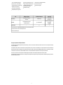
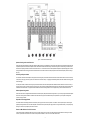
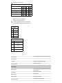
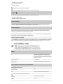
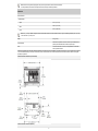
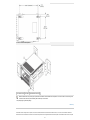
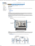
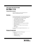
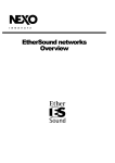
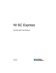
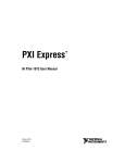
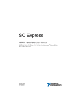
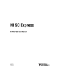
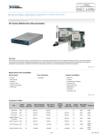
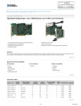
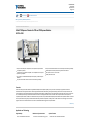
Technical Sales
United States
(866) 531-6285
[email protected]
Print |
E-mail this Page |
Open Document as PDF
Ordering Information | Detailed Specifications
For user manuals and dimensional drawings, visit the product page resources tab on ni.com.
Last Revised: 2011-06-13 09:32:12.0
8-Slot PXI Express Chassis for PXI and PXI Express Modules
NI PXIe-1082
Accepts 3U PXI, PXI Express, CompactPCI, and CompactPCI Express modules
Low-jitter internal 100 MHz reference clock for PXI Express slots with 25 ppm stability
1 PXI Express system slot
Variable speed fan controller optimizes cooling and acoustic emissions
7 peripheral slots: 7 PXI Express compatible, 4 PXI compatible and 1 PXI Express
system timing compatible
Quiet operation for 0 to 30 °C at 43.6 dBA
Remote power-inhibit control
Up to 1 GB/s per-slot dedicated bandwidth (x4 PCI Express), 4 GB/s total system
bandwidth
Low-jitter internal 10 MHz reference clock for PXI slots with 25 ppm stability
Overview
The NI PXIe-1082 eight-slot chassis features a high-bandwidth backplane with PXI Express capability in every slot to meet a wide variety of high-performance test and
measurement and control application needs. It is ideal for high-speed measurements, data streaming, and high-channel-density system solutions. Its compact form factor and
optional portable LCD monitor and keyboard accessory make the NI PXIe-1082 ideal for portable applications. The chassis provides the full power of 507 W across the entire 0 to
55 °C extended temperature range, a feature National Instruments offers on all NI high-performance chassis. The NI PXIe-1082 is compa tible with both PXI Express and
CompactPCI Express modules. In addition, this chassis features four hybrid slots, which provide the added compatibility with standard PXI and CompactPCI modules. The chassis
also incorporates all of the timing and synchronization features defined by the latest PXI specification, including a built-in 10 MHz reference clock, PXI trigger bus, and PXI star
trigger as well as a built-in 100 MHz reference clock, SYNC 100, andPXI differential star triggers for PXI Express modules.
Back to Top
Application and Technology
High Reliability
0 to 55 °C extended temperature range
Multichassis Synchronization
Numerous synchronization options: CLK10
1
Optional Features
Portable LCD monitor and keyboard accessory
0 to 55 °C extended temperature range
Numerous synchronization options: CLK10
sharing, GPS, IEEE 1588, IRIG-B, and so on
Portable LCD monitor and keyboard accessory
NI PXI System Monitor API for power supply,
temperature, and fan monitoring
PXI Express system timing slot for tight
synchronization across chassis
System assurance program
HALT-tested for increased reliability
Switchless CLK10 routing
507 W from 0 to 55 °C without derating
Front and rear rack-mount kits
Field-replaceable power supply shuttle
Slot
Bus Signaling
Bandwidth
PXI Express Peripheral
Hybrid (PXI)
PCI Express (4 x4 links) and
PCI (32/33)
PXI Express System
PCI Express (x4)
PCI (32/33) and
PCI Express (x4)
4 GB/s dedicated for PXI Express
132 MB/s shared for PXI
Up to 1 GB/s dedicated1
1
32
Number of Slots
132 MB/s shared (PXI) or up to 1
GB/s dedicated1
(PXI Express)
4
1
Each slot can have up to 1 GB/s dedicated bandwidth; however, if more than one slot connected
to the same switch is used, 1 GB/s is shared among those slots.
2
Includes one system timing slot.
Slot Types Accept PXI and PXI Express Modules
This chassis enables higher-bandwidth systems and provides the flexibility you need to work with both PXI and PXI Express modules. There are a total of nine PXI Express slots and eight
PXI hybrid-compatible slots.
The PXI Express system slot offers four x4 PCI Express links (1 GB/s single direction per link): one x4 link is connected directly to slot 2 and the other three x4 links are connected to three
switches. Each switch provides a x4 PCI Express link to two peripheral slots. Each slot is capable of 1 GB/s per-direction dedicated bandwidth; however, if you use another slot connected
to the same switch, the slots share the 1 GB/s total bandwidth to the switch. The total system bandwidth is also dependent on the PXI Express controller selected.
There is one x1 PCI Express link to a PCI Express-to-PCI translation bridge on the backplane. The four PXI Express hybrid slots deliver connectivity to either
a x4 PCI Express link or to the 32-bit, 33 MHz PCI bus on the backplane. The PXI Express system timing slot accepts a PXI Express module or a PXI Express system timing controller for
advanced timing and synchronization.
2
Figure 1. NI PXIe-1082 Chassis Backplane
Optimized Cooling and Acoustic Emissions
The NI PXIe-1082 chassis integrates two pulse-width modulation (PWM) system fans to provide filtered, forced-air cooling that exceeds the cooling demands of PXI Express and
CompactPCI Express as well as PXI and CompactPCI modules. The NI PXIe-1082 offers a HIGH fan setting to maximize cooling and an AUTO fan setting to minimize acoustic
emissions when operating the chassis in ambient environments less than 55 °C. The chassis monitors air intake temperature and adjusts fan speed accordingly while the AUTO
setting is selected. With this technology, the NI PXIe-1082 achieves acoustic noise levels as low as 43.6 dBA (sound pressure level measured at operator position according to
ISO 7779).
PXI Timing and Synchronization
For PXI modules, the NI PXIe-1082 backplane is fully compliant with PXI timing and synchronization standards. The chassis includes a 10 MHz reference clock with an accuracy
of ±25 parts per million (ppm), less than 5 ps jitter, and a maximum slot-to-slot skew of 300 ps. For triggering and handshaking needs, the NI PXIe-1082 offers the PXI trigger bus
and PXI star trigger.
For PXI Express modules, in addition to PXI timing and synchronization features, the NI PXIe-1082 backplane offers a differential 100 MHz reference clock with an accuracy of
±25 ppm, less than 3 ps jitter, and a maximum slot-to-slot skew of 100 ps. The chassis also provides a differential star trigger to the PXI Express slots to deliver less than 200 ps
intermodule skew. With the SYNC 100, a peripheral module installed in the NI PXIe-1082 can generate its own CLK10 signal, deriving it from the 100 MHz reference clock.
Software System Configuration
The NI PXIe-1082 chassis is configured with NI Measurement & Automation Explorer (MAX). With this software configuration tool, you can easily configure NI PXIe-1065 systems
without time-consuming manual installation of initialization files. MAX creates the pxisys.ini file that defines the layout and parameters of your PXI system including chassis,
controller, and plug-in modules.
Replaceable Power Supply Shuttle
This chassis include a removable high-performance universal AC power supply with built-in overcurrent protection. An isolated 12 VDC line provides power to the cooling fans,
significantly reducing electrical noise on the chassis backplane. The NI PXIe-1082 incorporates the power supply and fans into a single modular unit that you can replace quickly,
resulting in a mean time to repair (MTTR) of less than five minutes.
External 10 MHz Reference Clock I/O Connectors
An NI PXIe-1082 chassis includes IN/OUT BNC connectors for the 10 MHz reference clock on the rear of the chassis. When the backplane detects a 10 MHz signal on the IN
connector, it phase locks to the external clock. The OUT connector provides a buffered, non-TTL version of the 10 MHz reference clock.
3
The 10 MHz clock may also be driven by an optional system timing controller populated in slot 4. These system timing controllers provide a higher-stability clock source such as
an oven controlled crystal oscillator (OCXO) and the ability to drive the PXI star and PXI Express differential star triggers as well as import or export the various trigger lines on the
backplane.
Remote Power Inhibit and Monitoring
The NI PXIe-1082 chassis features remote power inhibit and voltage monitoring through a DB-9 connector on the rear of the chassis. Use this connector to switch off power or
monitor the power remotely in the chassis.
Power Supply, Temperature, and Fan Monitoring
This chassis continuously monitors power supply voltages, air intake temperature, and fan speeds to ensure safe system operation in the event of an unexpected system event. It
provides feedback to the user via a bicolor LED in the power switch on the front of the chassis, and the chassis makes necessary adjustments to continue operation such as
increase fan speeds if the temperature rises. You can also monitor the status of the NI PXIe-1082 with the included NI PXI System Monitor API.
NI PXIe-1082 Accessories
The NI PXIe-1082 has several optional accessories for complete system integration and optimized chassis functionality. An optional, attachable, and portable LCD monitor and
keyboard accessory and a rugged portable carrying case provide effective portable solutions. Front and rear rack-mount kits are available for 19 in. rack-mounted systems. You
can easily replace spare power supplies with little system downtime because of the modular nature of the NI PXIe-1082 power supply and fan shuttle. You can use slot blockers to
improve the overall cooling performance of the chassis.
Figure 2. NI PMA-1115 Portable Touch Screen LCD Monitor, Keyboard and Touchpad
Accessory Attached to National Instruments Eight-Slot Chassis
Figure 3. NI PXI Carrying Case Accessory
PXI System Assurance Program
With an NI system assurance program, you receive complete system-level assembly and functional testing of the PXI chassis, controller, and all peripheral devices, as well as
installation of all device drivers and software programs (such as NI LabVIEW). For online configuration of a complete PXI system, including information about NI system
assurance programs, visit the PXI Advisor at ni.com/pxiadvisor.
Back to Top
Ordering Information
For a complete list of accessories, visit the product page on ni.com.
Products
Part Number Recommended Accessories
Related Accessories
4
Part Number
PXI Chassis Filler Panel Kit, 3 Double- & 3 Single-Slot Panels
778679-01
No accessories required.
PXI EMC Filler Panel Kit
778700-01
No accessories required.
NI PXI 8-Slot Rear Rack Mount Kit
778643-02
No accessories required.
NI PMA-1115: Portable PXI Monitor and English Keyboard Accessory
780215-01
No accessories required.
Replacement Power Supply and Fan Shuttle for NI PXIe-1082
780322-01
No accessories required.
NI PXI Carrying Case
780398-01
No accessories required.
NI PXI Slot Blocker, Set of 5
199198-01
No accessories required.
NI PXI 8-Slot Front Rack Mount Kit
778643-01
No accessories required.
PXIe-1082
PXIe-1082, 8-Slot 3U PXI Express Chassis
Requires: 1 Cable
780321-01
Cable: Shielded - Power Cord, AC, U.S., 120 VAC, 2.3 meters
763000-01
Cable: Shielded - Power Cord, 240V, 10A, North American
763068-01
Back to Top
Support and Services
System Assurance Programs
NI system assurance programs are designed to make it even easier for you to own an NI system. These programs include configuration and deployment services for your NI PXI,
CompactRIO, or Compact FieldPoint system. The NI Basic System Assurance Program provides a simple integration test and ensures that your system is delivered completely
assembled in one box. When you configure your system with the NI Standard System Assurance Program, you can select from available NI system driver sets and application
development environments to create customized, reorderable software configurations. Your system arrives fully assembled and tested in one box with your software preinstalled.
When you order your system with the standard program, you also receive system-specific documentation including a bill of materials, an integration test report, a recommended
maintenance plan, and frequently asked question documents. Finally, the standard program reduces the total cost of owning an NI system by providing three years of warranty
coverage and calibration service. Use the online product advisors at ni.com/advisor to find a system assurance program to meet your needs.
Technical Support
Get answers to your technical questions using the following National Instruments resources.
Support - Visit ni.com/support to access the NI KnowledgeBase, example programs, and tutorials or to contact our applications engineers who are located in NI sales
offices around the world and speak the local language.
Discussion Forums - Visit forums.ni.com for a diverse set of discussion boards on topics you care about.
Online Community - Visit community.ni.com to find, contribute, or collaborate on customer-contributed technical content with users like you.
Repair
While you may never need your hardware repaired, NI understands that unexpected events may lead to necessary repairs. NI offers repair services performed by highly trained
technicians who quickly return your device with the guarantee that it will perform to factory specifications. For more information, visit ni.com/repair.
Training and Certifications
The NI training and certification program delivers the fastest, most certain route to increased proficiency and productivity using NI software and hardware. Training builds the skills
to more efficiently develop robust, maintainable applications, while certification validates your knowledge and ability.
Classroom training in cities worldwide - the most comprehensive hands-on training taught by engineers.
On-site training at your facility - an excellent option to train multiple employees at the same time.
Online instructor-led training - lower-cost, remote training if classroom or on-site courses are not possible.
Course kits - lowest-cost, self-paced training that you can use as reference guides.
Training memberships and training credits - to buy now and schedule training later.
Visit ni.com/training for more information.
Extended Warranty
NI offers options for extending the standard product warranty to meet the life-cycle requirements of your project. In addition, because NI understands that your requirements may
change, the extended warranty is flexible in length and easily renewed. For more information, visit ni.com/warranty.
5
OEM
NI offers design-in consulting and product integration assistance if you need NI products for OEM applications. For information about special pricing and services for OEM
customers, visit ni.com/oem.
Alliance
Our Professional Services Team is comprised of NI applications engineers, NI Consulting Services, and a worldwide National Instruments Alliance Partner program of more than
600 independent consultants and integrators. Services range from start-up assistance to turnkey system integration. Visit ni.com/alliance.
Back to Top
Detailed Specifications
This appendix contains specifications for the NI PXIe-1082 chassis.
Caution Specifications are subject to change without notice.
Electrical
AC Input
Input voltage rating
100 to 240 VAC
Operating voltage range 1
90 to 264 VAC
Input frequency
50/60 Hz
Operating frequency range
47 to 63 Hz
Input current rating
8-4A
Over-current protection
10 A circuit breaker
Line regulation
<±0.2%
3.3 V
<±0.1%
5V
<±0.1%
±12 V
Efficiency
70% typical
Power disconnect
The AC power cable provides main power disconnect. The front-panel power switch causes the internal chassis power supply to provide
DC power to the CompactPCI/PXI Express backplane. You also can use the rear-panel D-SUB 9-pin connector and power mode switch
to control the internal chassis power supply.
DC Output
DC current capacity (IMP)
Voltage Maximum Current
+3.3 V
32 A
+5 V
27 A
+12 V
32 A
–12 V
2.0 A
5 VAUX
2.0 A
6
Note Maximum total usable power is 420W.
Backplane pin current capacity
Slot
+5 V V (I/O) +3.3 V +12 V –12 V 5 VAUX
System Controller Slot
15 A
System Timing Slot
-
15 A
30 A
-
1A
1A
-
-
6A
4A
-
Hybrid Peripheral Slot with PXI-1 Peripheral
6A
5A
6A
1A
1A
-
Hybrid Peripheral Slot with PXI-5 Peripheral
-
-
6A
4A
-
1A
Notes Total system slot current should not exceed 45 A.
PCI V(I/O) pins in hybrid slots are connected to +5 V.
The maximum power dissipated in the system slot should not exceed 140 W.
The maximum power dissipated in a peripheral slot should not exceed 38.25 W.
Load regulation
Voltage Load Regulation
+3.3 V
<5%
+12 V
<5%
+5 V
<5%
–12 V
<5%
Maximum ripple and noise (20 MHz bandwidth)
Voltage
Maximum Ripple and Noise
+3.3 V
50 mVpp
+12 V
50 mVpp
+5 V
50 mVpp
–12 V
50 mVpp
All outputs protected from short circuit and overload with automatic recovery
Over-current protection
Over-voltage protection
Clamped at 20 to 30% above nominal output voltage
3.3 V and 5 V
Replacement in under 5 minutes
Power supply shuttle MTTR
Chassis Cooling
Forced air circulation (positive pressurization) through three 165 cfm fans with
High/Auto speed selector
Module cooling system
Bottom of module to top of module
Slot airflow direction
Bottom rear of chassis
Module cooling intake
Along both sides and top of chassis
Module cooling exhaust
Forced air circulation through two integrated fans
Power supply cooling system
7
Right side of chassis
Power supply cooling intake
Left side of chassis
Power supply cooling exhaust
Environmental
2,000 m (800 mbar) (at 25 °C ambient)
Maximum altitude
2
Pollution Degree
For indoor use only.
Operating Environment
0 to 55 °C (Tested in accordance with IEC-60068-2-1 and IEC-60068-2-2.
Meets MIL-PRF-28800F Class 3 low temperature limit and MIL-PRF-28800F
Class 2 high temperature limit.)
Ambient temperature range
10 to 90%, noncondensing (Tested in accordance with IEC-60068-2-56.)
Relative humidity range
Storage Environment
Ambient temperature range
–40 to 71 °C (Tested in accordance with IEC-60068-2-1 and IEC-60068-2-2.
Meets MIL-PRF-28800F Class 3 limits.)
Relative humidity range
5 to 95%, noncondensing (Tested in accordance with IEC-60068-2-56.)
Shock and Vibration
Operational shock
30 g peak, half-sine, 11 ms pulse (Tested in accordance with IEC-60068-2-27.
Meets MIL-PRF-28800F Class 2 limits.)
Random Vibration
5 to 500 Hz, 0.3 grms
Acoustic Emissions
Sound Pressure Level (at Operator Position)
(Tested in accordance with ISO 7779. Meets MIL-PRF-28800F requirements.)
Auto fan (up to ~30 °C ambient)
43.6 dBA
High fan
62 dBA
Sound Power
Auto fan (up to ~30 °C ambient)
52.8 dBA
High fan
72 dBA
Note Specifications are subject to change without notice.
Safety
This product is designed to meet the requirements of the following standards of safety for electrical equipment for measurement, control, and laboratory use:
IEC 61010-1, EN 61010-1
UL 61010-1, CSA 61010-1
Note For UL and other safety certifications, refer to the product label or the Online Product Certification section.
Electromagnetic Compatibility
This product is designed to meet the requirements of the following standards of EMC for electrical equipment for measurement, control, and laboratory use:
EN 61326 EMC requirements; Minimum Immunity
EN 55011 Emissions; Group 1, Class A
AS/NZS CISPR 11: Group 1, Class A emissions
8
AS/NZS CISPR 11: Group 1, Class A emissions
FCC 47 CFR Part 15B: Class A emissions
ICES-001: Class A emissions
Note For EMC compliance, operate this device with shielded cables.
Note For the standards applied to assess the EMC of this product, refer to the Online Product Certification section.
CE Compliance
This product meets the essential requirements of applicable European Directives, as amended for CE marking, as follows:
2006/95/EC; Low-Voltage Directive (safety)
2004/108/EC; Electromagnetic Compatibility Directive (EMC)
Online Product Certification
Refer to the product Declaration of Conformity (DoC) for additional regulatory compliance information. To obtain product certifications and the DoC for this product, visit
ni.com/certification, search by module number or product line, and click the appropriate link in the Certification column.
Environmental Management
National Instruments is committed to designing and manufacturing products in an environmentally responsible manner. NI recognizes that eliminating certain hazardous
substances from our products is beneficial not only to the environment but also to NI customers.
For additional environmental information, refer to the NI and the Environment Web page at ni.com/environment. This page contains the environmental regulations and directives
with which NI complies, as well as other environmental information not included in this document.
Waste Electrical and Electronic Equipment (WEEE)
EU Customers At the end of the product life cycle, all products must be sent to a WEEE recycling center. For more information about WEEE recycling centers, National
Instruments WEEE initiatives, and compliance with WEEE Directive 2002/96/EC on Waste Electrical and Electronic Equipment, visit ni.com/environment/weee.htm.
Backplane
3U-sized; one system slot (with three system expansion slots) and 17
peripheral slots. Compliant with IEEE 1101.10 mechanical packaging. PXI
Express Specification compliant. Accepts both PXI Express and CompactPCI
(PICMG 2.0 R 3.0) 3U modules.
Size
UL 94 V-0 Recognized
Backplane bare-board material
Conforms to IEC 917 and IEC 1076-4-101, and are UL 94 V-0 rated
Backplane connectors
System Synchronization Clocks (PXI_CLK10, PXIe_CLK100, PXIe_SYNC100)
10 MHz System Reference Clock: PXI_CLK10
500 ps
Maximum slot-to-slot skew
±25 ppm max. (guaranteed over the operating temperature range)
Accuracy
Note The 10 MHz system reference clock does not require calibration.
5 ps RMS phase-jitter (10 Hz–1 MHz range)
Maximum jitter
45%–55%
Duty-factor
9
Unloaded signal swing
3.3 V ±0.3 V
Note For other specifications refer to the PXI-1 Hardware Specification.
100 MHz System Reference Clock: PXIe_CLK100 and PXIe_SYNC100
100 ps
Maximum slot-to-slot skew
Accuracy
±25 ppm max. (guaranteed over the operating temperature range)
Maximum jitter
3 ps RMS phase-jitter (10 Hz–12 kHz range)
2 ps RMS phase-jitter (12 kHz–20 MHz range)
45%–55%
Duty-factor for PXIe_CLK100
400–1000 mV
Absolute single-ended voltage swing (When each line in the differential pair
has 50 W termination to 1.30 V or Thévenin equivalent)
Note For other specifications refer to the PXI-5 PXI Express Hardware Specification.
External 10 MHz Reference Out (BNC on rear panel of chassis)
Accuracy
±25 ppm max. (guaranteed over the operating temperature range)
Maximum jitter
5 ps RMS phase-jitter (10 Hz–1 MHz range)
Output amplitude
1 VPP ±20% square-wave into 50 Ω
2 VPP unloaded
50 Ω ±5 Ω
Output impedance
External Clock Source
10 MHz ±100 PPM
Frequency
Input amplitude
Rear panel BNC
200 mVPP to 5 VPP square-wave or sine-wave
System timing slot PXI_CLK10_IN
5 V or 3.3 V TTL signal
50 Ω ±5 Ω
Rear panel BNC input impedance
1 ps RMS phase-jitter (10 Hz–1 MHz range)
Maximum jitter introduced by backplane
PXIe_SYNC_CTRL
2.0–5.5 V
VIH
0–0.8 V
VIL
PXI Star Trigger
Maximum slot-to-slot skew
250 ps
Backplane characteristic impedance
65 Ω ±10%
Note For PXI slot to PXI Star mapping refer to the System Timing Slot section of the NI PXIe-1082 User Manual.
For other specifications refer to the PXI-1 Hardware Specification.
PXI Differential Star Triggers (PXIe-DSTARA, PXIe-DSTARB, PXIe-DSTARC)
150 ps
Maximum slot-to-slot skew
25 ps
Maximum differential skew
100 Ω ±10%
Backplane differential impedance
10
Note For PXIe slot to PXI_DSTAR mapping refer to the System Timing Slot section of the NI PXIe-1082 User Manual.
For other specifications, the NI PXIe-1082 complies with the PXI-5 PXI Express Hardware Specification.
Mechanical
Overall dimensions
Standard chassis
Height
6.97 in. (177.1 mm)
Width
10.68 in. (271.4 mm)
18.40 in. (396.5 mm)
Depth
Note 0.57 in. (14.5 mm) is added to height when feet are installed. When tilted with front feet extended on table top, height is increased approximately 2.08 in. (52.8 mm)
in front and 0.583 in. (14.8 mm) in rear.
8.8 kg ( 19.4 lb)
Weight
Chassis materials
Sheet Aluminum (5052-H32, 3003-H14, and 6061-T6), Extruded Aluminum
(6060-T6), and Cold Rolled Steel, PC-ABS, Santoprene, Nylon
Finish
Conductive Clear Iridite on Aluminum, Electroplated Nickel on Cold Rolled
Steel, Polyurethane Enamel
The following two figures show the NI PXIe-1082 chassis dimensions. The holes shown are for the installation of the optional rack mount kits. You can install those kits on the front
or rear of the chassis, depending on which end of the chassis you want to face toward the front of the instrument cabinet. Notice that the front and rear chassis mounting holes
(size M4) are symmetrical.
NI PXIe-1082 Chassis Dimensions (Front and Side)
NI PXIe-1082 Chassis Dimensions (Bottom)
11
NI Chassis Rack Mount Kit Components
1 Front Rack Mount Kit 2 NI Chassis 3 Optional Rear Rack Mount Kit
Note The chassis shown in the previous figure is representative of the NI PXI-1044/1045 and NI PXIe-1082 product line. For more information on rack mounting the NI
PXIe-1082 chassis, refer to the printed installation guide included with your rack mount kit.
1
The operating range is guaranteed by design.
Back to Top
©2010 National Instruments. All rights reserved. CompactRIO, CVI, FieldPoint, LabVIEW, National Instruments, National Instruments Alliance Partner, NI, ni.com, NI-DAQ, and NI TestStand are trademarks of
National Instruments. The mark LabWindows is used under a license from Microsoft Corporation. Windows is a registered trademark of Microsoft Corporation in the United States and other countries. Other product
12
and company names listed are trademarks or trade names of their respective companies. A National Instruments Alliance Partner is a business entity independent from National Instruments and has no agency,
partnership, or joint-venture relationship with National Instruments.
My Profile | RSS | Privacy | Legal | Contact NI © 2011 National Instruments Corporation. All rights reserved.
13