1
Load Monitoring Units
LMU 212 and LMU 217
User’s manual
While every precaution has been exercised in the compilation of this document to ensure
the accuracy of its contents, Magtrol assumes no responsibility for errors or omissions.
Additionally, no liability is assumed for any damages that may result from the use of the
information contained within this publication.
Copyright
Copyright ©2008 Magtrol SA. All rights reserved.
Copying or reproduction of all or any part of the contents of this manual without the express
permission of Magtrol is strictly prohibited.
First Edition, rev. B – September 2014
Revisions To This Manual
The contents of this manual are subject to change without prior notice. Should revisions be necessary, updates to
all Magtrol User’s Manuals can be found at Magtrol’s web site at http://www.magtrol.com/support/manuals.htm
Please compare the date of this manual with the revision date on the web site, then refer to the manual’s Table of
Revisions for any changes/updates that have been made since this edition..
Table of Revisions
Date
Edition
Changes
Section
09/12/2014
First Edition rev. B
Configuration and Calibration Report updated
A.2
07/01/2009
First Edition rev. A
0% hysteresis changed to <0.5%
2.4.4.1 and
2.4.4.2
03 2009
First Edition
-
-
i
Table of Contents
Preface................................................................................................................................................................. iii
Purpose of This Manual.................................................................................................................................................................iii
Who Should Use This Manual.......................................................................................................................................................iii
Manual Organization.....................................................................................................................................................................iii
Revisions To This Manual................................................................................................................................. i
Table of Revisions.......................................................................................................................................................................... i
Table of Contents............................................................................................................................................ ii
Table of Figures.............................................................................................................................................................................iii
1. Introduction.................................................................................................................................................. 1
1.1
1.2
General information......................................................................................................................................................... 1
Data Sheet...................................................................................................................................................................... 2
2. Installation / Configuration................................................................................................................... 7
2.1
2.2
2.3
2.4
General information......................................................................................................................................................... 7
Installation of the LMU 212 and LMU 217 load monitoring units..................................................................................... 7
Connection of the LMU 212 and LMU 217 load monitoring units.................................................................................. 10
Configuration of the Load monitoring Unit..................................................................................................................... 11
2.4.1
2.4.2
2.4.3
2.4.4
2.4.5
2.4.6
2.4.7
2.4.8
2.4.9
Adaptation of the monitor to the available supply unit.................................................................................. 11
Selection of the type of wiring to the strain gauge......................................................................................... 13
Designation of the voltage and current inputs/outputs................................................................................... 14
Configuration of the detection chains............................................................................................................ 14
Selection of the pass band.............................................................................................................................. 19
Selection of the sensitivity range................................................................................................................... 19
Selection of the application............................................................................................................................ 20
Division of the transducer signal or the input voltage Ui/p by two................................................................. 21
Use without transducer................................................................................................................................... 22
3. Calibration................................................................................................................................................... 23
3.1
Electrical calibration (standard)..................................................................................................................................... 23
3.1.1
3.1.2
3.1.3
3.1.4
3.1.5
3.2
Quick Calibration........................................................................................................................................................... 27
3.2.1
3.2.2
3.3
Zero adjustment on the voltage output........................................................................................................... 23
Zero adjustment on the current output........................................................................................................... 24
Sensitivity adjustment on the voltage output................................................................................................. 24
Sensitivity adjustment on the current output.................................................................................................. 24
Adjustment of the detection thresholds.......................................................................................................... 25
Operations preceding a quick calibration....................................................................................................... 27
Calibration procedure..................................................................................................................................... 27
Calibration of the built-in test equipment (B.I.T.E.)........................................................................................................ 28
4. Applications................................................................................................................................................. 29
4.1
Using one or several load monitoring units................................................................................................................... 29
4.1.1
4.1.2
4.1.3
4.2
4.3
Using one single load monitoring unit LMU 212.......................................................................................... 29
Using one single load monitoring unit LMU 217.......................................................................................... 30
Using three load monitoring units LMU 212................................................................................................. 31
Using transducers in parallel......................................................................................................................................... 32
Operational check of the measuring chain ("OK")......................................................................................................... 32
4.3.1
4.3.2
Checking the transducer signal transmission to the load monitoring unit..................................................... 32
“OK” philosophy............................................................................................................................................ 33
ii
Magtrol Load Monitoring Units LMU 212 & 217
4.5
4.6
Table of Contents
Permanent supply check............................................................................................................................................... 33
Using B.I.T.E. signal...................................................................................................................................................... 34
5. Repair.............................................................................................................................................................. 36
5.1Trouble-shooting............................................................................................................................................................ 36
Appendix A :
Configuration and Calibration Report................................................................................................ 37
A.1
A.2
LMU 212........................................................................................................................................................................ 38
LMU 217........................................................................................................................................................................ 39
Appendix B : CE Conformity Declaration.............................................................................................. 41
Magtrol Limited Warranty.......................................................................................................................... 42
Claims42
Table of Figures
2. Installation / Configuration
Fig. 2–1 Installation of the LMU 212 load monitoring unit......................................................................................11
Fig. 2–2 Installation of the LMU 217 load monitoring unit......................................................................................12
Fig. 2–3 Stuffing gland (overall and exploded view).................................................................................................13
Fig. 2–4 Load monitoring unit board with location of the selection elements..........................................................14
Fig. 2–5 Jumper and switch configuration.................................................................................................................15
Fig. 2–6 LMU grounding when using a 230, 115 or 48 VAC supply.........................................................................16
Fig. 2–7 Wiring types.................................................................................................................................................17
Fig. 2–8 Location of the SWA micro-switches...........................................................................................................18
Fig. 2–9 Examples of switching delays......................................................................................................................20
Fig. 2–10 Potentiometer location on the load monitoring unit board.......................................................................21
Fig. 2–11 Location of the SWB micro-switches on the load monitoring unit board..................................................22
Fig. 2–12 Location of the SWC micro-switches on the load monitoring unit board..................................................23
Fig. 2–13 Location of the transducer presence simulation jumpers..........................................................................25
3. Calibration
Fig. 3–1 Location of the potentiometers on the load monitoring unit board.............................................................26
Fig. 3–2 Location of the micro-switches SWC3 and SWC4 on the load monitoring unit board................................28
Fig. 3–3 Location of the relays REL1 and REL2 on the load monitoring unit board................................................29
4. Applications
Fig. 4–1
Fig. 4–2
Fig. 4–3
Fig. 4–4
Fig. 4–5
Fig. 4–6
Using one single load monitoring unit LMU 212........................................................................................32
Using one single load monitoring unit LMU 217........................................................................................33
Using three load monitoring units LMU 212..............................................................................................34
Using one single load monitoring unit LMU 212........................................................................................35
Permanent supply check LED......................................................................................................................36
B.I.T.E. control input terminals...................................................................................................................38
iii
Preface
Purpose of This Manual
This manual has all the necessary information regarding the installation, connection, calibration and
use of Magtrol's LMU 212 and LMU 217 load monitoring unit. To achieve maximum capability
and ensure proper use of the system, please read this manual in its entirety before operating. Keep
the manual in a safe place for quick reference whenever a question should arise.
Who Should Use This Manual
This manual is for users who want to install and use the load monitoring unit LMU 212 or LMU
217 for processing data generated by load measuring pins. The user should have suitable technical
training in mechanics and electronics so as to allow him to install and use this load monitoring unit
without risk.
Manual Organization
This section gives an overview of the structure of the manual and the information contained within it.
Some information has been deliberately repeated in different sections of the document to minimize
cross-referencing and to facilitate understanding through reiteration.
Summary of the different chapters :
Chapter 1 :
Introduction – Contains the technical data sheet of the load monitoring units
LMU 212 and LMU 217 and gives its technical characteristics as well as a brief
overview of the application fields.
Chapter 2 :
Installation / Configuration – Contains the mounting and configuration
explanations for the load monitoring unit LMU 212 or LMU 217.
Chapter 3 :
Calibration – Describes the calibration procedures of the zero, sensitivity
and relays detection level of the load monitoring unit as well as of test signal level
(B.I.T.E.).
Chapter 4 :
Applications – Describes examples of applications for one or several load
monitoring units. Explains the use of the test signal (B.I.T.E.).
Chapter 5 :
REPAIR – Contains solutions to problems encountered with LMU series load
monitoring units.
Appendix A : CONFIGURATION AND CALIBRATION REPORT – Contains the configuration
and calibration report of the LMU 212 and LMU 217 which must be filled in with
great care when installing the load monitoring unit.
Appendix B : CE CONFORMITY DECLARATION – Contains the CE conformity declaration
of the MAGTROL LMU series load monitoring units.
iv
Preface
Magtrol Load Monitoring Units LMU 212 & 217
Warnings
CAUTION
The lightning flash with arrowhead symbol within an equilateral
triangle is intended to alert the user to the presence of uninsulated
dangerous voltage within the product’s enclosure that may be
of sufficient magnitude to constitute a risk of electric shock to persons.
.
RISK OF ELECTROCUTION
WARNING : THE INSTALLATION AND THE CALIBRATION IS RESERVED TO THE
QUALIFIED STAFF. PLEASE CONSULT THIS MANUAL BEFORE ANY MANIPULATION
AND FOLLOW ATTENTIVELY THE INSTRUCTIONS.
The exclamation point symbol within an equilateral triangle is
intended to alert the user to the presence of operating
and maintenance instructions in the literature accompanying
the appliance.
THE CABLING MUST BE DONE WITH POWER SUPPLY SWITCHED OFF.
THE CALIBRATION REQUIRES TO OBSERV SECURIZED ELECTRICAL WORKING
METHODS.
PLEASE PAY ATTENTION IN DESCRIPTIVE PRESENT ON THE DEVICE
Symbols used in this manual
The following symbols and type styles may be used in this manual to highlight certain parts of the text:
Note:
This is intended to draw the operator’s attention to complementary
information or advice relating to the subject being treated. It
introduces information enabling the correct and optimal function
of the product.
Caution:This is used to draw the operator’s attention to information,
directives, procedures, etc. which, if ignored, may result in
damage to the material being used. The associated text describes
the necessary precautions to take and the consequences that
may arise if these precautions are ignored.
WARNING! This introduces directives, procedures,
precautionary measures, etc. which must be
executed or followed with the utmost care
and attention, otherwise the personal safety
of the operator or third party may be at risk.
The reader must absolutely take note of the
accompanying text, and act upon it , before
proceeding further.
v
1. Introduction
1.1General information
The LMU series load monitoring units have been specially designed for applications using load pins
with strain gauge sensors. This range of monitoring units offer a large flexibility for the implementation
of load measuring systems.
Three models of load monitoring units are available :
• LMU 212 : basic model
• LMU 217 : model combining two LMU 212 placed side by side
• LMU 216 : model combining one LMU 212 and a control module.
Note :
Only the two first models - the LMU 212 and LMU 217 - will be
described in this manual. The LMU 216 is the subject of one manual
entirely dedicated to this unit.
The specially robust design of these units allows monitoring load limits in the most challenging
environments.
1
Chapter 1 – Introduction
1.2
Magtrol Load Monitoring Units LMU 212 & 217
Data Sheet
M AGTROL
LMU
Data Sheet
LMU Series
Load Monitoring Units
Features
•
Forusewithfull-bridgestraingaugetransducers
(sensitivity0.5to4mV/V)
• Voltageinputforloadsummationorforindividualuse
(withoutsensor)
• 2to4leveldetectorswithrelayoutputcontacts
• 0–20mAor4–20mADCcurrentoutput
• ±10Vvoltageoutput(s)
• Providescontinuousdetectionofsignallinefailureand
shortcircuits(«OK»signals)
• Includesintegratedtestequipment(B.I.T.E.)with
continuouspowersupplymonitoring
• CompatibletoCEStandards
• IP65aluminumhousing
Features of LMU 216 only:
• 4leveldetectorswithoutputcontacts,2ofthemwith
programmablememory
• Summerwith4inputs
• Tarefunction
• Optionalbalancingandcomparatorsub-module
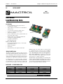
Description
TheMagtrolLoadMonitoringUnitisspeciallydesignedfor
straingaugetransducerapplications.Specificallydeveloped
for use with Magtrol load measuring pins and load-forceweightsensors,theLMUSeriesprovidesexcitationcurrent
andamplifiestheoutputsignaloffull-bridgestraingauges.
LoadMonitoringUnitsareflexibleandfullyconfigurable
due to DIP-switches and jumpers which allow the unit to
beeasilyinstalled—nosolderconnectionsarerequired.The
leveldetectorsandtheoutputscanbededicatedeithertothe
LMU 217
LMU 212
LMU 216
full-bridgeinput,tothevoltageinput,ortothesumofboth
(see “Application Selection” at the top of page 3).Abuilt-in
auto-diagnosticsystemdetectsanyshortcircuitsorsignalline
failures,thus allowing the system to be used in applications
where safety is important.Ifaproblemisdetected,both
relays are deactivated and the output voltage (respective
current)changesto>10VDCand>20mA.
TheLMUisfullycompatiblewithEuropeanCommunity(CE)
standards.ItsIP65aluminumhousingallowsthesystemto
beusedinharshenvironments.UsingSMD(surfacemounted
device)technology,theLMUallowsthemaximumperformance/
priceratioforstraingaugetransducermonitoring.
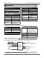
MoDel coMparison
Description
Voltage Output
Current Output
Relays
Summation
LMU 212
LMU 217
LMU 216
1 transducer input
1 × 0–10 V
1 × 0–20 mA or 4–20 mA
2
2 signals
2 transducer inputs (2 × LMU 212)
2 × 0–10 V
2 × 0–20 mA or 4–20 mA
4
3 signals
1 transducer input
3 × 0–10 V
1 × 0–20 mA or 4–20 mA
4
4 signals
www.magtrol.com
1
2
Chapter 1 – Introduction
Magtrol Load Monitoring Units LMU 212 & 217
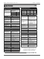
Specifications
INPUT CHARACTERISTICS
Power Supply
• 115–230 VAC and 20–32 VDC
Voltage
jumper selectable
• 48 VAC fixed
Fuse rating
Current
70 mA for 230 VAC
80 mAT
150 mA for 115 VAC 160 mAT
Maximum Current
250 mA for 20 VDC 400 mAT
350 mA for 48 VAC
400 mAT
Bridge signal
Supply Voltage
10 VDC
Max. Possible Current
140 mA DC
Sensitivity
0.5 to 4 mV/V
Max. Dynamic
Component of Bridge
±45 mVDC
Signal
Max. Common Mode
±10 V
Voltage on Input
Voltage Input for Summation of Another Load
Input Impedance
70 kΩ
Max. Input Signal
±10 V
(dynamic)
Signal Division by 2
DIP-switch selectable
Use Without Transducer Jumper selectable
Input for Auto-diagnostic Feature (OK I/P)
Type
Active if short circuited
OUTPUT CHARACTERISTICS
Relay Outputs
LMU 212: 2
Number of Relays
LMU 217: 4 (2 per input)
LMU 216: 4
Relay Behavior
Configurable with DIP-switch
4 A at 250 V AC
Max. Current per Contact
3 A at 30 V (0,5 A at 48 V DC)
Max. Voltage per
AC : 250 Veff
DC : 48 VDC
Contact
Contact Rating
90 W or 1000 VA
Contact-contact: 750 Veff
Insulation Voltage
Contact-coil: 1.5 kVeff
min. 105 (at 4 A, 250 V AC)
Lifetime
108 (unloaded)
Contact Resistance
< 20 mΩ
Current Output
Output Type
Current generator
Nominal Current Range 0 to 20 mA DC
Max. Current Range
0 to 25 mA DC
Max. Load
< 500 Ω for Imax = 20 mA
Output Impedance
> 50 kΩ
Voltage Output
Max. Dynamics
±10 V ≡ EM
Max. Load
≥10 kΩ (ε≤0.5%) [≥1 kΩ (ε≤5%)] *
Output Impedance
50 Ω (in series)
Output for Auto-diagnostic Feature (OK O/P)
Type
Open collector
LMU
TRANSFER CHARACTERISTICS
Voltage Transfer Ranges (∆UI/P / ∆UO/P)
Range
1
2
3
Bridge Sensitivity 0.42 to 0.78 0.7 to 1.3 1.2 to 2.2
[mV/V]
(0.6)
(1)
(1.7)
Voltage Transfer 2380 to 1280 1428 to 769 833 to 455
(gain)
(1670)
(1000)
(588)
Adjustment Range
±30%
±30%
±30%
Range Selection
Signal Division by 2
Measuring Chain Zero
Adjustment
Selectable using DIP-switches
DIP-switch selectable (the
available sensitivities then
moves from 0.84 to 4.4 mV/V
according to the selected
range)
Coarse adjustment using multiturn potentiometer: equivalent
to ±10 V/output for range 3
Fine adjustment using multiturn potentiometer: 5% of the
coarse adjustment
Temperature drift of the
≤ 200 ppm/°C
transfer function
Temperature drift of the
≤ 200 ppm of FSD/°C for
measuring chain zero
0.5 mV/V at the input ≡ ≤1
value
µV/°C
Current transfer range
Sensitivity Range with
± 20% of FSD on UO/P
Multi-turn Potentiometer
Nominal Current Range 0 to 20 mA DC
Max. Current Range
0 to 25 mA DC
Zero Adjustment Range ± 5 mA DC for IO/P ≥ 5 mA DC
Selectable low-pass filter
Filter Type
Butterworth
Filter Order
2
Selectable using DIP-switches
-3 dB Cut-off Frequency (0.3 Hz, 1 Hz, 3 Hz, 10 Hz,
100 Hz)
Level detectors
Number of Detectors
1 per relay
Level Adjustment Range
Hysteresis
Detection Indication
Switching Delay
-10 to +10 VDC using multi-turn
potentiometer (measured on
voltage output)
<0.5% or ≈ 5%
(DIP-switch selectable)
< or > (DIP-switch selectable)
0.01 to 4.25 seconds
Delay Adjustment Range (adjustment for every relay by
multi-turn potentiometer)
* NOTE: To guarantee precise calibration, the impedance of the
connected unit must be indicated at time of order. If this
value is unknown, an impedance of 1 MΩ will be used
for calibration. The resulting deviation will be ≤5%
with an impedance of ≥2 kΩ or ≤1% with ≥10 kΩ.
M AGTROL
2
3
Chapter 1 – Introduction
Magtrol Load Monitoring Units LMU 212 & 217
Specifications
LMU
TRANSFER CHARACTERISTICS (cont.)
Application selection
Output specific application:
REL1 det. REL2 det.
UO/P
I O/P
A, B or A+B A, B or A+B A, B or A+B A, B or A+B
A = bride signal; B = voltage input
MECHANICAL CHARACTERISTICS
Housing
Material
Aluminum
Stuffing glands
LMU 212:
3 × PG 11
Type and number
LMU 216 and 217: 6 × PG 11
Material
Nickel-plated brass
Terminal strip
MK8 (screw and connection at
Type
45°)
AWG 20 to 16
Max. Area of
Cross section: 0.5 to 1.5 mm²
Connecting Wire
(0.00077 to 0.0023 in²)
ENVIRONMENTAL CHARACTERISTICS
Operating Temperature
-40° C to +80° C
Storage Temperature
-45° C to +85° C
Protection Class
IP 65
Vibration and Shock
According to IEC 68.2
According to EN 61326-1
EMC
and EN 61326-2-3
SAFETY CHARACTERISTICS
B.I.T.E. test signal (Built In Test Equipment)
Load simulation on request
Signal type
(calibrated during the
installation)
Logic signal, active low, CMOS/
Control
TTL compatible
Reliability
MTBF
> 1,500,000 hours
aDDitional lMu 216 Functions
SUMMER
Number of Inputs
Input Voltage
Output Voltage
LATCHING
Control
Reset Signal
4 (UA, UB, UC and UD)
±10 V
UE1 = (UA + UB ± UC ± UD)X
X adjustable between 0.25 and
10
Using DIP-switches
RESET REL3, RESET REL4
CALIBRATION CIRCUIT
Volatile* digital memory at 12 bits
(memory reset at startup), the stored
digital value is substracted from the
input signal after D/A conversion
Principle
* Current interruptions lasting for less
than 30 ms do not lead to the loss of the
stored calibration value
Resolution
Storing Time
Output Impedence
Acceptable Load
Resistance
1/4096 of the selected range
<2s
< 200 Ω
≤ 20 kΩ
Basic conFiguration
TheLMULoadMonitoringUnitoffersunlimitedconfigurationpossibilities.Itisimpossibletolistthemallinthisdatasheet.
PleasecontactMagtroloroneofitssubsidiariesorsalesagentstodiscussyourspecificapplications.
Strain Gauge
Transducer
Voltage Input ±10 V
"OK" Input (OK I/P)
Power Supply
• 115–230 VAC (50/60 Hz)
• 20–32 VDC
• 48 VAC
Relay Output Contacts
• LMU 212/117: 2 per channel (RE1, RE2)
• LMU 216:
4 (RE1, RE2, RE3, RE4)
LMU
Load
Monitoring
Unit
"OK" Output (OK O/P)
Current Output 0–20 mA or 4–20 mA
Voltage Output(s) ±10 V
• LMU 212: 1
• LMU 216: 3
• LMU 217: 2
LMU 216 only:
Summer with 4 Voltage Inputs (±10 V)
M AGTROL
3
4
Chapter 1 – Introduction
Magtrol Load Monitoring Units LMU 212 & 217
Dimensions
LMU
lMu 212
Mounting screw
M6x30
A
B
L
K
Sealed diecast
aluminum box
A
B
C
D
E
G
J
K
L
M
N
E
C
D
J
G
Stuffing glands
Ø cable: 5 to 12 mm
M
N
OVERHEAD VIEW
mm
122
82
220
204
≈16
20.75
13.4
90
≈1.5
28
47
Model
Weight
LMU 212
2 kg
SIDE VIEW
J
M
K
lMu 216 anD lMu 217
N
N
P
P
P
N
SIDE VIEW
N
Mounting screw
M6x30
H
FRONT VIEW
C
D
Stuffing glands (max. PG 11)
Ø cables : 5 to 12 mm
E
F
Sealed diecast
aluminum box
A
B
C
D
E
F
H
J
K
M
N
P
mm
287
272
190
175
≈18
≈220
12
10
90
27
30
35
Model
Weight
LMU 216
4 kg
LMU 217 3.750 kg
B
A
OVERHEAD VIEW
M AGTROL
4
5
Chapter 1 – Introduction
Magtrol Load Monitoring Units LMU 212 & 217
Ordering Information
LMU
orDering inForMation
LOAD MONITORING UNIT
P/N 224 -
-000-
Model
• LMU 212 (1 input)
212
• LMU 216 (1 input)
216
• LMU 217 (2 inputs)
217
Supply
• 115–230 VAC (50/60 Hz) or 20–32 VDC
0
• 48 VAC (50/60 Hz)
4
Balancing comparator option (only for LMU 216)
LMU 216:
• No
11
• Yes
61
LMU 212:
• No (not available)
11
LMU 217:
• No (not available)
11
Configurated and calibrated?
• No (standard)
(blank)
• Yes (according to application and Magtrol Configuration and Calibration Protocol)
C
Due to the continual development of our products, we reserve the right to modify specifications without forewarning.
Magtrol inc
70 Gardenville Parkway
Buffalo, New York 14224 USA
Phone: +1 716 668 5555
Fax: +1 716 668 8705
E-mail: [email protected]
Magtrol sa
Centre technologique Montena
1728 Rossens / Fribourg, Switzerland
Phone: +41 (0)26 407 3000
Fax: +41 (0)26 407 3001
E-mail: [email protected]
6
Subsidiaries in:
Great Britain
Germany • France
China • India
Worldwide Network
of Sales Agents
LMU-US 04/10
www.magtrol.com
2. Installation / Configuration
2.1General information
It is essential to follow and apply the installation and configuration procedure described in this
chapter to avoid any perturbation of the measuring signal processed by an incorrectly installed LMU
212 or LMU 217.
Note :
The procedures described in this chapter do not cover all mounting
and connection possibilities. However, they can be used as a guide
for further customer specific applications. In case of doubt, the user
should not hesitate to contact Magtrol's customer service to find a
solution offering the best guaranty for optimal measuring accuracy.
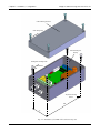
2.2Installation of the LMU 212 and LMU 217 load monitoring units
Note :
For optimal operation, the load monitoring unit should be run at
temperatures between -40° C and +80° C.
Both load monitoring units LMU 212 and LMU 217 being structurally very close to each other, their
mounting and the connection procedures are very similar :
1. Select a suitable mounting place free of vibrations. An instrument support, for instance,
offers excellent results.
2. Trace the location of the 4 screw taps on the mounting surface.
3. Drill and tap the 4 holes for the M6 mounting screws. The taps depth must be approximately
15 mm.
4. Remove the cover of the load monitoring housing. The LMU 212 cover is being fixed with
4 screws, the LMU 217 cover with 6 screws (see figures 2-1 and 2-2).
5. Position the housing on the mounting surface and fasten the 4 M6 x 30 mounting screws by
applying a fastening torque corresponding to the type of screw used.
6. Configure and calibrate the load monitoring unit if not already done according to the
procedure described in this chapter.
7. Carry out the necessary electrical connection and make sure that the housing stuffing glands
are water-tight.
8. Insert a copy of the calibration protocol (see Appendix A) into the load monitoring unit
housing before placing the cover back onto the housing and fastening its screws.
7
Chapter 2 – Installation / Configuration
Magtrol Load Monitoring Units LMU 212 & 217
Load monitoring unti cover
Cover fixing screw
Load monitoring unit
housing
Housing M6 x 30 fixing screw
M6 washer
Tap on the mounting
surface
204
82
Fig. 2–1 Installation of the LMU 212 load monitoring unit
8
Chapter 2 – Installation / Configuration
Magtrol Load Monitoring Units LMU 212 & 217
Load monitoring unit cover
Fixing screw for cover
M6 x 30 housing
fixing screws
M6 washer
Load monitoring unit housing
Taps on the
assembly surface
272
175
Fig. 2–2 Installation of the LMU 217 load monitoring unit
9
Chapter 2 – Installation / Configuration
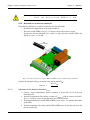
2.3
Magtrol Load Monitoring Units LMU 212 & 217
Connection of the LMU 212 and LMU 217 load monitoring units
The LMU 212 and LMU 217 load monitoring units are fitted with stuffing glands maintaining the
connection cables and securing the tightness of the unit's housing. To pass the cables through the
stuffing glands simply apply the following procedure :
1. Uninsulate the conductors of the different cables.
2. Remove the housing cover after having unscrewed the fixing screws.
3. Pass the cables through the stuffing glands as shown on figure 2–3 :
a. Unscrew the hex nut by rotating it counterclockwise. The main body of the stuffing
gland should not be removed from the unit's housing.
b. Extract the internal and external gasket from the hex nut . Both gaskets are used
to compensate for the different cable diameters. Push the internal gasket to extract it
from the external gasket .
c. Pass the cable through the hex nut , the internal gasket (when used), the external
gasket , the sealing ring and the main body .
d. Reassemble the stuffing gland and coat the front part of the external gasket with
silicone (see figure 2–3) before screwing the hex nut onto the main body . Tighten
the hex nut in such a way that the internal gasket and/or the external gasket
protrudes, so as to provide the degree of watertightness required.
e. Ensure also that the cable is held firmly in the stuffing gland.
Caution :Do not damage the gaskets with cutting objects. Check that no
foreign bodies have slid between the elements of the stuffing
gland.
Degrease the surface of the cable which will come into
The seal of the stuffing gland cannot
be guarantied if these instructions are not followed.
contact with the gasket.
Assembled stuffing gland
Protruding gasket
Cable
Internal gasket
Hex nut
Sealing ring
External gasket
Only grease
the front part
Main body
Fig. 2–3 Stuffing gland (overall and exploded view)
4. Connect the conductors of the various cables to the load monitoring unit terminals.
5. Put the cover back on the load monitoring unit and tighten up its six screws.
10
Chapter 2 – Installation / Configuration
Magtrol Load Monitoring Units LMU 212 & 217
2.4
Configuration of the Load monitoring Unit
Note :
The asterisks (¶) correspond to the standard configuration of the
LMU 212 version 0XX and LMU 217 version 0XX, that is to say
the basic uncalibrated modules.
The configuration of the LMU 212 and LMU 217 load monitoring units include all start-up operations
which are necessary to achieve a trouble free operation. This ranges from the supply voltage to
the selection of the application, the sensor connection, the energising mode of the relays and their
delay time, the selection of the pass-band and the sensor sensitivity. As a reminder: the LMU 217
is composed of two LMU 212.
2.4.1
Adaptation of the monitor to the available supply unit
2.4.1.1
Supply voltage
Before connecting the LMU 212 or LMU 217 load monitoring unit, select its operating voltage by
correctly positioning the jumper (DC or AC voltage) and then, in case of an AC supply, choosing
the correct voltage by means of the switch. Finally choose the supply fuse rating.
Warning! The monitoring unit can be seriously
damaged if not destroyed, if this advice is not
followed.
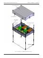
The information given in figures 2–4 to 2–6 and in the table on the next page allows the user to
select the operating voltage of the load monitoring unit, to choose the supply fuse and to assign the
supply terminals.
Terminal
11.
.. .
..
.. ..
. .. .
. ..
23
24
.. .
. ..
.. . .
..
. ..
21
22
.. .
. ..
. .. .
. ..
.. .
. ..
... .
..
Operating voltage selection
jumper and switch
. 220
0
Supply fuse
Fig. 2–4 Load monitoring unit board with location of the selection elements
11
Chapter 2 – Installation / Configuration
Magtrol Load Monitoring Units LMU 212 & 217
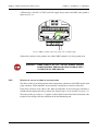
1. Place the jumper according to the selected supply mode (see figure 2–5) :
- 'DC' for a DC type supply with a voltage between 20 and 32 VDC
- 'AC' for an AC type supply (230 VAC, 115 VAC or 48 VAC)
2. In case of an AC supply position the switch on (see figure 2–5) :
- '230 V' for an AC voltage of 230 VAC
- '115 V' for an AC voltage of 115 VAC
- for operating voltages of 48 VAC or 20 to 32 VDC the position of the switch is irrelevant.
Operating voltage
115 VAC
Operating voltage
230 VAC
Operating voltage
48 VAC
Operating voltage
20 to 32 VDC
Fig. 2–5 Jumper and switch configuration
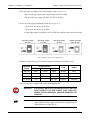
3. Check the rating of the fuse inserted in its support according to the following table:
Supply terminals
Operating
voltage
0 V (18)
N (19)
P (20)
230 VAC
earth
neutral
115 VAC
earth
48 VAC
20 - 32 VDC
Fuse
Switch
phase
80 mAT
230 V
neutral
phase
160 mAT
115 V
earth
neutral
phase
400 mAT
irrelevant
0V
—
20 - 32 V
400 mAT
irrelevant
A fuse of each rating is supplied with each load monitoring unit.
Warning!For safety reasons it is important to secure
the stability of the supply unit used and
respect the operating voltage selected on
the lmu.
Note :
Do not forget to report the designation of the collected external
signals connected to the supply terminal on the configuration and
calibration form (see Appendix A).
12
Chapter 2 – Installation / Configuration
Magtrol Load Monitoring Units LMU 212 & 217
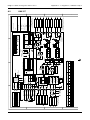
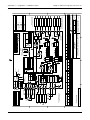
C
B
A
THE INFORMATION DISCLOSED HEREIN WAS ORIGINATED BY AND IS THE PROPERTY OF MAGTROL SA.
MAGTROL SA RESERVES ALL PATENT PROPRIETARY, DESIGN, USE, SALE, MANUFACTURING AND
REPRODUCTION RIGHTS THERETO.
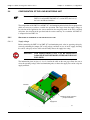
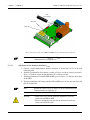
4. When using a 230 VAC, 115 VAC or 48 VAC supply always connect the LMU to the ground as
shown on figure 2–6 :
1
2
Fig. 2–6 LMU grounding when using a 230, 115 or 48 VAC supply
6
5
4
3
2
1
Connect the earth wire to the ground screw and the LMU terminal n° 18 to the ground screw.
3
12.12.02
C.S.
N.B.
03.12.01
01062
C.S.
N.B.
02.07.97
97133
C.B.
N.B.
Rev.
Date
Tolerances: ±
02076
PM
Drawn
Appr.
mm to 50mm, ±
Pos.17 removed !
Pos.5 and 6 changed; pos. 9 removed !
Pos. 18 added
Repl. by :
Repl. for:
mm over 50mm
Material:
Finish:
MONITORING UNIT
Warning! When using a 48 / 115 / 230 VAC supply LOAD
always
LMU 112
make
sure that the LMU
housing is adequately
A
B
C
connected to the ground!
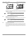
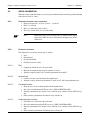
2.4.2Selection of the type of wiring to the strain gauge
The choice of the type of wiring depends on the length of the cable between the LMU and the strain
gauge transducer, on the impedance of the transducer and the linear resistance of the cable.
If the linear resistance of the cable is ≤0,1 W/m, the impedance of the strain gauge transducer is
≥200 W and the length of the cable is ≤100 m, the wiring of type 1 can be selected (see figure 2–7).
The wiring of the type 2 of figure 2–7 applies to cable lengths of more then 100 m or when the cable
length has been changed after the calibration of the load monitoring unit.
13
Scale
1:5
Dr
Che
App
DRAWING N°
LMU21
Chapter 2 – Installation / Configuration
Magtrol Load Monitoring Units LMU 212 & 217
Strain gauge
transducer
16
Supply +
Strain gauge
transducer
21
Supply +
SENSE +
16
13
Signal +
13
Signal +
12
Signal -
12
Signal -
17
Supply -
22
Wiring type 1
17
SENSE Supply -
Wiring type 2
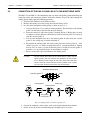
Fig. 2–7 Wiring types
For applications in conformity with the TÜV standard detecting short-circuits and/or failure of a
conductor in the connecting cable is compulsory. In this case no signal must be sent on terminals
21 (SENSE+) and 22 (SENSE-).
Note :
Record the length of the cable between the transducer and the LMU
as well as its type on the configuration and calibration form (see
Appendix A).
2.4.3Designation of the voltage and current inputs/outputs
The LMU load monitoring unit is fitted with a voltage input (UI/P ) and also with two outputs, one
for voltage (UO/P ) and one for current (IO/P ).
Note :
Record the designation of the external signals linked with UI/P , UO/P
and IO/P on the configuration and calibration form (see Appendix
A).
2.4.4Configuration of the detection chains
The load monitoring unit relays are used to detect under- and overloads. In case of an overload,
the relay is de-energised when the output voltage UO/P is lower than the threshold voltage Ulevel.
In case of an underload the output voltage must be higher than the threshold voltage to de-energise
the relay. We shall come back on the adjustment of the threshold voltage when calibrating the load
monitoring unit.
14
Chapter 2 – Installation / Configuration
Magtrol Load Monitoring Units LMU 212 & 217
Detection chain for relay 1 (REL1)
Micro-interrupteurs
SWA
7
8
9
10
1
2
3
4
5
6
ON
Figure 2–11 indicates the location of the SWA micro-switches on the load monitoring unit board.
OF
F
2.4.4.1
Fig. 2–8 Location of the SWA micro-switches
The following table allows the user to select the energising mode and the hysteresis value for the
relay REL1.
Configuration
Condition
SWA4 SWA5 SWA6
Effect
REL1 de-energised for
F < Flevel1
ON
OFF
—
Detection for UO/P < Ulevel1
REL1 de-energised for
F > Flevel1
OFF
ON
—
Detection for UO/P > Ulevel1
Hysteresis < 0.5%
—
—
OFF
Hysteresis < 50 mV measured on UO/P
Hysteresis ≈ 5% (FSD)
—
—
ON
Hysteresis ≈ 500 mV measured on UO/P
Note :
Record the value Flevel1 and the configuration of the micro-switches
SWA4, SWA5 and SWA6 on the configuration and calibration form
(see Appendix A).
This table allows the user to select the configuration of the micro-switches according to the state
of the relay REL1.
15
Chapter 2 – Installation / Configuration
Magtrol Load Monitoring Units LMU 212 & 217
State of relay REL1
Contact
REL1A - REL1C
Contact
REL1A - REL1B
REL1 energised
Closed
Open
REL1 de-energised
Open
Closed
The relay REL1 also operates as a line check relay and is de-energised in case of short-circuit or
line failure.
Note :
2.4.4.2
Record the designation of the external signals linked to REL1A,
REL1B and REL1C on the configuration and calibration form (see
Appendix A).
Detection chain for relay 2 (REL2)
Figure 2–8 on the previous page indicates the location of the SWA micro-switches on the load
monitoring unit board. The following table allows the user to select the energising mode and the
hysteresis value for the relay REL2.
Configuration
Condition
SWA7 SWA8 SWA9
Effect
REL2 de-energised for
F < Flevel2
ON
OFF
—
Detection for UO/P < Ulevel2
REL2 de-energised for
F > Flevel2
OFF
ON
—
Detection for UO/P > Ulevel2
Hysteresis < 0.5%
—
—
OFF
Hysteresis < 50 mV measured on UO/P
Hysteresis ≈ 5% (FSD)
—
—
ON
Hysteresis ≈ 500 mV measured on UO/P
Note :
Record the value Flevel2 and the configuration of the micro-switches
SWA7, SWA8 and SWA9 on the configuration and calibration form
(see Appendix A).
This table allows the user to select the configuration of the micro-switches according to the state
of the relay REL2.
State of relay REL2
Contact
Contact
REL2A – REL2C REL2A – REL2B
REL2 energised
Closed
Open
REL2 de-energised
Open
Closed
The relay REL2 also operates as a line check relay and is de-energised in case of short-circuit or
line failure.
Note :
Record the designation of the external signals linked to REL2A,
REL2B and REL2C on the configuration and calibration form (see
Appendix A).
16
Chapter 2 – Installation / Configuration
Magtrol Load Monitoring Units LMU 212 & 217
2.4.4.3
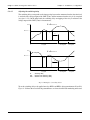
Adjusting the switching delay
The switching delay corresponds to the time passing between the moment when the detection level
is reached at the voltage output of the LMU (UO/P) and the moment when the relay is de-energized
(see figure 2–12). On the other hand, the switching delay on tripping of the relay in relation to the
voltage output of the LMU (UO/P) is instantaneous.
F > Fthreshold 1 or 2
UO/P
Uthreshold 1 or 2
D
ON
OFF
ON
t
OFF
REL 1 or 2
energised
REL 1 or 2
energised
REL 1 or 2
de-energised
F < Fthreshold 1 or 2
UO/P
Uthreshold 1 or 2
D
ON
OFF
ON
REL 1 or 2
energised
D:
ON :
OFF :
t
OFF
REL 1 or 2
de-energised
REL 1 or 2
energised
switching delay
tripping of the switching delay
release of the switching delay
Fig. 2–9 Examples of switching delays
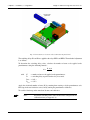
To set the switching delay to be applied on relays REL1 and REL2, adjust potentiometer P1 and P2.
Figure 2–10 shows the user where the potentiometers are located on the load monitoring unit board.
17
Chapter 2 – Installation / Configuration
Magtrol Load Monitoring Units LMU 212 & 217
P1
P2
P3
P4
P5
P6
Potentiomètres
d'ajustement
P7
P8
P9
P10
Fig. 2–10 Potentiometer location on the load monitoring unit board
The switching delays D1 and D2 are applied to the relays REL1 and REL2. The method of adjustment
is as follows :
To determine the switching delay value, calculate the number of turns to be applied to the
potentiometers using the following formula :
N = D - 0,01
0,170
withN
= number of turns to be applied to the potentiometer.
= switching delay required for the relay in seconds.
D
Dmin = 0,01 s
Dmax = 4,25 s
Apply the calculated number of turns (N) by counting them starting at 0 (the potentiometer at its
limit stop in the anti-clockwise sense) and by turning the potentiometer clockwise.
To reach the limit stop, make more than 30 turns anti-clockwise.
Note :
Record the switching values of D1 and D2 on the configuration and
calibration form (see Appendix A).
18
Chapter 2 – Installation / Configuration
Magtrol Load Monitoring Units LMU 212 & 217
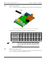
2.4.5Selection of the pass band
Figure 2–11 indicates the location of the SWB micro-switches on the load monitoring unit board.
7
8
9
10
1
2
3
4
5
6
OF
F
ON
SWB
micro-switches
Fig. 2–11 Location of the SWB micro-switches on the load monitoring unit board
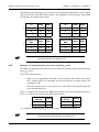
The following table allows the user to select the pass band of the output signal.
fC frequency range
SWB1 SWB2 SWB3 SWB4 SWB5 SWB6 SWB7 SWB8
DC to 100 Hz
OFF
OFF
OFF
OFF
OFF
OFF
ON
ON
DC to 10 Hz
OFF
OFF
OFF
OFF
ON
ON
OFF
OFF
DC to 3 Hz
OFF
OFF
ON
ON
OFF
OFF
OFF
OFF
DC to 1 Hz
ON
ON
OFF
OFF
OFF
OFF
OFF
OFF
DC to 0,3 Hz
OFF
OFF
OFF
OFF
OFF
OFF
OFF
OFF
Note :
Record the value of the cut-off frequency fc and the configuration of
the micro-switches SWB1, SWB2, SWB3, SWB4, SWB5, SWB6,
SWB7 and SWB8 on the configuration and calibration form (see
Appendix A).
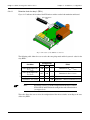
2.4.6Selection of the sensitivity range
Figure 2–18 indicates the location of the SWA micro-switches on the load monitoring unit board.
Figure 2–11 indicates the location of the SWB micro-switches.
19
Chapter 2 – Installation / Configuration
Magtrol Load Monitoring Units LMU 212 & 217
The following table allows the user to select the sensitivity range of the strain gauge transducer.
Strain gauge sensitivity
[mV/V]
SWA1
SWA2
SWB10
0,42 to 0,78
OFF
OFF
ON
0,7 to 1,3
ON
OFF
ON
1,2 to 2.2
ON
ON
ON
With a strain gauge transducer connected to the load monitoring unit featuring a higher sensitivity
than listed on the above table it is possible to use the function dividing the signal by two (and therefore
use transducers with up to 4.4 mV/V sensitivity). See chapter 2.4.8, "Division of the transducer
signal or the input voltage UI/P by two".
Note :
Record the selected strain gauge sensitivity as well as the
configuration of the micro-switches SWA1, SWA2 and SWB10 on
the configuration and calibration form (see Appendix A).
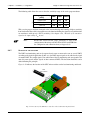
2.4.7Selection of the application
The LMU load monitoring unit can be operated on its own or connected to one or several LMUs
according to the desired application. In this case, the LMU output signal can be added to the signal
of another LMU. The output signals UO/P and/or IO/P of the last monitoring unit correspond to the
sum of its own signals and the signals of other connected LMUs. The detection thresholds can be
added following the principle.
SWC
micro-switches
7
8
9
10
1
2
3
4
5
6
OF
F
ON
Figure 2–12 indicates the location of the SWC micro-switches on the load monitoring unit board.
Fig. 2–12 Location of the SWC micro-switches on the load monitoring unit board
20
Chapter 2 – Installation / Configuration
Magtrol Load Monitoring Units LMU 212 & 217
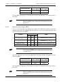
The following table allows the user to select the desired application independently for each output
and relay by means of the SWC micro-switches. A corresponds to the strain gauge signal and B
corresponds to the monitor input voltage.
IO/P
SWC1
SWC5
A
ON
OFF
B
OFF
A+B
ON
Detection level
SWC3
REL1
UO/P
SWC2
SWC6
A
ON
OFF
ON
B
OFF
ON
ON
A+B
ON
ON
ON
OFF
B
OFF
A+B
ON
Note :
Detection level
SWC4
REL2
SWC7
A
SWC8
A
ON
OFF
ON
B
OFF
ON
ON
A+B
ON
ON
Record the SWC micro-switch configuration on the configuration
and calibration form (see Appendix A).
2.4.8Division of the transducer signal or the input voltage Ui/p by two
The LMU load monitoring unit allows the user to divide the transducer signal or/and the voltage
input UI/P, by two.
This can for instance happen:
- in the case of an application A + B (with A as the transducer signal and B as the voltage
UI/P), with the signal at its maximum, the sum will generate an output voltage U O/P
exceeding 10 VDC
- when the transducer signal is too big (between 2 and 4 mV/V), the load monitoring unit
gain can be divided by two.
Figure 2–8 indicates the location of the SWB micro-switches on the load monitoring unit board.
Figure 2–11 indicates the location of the SWC micro-switches.
Transducer
signal (A)
SWB10
Voltage input
UI/P (B)
SWC10
Divided by 2 (:2)
OFF
Divided by (:2)
ON
Full (:1)
ON
Full (:1)
OFF
As a reminder: the input signal UI/P must remain within -10 VDC and +10 VDC.
Note :
Record the SWB and SWC micro-switch configuration on the
configuration and calibration form (see Appendix A).
21
Chapter 2 – Installation / Configuration
Magtrol Load Monitoring Units LMU 212 & 217
2.4.9Use without transducer
The LMU load monitoring unit can be operated without transducer, just by using its voltage input
UI/P. This can be useful when the user wants to take advantage of the voltage-current converter or
relays functions.
1. Activate the transducer presence simulation (to avoid any internal fault detection in
relation with the transducer) according to figure 2–13 and the following table:
. .
23
. .
24
. .
21
. .
22
. .
. .
. .
. .
. .
. .
. 2
0
JP
J 5
JP P6
JP 7
8
1
Fig. 2–13 Location of the transducer presence simulation jumpers
Transducer presence simulation
jumper:
Jumper on:
Activated
JP5, JP6
Deactivated
JP7, JP8
2. If necessary, adjust zero on the voltage UO/P or current IO/P. output (see chapter 3.1.1
"Zero adjustment on the voltage output", respectively chapter 3.1.2 "Zero adjustment on
the current output".
3. Configure the relays detection thresholds according to chapter 3.5 "Adjustment of the
Ulevel1 and Ulevel2 detection thresholds".
Note :
Record the position of the jumpers JP5 to JP8 on the configuration
and calibration form (see Appendix A).
22
3. Calibration
Two types of calibration are available on the LMU 212 and LMU 217:
• Standard electrical calibration (see paragraph 3.1)
• Quick calibration with reference loads (see paragraph 3.2).
Paragraph 3.3 handles the calibration of the built-in test equipment B.I.T.E.
3.1Electrical calibration (standard)
Zero adjustment on the voltage output
The following conditions are required for the zero adjustment on the voltage output:
• No load must be applied on the transducer.
• The micro-switch SWB9 (see figure 3–3) must be OFF.
• The micro-switch SWC2 (see figure 3–2) must be ON.
Proceed as follows to carry out the zero adjustment:
1. Connect a digital millivoltmeter between terminals 15 (UO/P) and 9 (0 V) of the load
monitoring unit.
2. Adjust the potentiometers P6 and P7 to get a reading of 0 V ±10 mV on the millivoltmeter.
Figure 3–1 indicates the location of the potentiometers P1 to P10.
ON
SWB
micro-switches
7
8
9
10
1
2
3
4
5
6
F
OF
3.1.1
REL1 LED
REL2 LED
L1
RE
L2
RE
Fig. 3–1 Location of the potentiometers on the load monitoring unit board
23
Chapter 3 – Calibration
3.1.2
Magtrol Load Monitoring Units LMU 212 & 217
Zero adjustment on the current output
The following condition is required to adjust the zero on the current output :
• The micro-switch SWA10 (see figure 3–2) must be OFF.
In this configuration the current output does not depend on the applied load. This allows the user
to carry out an accurate adjustment on the current output.
Proceed as follows to carry out the zero adjustment:
1. Connect a digital milliampermeter between terminals 10 (IO/P) and 9 (0 V) of the load
monitoring unit.
2. Adjust the potentiometer P8 to get the initial value with an accuracy of ±50 μA, for instance
4 mA ±50 μA, on the milliampermeter. Figure 3–1 indicates where the potentiometer P8 is
located.
3.1.3Sensitivity adjustment on the voltage output
To adjust the sensitivity on the voltage output (UO/P, terminal 15), carry out the following operations:
1. Apply a known load Fknown > ½ · Fnominal on the transducer:
Fnominal ≡ UO/P nominal = 10 V DC
UO/P known ≡ Fknown
2. To determine the rating of the voltage output, carry out the following calculation:
10 V × Fknown
UO/P known =
Fnominal
3. Connect a numerical milliampermeter between terminals 15 (UO/P) and 9 (0 V) of the load
monitoring unit.
4. Adjust the potentiometer P4 to get a reading of UO/P known with an accuracy of ±10 mV.
Figure 3–1 indicates where the potentiometer P4 is located.
3.1.4Sensitivity adjustment on the current output
To adjust the sensitivity on the current output (IO/P, terminal 10) maintain the load Fknown on the
transducer. First carry out the procedures described in the paragraphs 3.1.1 to 3.1.3 and then proceed
as follows:
1. To determine the rating of the current output make the following calculation:
IO/P known =
16 mA × Fknown
Fnominal
+ 4 mA
2. Connect a numerical milliampermeter between terminals 10 (IO/P) and 9 (0 V) of the load
monitoring unit.
3. Position the micro-switches SWC1 and SWA10 and ON so as the current output depends
on the applied load.
4. Adjust the potentiometer P10 to get a reading of IO/P know with an accuracy of de ±50 μA.
Figure 3–1 indicates where the potentiometer P10 is located.
24
Chapter 3 – Calibration
Magtrol Load Monitoring Units LMU 212 & 217
Warning :T h e
l oa d m o n i t o r i n g u n i t w i l l o n ly b e o p e r at i o na l
when
the
micro
-switch
SWA 1 0
is
ON .
3.1.5 Adjustment of the detection thresholds
SWC
micro-switches
7
8
9
10
1
2
3
4
5
6
OF
F
ON
The following conditions are required to adjust the detection thresholds:
• No load must be applied to the strain gauge transducer.
• The micro-switch SWB9 (see figure 3–3) must be ON to activate the test signal.
• To adjust the detection thresholds Ulevel1 and Ulevel2 place the micro-switches SWC3 and
SWC4 (see figure 3–2) on ON.
Fig. 3–2 Location of the micro-switches SWC3 and SWC4 on the load monitoring unit board
Calculate the threshold voltages in relation to the voltage output UO/P :
UO/P level =
3.1.5.1
10 V × Flevel
Fnominal
Adjustment of the detection threshold Ulevel1
1. Connect a digital millivoltmeter between terminals 15 (UO/P) and 9 (0 V) of the load
monitoring unit.
2. Adjust the potentiometer P9 to obtain a reading of UO/P level1 with an accuracy of ±20 mV.
Figure 3–1 indicates where the potentiometers P1 to P10 are located.
3. Turn the potentiometer P3 until the LED on REL1 goes on. Figure 3–3 indicates the location
of this LED.
4. Turn the potentiometer P3 slowly until the LED of REL1 goes off: the detection level will
then be switched off.
25
Chapter 3 – Calibration
Magtrol Load Monitoring Units LMU 212 & 217
7
8
9
10
1
2
3
4
5
6
OF
F
ON
SWB
micro-switches
REL1 LED
REL2 LED
L1
RE
L2
RE
Fig. 3–3 Location of the relays REL1 and REL2 on the load monitoring unit board
3.1.5.2
Note :
Record the values UO/P level1 and Flevel1 on the configuration and
calibration form (see Appendix A).
Adjustment of the detection threshold Ulevel2
1. Connect a digital millivoltmeter between terminals 15 (UO/P) and 9 (0 V) of the load
monitoring unit.
2. Adjust the potentiometer P9 to obtain a reading of UO/P level2 with an accuracy of ±20 mV.
Figure 3–1 indicates where the potentiometers P1 to P10 are located.
3. Turn the potentiometer P5 until the LED on REL2 goes on. Figure 3–3 indicates the location
of this LED.
4. Turn the potentiometer P5 slowly until the LED of REL2 goes off: the detection level will
then be switched off.
Note :
Warning :
Record the values UO/P level2 and Flevel2 on the configuration and
calibration form (see Appendix A).
• After having adjusted the detection thresholds place the micro-switch SWB9 on OFF.
• The load monitoring unit will only be operational when the micro-switch SWA10 is ON.
26
Chapter 3 – Calibration
Magtrol Load Monitoring Units LMU 212 & 217
3.2
Quick Calibration
When the electric calibration is not easy to carry out (environment, time constraints) quick calibration
with reference loads is a must.
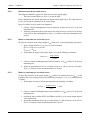
3.2.1Operations preceding a quick calibration
1. Requested signal of 0 - 10 V for „0 load“ – „overload“
2. Relay 1 = overload
3. Relay 2 = underload (slack of cable)
4. The relays switch off in case of overshooting.
Note :
When other devices such as display units are connected, the output
signal of the LMU 212 must correspond to the input signal of the
said devices.
3.2.2Calibration procedure
The calibration is carried out in four steps as follows:
1.Zero
2.Nominal load
3. Overload threshold
4. Underload (slack of cable).
3.2.2.1Zero
1. Completely unload the axis / the crane hook.
2. Measure the output voltage between terminals 15 and 9.
3. Adjust the output voltage to 0 V with the potentiometers P6 and P7.
3.2.2.2
Nominal load
1. Load the axis /the crane hook with the nominal load.
2. Adjust the voltage between the terminals 15 and 9 to 10 V with the potentiometers P4.
3.2.2.3
Overload threshold
1. Keep the axis / the crane hook loaded with the nominal load.
2. Select the overload function F>FL for relay 1 (SWA4=OFF/SWA5=ON).
3. Turn the potentiometer P3 (for the level 1) until the relay switches off (the LED will go
off).
4. Finely turn the potentiometer P3 until the relay switches on.
3.2.2.4
Underload (slack of cable)
1. Unload the axis / the hook or the cable hoist.
2. Select the underload function F<FL for relay 2 (SWA7=ON/SWA8=OFF).
3. Turn the potentiometer P5 (for the level 2) until the relay switches off (the LED will go
off).
4. Finely turn the potentiometer P5 until the relay switches on.
27
Chapter 3 – Calibration
3.3
Magtrol Load Monitoring Units LMU 212 & 217
Calibration of the built-in test equipment (B.I.T.E.)
The built-in test equipment (B.I.T.E.) is based on a signal simulating a fictitious load passing through
the complete signal amplification chain. At each call of the B.I.T.E. function the user will be able
to check on the various outputs (voltage UO/P and current IO/P) as well as on the relays REL1 and
REL2 that the load monitoring unit reacts to this fictitious load as if it would be a real load.
The calibration requires the following conditions:
• The load monitoring unit calibration according paragraph 3.1 or paragraph 3.2 must already
have been carried out.
• No load must be applied to the transducer.
• The micro-switch SWB9 (see figure 3–3) must be on position ON.
The calibration is carried out as follows:
1. Connect a digital millivoltmeter between terminals 15 (UO/P) and 9 (0 V) of the load
monitoring unit (for the voltage calibration) or the milliampermeter between terminals 10
(IO/P) and 9 (0V) (for the current calibration).
2. Adjust the potentiometer P9 to obtain a reading of UO/P with an accuracy of ±20 mV for the
voltage calibration or a reading of IO/P with an accuracy of ±50 μA for the current calibration.
Warning :Adjust the B.I.T.E. to get UO/P between -10 VDC and +10 VDC.
If this output is not within these limits turn the potentiometer
P9 back to its half-way position and carry out a fine adjustment.
Figure 3–1 shows where the potentiometers P1 to P10 are located.
3. Put the micro-switch SWB9 back on OFF.
28
4. Applications
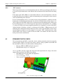
4.1Using one or several load monitoring units
A load monitoring unit can be used as a stand-alone or combined with other load monitoring units.
In the second case the different measuring signals are cascaded and their sum appears on the output
of the load monitoring unit at the end of the chain. It is however possible to pick up the measuring
signal at the level of each element of this chain.
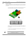
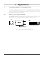
4.1.1Using one single load monitoring unit LMU 212
In this application the single load monitoring unit runs with only one transducer. The micro-switches
SWC1 to SWC8 of the load monitoring unit must be configured as shown on figure 4–1.
Capteur
Micro-interrupteurs SWC
Fig. 4–1 Using one single load monitoring unit LMU 212
29
Chapter 4 – Applications
Magtrol Load Monitoring Units LMU 212 & 217
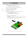
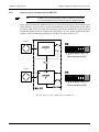
4.1.2Using one single load monitoring unit LMU 217
Note :
A LMU 217 type load monitoring unit is composed of two LMU
212 load monitoring units placed side by side in a common housing.
In this application both load monitoring units are used and connected together. The measuring signal
of the transducer A is processed by the first load monitoring unit. Its voltage output is then sent to
the voltage input of the second unit. The measuring signal of the transducer B is processed by the
second load monitoring unit and added to the input voltage. To carry out this operation the microswitches of the load monitoring units must be configured as shown on figure 4–2.
Capteur A
Micro-interrupteurs SWC
Capteur B
Micro-interrupteurs SWC
Fig. 4–2 Using one single load monitoring unit LMU 217
30
Chapter 4 – Applications
Magtrol Load Monitoring Units LMU 212 & 217
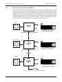
4.1.3Using three load monitoring units LMU 212
In this application three load monitoring units are used and connected together. The signal of the
transducer A is processed by the first load monitoring unit, the signal of the transducer B by the second
and the signal of the transducer C by the third. The voltage output of the first unit is connected to the
voltage input of the second unit and added to the processed measuring signal of the transducer B.
The voltage output of the second unit is connected to the voltage input of the third unit and finally
added to the processed measuring signal of the transduce C. To carry out this operation the microswitches of the load monitoring units must be configured as shown on figure 4–3.
Capteur A
Micro-interrupteurs SWC
Capteur B
Micro-interrupteurs SWC
Capteur C
Micro-interrupteurs SWC
Fig. 4–3 Using three load monitoring units LMU 212
31
Chapter 4 – Applications
Magtrol Load Monitoring Units LMU 212 & 217
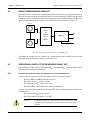
4.2Using transducers in parallel
By using up to four transducers per load monitoring unit in parallel an average signal can be obtained.
They can be connected to the connexion box JB 113 for two transducers or JB 114 for up to four
transducers. The box is then connected to the transducer input of the load monitoring unit. The latter
operates as if it would just have to process the signal of only one transducer(see figure 4–4).
Capteur A
Boîte
de
jonction
JB 113
ou
JB 114
IO/P
LMU 212
UO/P
OKO/P
Capteur D
Fig. 4–4 Using one single load monitoring unit LMU 212
The number of transducers to be connected to a load monitoring unit is limited to four and the
impedance of the resulting chain must be greater than 75 Ω.
4.3Operational check of the measuring chain ("OK")
Each load monitor is fitted with an "OK" input (OKI/P) and output (OKO/P) for the operational check
of the signal processing and transmission.
4.3.1Checking the transducer signal transmission to the load monitoring unit
A short circuit or a signal transmission line failure will have the following effects :
• The relays REL1 and REL2 will be de-energised.
• The output current IO/P will be > 20 mA.
• The output voltage UO/P will be > 10 V DC.
• The output OKO/P will switch to error mode (low impedance).
A failure of the line connected to the voltage input UI/P of the load monitoring unit will have the
following effects :
• The current output IO/P will be > 20 mA.
• The voltage output UO/P will be > 10 V DC.
Caution : If
UI/P signal division by two is activated (i.e. when
SWC10 is ON), no line failure will be detected on
the voltage input
the micro-switch
this input.
32
Chapter 4 – Applications
Magtrol Load Monitoring Units LMU 212 & 217
4.3.2
“OK” philosophy
When using simultaneously several load monitoring units, the "OK" inputs and outputs allow the user
to cascade the operational checks of the different units and obtain overall control of the measuring
chain.
If the output signal "OK" (OKO/P) of a load monitor indicates a fault (low impedance), either the
transmission between the transducer and the load monitoring unit is interrupted or short-circuited,
or the load monitoring unit is defective.
If several load monitoring units are cascaded, the unit causing potentionally a problem sends this
information to all following monitoring units. So, all effects described in the previous chapter 4.3.1
will be displayed on the LMU outputs and on all downstream load monitoring units connected to
the measuring chain. In case of a defect inspect the output voltages UO/P [terminal (15)– grounding
(7), voltage >10 VDC] or the current output IO/P [terminal (10)– grounding (7), current >20 mADC].
Another method of localising a default is to interrupt the line OKI/P − OKO/P between the load
monitoring units and then short-circuit terminal (8) and (11) of the suspected LMU(s). If the voltage
measured between terminal (8) and the ground (7) is less than 1 VDC, something must be wrong
with the LMU. If the voltage is around 24 VDC, the LMU is ok. Remove the short circuit after
having carried out the measurements.
4.5Permanent supply check
The load monitoring unit LMU is fitted with a device, which permanently checks the internally
generated voltage supplies. Any drop of one of these voltages causing a problem on the LMU will
force the LMU to switch to error mode with the following effects:
• The relays REL1 and REL2 will be de-energised.
• The LED shown on figure 4–5 will go off.
As far as possible (the basic supply units must still remain operational) the voltage and current
outputs (UO/P respectively II/P) indicate the problem:
• The OKO/P will go on error mode (low impedance).
• Current output IO/P > 20 mA.
• Voltage output UO/P > 10 V DC.
"OK supply" LED
Fig. 4–5 Permanent supply check LED
33
Chapter 4 – Applications
Magtrol Load Monitoring Units LMU 212 & 217
If an error is detected, the user will have to check:
- the wiring in general (short-circuits or disconnected cables) and specially the transducer
connections and impedance (must be less than 75 Ω),
- if the LMU supply configuration is correct (see chapter 2.4.1)
- the state and the rating of the LMU fuse.
If after having checked these points the problem is still present the LMU may be defective.
4.6Using B.I.T.E. signal
The load monitoring unit LMU is fitted with system testing the amplification chain of the signal
generated by the transducer. The B.I.T.E. test signal simulating a load must be calibrated when
installing the LMU (see chapter 3.3).
To activate the function two possibilities are available :
• connect the B.I.T.E. control input (terminal 23) to the ground (terminal 24), see figure 4–6.
• send a "low active" CMOS/TTL compatible control signal (see following table) on the
B.I.T.E. (signal on terminal 23, ground on terminal 24):
B.I.T.E.
function
Necessary
logic state
B.I.T.E. input terminals condition (23-24)
Activated
Low
"Low" level input voltage (VIL) : 0 to +0,5 VDC
Deactivated
High
"High" level input voltage (VIH) : +0,7 to +25 VDC
Warning!Having acti vat e d t h e B . I . T. E . f un cti o n ,
the various outputs (U O/P, I O/P and relays)
will no longer be representative of the
real load applied to the transducer.
No safety checks will be carried out!
To prevent any risk, only activate the
B.I.T.E. when the applied load is zero and
w h e n t h e s y s t e m r e p r e s e nt s n o ri s k .
The B.I.t.E. function must only be used as a
periodical check. Do not have it activated
during normal use of the load monitoring
unit.
34
Chapter 4 – Applications
Magtrol Load Monitoring Units LMU 212 & 217
Bornes d'entrée
B.I.T.E.
11.
.. .
..
..
.. ..
. .. .
. ..
23
24
.. ..
.. . .
. .. .
. ..
..
21
22
.. . .
. .. .
. ..
..
.. ..
. .. .
. 220
0
Fig. 4–6 B.I.T.E. control input terminals
Procedure:
1. Make sure that no load is applied on the transducer and that the activation of the B.I.T.E. function
does not endanger the application.
2. Activate the B.I.T.E. function.
3. Wait until the final voltage has settled (up to approximately 7 s if the LMU has been configured
with a 0,3 Hz filter).
3. Check the correct operation of the relays REL1 and/or REL2 (depending on the setting). Measure
the voltage UO/P and the current IO/P (by means of a measuring instrument connected to the
corresponding outputs).
4. Compare the measured signal to the calibrated signal (see installation).
5. Deactivate the B.I.T.E. function.
The signal obtained on the load monitoring outputs when the B.I.T.E. function is activated must
correspond to the signal after calibration.
35
5. Repair
5.1Trouble-shooting
In case of a defect requiring a repair it is very important to include the product defect report and the
following information:
• Model number, part number, serial number, order number and date of purchase.
• Description of the defect and the conditions in which it appeared.
• Configuration and calibration report.
• Description of the test bench (drawing, photographs, sketches, etc.).
• Description of the tested object (drawing, photographs, sketches, etc.).
• Description of the test cycle.
To allow Magtrol to complete the work in the best possible time, follow the procedure outlined below:
• Carefully pack the load monitoring unit.
• Attach the product defect report indicating the problems encountered.
Note :
Do not hesitate to contact Magtrol's after-sales service for additional
information.
36
Appendix A :
Configuration and Calibration Report
The configuration and calibration reports for the LMU 212 (224-212-000T011) and LMU 217 (224217-000T011) load monitoring units joined in this appendix have to be filled-in with the utmost care
and placed in the load monitoring unit housing under its cover.
When the unit needs repairing, attach a copy of this report. This will allow the engineers to carry
out the work in the shortest possible time.
37
38
D
C
B
A
OFF
ON
B
A+B
ON
ON
OFF
SWC5
* Default values
ON
A
SWC1
*
APPLICATION SELECTION : I O/P
EXTERNAL SIGNAL NAME
1
18
19
20
E
0V
N
P or VDC
0V
0V
U1 I/P
0V
0V
B.I.T.E.
0V
EX-
SENS-
IN-
IN+
SENS+
+
A+B
B
A
ON
OFF
ON
SWC2
2
ON
ON
OFF
SWC6
SWB9
0V
*
A
P9
ON
:2
*
DC
0 V ref.
-15V
*
A+B
B
A
3
ON
OFF
ON
SWC3
ON
ON
OFF
SWC7
CH OK
*
B
ON
1
b
4
5
6
7
ON
OFF OFF
OFF OFF OFF OFF
ON
A+B
B
A
8
ON
OFF OFF OFF OFF OFF OFF
ON
+
LEVEL 2
ADJUST
V
kN
LEVEL 1
ADJUST
V
kN
+
P5
X(-1)
P3
X(-1)
ON
4
ON
OFF
ON
SWC4
ON
ON
OFF
SWC8
*
1
2
3
5
J12
SWC5
SWC1
b
+24V
3
5
2
+
+
ON
OFF
ON
OFF
DATE
02.02.09
24.06.09
10 11
0V
9
*
b
17 19 18 20
OPEN
P1
s
s
D2=0.01 -- 4.25 s
D2 =
DELAY
P2
DELAY2 ADJ.
* D1=0.01 -- 4.25 s
D1 =
DELAY
D20
D19
I
ON
OFF
OFF
2
5
A
X(-1)
I O/P
REL2B
REL2C
REL1A
REL1B
REL1C
0V
ZERO ADJ.
(I O/P)
P8
SENS. ADJ.
(I O/P)
P10
U O/P
*
REL2A
#: REL1 AND REL2 ACT
ALSO AS LINE AND VOLTAGE
FAILURE ALARM.
CH OK
REL2#
CH OK
REL1#
U
BUFFER
ON
1,2 -- 2,2
X(-1)
ON
+
OFF
0,7 -- 1,3
1
SWAx
0,42 -- 0,78
TRANSDUCER
SENSITIVITY
[mV/V]
(SWB10 ON)
CLOSED FOR
NORMAL OPERATION
SWA10
SWC6
SWC2
b
DELAY1 ADJ.
B
A
*
C
12 13 15 14 16
APPR.
COMMENTS
LMU212
DRAWN
6
kN
kN
F=
F=
I O/P = 4 mA
I O/P = 20 mA
EXTERNAL SIGNAL NAME
18.06.2008
18.06.2008
APPR. J. MONOT
7
224-212-000T011
DWG. NO
18.06.2008
8
Page
1
/
1
PM: 08104
Created due to
NOTES:
a) The relay contacts are shown in the
de-energized state (unit not powered).
b) Switches SWA3 and SWC9 are not used.
17
kN
F=
B.I.T.E. effect
kN
F=
U O/P = 10 V
8
U O/P = 0 V
S/N :
P/N : 224-212-000-01X
LMU 212
CHECK M. BAPST
5
6
4
2
3
1
9
10
15
7
DRAWN M. BAPST
M. BAPST J. MONOT Galvanic separation option removed (JP3, JP4)
M. BAPST J. MONOT 0% hysteresis changed to <0.5%
ON
OFF
8
SENSITIVITY SELECTION AND ADJUSTING
7
CONFIGURATION AND CALIBRATION
REPL. FOR:
PM
09018
09018
F > Flevel2
*
ON
OFF
F < Flevel2
DE-ENERGIZING
SWA7 SWA8
CONDITION
*
F > Flevel1
F < Flevel1
6
X(-1)
P6
6
USED ONLY WITH MEM 783
+15V
4
P7
C
ZERO
ADJUSTING
(U O/P)
1
DE-ENERGIZING
SWA4 SWA5
CONDITION
B
A
P4
SENSITIVITY
ADJUSTING
(U O/P)
REPL. BY:
REV
5%
OFF <0.5%
SWA9 HYST
SWA9
5%
OFF <0.5%
ON
*
SWA6
SWA6 HYST
APPLICATION SELECTION : REL2
UO/P level2 =
*
3
0,3 OFF OFF OFF OFF OFF OFF OFF OFF
ON
OFF OFF
3
SWC7
SWC8
2
10 OFF OFF OFF OFF ON
SWC3
SWC4
F level2 =
B
U2
1
SWBx
100 OFF OFF OFF OFF OFF OFF ON
Hz
fc
UO/P level1 =
F level1 =
A
4
BAND-PASS SELECTION
A
fc (-3dB)
D500
GREEN LED
APPLICATION SELECTION : REL1
AC
+15V
UAL = 20 -- 32 V DC
S1 = N/A ; DC (JP1)
FUSE: 400 mA T
UAL = 115 V AC
S1 = 115 ; AC (JP2)
FUSE: 160mA T
UAL = 230 V AC
S1 = 230 ; AC (JP2)
FUSE: 80 mA T
VOLTAGE SELECTION
OFF
:1
DIVISION
FACTOR SWC10
GAIN DIVISION
B
X(-1)
OFF
ON
TEST ADJUST
:2
:1
DIVISION
FACTOR SWB10
GAIN DIVISION
BRIDGE
CONDITIONING
*
CHANNEL
CONTROL
&
VOLTAGE
CONTROL
CIRCUIT
EXTERNAL SIGNAL
CONDITIONING
JP7 ; JP8
NO
EX+
JP5 ; JP6
YES
BRIDGE PRESENCE
SIMULATION 0 mV/V
OK I/P
OK O/P
APPLICATION SELECTION : U O/P
SWC:5 to SWC:8
7
24
23
17
22
12
13
21
16
14
11
If the input U1 I/P 8
isn't used, either
connect it to 0 V or
turn off switches
THE INFORMATION DISCLOSED HEREIN WAS ORIGINATED BY AND IS THE
PROPERTY OF MAGTROL SA. MAGTROL SA RESERVES ALL PATENT, PROPRIETARY,
DESIGN, USE, SALE, MANUFACTURING AND REPRODUCTION RIGHT THERETO.
B
A
BRIDGE
Cable length [m] :
Cable type :
Transducer impedance [ohms] :
Transducer capacity [kN] :
3
FINE
U2
Transducer sensitivity [mV/V] :
2
I I/P
COARSE
I I/P
1
D
C
B
A
Appendix A – Configuration / Calibration Report
Magtrol Load Monitoring Units LMU 212 & 217
A.1LMU 212
E
D
C
B
A
B
P
ON
A+B
ON
ON
OFF
SWC5
Cable length [m] :
Cable type :
Transducer impedance [ohms] :
Transducer capacity [kN] :
Transducer sensitivity [mV/V] :
OFF
ON
B
A
SWC1
*
24
23
17
22
12
18
0V
P or VDC
E
0V
N
19
20
7
0V
U1 I/P
0V
0V
B.I.T.E.
0V
EX-
SENS-
IN-
A+B
B
A
ON
OFF
ON
SWC2
14
11
P9
GAIN DIVISION
B
ON
:2
UAL = 115 V AC
S1 = 115 ; AC (JP2)
FUSE: 160mA T
UAL = 230 V AC
S1 = 230 ; AC (JP2)
FUSE: 80 mA T
YES JP5 ; JP6
DC
0 V ref.
-15V
*
ON
OFF
ON
CHANNEL
CONTROL
&
VOLTAGE
CONTROL
CIRCUIT
A+B
B
A
SWC3
ON
ON
OFF
SWC7
CH OK
*
SWC7
SWC8
SWC4
U2
B
A
CH OK
A+B
D500
GREEN LED
*
+
LEVEL 2
ADJUST
V
kN
LEVEL 1
ADJUST
V
kN
+
P5
X(-1)
P3
X(-1)
ON
ON
OFF
ON
SWC4
ON
ON
OFF
SWC8
*
5%
OFF <0.5%
SWA9 HYST
SWA9
5%
OFF <0.5%
ON
*
SWA6
SWA6 HYST
APPLICATION SELECTION : REL2
UO/P level2 =
F level2 =
B
A
ON OFF OFF
ON OFF OFF OFF OFF
ON
ON
8
OFF OFF OFF OFF OFF OFF OFF OFF
SWC3
UO/P level1 =
F level1 =
B
b
ON
ON
7
ON OFF OFF OFF OFF OFF OFF
ON
1
0,3
OFF OFF
OFF OFF OFF OFF
10
3
OFF OFF OFF OFF OFF OFF
6
100
5
4
3
Hz
2
SWBx
fc
1
BAND-PASS SELECTION
A
fc (-3dB)
D500
GREEN LED
APPLICATION SELECTION : REL1
AC
+15V
S1 = N/A ; DC (JP1)
FUSE: 400 mA T
0 V UAL = 20 -- 32 V DC
*
*
VOLTAGE SELECTION
OFF
:1
X(-1)
OFF
ON
TEST ADJUST
:2
:1
DIVISION
FACTOR SWB10
DIVISION
FACTOR SWC10
BRIDGE PRESENCE
SIMULATION 0 mV/V
OK I/P
OK O/P
ON
ON
OFF
SWC6
SWB9
A
GAIN DIVISION
BRIDGE
CONDITIONING
*
CHANNEL
CONTROL
&
VOLTAGE
CONTROL
CIRCUIT
EXTERNAL SIGNAL
CONDITIONING
APPLICATION SELECTION : U O/P
N
0V
SWC:5 to SWC:8
SENS+
+
JP7 ; JP8
EX+
NO
YES JP5 ; JP6
BRIDGE PRESENCE
SIMULATION 0 mV/V
OK I/P
IN+
13
21
16
14
OK O/P
11
If the input U1 I/P 8
isn't used, either
connect it to 0 V or
turn off switches
230 V AC
OR
20 - 32 115 V AC
VDC
APPLICATION SELECTION : I O/P
EXTERNAL SIGNAL NAME
A
BRIDGE
Cable length [m] :
Cable type :
Transducer impedance [ohms] :
Transducer capacity [kN] :
Transducer sensitivity [mV/V] :
2
b
SWC5
SWC1
+24V
3
5
2
+
+
P6
OFF
ON
ON
OFF
J12
+24V
3
5
2
4
8
*
OPEN
D1 =
DELAY
P1
s
s
D2=0.01 -- 4.25 s
D2 =
DELAY
P2
DELAY2 ADJ.
7
8
C
b
X(-1)
U O/P
*
A
I O/P
10
15
REL2B
REL2C
REL1A
REL1B
REL1C
0V
5
6
4
2
3
1
ZERO ADJ.
(I O/P)
9
P8
SENS. ADJ.
P10 (I O/P)
10 11 12 13 15 14 16 17 19 18 20
0V
9
D20
D19
I
ON
OFF
OFF
2
REL2A
#: REL1 AND REL2 ACT
ALSO AS LINE AND VOLTAGE
FAILURE ALARM.
CH OK
REL2#
CH OK
REL1#
U
BUFFER
ON
1,2 -- 2,2
X(-1)
ON
+
OFF
1
SWAx
0,7 -- 1,3
* D1=0.01 -- 4.25 s
6
b
0,42 -- 0,78
TRANSDUCER
SENSITIVITY
[mV/V]
(SWB10 ON)
CLOSED FOR
NORMAL OPERATION
SWA10
SWC6
SWC2
b
DELAY1 ADJ.
B
A
*
C
10 11 12 13 15 14 16 17 19 18 20
0V
9
SENSITIVITY SELECTION AND ADJUSTING
7
USED ONLY WITH MEM 783
+15V
ON
OFF
ZERO
ADJUSTING
1
OFF
F > Flevel2
*
ON
F < Flevel2
DE-ENERGIZING
SWA7 SWA8
CONDITION
*
F > Flevel1
F < Flevel1
X(-1)
6
USED ONLY WITH MEM 783
+15V
4
P7
C
ZERO
ADJUSTING
(U O/P)
1
DE-ENERGIZING
SWA4 SWA5
CONDITION
B
A
P4
SENSITIVITY
ADJUSTING
(U O/P)
J12
3
FINE
I I/P
1
I I/P
COARSE
U2
U2
39
I I/P
EXTERNAL SIGNAL NAME
F=
I O/P = 4 mA
F=
F=
U O/P = 10 V
U O/P = 0 V
LMU card 2 S/N:
NOTES:
a) The relay contacts are shown in the
de-energized state (unit not powered).
b) Switches SWA3 and SWC9 are not used.
17
kN
F=
I O/P = 20 mA
B.I.T.E. effect
kN
F=
I O/P = 4 mA
kN
U O/P = 10 V
kN
kN
kN
kN
F=
F=
U O/P = 0 V
LMU card 1 S/N:
S/N :
P/N : 224-217-000-01X
LMU 217
4
E
D
C
B
A
Magtrol Load Monitoring Units LMU 212 & 217
Appendix A – Configuration / Calibration Report
A.2LMU 217
40
H
G
F
E
D
ON
P
N
ON
OFF
ON
B
A+B
* Default values
ON
OFF
SWC5
ON
A
SWC1
*
APPLICATION SELECTION : I O/P
ON
24
23
17
22
12
13
21
16
14
11
1
P or VDC
0V
0V
U1 I/P
0V
0V
B.I.T.E.
0V
EX-
SENS-
IN-
IN+
SENS+
+
E
0V
18
A+B
B
A
ON
OFF
ON
SWC2
ON
ON
OFF
SWC6
ON
OFF
ON
SWC3
SWB9
0V
*
A
ON
ON
OFF
SWC7
P9
ON
:2
*
DC
0 V ref.
-15V
+15V
*
*
A+B
B
A
ON
OFF
ON
SWC3
ON
ON
OFF
SWC7
CH OK
B
b
*
4
5
6
ON
A+B
B
A
ON
ON OFF OFF
ON
8
ON OFF OFF OFF OFF
ON
7
+
LEVEL 2
ADJUST
V
kN
LEVEL 1
ADJUST
V
kN
+
P5
X(-1)
P3
X(-1)
ON
ON
OFF
ON
SWC4
ON
ON
OFF
SWC8
*
SWC5
SWC1
b
+24V
3
5
2
+
+
ON
OFF
ON
OFF
02.02.09
DATE
1
REV
PM
b
*
b
OPEN
s
s
D2=0.01 -- 4.25 s
D2 =
DELAY
P2
DELAY2 ADJ.
* D1=0.01 -- 4.25 s
D1 =
DELAY
P1
ON
OFF
D20
D19
I
2
OFF
I O/P
APPR.
COMMENTS
LMU217
DRAWN
10
15
REL2B
REL2C
REL1A
REL1B
REL1C
0V
kN
F=
EXTERNAL SIGNAL NAME
B.I.T.E. effect
kN
F=
I O/P = 20 mA
18.06.2008
18.06.2008
APPR. J. MONOT
DWG. NO
18.06.2008
CHECK M. BAPST
3
4
Page
1
/
1
PM: 08104
Created due to
NOTES:
a) The relay contacts are shown in the
de-energized state (unit not powered).
b) Switches SWA3 and SWC9 are not used.
17
kN
kN
I O/P = 4 mA
F=
F=
U O/P = 10 V
U O/P = 0 V
LMU card 2 S/N:
DRAWN M. BAPST
5
6
4
2
3
1
ZERO ADJ.
(I O/P)
9
P8
SENS. ADJ.
P10 (I O/P)
M. BAPST J. MONOT Galvanic separation option removed (JP3, JP4)
M. BAPST J. MONOT 0% hysteresis changed to <0.5%
A
X(-1)
U O/P
*
REL2A
#: REL1 AND REL2 ACT
ALSO AS LINE AND VOLTAGE
FAILURE ALARM.
CH OK
REL2#
CH OK
REL1#
U
BUFFER
ON
1,2 -- 2,2
X(-1)
ON
0,7 -- 1,3
+
OFF
1
SWAx
0,42 -- 0,78
TRANSDUCER
SENSITIVITY
[mV/V]
(SWB10 ON)
CLOSED FOR
NORMAL OPERATION
SWA10
SWC6
SWC2
DELAY1 ADJ.
B
A
*
C
10 11 12 13 15 14 16 17 19 18 20
0V
9
CONFIGURATION AND CALIBRATION 224-217-000T011
REPL. FOR:
REPL. BY:
09018
24.06.09
09018
14060
12.09.14
2
ON
OFF
8
SENSITIVITY SELECTION AND ADJUSTING
7
M. BAPST J. MONOT Field "LMU Card 1/2 S/N:" added
OFF
F > Flevel2
*
ON
F < Flevel2
DE-ENERGIZING
SWA7 SWA8
CONDITION
*
F > Flevel1
F < Flevel1
X(-1)
P6
6
USED ONLY WITH MEM 783
+15V
4
P7
C
ZERO
ADJUSTING
(U O/P)
1
DE-ENERGIZING
SWA4 SWA5
CONDITION
B
A
P4
SENSITIVITY
ADJUSTING
(U O/P)
J12
3
5%
OFF <0.5%
SWA9 HYST
SWA9
5%
OFF <0.5%
SWA6 HYST
ON
*
SWA6
OFF OFF OFF OFF OFF OFF OFF OFF
APPLICATION SELECTION : REL2
UO/P level2 =
3
*
ON OFF OFF OFF OFF OFF OFF
ON
1
0,3
OFF OFF
SWC7
SWC8
2
SWBx
OFF OFF OFF OFF
SWC3
SWC4
F level2 =
B
U2
ON
ON
OFF
SWC8
OFF OFF OFF OFF OFF OFF
1
3
10
100
Hz
fc
UO/P level1 =
F level1 =
A
ON
OFF
ON
SWC4
BAND-PASS SELECTION
A
fc (-3dB)
2
B
A
A+B
D500
GREEN LED
*
APPLICATION SELECTION : REL1
AC
UAL = 20 -- 32 V DC
S1 = N/A ; DC (JP1)
FUSE: 400 mA T
UAL = 115 V AC
S1 = 115 ; AC (JP2)
FUSE: 160mA T
UAL = 230 V AC
S1 = 230 ; AC (JP2)
FUSE: 80 mA T
VOLTAGE SELECTION
OFF
:1
DIVISION
FACTOR SWC10
GAIN DIVISION
B
X(-1)
OFF
ON
TEST ADJUST
:2
:1
DIVISION
FACTOR SWB10
GAIN DIVISION
BRIDGE
CONDITIONING
*
CHANNEL
CONTROL
&
VOLTAGE
CONTROL
CIRCUIT
A+B
B
A
EXTERNAL SIGNAL
CONDITIONING
JP7 ; JP8
EX+
NO
YES JP5 ; JP6
N
19
20
*
BRIDGE PRESENCE
SIMULATION 0 mV/V
OK I/P
OK O/P
ON
ON
OFF
SWC6
APPLICATION SELECTION : U O/P
SWC:5 to SWC:8
7
If the input U1 I/P 8
isn't used, either
connect it to 0 V or
turn off switches
0V
EXTERNAL SIGNAL NAME
A
BRIDGE
Cable length [m] :
Cable type :
Transducer impedance [ohms] :
Transducer capacity [kN] :
A+B
OFF
THE INFORMATION DISCLOSED HEREIN WAS ORIGINATED BY AND IS THE
PROPERTY OF MAGTROL SA. MAGTROL SA RESERVES ALL PATENT, PROPRIETARY,
DESIGN, USE, SALE, MANUFACTURING AND REPRODUCTION RIGHT THERETO.
B
ON
A+B
B
ON
ON
SWC2
A
OFF
*
SWC5
Transducer sensitivity [mV/V] :
OFF
B
ON
FINE
U2
SWC1
I I/P
COARSE
I I/P
A
H
G
F
E
D
Appendix A – Configuration / Calibration Report
Magtrol Load Monitoring Units LMU 212 & 217
Appendix B : CE Conformity Declaration
41
Magtrol Limited Warranty
Magtrol, Inc. warrants its products to be free from defects in material and workmanship under normal use and service
for a period of twenty-four (24) months from the date of shipment. Software is warranted to operate in accordance
with its programmed instructions on appropriate Magtrol instruments. This warranty extends only to the original
purchaser and shall not apply to fuses, computer media, or any other product which, in Magtrol’s sole opinion, has
been subject to misuse, alteration, abuse or abnormal conditions of operation or shipping.
Magtrol’s obligation under this warranty is limited to repair or replacement of a product which is returned to the
factory within the warranty period and is determined, upon examination by Magtrol, to be defective. If Magtrol
determines that the defect or malfunction has been caused by misuse, alteration, abuse or abnormal conditions of
operation or shipping, Magtrol will repair the product and bill the purchaser for the reasonable cost of repair. If the
product is not covered by this warranty, Magtrol will, if requested by purchaser, submit an estimate of the repair
costs before work is started.
To obtain repair service under this warranty, purchaser must forward the product (transportation prepaid) and a
description of the malfunction to the factory. The instrument shall be repaired at the factory and returned to purchaser,
transportation prepaid. MAGTROL ASSUMES NO RISK FOR IN-TRANSIT DAMAGE.
THE FOREGOING WARRANTY IS PURCHASER’S SOLE AND EXCLUSIVE REMEDY AND IS IN LIEU
OF ALL OTHER WARRANTIES, EXPRESSED OR IMPLIED, INCLUDING BUT NOT LIMITED TO ANY
IMPLIED WARRANTY OF MERCHANTABILITY, OR FITNESS FOR ANY PARTICULAR PURPOSE OR USE.
MAGTROL SHALL NOT BE LIABLE FOR ANY SPECIAL, INDIRECT, INCIDENTAL, OR CONSEQUENTIAL
DAMAGES OR LOSS WHETHER IN CONTRACT, TORT, OR OTHERWISE.
Claims
Immediately upon arrival, purchaser shall check the packing container against the enclosed packing list and shall,
within thirty (30) days of arrival, give Magtrol notice of shortages or any nonconformity with the terms of the order.
If purchaser fails to give notice, the delivery shall be deemed to conform with the terms of the order.
The purchaser assumes all risk of loss or damage to products upon delivery by Magtrol to the carrier. If a product is
damaged in transit, PURCHASER MUST FILE ALL CLAIMS FOR DAMAGE WITH THE CARRIER to obtain
compensation. Upon request by purchaser, Magtrol will submit an estimate of the cost to repair shipment damage.
42
Test, Mesure and Control of Torque-Speed-Power • Load-Force-Weight • Tension • Displacement
Magtrol SA
Route de Montena 77
1728 Rossens / Fribourg, Suisse
Tél: +41 (0)26 407 3000
Fax: +41 (0)26 407 3001
E-mail: [email protected]
Magtrol Inc
70 Gardenville Parkway
Buffalo, New York 14224 USA
Tél: +1 716 668 5555
Fax: +1 716 668 8705
E-mail: [email protected]
www.magtrol.com
Subsidiaries in:
• Germany • France
• China• India
worldwide sales network