1
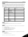
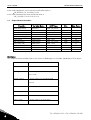
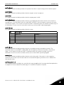
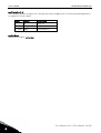
user's manual
nxs/p frequency converters
l o n w o r k s ®
o p t i o n b o a r d
o p t - c 4
INDEX
1.
GENERAL ........................................................................................................................... 3
2.
LonWorks OPTION BOARD TECHNICAL DATA .................................................................... 4
2.1 General ............................................................................................................................................ 4
2.2 Physical media and wiring .............................................................................................................. 5
2.3 Profiles............................................................................................................................................. 6
3.
LonWorks FIELDBUS BOARD LAYOUT AND CONNECTIONS .............................................. 7
LonWorks OPT-C4 option board ..................................................................................................... 7
Grounding of bus cable shield in OPT-C4....................................................................................... 8
Bus termination resistors ............................................................................................................. 10
LED indications.............................................................................................................................. 10
3.1
3.2
3.3
3.4
4.
INSTALLATION OF VACON NX LonWorks BOARD ............................................................. 12
4.1 Board information sticker ............................................................................................................. 14
5.
COMMISSIONING.............................................................................................................. 15
5.1 Fieldbus board parameters .......................................................................................................... 15
5.2 Start-up test .................................................................................................................................. 16
6.
LonWorks INTERFACE ..................................................................................................... 17
General .......................................................................................................................................... 17
Input Network Variables ............................................................................................................... 19
Output Network Variables............................................................................................................. 22
Network Configuration Variables ................................................................................................. 25
Process data .................................................................................................................................. 27
6.1
6.2
6.3
6.4
6.5
7.
FAULT TRACKING............................................................................................................. 28
8.
APPENDIX 1...................................................................................................................... 29
general
1.
vacon • 3
GENERAL
Vacon NX frequency converters can be connected to the LonWorks® network using a fieldbus board.
The converter can then be controlled, monitored and programmed from the Host system.
The LonWorks® board shall be installed in slot E on the control board of the frequency converter.
LONWORKS technology has been developed by Echelon Corporation. LONWORKS network is used in
applications like industry and building automation, controlling household electronics, medical
instrumentation and many others. The target of the LONWORKS network is to provide a common
vendor independent communication network for intelligent devices.
In a LONWORKS network, no central control or master-slave architecture is needed. Nodes on a
network communicate with each other using LonTalk® protocol. Interoperable nodes use Standard
Network Variable Types (SNVT) for communicating over the network. The definition of an SNVT
includes units, a range, and an increment. Vacon option board uses only Standard Network Variable
Types for the data types.
All network variables are either input (data is coming from the network to the device) or output (data
is sent to the network by the device) network variables. When network variables on different nodes on
the network have been bound together by an installation tool, passing of data is automatic between
the right nodes. Only the same type of network variables can be bound together, so it is very
important to have compatible interfaces.
Internal components and circuit boards are at high potential when the frequency
converter is connected to the power source. This voltage is extremely dangerous
and may cause death or severe injury if you come into contact with it.
WARNING!
24-hour service: +358-40-8371 150 • Email: [email protected]
1
4 • vacon
technical data
2.
LONWORKS OPTION BOARD TECHNICAL DATA
2.1
General
LonWorks
connections
Communications
Environment
Interface
Pluggable connector (5 mm)
Channel type
Transfer cable
Baud rate
Ambient operating
temperature
Storing
temperature
Humidity
Altitude
Vibration
TP/FT-10
Twisted pair
78 Kbit/s
–10°C…50°C
Safety
Table 2-1. LonWorks technical data
2
–40°C…70°C
<95%, no condensation allowed
Max. 1000 m
0.5 G at 9…200 Hz
Fulfils EN50178 standard
Tel: +358-201-2121 • Fax: +358-201-212 205
technical data
2.2
vacon • 5
Physical media and wiring
LONWORKS networks can be implemented on many different physical media. Vacon OPTC4 option board is equipped with an FT-X1 transceiver supporting the Free Topology
transformer coupled network, which allows the network wire to be connected as bus,
star, loop or combination of these. This media reaches a communication speed of
78kBits/s. The FT-X1 transceiver is compatible with Echelon’s LPT-10 Link Power
Transceiver, and these transceivers can communicate with each other on a single
twisted pair cable.
termination
termination
Figure 2-1. Doubly Terminated Bus Topology
termination
Figure 2-2. Singly Terminated Bus Topology
termination
Figure 2-3. Star Topology
termination
Figure 2-4. Loop Topology
Up to 64 FTT-10 transceiver nodes are allowed per network segment, the individual segments
can be connected together by a router. See Table 3-1 for recommended cable types and cable
lengths for FTT-10. Even if unshielded cable types are recommended to be used with this type
of transceiver, it is still highly recommended to use only shielded cables with frequency
24-hour service: +358-40-8371 150 • Email: [email protected]
2
6 • vacon
technical data
converters. Attention should be paid to proper grounding of the shield to ensure bus
operation. Grounding of the shield should be done at both ends of the cable.
Cable type
2.3
Max. doubly
terminated
bus length
Max. free
topology
wire length
Max. node-to-node
distance
Belden 85102 (unshielded)
2700 m
500 m
500 m
Belden 8471
LONAK 2x1,3 (unshielded)
2700 m
500 m
400 m
Level IV, 22AWG
LONAK 2x2x0,65 (unshielded)
1400 m
500 m
400 m
JY (St) Y 2x2x0.8mm
900 m
500 m
LONAK 2x2x0,8 (shielded)
Table 2-2. Line length for different transmission speeds
320 m
Profiles
LonMark Functional Profiles describe in detail the application layer interface, including the network
variables, configuration properties, and default and power-up behaviors required on LonMark devices
for specific, commonly used control functions.
2.3.1
Variable Speed Drive Profile
Leading manufacturers of drive technology have jointly defined the LonMark profile. The profile
specifies how the drives are to be parameterized and how the setpoints and actual values are to be
transmitted. This enables drives from different vendors to be exchanged. The profile contains
necessary specifications for speed control and positioning. It specifies the basic drive functions while
leaving sufficient freedom for application-specific expansions and further developments.
2
Tel: +358-201-2121 • Fax: +358-201-212 205
layout and connections
3.
vacon • 7
LONWORKS FIELDBUS BOARD LAYOUT AND CONNECTIONS
Vacon LonWorks Fieldbus Board is connected to the fieldbus through 3-pin pluggable bus connector.
The communication with the control board takes place through the standard Vacon Interface Board
Connector.
3.1
LonWorks OPT-C4 option board
H3
H2
H1
X5
21
22
23
lw1.fh8
Figure 3-1. Vacon LonWorks option board OPT-C4
Signal
Connector
A1
21
Data
A2
22
Data
0Shield
23
Shield
Table 3-1. OPT-C4 bus connector signals
24-hour service: +358-40-8371 150 • Email: [email protected]
Description
3
8 • vacon
3.2
layout and connections
Grounding of bus cable shield in OPT-C4
The bus cable shield can be grounded to the frame of the frequency converter through an RC filter
located on the OPT-C4 board.
Note: Normally, the option board has already been installed in slot E of the control board. It is not
necessary to detach the whole board for the grounding of the bus cable shield. Just detach the
terminal block.
3.2.1
Grounding the bus cable shield directly to the frequency converter frame using the RCfilter
1
Strip about 5 cm of the cable as
shown in the picture.
Figure 3-2.
2
Leave no more than 7 mm of the
data cable outside the terminal
block (Figure 3-3) and strip the data
cables at about 5 mm to fit in the
terminals (Figure 3-4).
Figure 3-3.
3
Tel: +358-201-2121 • Fax: +358-201-212 205
layout and connections
vacon • 9
Figure 3-4.
3
Insert the data cables and the
shield in their respective
terminals. See Table 3-1.
Figure 3-5.
4
If the LonWorks board was
detached from the control unit
place it into slot E of the control
board (see board installation on
page 12). Otherwise attach the
terminal block. Fix the cable on
the frame with the clamp.
Figure 3-6.
24-hour service: +358-40-8371 150 • Email: [email protected]
3
10 • vacon
3.3
layout and connections
Bus termination resistors
To assure a proper data transmission, termination of the network segments is required. Depending
on the type of network, either one or two terminations are necessary. Free topology network segment
requires only one termination whereas a doubly terminated bus topology requires two.
The jumper X5 on the Vacon LonWorks board must be set accordingly. Use 94-ohm termination
resistance when only one termination is needed and 47-ohm for two terminations.
H3
H2
H1
47Ω
94Ω
no termination
X5
21
22
23
X5
lw1.fh8
Figure 3-7. Using jumper X5 to set the bus termination.
3.4
LED indications
The three LED indications next to the connector show the present statuses of the Neuron (green H3),
the LonWorks board (yellow H2) and the Fieldbus Module (green H1). From the user's viewpoint, the
first two are the most significant.
Figure 3-8. LED indications on the LonWorks board
H3
H2
H1
X5
21
22
23
lw1.fh8
H3
H2
H1
3
Neuron Service LED
Board Status
Bus Status
GREEN
YELLOW
GREEN
Tel: +358-201-2121 • Fax: +358-201-212 205
layout and connections
Neuron status (H3)
LED is:
OFF
ON
Flashing
GREEN
Meaning:
Configured
Applicationless and Unconfigured
Unconfigured
Board status LED (H2)
LED is:
OFF
ON
Blinking fast
(once/1 s)
Blinking slow
(once/5 s)
vacon • 11
State Code
4
3
2
YELLOW
Meaning:
Option board not activated
Option board in initialisation state waiting for activation command from the
frequency converter
Option board is activated and in RUN state
Option board is ready for external communication
Option board is activated and in FAULT state
Internal fault on option board
Bus status LED (H1) GREEN
LED is:
OFF
ON
Blinking very
fast for 5s
(once/0.2 s)
Blinking fast
(once/1 s)
Blinking slow
(once/5 s)
Meaning:
Fieldbus module is waiting for parameters from the frequency converter
No external communication
Fieldbus module is activated
Parameters received and module activated
Module is waiting for messages from the bus
Fieldbus module has received a wink request.
Module is activated and receiving messages from the bus
Module is in FAULT state
No messages from Net within the watchdog time
Bus broken, cable loose
24-hour service: +358-40-8371 150 • Email: [email protected]
3
12 • vacon
4.
installation
INSTALLATION OF VACON NX LONWORKS BOARD
!
MAKE SURE THAT THE FREQUENCY CONVERTER IS SWITCHED OFF BEFORE
AN OPTION OR FIELDBUS BOARD IS CHANGED OR ADDED!
NOTE
4
A
Vacon NX frequency converter
B
Remove the cable cover.
C
Open the cover of the control unit.
Tel: +358-201-2121 • Fax: +358-201-212 205
installation
D
vacon • 13
Install LonWorks option board in slot E
on the control board of the frequency
converter. Make sure that the grounding
plate (see below) fits tightly in the
clamp.
H3
H2
H1
X5
21
22
23
lw1.fh8
E
Make a sufficiently wide opening for
your cable by cutting the grid as wide as
necessary.
F
Close the cover of the control unit and
the cable cover.
24-hour service: +358-40-8371 150 • Email: [email protected]
4
14 • vacon
4.1
installation
Board information sticker
The LonWorks option board package delivered by the factory includes a sticker (shown below). Please
mark the board type (1), the slot into which the board is mounted (2) and the mounting date (3) on the
sticker. Finally, attach the sticker on your drive.
1
3
Drive modified:
Option board:
NXOPT................ Date:...................
in slot:
A B C D E
IP54 upgrade/Collar
Date:...................
EMC level modified: H T / T
H Date:...................
2
4
Tel: +358-201-2121 • Fax: +358-201-212 205
commissioning
5.
vacon • 15
COMMISSIONING
READ FIRST CHAPTER 8 'COMMISSIONING' IN VACON NX USER'S MANUAL (Document nr. ud00701,
please visit http://www.vacon.com/support/documents.html).
5.1
Fieldbus board parameters
The Vacon LonWorks board is commissioned with the control keypad by giving values to appropriate
parameters in menu M7 (for locating the expander board menu, see Vacon NX User's Manual,
Chapter 7).
Expander board menu (M7)
The Expander board menu makes it possible for the user 1) to see what expander boards are
connected to the control board and 2) to reach and edit the parameters associated with the expander
board.
Enter the following menu level (G#) with the Menu button right. At this level, you can browse through
slots A to E with the Browser buttons to see what expander boards are connected. On the lowermost
line of the display you also see the number of parameter groups associated with the board.
If you still press the Menu button right once you will reach the parameter group level including one
parameter (Service pin).
LonWorks parameters
To commission the LonWorks board, enter the parameter G7.5.1.1 from the Parameters group
(G7.5.1). Give the desired value to the LonWorks parameter.
#
1
Name
Service Pin
Default
0
Range
0..1
Description
Broadcasts a service pin message to the
network.
Table 5-1. LonWorks parameters
24-hour service: +358-40-8371 150 • Email: [email protected]
5
16 • vacon
5.2
commissioning
Start-up test
Frequency converter application
Choose Fieldbus (Bus/Comm) for the active control place (see Vacon NX User's Manual, Chapter
7.3.3).
Master software
1. Write 100.0 1 to nviDrvSpeedStpt.
2. Frequency converter status is RUN and output frequency is 1.00 * nviDrvSpeedScale
3. Write 0.0 0 to nviDrvSpeedStpt
4. Frequency converter status is STOP.
If nvoDrvStats bit 3 = 1 Status of frequency converter is FAULT.
5
Tel: +358-201-2121 • Fax: +358-201-212 205
lonworks interface
6.
vacon • 17
LONWORKS INTERFACE
Features of the LonWorks interface:
• Direct control of Vacon NX (e.g. Run, Stop, Direction, Speed reference, Fault reset)
• Full access to all Vacon NX parameters
• Monitor Vacon NX status (e.g. Output frequency, Output current, Fault code)
6.1
General
Node Object:0
nv1
nviRequest
SNVT_obj_request
Mandatory
Network
Variables
nv2
nvoStatus
SNVT_obj_status
Figure 6-1. The Node object diagram.
24-hour service: +358-40-8371 150 • Email: [email protected]
6
18 • vacon
lonworks interface
nv1
nv2
nviDrvSpeedStpt
SNVT_switch
nviDrvSpeedScale
SNVT_lev_percent
Variable Speed Motor Drive:
6010
Mandatory
nvoDrvSpeed
nv4
Network
SNVT_levPercent
Variables
Optional
Network
Variables
nv3
nvoDrvCurnt
SNVT_amp
nv6
nvoDrvPwr
SNVT_power_kilo
nv7
nvoDrvRunHours
SNVT_time_hour
nv27
nvoDrvStatus
SNVT_state
nv28
nvoDrvEnrgy
SNVT_elect_kWh
nv29
nvoActFault
SNVT_count
Configuration Properties
nc50
nc53
nc48
nc49
nc52
nc158
nc159
nc160
nc161
nc162
nciMaxSpeed
nciMinSpeed
nciRcvHrtBt
nciSndHrtBt
nciMinOutTm
nciNmlSpeed
nciNmlFreq
nciRampUpTm
nciRampDownTm
nciDrvSpeedScale
nv8
nviRstFault
SNVT_switch
nv9
nviClrCntr
SNVT_switch
nv10
nviProcessIN1
SNVT_lev_percent
nv11
nviProcessIN2
SNVT_lev_percent
nv30
nvoProcessOut1
SNVT_lev_percent
nv12
nviProcessIN3
SNVT_lev_percent
nv31
nvoProcessOut2
SNVT_lev_percent
nv13
nviProcessIN4
SNVT_lev_percent
nv32
nvoProcessOut3
SNVT_lev_percent
nv14
nviProcessIN5
SNVT_lev_percent
nv33
nvoProcessOut4
SNVT_lev_percent
nv15
nviProcessIN6
SNVT_lev_percent
nv34
nvoProcessOut5
SNVT_lev_percent
nv16
nviProcessIN7
SNVT_lev_percent
nv35
nvoProcessOut6
SNVT_lev_percent
nv17
nviProcessIN8
SNVT_lev_percent
nv36
nvoProcessOut7
SNVT_lev_percent
nv18
nviDigitalIn1
SNVT_switch
nv37
nvoProcessOut8
SNVT_lev_percent
nv19
nviDigitalIn2
SNVT_switch
nv38
nvoDigitalOut1
SNVT_switch
nv20
nviDigitalIn3
SNVT_switch
nv39
nvoDigitalOut2
SNVT_switch
nv21
nviDigitalIn4
SNVT_switch
nv40
nvoDigitalOut3
SNVT_switch
nv22
nviDigitalIn5
SNVT_switch
nv41
nvoDigitalOut4
SNVT_switch
nv23
nviDigitalIn6
SNVT_switch
nv42
nvoDigitalOut5
SNVT_switch
nv24
nviDigitalIn7
SNVT_switch
nv43
nvoDigitalOut6
SNVT_switch
nv25
nviDigitalIn8
SNVT_switch
nv44
nvoDigitalOut7
SNVT_switch
nv26
nviParCmd
SNVT_preset
nv45
nvoDigitalOut8
SNVT_switch
nv46
nvoParResp
SNVT_preset
Manufacturer
Defined
Network
Variables
Figure 6-2. The Variable Speed Motor Drive object diagram.
6
Tel: +358-201-2121 • Fax: +358-201-212 205
lonworks interface
6.2
vacon • 19
Input Network Variables
Function
Variable Name
SNVT type
Min.
Value
Max.
Value
n/a
n/a
-163.840%
163.830%
Node Object request
nviRequest
SNVT_obj_request
Driver speed setpoint
nviDrvSpeedStpt
SNVT_switch
Driver set point speed
scaling
nviDrvSpeedScale
SNVT_lev_percent
Reset fault
nviRstFault
SNVT_switch
n/a
n/a
Clear kWh trip or Drive
total running hours
trip counters
nviClrCntr
SNVT_switch
1
2
Process In Data
nviProcessIn1..8
SNVT_lev_percent
0
65535
Digital Inputs
nviDigitalIn1..8
SNVT_switch
0
4
Parameter Set
nviParCmd
SNVT_preset
n/a
n/a
Table 6-1. Network input variables
nviRequest
This input network variable provides the mechanism to request a particular mode for the Node object
or the Variable Speed Motor Drive object within a node. Supported requests are RQ_NORMAL,
RQ_UPDATE_STATUS, RQ_CLEAR_STATUS, RQ_REPORT_MASK, RQ_DISABLED, RQ_ENABLE and
RQ_CLEAR_ALARM.
nviDrvSpeedStpt
This input network variable provides control and a low resolution speed setpoint
state
value
command
0
NA
Stop
1
0
0%
1
1 to 200
0.5 to 100%
1
201 to 255
100.0%
NA
Auto
0xFF
Table 6-2.
nviDrvSpeedScale
This input netork variable provides scaling for nviDrvSpeedStpt. Negative values indicate a motor
direction in reverse. For example, if the nviDrvSpeedStpt value is 50% and nviDrvSpeedScale -150%,
then the actual speed setpoint is –75%, or 0.75 times the nominal speed in reverse direction. The valid
range is –163,840% to 163,830. The value 0x7FFF (+163,835%) will be handled as an invalid value.
Default value is determined by nciDrvSpeedScale. This value will be adopted at power-up and in case
of not receiving an update within the specified Receive Heartbeat time.
24-hour service: +358-40-8371 150 • Email: [email protected]
6
20 • vacon
lonworks interface
nviRstFault
This input network variable provides a fault reset. Setting value 1 for State and a non-zero value for
Value will reset an active fault in Vacon NX. Default value is 0; 0.
State
Value
Command
0
any
no action (0; 0)
1
0
no action (0; 1)
1
>0
reset fault (200 ; 0)
any
invalid (no action)
-1 (0xFF)
Table 6-3.
nviClrCntr
This input network variable provides a mechanism to clear the kWh trip counter or the Drive total
running hours trip counter.
1
MWh trip counter
2
Operation day trip counter
nviProcessIn1..8
These input network variables are sent directly to the application (see more detailed explanation in
chapter 6.5 Process data) The valid range is 0 to 65535 (-163,840 to 163,835).
nviDigitalIn1..8
These input network variables are sent directly to the application (see more detailed explanation in
chapter 6.5 Process data) Default value is 0; 0.
state
value
command
0
any
off (0; 0)
1
0
off (0; 1)
1
>0
on (200; 1)
any
invalid (no action)
-1 (0xFF)
Table 6-4.
6
Tel: +358-201-2121 • Fax: +358-201-212 205
lonworks interface
vacon • 21
nviParCmd
This input network variable is used to read and write the parameters. The parameter addresses are
determined in the application. Every parameter and actual value has been given an ID number in the
application. The ID numbering of the parameter as well as the parameter ranges and steps can be
found in the application manual in question. The parameter value must be given without decimals.
Find the ID numbers of each parameter/actual value in the application manual. The ID numbers are
grouped as follows:
Parameter ID
Group
0
Not used
1 … 98
Actual Values
99
Active Fault Code
100
Not Used
101… 899
Parameter
900 … 999
Reserved
Description
Reserved for LonWorks board internal
usage
1000
Not Used
1001…1999
Parameter
Table 6-5. Grouping of ID numbers
Examples
Data format in examples is:
- learn selector <byte(3) byte(2) byte(1) byte(0)> day hour minute second millisecond
x = meaningless.
Example1
Write to parameter number 102 (Max frequency “Basic Application par. ID102”) value 4500 (45Hz).
Write command to nviParSet
- LN_LEARN_CURRENT 102 <x x 11 94> x x x x
If the write command is successful then nvoParOut value is
- LN_LEARN_CURRENT 102 <0 0 11 94> 0 0 0 0
If the write command fails then nvoParOut value is
- LN_NUL 102 <0 0 11 94> 0 0 0 0
Example2
Read parameter number 112 (Nominal speed of the motor “Basic Application par. ID112”) default
value 1440 (1440 rpm).
Read command to nviParSet
- LN_RECALL 112 <x x x x> x x x x
24-hour service: +358-40-8371 150 • Email: [email protected]
6
22 • vacon
lonworks interface
If the read command is successful then nvoParOut value is
- LN_RECALL 112 <0 0 5 A0> 0 0 0 0
If the read command fails then nvoParOut value is
- LN_ LN_NUL 112 <0 0 0 0> 0 0 0 0
6.3
Output Network Variables
Function
Variable Name
Node Object status
Drive speed feedback
Actual motor current
Actual drive power
Drive total running hours
nvoStatus
nvoDrvSpeed
nvoDrvCurnt
nvoDrvPwr
nvoDrvRunHours
nvoDrvStatus
nvoDrvEnrgy
nvoActFault
nvoProcessOut1..8
nvoDigitalOut1..8
nvoParResp
Status word
kWh trip counter
Active fault code
Process Out
Digital Out
Parameter Out
SNVT type
SNVT
SNVT
SNVT
SNVT
SNVT
SNVT
SNVT
SNVT
SNVT
SNVT
SNVT
obj status
lev percent
amp
power kilo
time hour
state
elect kwh
count
lev percent
switch
preset
Min.
Max. Value
-163.840%
0.0A
0,0 kW
0h
n/a
0kWh
0
0
0
-
+163.830%
3276.7A
6553,5 kW
65535
n/a
65535kWh
41
65535
4
-
Table 6-6. Network output variables
NvoStatus
This output network variable reports the status for Node object or Variable Speed Motor Drive object.
Field
Description
object_id
ID of object within node
invalid_id
1 means requested ID is not implemented
in this node
invalid_request
1 means request for unimplemented
function
disabled
1 means object disabled
electrical_fault
1 means drive is faultefd
in_alarm
1 means drive is in alarm
report_mask
1 means status is an event mask
Table 6-7.
6
Tel: +358-201-2121 • Fax: +358-201-212 205
lonworks interface
vacon • 23
nvoDrvSpeed
This output network variable provides the speed of the drive as a percentage of the nominal speed.
nvoDrvCurnt
This output network variable provides the drive output current in amperes.
nvoDrvPwr
This output network variable provides the drive output power in kW.
nvoDrvRunHours
This output network variable provides the drive resettable operation time counter for the motor in
running hours. The maximum value for used SNVT is 65535 h. On the frequency converter the value
can go much higher. If the counter exceeds the SNVT’s maximum value, the network variable stays at
its maximum. In such cases the real value can be seen on Vacon NX’s operating keypad.
nvoDrvStatus
This output network variable provides the drive status.
Bit
Description
Value = 0
Not Ready
0
1
FC stopped
2
Clockwise
3
No fault
4
No warning
5
Reference ≠ Actual value
Table 6-8. Status word bit descriptions
Value = 1
Ready
Running
Counterclockwise
Fault active
Warning active
Reference = Actual value
nvoDrvEnrgy
This output network variable provides the drive resettable energy consumption counter. The
maximum value for used SNVT is 65535 kWh. On the frequency converter the value can go much
higher. If the counter exceeds the SNVT’s maximum value, the network variable stays at its
maximum. In such cases the real value can be seen on Vacon NX’s operating keypad.
nvoActFault
This output network variable provides the drive active fault code. If the value is 0 the frequency
converter has no fault. See the fault code list in Vacon NX Frequency Converter User’s Manual for
fault identification.
nvoProcessOut1..8
These output network variables are sent directly from the application (see more detailed explanation
in chapter 6.5 Process data) The valid range is 0 to 65535 (-163,840 to 163,835).
24-hour service: +358-40-8371 150 • Email: [email protected]
6
24 • vacon
lonworks interface
nvoDigitalOut1..8
These output network variables are sent directly from the application (see more detailed explanation
in chapter 6.5 Process data).
state
value
command
0
0
off (0; 0)
1
200 (0xC8)
on (200; 1)
any
invalid (NULL)
-1 (0XfF)
Table 6-9.
nvoParResp
explained in chapter nviParSet.
6
Tel: +358-201-2121 • Fax: +358-201-212 205
lonworks interface
6.4
vacon • 25
Network Configuration Variables
Function
Variable Name
SNVT type
Maximum motor speed
nciMaxSpeed
SCPTmaxSetpoint
Minimum motor speed
nciMinSpeed
SCPTminSetpoint
Receive heartbeat time
nciRcvHrtBt
SCPTmaxRcvTime
Send heartbeat time
nciSndHrtBt
SCPTmaxSndTime
Minimum output time
nciMinOutTime
SCPTminSndTime
Nominal motor speed in RPM
nciNmlSpeed
SCPTnomRPM
Nominal motor frequency
nciNmlFreq
SCPTnomFreq
Minimum ramp up time
nciRampUpTm
SCPTrampUpTm
Minimum ramp down time
nciRampDownTm
SCPTrampDownTm
Default value for nviDrvSpeedScale
nciDrvSpeedScale
SCPTdefScale
Table 6-10. Network configuration variables
nciMaxSpeed
This configuration property is used to define the maximum speed of a motor. The value is entered as a
percentage of nominal speed in RPM, as defined by the Nominal Speed (nciNmlSpeed) configuration
value. The value of the maximum speed must be validated against the value of the minimum speed as
follows:
-163.840 < minimum speed < maximum speed < 163.830
nciMinSpeed
This configuration property is used to define the minimum speed of the motor. The value is entered as
a percentage of nominal speed in RPM, as defined by the Nominal Speed (nciNmlSpeed) configuration
value. The value of the minimum speed must be validated against the value of the maximum speed as
follows:
-163.840 < minimum speed < maximum speed < 163.830
nciRcvHrtBt
This configuration property is used to control the maximum time that elapses after the last update of
the network variables nviDrvSpeedStpt or nviDrvSpeedScale before the VSD object starts to use the
default values.
nciSndHrtBt
This configuration property defines the maximum period that expires before the network variables
nvoDrvSpeed, nvoDrvCurnt and nvoDrvPwr are automatically updated.
24-hour service: +358-40-8371 150 • Email: [email protected]
6
26 • vacon
lonworks interface
nciMinOutTime
This configuration property defines the minimum period of automatic network variable tansmission.
nciNmlSpeed
This configuration property is used to provide the nominal speed of the motor in RPM. This value is
necessary to determine the minimum and maximum speeds for the motor, based on the configuration
properties nciMinSpeed, nciMaxSpeed (entered as a percentage of nominal speed).
nciNmlFreq
This configuration property is used to provide the nominal frequency for the motor.
nciRampUpTm
Defines the acceleration time for Vacon NX. The valid range is 0.0 to 6,553.4 sec (0.1 sec).
nciRampDownTm
Defines the deceleration time for Vacon NX. The valid range is 0.0 to 6,553.4 sec (0.1 sec).
nciDrvSpeedScale
This configuration property is used as the default value for nviDrvSpeedScale. This value will be
adopted at power-up and in case no input variable within the specified Receive Heartbeat time is
received.
6
Tel: +358-201-2121 • Fax: +358-201-212 205
lonworks interface
6.5
vacon • 27
Process data
Aplication
FBProcessDataIn1..8
LonWorks
nviProcessIn1..8
nviDigitaln 1
bit 3
nviDigitaln 2
bit 4
nviDigitaln 3
bit 5
nviDigitaln 4
bit 6
nviDigitaln 5
bit 7
nviDigitaln 6
bit 10
nviDigitaln 7
bit 11
nviDigitaln 8
bit 12
nvoProcessOut1..8
FBFixedControlWord
FBProcessDataOut1..8
nvoDigitaOut 1
bit 0
nvoDigitaOut 2
bit 1
nvoDigitaOut 3
bit 2
nvoDigitaOut 4
bit 3
nvoDigitaOut 5
bit 4
nvoDigitaOut 6
bit 5
nvoDigitaOut 7
bit 6
nvoDigitaOut 8
bit 7
FBGeneralStatusWord
Figure 6-3. Control of frequency converter through LonWorks
24-hour service: +358-40-8371 150 • Email: [email protected]
6
28 • vacon
7.
fault tracking
FAULT TRACKING
The table below presents the faults related to the LonWorks option board. For more information, see
also Vacon NX User's Manual, Chapter 9.
The LonWorks option board status LEDs are described in more detail in Chapter 3.4.
Fault
code
37
38
39
40
Fault
Possible cause
Correcting measures
Option board changed.
Option board added.
Option board removed.
Unknown option board.
Reset
Reset
Reset
53
Device change
Device added
Device removed
Device
unknown
Fieldbus fault
The received heartbeat time has expired.
54
Slot fault
Defective option board or slot
Check the installation.
If installation is correct contact the
nearest Vacon distributor.
Please visit:
http://www.vacon.com/wwcontacts.h
tml
Check the board and slot.
Contact the nearest Vacon
distributor.
Please visit:
http://www.vacon.com/wwcontacts.h
tml
Table 7-1. LonWorks option board faults
You can define with parameters how the frequency converter shall react to certain faults:
Code
Parameter
Min
Max
P2.7.22
Response to fieldbus
fault
0
P2.7.23
Response to slot
fault
0
Unit
Step
Default
ID
3
1
0
733
3
1
0
734
Note
0=No response
1=Warning
2=Fault,stop acc. to 2.4.7
3=Fault,stop by coasting
0=No response
1=Warning
2=Fault,stop acc. to 2.4.7
3=Fault,stop by coasting
Table 7-2. Frequency converter responses to faults
6
Tel: +358-201-2121 • Fax: +358-201-212 205
appendix
8.
vacon • 29
APPENDIX 1
Process Data OUT
The nodes can read the frequency converter’s actual values using process data variables.
Basic, Standard, Local/Remote, Multi-Step, PID control and Pump and fan control applications use
process data as follows:
Data
Process data OUT 1
Process data OUT 2
Process data OUT 3
Process data OUT 4
Process data OUT 5
Process data OUT 6
Process data OUT 7
Process data OUT 8
Value
Output Frequency
Motor Speed
Motor Current
Motor Torque
Motor Power
Motor Voltage
DC link voltage
Active Fault Code
Unit
Hz
rpm
A
%
%
V
V
-
Scale
0,01 Hz
1 rpm
0,1 A
0,1 %
0,1 %
0,1 V
1V
-
The Multipurpose Control Application has a selector parameter for every Process Data. The
monitoring values and drive parameters can be selected using the ID number (see NX All in One
Application Manual, Tables for monitoring values and parameters). Default selections are as in the
table above.
Process Data IN
Process Data is used with All-inOne applications as follows:
Basic, Standard, Local/Remote, Multi-Step applications
Data
PD1 – PD8
Value
Not used
Unit
-
Step
-
Value
Torque Reference
Free Analogue INPUT
Adjust Input
Not Used
Unit
%
%
%
-
Step
0.1%
0.01%
0.01%
-
Multipurpose control application
Data
Process Data IN1
Process Data IN2
Process Data IN3
PD3 – PD8
24-hour service: +358-40-8371 150 • Email: [email protected]
8
30 • vacon
appendix
PID control and Pump and fan control applications
Data
Value
Process Data IN1 Reference for PID
controller
Process Data IN2 Actual Value 1 to PID
controller
Process Data IN3 Actual Value 2 to PID
controller
PD4–PD8
Not Used
7
Unit
%
Step
0.01%
%
0.01%
%
0.01%
-
-
Tel: +358-201-2121 • Fax: +358-201-212 205
head office and production:
production:
Vaasa
Vacon Plc
Runsorintie 7
65380 Vaasa
[email protected]
telephone: +358 (0)201 2121
fax: +358 (0)201 212 205
Suzhou, China
Vacon Suzhou Drives Co. Ltd.
Building 13CD
428 Xinglong Street
Suchun Industrial Square
Suzhou 215126
telephone: +86 512 6283 6630
fax: +86 512 6283 6618
Vacon Traction Oy
Vehnämyllynkatu 18
33580 Tampere
telephone: +358 (0)201 2121
fax: +358 (0)201 212 710
sales companies and representative offices:
finland
Helsinki
Vacon Plc
Äyritie 12
01510 Vantaa
telephone: +358 (0)201 212 600
fax: +358 (0)201 212 699
Tampere
Vacon Plc
Vehnämyllynkatu 18
33580 Tampere
telephone: +358 (0)201 2121
fax: +358 (0)201 212 750
austria
Vacon AT Antriebssysteme GmbH
Aumühlweg 21
2544 Leobersdorf
telephone: +43 2256 651 66
fax: +43 2256 651 66 66
belgium
Vacon Benelux NV/SA
Interleuvenlaan 62
3001 Heverlee (Leuven)
telephone: +32 (0)16 394 825
fax: +32 (0)16 394 827
china
Vacon Suzhou Drives Co. Ltd.
Beijing Office
A205, Grand Pacific Garden Mansion
8A Guanhua Road
Beijing 100026
telephone: +86 10 6581 3734
fax: +86 10 6581 3754
france
Vacon France
ZAC du Fresne
1 Rue Jacquard – BP72
91280 Saint Pierre du Perray CDIS
telephone: +33 (0)1 69 89 60 30
fax: +33 (0)1 69 89 60 40
Vacon distributor:
germany
Vacon GmbH
Gladbecker Strasse 425
45329 Essen
telephone: +49 (0)201 806 700
fax: +49 (0)201 806 7099
india
Vacon India
Flat no T1, 3rd floor
VNS Ashok Apartment
Plot no. 9A, New Beach Road
Thiruvanmiyur
Chennai-600041
Tel. +91 44 245 150 18
italy
Vacon S.p.A.
Via F.lli Guerra, 35
42100 Reggio Emilia
telephone: +39 0522 276811
fax: +39 0522 276890
the netherlands
Vacon Benelux BV
Weide 40
4206 CJ Gorinchem
telephone: +31 (0)183 642 970
fax: +31 (0)183 642 971
norway
Vacon AS
Langgata 2
3080 Holmestrand
telephone: +47 330 96120
fax: +47 330 96130
russia
ZAO Vacon Drives
Bolshaja Jakimanka 31,
109180 Moscow
telephone: +7 (095) 974 14 47
fax: +7 (095) 974 15 54
ZAO Vacon Drives
2ya Sovetskaya 7, office 210A
191036 St. Petersburg
telephone: +7 (812) 332 1114
fax: +7 (812) 279 9053
spain
Vacon Drives Ibérica S.A.
Miquel Servet, 2. P.I. Bufalvent
08243 Manresa
telephone: +34 93 877 45 06
fax: +34 93 877 00 09
sweden
Vacon AB
Torget 1
172 67 Sundbyberg
telephone: +46 (0)8 293 055
fax: +46 (0)8 290 755
thailand
Vacon South East Asia
335/32 5th-6th floor
Srinakarin Road, Prawet
Bangkok 10250
Tel. +66 (0)85 100 7090
united arab emirates
Vacon Middle East and Africa
Block A, Office 4A 226
P.O.Box 54763
Dubai Airport Free Zone
Dubai
Tel. +971 (0)4 204 5200
Fax: +971 (0)4 204 5203
united kingdom
Vacon Drives (UK) Ltd.
18, Maizefield
Hinckley Fields Industrial Estate
Hinckley
LE10 1YF Leicestershire
telephone: +44 (0)1455 611 515
fax: +44 (0)1455 611 517