1
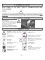
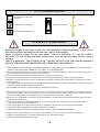
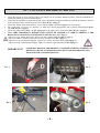
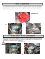
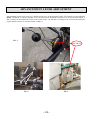
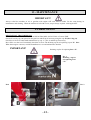
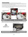
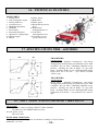
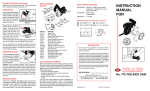
06/07
GB
FLAIL MOWER
USER’S MANUAL
TR60 – TR80 HYDRO
INDEX
1.
FOREWORD
Pag. 0
2.
IDENTIFICATION AND MARKING
Pag. 0
3.
CONDITIONS AND USE
Pag. 1
4.
WARRANTY
Pag. 1
5.
MACHINE STARTING
Pag. 2
READ THIS MANUAL CAREFULLY
6.
PACKAGE OPENING
Pag. 2
All right reserved
7.
WARNING SIGNS
Pag. 2
8.
CONTROL SIGNS
Pag .3
9.
SAFETY WARNINGS
Pag. 3
This manual cannot be either reproduced or released without the
manufacturer’s prior written consent.
PRINTED IN ITALY
1 - FOREWORD
This symbol is used to highlight an important safety information. If
this information is ignored, people are in danger either of possible
injures – even serious ones – or death.
IMPORTANT
This term highlights special precautions to be taken in order not to
damage the machine.
10. CAUTIONS BEFORE STARTING
Pag.6
11. ENGINE START UP
Pag. 7
12. ADJUSTMENTS
Pag. 9
13. MAINTENANCE
Pag. 12
14. ASSEMBLY AND DISASSEMBLY
Pag. 13
15. TRANSPORT
Pag.13
16. TECHNICAL FEATURES
Pag. 14
17. SPECIFICATIONS TR80-60 Hydro
Pag. 14
18. AIRY NOISE AND VIBRATIONS
Pag. 14
ENGINE :Use and maintenance instructions of the engine
are mentioned in the relevant manual, copy of which is
always supplied with every machine.
2 – IDENTIFICATION AND MARKING
The machine serial number is printed on the drive box.
IMPORTANT NOTE
Always mention the machine serial number when calling our technical service or when ordering spare parts.
MARKING
The CE mark is on the engine support right side.
Marking example.
3-CONDITIONS AND USE
This manual gives you general information on how this
machine should be used and maintained. For any technical
problem, please, call Your confidential dealer.
•
This machine has been designed to be used in
compliance with what specified in the machine
descriptions and safety warnings of this instructions
manual.
•
Any other use is not allowed. The manufacturer is
not responsible for damages caused by any use then
the intended use. The user is fully responsible for
any possible risk.
•
Use, maintenance and repair clauses prescribed by
the manufacturer are also integral part of the
machine intended use.
•
Only people familiar with this machine and well
aware of its hidden risks can use, repair and
maintain it.
•
The manufacturer is not responsible for damages
caused by non-authorized changes made on this
machine.
•
Besides warnings mentioned in this manual, please,
also comply with general regulations on safety and
accident prevention of EEC and the country in
which this machine will be operating.
4-WARRANTY
If in doubt on causes and possible solutions for a certain
trouble, please, call our authorized dealer.
This should be absolutely done during the warranty
period, since any repair made by non-authorized
workshops makes this warranty null and void.
Bear always in mind that the authorized dealer has all
special tools, technical specifications and spare parts
necessary for properly fixing the machine.
Therefore, he should be called in case of any doubt on
maintenance specifications and/or procedures. Some
pages of this manual might not be perfectly right due to
misprints or production changes. For this reason, call
Your dealer before being perfectly familiar with this
machine and personally maintaining this machine. For
further information on use and maintenance of this
machine, ask your authorized dealer for the proper
technical manuals.
Our materials have a 12 months warranty (coverings and
electrical parts are not included). The manufacturer
agrees on replacing those parts considered as faulty free
of charge. Purchaser will be charged with labour costs –
necessary for repairing the machine – and possible
transport costs. Both the warranty claim and the returned
piece should always be addressed to our Spare Parts
Department and accompanied by regular freight bill
mentioning all the machine details.
As far as materials available on the market – especially
engines – are concerned, regulations of our supplier will
apply and applications for possible technical service
should be addressed to the local specialized technical
service centres.
Descriptions,
figuresand
and
technical
features
herein
mentioned
Descriptions, figures
technical
features
herein
mentioned
are not binding for the Manufacturer. These are mentioned as mere
Information. The Manufacturer reserves the right to make any change at any time without being bound to update this publication.
Copyright of MECCANICA BENASSI SPA.
-1-
5 – MACHINE STARTING
READ CAREFULLY THE WHOLE MANUAL BEFORE STARTING THE
FLAIL MOWER.
NOTES:
The manufacturer aims at ever improving both design and quality of his products. As a consequence, even though this
manual includes latest and most up-dated information available when printed, there might be small differences between
your machine and the information of this manual. For any doubt or uncertainties on this manual, please, call our
authorized dealer. This manual is integral part of this machine and should always accompany this machine when sold..
6 – PACKAGE OPENING
IMPORTANT!
Keep the flail mower away from the carton
opening it in the upper side, loosing the part
“D” and getting the handlebar ready “E”,
as you may see in the picture.
WARNING: assembly carefully and well
the parts following instructions on page 8.
E
7 – WARNING SIGNS
“WARNING”: Comply with what
specified in control warnings and warning
signs.
“DANGER” Fire risk .
“ATTENTION”
Read use instructions !
“DANGER” Blades and rotating parts in
operation. Keep hands and feet away.
“DANGER” Blades and rotating parts in
operation. Stop the engine before taking
the safety guards away.
“DANGER”
Risk of burns.
“.
“DANGER” Keep children away
from the machine.
“ATTENTION”
„ATTENTION“ noise may
damage the hearing.
“DANGER”
Before maintenance or repairing works
switch always the engine off and take
the candle connection away.
Keep safety distance
“ATTENTION”
Rotating parts may hit and throw
stones violently away.
-2-
8 – CONTROL SIGNS
WORKING ACCESSORY
FITTING
TRANSMISSION FITTING
THROTTLE LEVER
SPEEDS
TRANSMISSION RELEASE
9- SAFETY WARNINGS
Before the machine is operating, read the Use and Maintenance manual thoroughly, so that you are
fully aware of all the operating controls and safety aspects of the machine.
Before starting the engine , be sure that speeds selector is in position “F” and the SAFETY
DEVICES are well working and fitting. Without these cares the operator might work in a danger
situation.
DON’T SABOTAGE THE ENGINE STOP’ SAFETY DEVICE AND THE DISENGAGEMENT
DEVICE. THE MACHINE MIGHT BECOME EXTREMELY DANGEROUS!
1) This machine has been designed and manufactured for being used by one operator only, and is driven by
means of the appropriate handlebars. Any other use is not permitted.!
2) Before operating the machine, read the Use and Maintenance manual thoroughly, so that you are fully aware of all
the operating controls and safety aspects of the machine.
3) Do not under any circumstances transport people or objects on the machine.
4) Always ensure that the machine’s safety devices are correctly mounted and in perfect working condition..
5) Before use, check that all the controls, in particular the clutch, the Motor stop and the brakes (if fitted) are in good
working order.
6) Any modification or spurious parts being fitted without the Manufacturer consent will nullify the guarantee, and any
possible resulting damage will not answered for.
7) This machine must not be used by children or inexperienced persons.
8) Before operating the machine, check that the area is clear and free of debris and that there are no people within the
working area (danger zone). The operator, will be held responsible for the safety of third parties, if these are found
within the working area of the machine. Do not use the machine under these conditions.
9) Keep clear of cutting blades at all times while the machine is in operation. Pay particular attention when reversing;
keep hands and feet clear.
10) Use the machine only with the handles in the correct working position. This allows a safe working distance
between the operator and operating area.
11) Use only original accessories and spare parts to guarantee safety and correct operation of the machine.
12) Stop engine before refuelling and remove ignition key (if fitted).
13) Handle the fuel with care to avoid spilling on the machine; clean any spillage immediately.
14) Never refuel in confined places, in vicinity of open flames or near the source of sparks. No smoking!
15) Before starting the engine, check that all the controls are in the idle position.
16) Do not smoke when starting the engine!
-3-
17) Do not run the machine in a confined area as toxic exhaust gas can kill.
18) Plan your work before commencing.
19) Do not use the machine when you are tired.
20) Engage the clutch gradually; sudden engagement could cause the machine to rear up.
21) The area next to the engine exhaust will most likely reach temperatures above 80°. Attention! Danger of scalding.
22) Always wear close fitting clothes and anti-slip shoes or boots. For safety reasons avoid using loose clothing.
23) Make regular checks that all bolts and nuts are well tightened.
24) Keep the area of work clear and clean.
25) Only use the machine in clear visibility.
26) Avoid working with blunt cutting blades.
27) Pay maximum attention and use good sense when operating the machine.
28) If you hit any objects during work, stop the machine and check for any damage immediately.
29) During movement to and from the area of work, disengage the Power Take Off. (P.T.O).
30) Pay attention when reversing the machine not to trip over anything. If you loose your balancer, release the
handlebars immediately; the Motor stop or the disengagement will immediately stop the machine.
31) Do not under any circumstance attempt to by-pass the motor-stop device or remove the disengagement device. The
machine would result having no safety precautions and would be extremely dangerous.
32)Do not travel down hill with the clutch disengaged or the gears in idle.
33) The machine’s speed must always suit the conditions and the environment.
34) Do not perform cleaning or maintenance operations of the machine when the engine is running.
35) Avoid sharps turns when travelling up hill, down hill or across steep slopes.
36) In steep descents, do not disengage the drive.
37) When possible, avoid working up or down hill .Always travel across the slope.
38) Do not work on very steep slopes (max.30%).
39)Avoid overfilling the fuel tank.
-4-
40) If there is fuel in the tank, avoid tilting the machine during maintenance or adjustment.
41) During use, keep the hot sections of the engine (i.e. cylinder head, exhaust, etc.) clean to avoid a build up of debris
that will overheat the engine.
42) Whenever possible, stop the machine on level ground.
43) When stopping on unlevelled ground, engage 1stgear (up hill) or reverse gear (down hill).
44) Park the machine in place inaccessible to children and inexperienced people. Close the fuel
tap (if fitted) and switch off the engine.
45) Do not leave the machine with the engine running.
46) The maintenance instructions of the machine must always be carefully followed and worn parts replaced when
necessary.
47) If the machine is to remain unused for some time, clean it accurately and insert the appropriate protections
48) Is very important that operator must be always behind the handlebars, at the opposite site of the rotating
shaft with blades.
49) Apart from the previous items, it is necessary to take heed of the specific safety norms in force in the Country
where the machine is operating.
-5-
10 – CAUTIONS BEFORE STARTING
1. Check the engine oil level; engine with no oil enough can be seriously damaged (please, read the manufacturer’s
instruction-booklet to get more informations ).
2. Check that the handlebar is tightened enough, and is adjustable in height and sideways with the possibility to block it
in the wished position; do this one by the lever (Part. D Pic. 1 Page 6).
3. Check that blades fixed on the shaft by screws and nuts (Part. “A” Pic. 2 page 6) can move freely.
4. For a right work of levers, use adjusters of blade and wheels engagements and of wheels disengagement (Part.
“A” and “B” pic. 3 page 6).
5. Check that guide pulley (Part. “A” pic. 4 page 6) has the right tension on the belt (Part “B” pic. 4 page 6).
6. IT IS VERY IMPORTANT, BEFORE USING THE FLAIL MOWER, TO VERIFY CAREFULLY THE
RIGHT FUNCTIONALITY OF THE SAFETY DEVICE (Pic. 5-6-7 Page 7).
° left lever A up, blades shaft stops; left lever A down, blades shaft runs (Pic.7- page 7).
° left lever B down, machine stops; left lever B up, machine runs (Pic.7-page 7)
° right lever C up, left wheel disengage; right lever C down, left wheel drives. (pic.6-page 7).
° right lever D up, right wheel disengage; right lever D down, right wheel drives (Pic.6-page 7).
IMPORTANT!
NOISE MAY DAMAGE THE HEARING !!! BEFORE STARTING WORKING IS
BETTER TO WEAR GUARDS FOR EARS ( PLUGS OR EAR-PHONES) AND
MUSK FOR THE CARE PROTECTION
Pic. 1
Pic. 2
Pic. 3
Pic. 4
-6-
Pic.6
Pic.7
Pic.5
11 – ENGINE START-UP
Follow the instructions contained in the engine’s use
IMPORTANT!
and maintenance booklet.
Before starting the engine up, always check the following:
- There is fuel in the tank;
To start-up the engine, follow the instructions contained in the engine’s use and maintenance booklet and put the
lever “D” accelerator in START position (Pic 1 page 8), take the handgriff (Pic.2 detail “E” page 8) of the recoil
starter with only one hand and pull smoothly until the ratchet gear engages and then pull sharply. As soon as starting
up the starting rope must be not let free immediately but held until completely wound.
After engine is started, put the accelerator lever “D” in a half position of the speed’s selector (Pic. 1 page. 8).
To move the machine ad just the lever (Pic. 3 page. 8) in the wished position and pull the lever detail “B” Pic. 7
Page. 7 placed on the left side of the handlebar. “TR 80 Hydro” is moved by an hydrostatic transmission, so is
possible adjust at will either or the advancement moving or the reverse speed, by the lever (Pic. 3 page. 8).
• For disengaging the left wheel, pull the lever “C” placed on the right side of the handlebar Pic. 6 page. 7.
• For disengaging the right wheel, pull the lever “D” placed on the right side of the handlebar Pic. 6 page. 7.
In normal conditions utilisation the wheels are always braked automatically when the lever “B” (Pic. 7 page. 7) is
released and the levers “C” and “D” (Pic. 6 page. 7) are down, independently from the position of the lever (Pic. 3
page. 8). Also in emergency conditions the system to brake the machine is the same.
ATTENTION!! On slopes be very careful about using the wheels disengagements levers, Detail. “C” and “D” (Pic
6 page. 7). Its use makes wheels free and the machine becomes without control even with a speed engaged. Releasing
those levers the machine is automatically in safety conditions.
Lever “A” Pic. 7 Page. 7 is used for starting the blade shaft.
Lever “A” UP means blade’s brake is engaged (Pic. 7 page. 7).
Lever “A” DOWN means blade shaft is working (Pic. 7 Page. 7).
N.B. Attention!! For the engagement of the blade shaft, possibly place the machine on a clean ground, keep out
block “C” and put down the lever “A” pic.7 page. 7 slowly in order to avoid that engine stops.
-7-
Pic.1
Pic.2
CONTROL LEVER
By the control lever “A” Pic. 3 page. 8 is possible ad just the machine’s movement gradually from zero up
to the max. speed either on in front (F) or in reverse speed (R), Pic. 4 Page. 8. So, pushing the lever forward
the machine will move ahead, pulling the lever back machine will move in reverse speed.
IMPORTANT!
A
Pic.3
Pic.4
-8-
12 - ADJUSTMENTS
CUTTING HEIGHT ADJUSTMENT
IMPORTANT!
Adjust the cutting height by the lever “A” see the picture.
Rotating it in clockwise, the cutting height lowers , in
counter clockwise the cutting height goes up.
HANDLEBARS ADJUSTMENT
IMPORTANT!
Handlebars are adjustable in height and on the side ways,
with the possibility to block them in the wished position; do
this by the lever “D”.
After blocking the handlebars, check that teeth of the
blocking device are well connected.
Vibrations during the work may give aching to hands and
arms. It is always better stopping working every 10 minutes
as the lack of sensibility may be dangerous.
WHEELS ADJUSTMENT
IMPORTANT!
When the flail mower has to be used transversally in sloping
conditions put the fixing wheels pins Part. (“A”), see the
picture This allows a better manoeuvrability of the flail
mower.
-9-
BELT ADJUSTMENT
It is possible to adjust the tension of wheels transmission belt (Part. “A” pic. 2) and of blade shaft (Part. “B” pic.
2.) To do this, act on the adjuster “A” and “B”on the lever pic. 3 pag. 6. If this is not enough, keep the hood away
(Part. “C” pic. 1) and move the engine ahead and back using slots placed on the engine support itself (Part, “A”
Pic.3) to reach a right belt tension.
Pic. 1
Pic. 2
IMPORTANT!
Pic. 3
BLADE-SHAFT BRAKE ADJUSTMENT
In order to adjust the blade-shaft brake ( Part. A), remove the hood and unscrew the nut (Part. B) placed on the brake
tie-rod (Part. C). Screw or unscrew the brake-tie “C” till when lever ”A” Pic.6 Pag.7 is UP and the brake-pad touches
the pulley. Block nut (Part. “B”) again after this adjustment.
IMPORTANT!
- 10 -
ADVANCEMENT LEVER ADJUSTMENT
Advancement control lever works, by a double action wire, on the hydraulic engine. The control lever has adjusters
Detail. “A” Pic. 2 on which is possible act in case of necessity. When the control lever is in neutral position Pic. 1,
that is nearby the horizontal line in the centre of the sticker, the rod that is working on the control of the hydraulic
engine must be exactly in vertical position, see Pic. 3.
Pic. 1
NEUTRAL
A
Pic. 2
Pic. 3
- 11 -
13 - MAINTENANCE
IMPORTANT!
Always refuel the machine of oil or gasoline with engine OFF and without candle. Do the same during its
maintenance and cleaning. When the machine is left with no-one, stop it always on plain with engine OFF.
LUBRICATION
MECHANICAL TRANSMISSIONS
For the mechanical transmission use oils AGIP ROTRA MP/S SAE 85 W/90 or Textran TDH.
Check oil level by cap “A” placed on the gear box and fill up if necessary using the cap “B”(Pic.2 Pag.12).
Check the oil level of blade shaft transmission by cap “C” (Pic.3) and fill up if necessary.
Don’t fill it over the level. Periodically check the oil level. The draining cap for oil replacing is part.”N” Pic.1.
What about engine concerns, read the manufacturer’s use and maintenance booklet.
IMPORTANT!
Draining cap for oil replacing Part. “N”.
Pic. 1
Draining cap for
oil replacing Part
“N”.
Pic.2
Pic. 3
- 12 -
HYDRAULIC TRANSMISSION
For the HYDRAULIC transmission use oil AGIP DIESEL SIGMA SAE 30 o Textran TDH.
Oil used in the closed circuit of the hydraulic engine is contained in a tank Pic.1 fixed on the handlebar support. This
tank contains also a filter with metallic net Pic.2, that can be easily extracted pushing it down and taking it off from
the upper hole Pic.3. After the extraction the filter can be cleaned.
In case of complete replacement of the circuit’s oil contained in the tank, is necessary discharge air from the circuit.
This operation can be done with the engine at the lowest, wheels raised and tank’s oil without cap (Pic. 2) working
gradually on the control lever (Pic. 1 page. 11) alternatively forward and back up the wheels are moving. Obviously
the control lever (Detail B Pic.7 page.7) must be pulled.
Pic. 1
Filter ready to be extracted
Filter mounted in working
position
Pic. 3
Pic. 2
14 – BLADES ASSEMBLY AND DISASSEMBLY
Blades are easily removed unscrewing nut and screw (Detail. A) see the picture. To reassemble it, clean well and
tighten screws and nuts until they are fully secured, verifying that blades can be moved freely. Fixing nuts are selfblocking type, so that is necessary replace them with new ones after its disassembling.
IMPORTANT!
15 - TRANSPORT
Put the Flail Mower on a pallet after a good fastening and load it on a truck by a forklift.
- 13 -
16 – TECHNICAL FEATURES
MAIN PARTS:
1. Control Lever
2. Tank oil hydraulic engine
3. Driving shaft lever
4. Accelerator lever
5. Handlebar adjustment
6. Handlebar
7. Recoil starter
8. Protection belts hood
9. Adjuster for cutting-height
10. Wheels support
11. Wheels
12.Plastic guard.
13.Blade shaft
14.Plastic guard
15.Blade shaft protection
hood.
16.Right wheel
disengagement lever
17.Left wheel
disengagement lever
18.Forward or reverse
speed control lever
17 –SPECIFICATIONS TR80 – 60 HYDRO
1940
580
TR 80 HYDRO
860
4 stroke engine
Recoil starter – Hydraulic Transmission and wheels
disengagement with blocking and unblocking lever hand
controlled – Dry Air Filter – Handlebar adjustable in any
position – Mowing Set with 36 blades “Y” type with
brake – Working Width. 80 cms. With adjustable cutting
height from 20 to 80 mm. – Tyre wheels 16/650.8
“tractor” type.
580
TR 60 HYDRO
940
1940
940
710
4 stroke engine
Recoil starter – Hydraulic Transmission and wheels
disengagement with blocking and unblocking lever hand
controlled – Dry Air Filter – Handlebar adjustable in any
position – Mowing Set with 28 blades “Y” type with
brake – Working Width. 60 cms. With adjustable cutting
height from 20 to 80 mm. – Tyre wheels 4.00.8. “tractor”
type.
18 – AIRY NOISE AND HANDLEBAR VIBRATIONS
AIRY NOISE
Acoustic pressure’s value according to EN12733:2001 standards.
Leq (dBA) 85,5 GUARDS-EARS to be worn.
Acoustic power’s level:
LWA 95,5 dBA
HANDLEBAR VIBRATIONS
Medium quadratic value weighted on acceleration according to EN12733:2001
standards w = 4,7 m/s²
- 14 -
IF YOU NEED SPARE PARTS PLEASE PUT YOU IN TOUCH WITH
HOW TO DO IT !!
CLEARLY SPECIFYING IN WRITING
a) NAME OF THE MACHINE
b) FRAME NUMBER
c) POSITION, CODE NUMBER AND DESCRIPTION
d) QUANTITY
FOR ANY SPAREPART YOU NEED CONSULTING
THE RELEVANT SPARE PARTS BOOK.
THE DEALER
Descriptions, figures and technical features herein mentioned are not binding for the
Manufacturer. These are mentioned as mere
Information. The Manufacturer reserves the right to make any change at any time
without being bound to update this publication.
Copyright of MECCANICA BENASSI SPA.