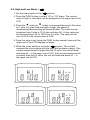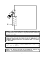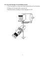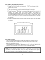
1
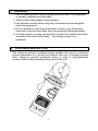
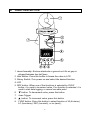
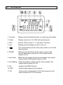
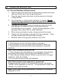
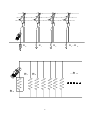
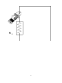
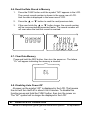
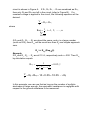
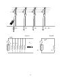
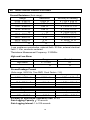
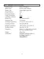
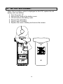
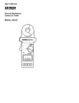
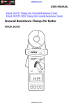
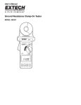
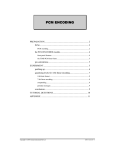
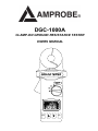
DGC-1000A CLAMP-ON GROUND RESISTANCE TESTER USERS MANUAL HOLD OFF FUNC REC EN 61010-2-032 CAT III 300V, CAT II 600V Pollution Degree 2 Definition of Symbols: Caution: Refer to Accompanying Documents Caution: Risk of Electric Shock Double Insulation Table of Contents I. WARNING ............................................................................................... 1 II. FEATURES DESCRIPTION .................................................................. 1 III. PANEL DESCRIPTION ......................................................................... 2 IV. LCD DISPLAY....................................................................................... 3 V. OPERATION INSTRUCTION ................................................................ 4 5-1. Ground Resistance Measurement ..................................................... 4 5-2. High and Low Alarm ( ) ............................................................... 7 5-3. Ground/Leakage Current Measurement ............................................ 9 5-4. Setting the Sampling Interval ........................................................... 10 5-5. Data Logging .................................................................................... 10 5-6. Read the Data Stored in Memory..................................................... 11 5-7. Clear Data Memory .......................................................................... 11 5-8. Cancel the Auto Power Off ............................................................... 11 VI. PRINCIPLE OF OPERATION ............................................................ 11 VII. ELECTRICAL SPECIFICATION ....................................................... 14 VIII. GENERAL SPECIFICATIONS ......................................................... 15 IX. BATTERY REPLACEMENT ............................................................... 16 I. WARNING 1. Use of rubber gloves is a good safety practice even if the equipment is properly operated and grounded. 2. Safety is the responsibility of the operator. 3. Use extreme caution when using the instrument around energized electrical equipment. 4. Do not attempt to use the ground tester to twist or pry the ground electrode or ground wire away from the equipment being grounded. 5. All metal objects or wires connected to an electrical system should be assumed to be lethal until tested. Grounding system is no exception. II. FEATURES DESCRIPTION The clamp-on ground resistance tester enables the users to measure ground resistance of a ground rod without the use of auxiliary ground rods. Clamp-on ground resistance tester is used in multi-grounded systems without disconnecting the ground under test. HO L OF D F FU NC RE C 1 III. PANEL DESCRIPTION HOLD OFF FUNC REC 1. Jaws Assembly: Enclose electrode or ground rod. No air gap is allowed between two half jaws. 2. Hold Button: Press this button to freeze the value in LCD 3. Rotary Switch: Turn power on and select the desired function. 4. LCD 5. REC button: When one of the functions is selected by FUNC button, it is used to increment value. If no function is selected, it is used to start data logging, or record one data point. 6. ▼ button: To decrement value, press this button 7. Jaws Trigger 8. ▲ button: To increment value, press this button 9. FUNC button: Press this button to select function of HI (hi alarm,) LO (low alarm), SEC (seconds), or no.(read,). 2 IV. LCD DISPLAY 1. Function Display current selected function or current record number. 2. Digits Display value from 0 to 9999 with decimal point. 3. Ohm Symbol will be shown in and alarm functions. 4. mA Display ground leakage current in mA or A 5. This symbol will be shown if the rotary switch is set at the alarm position. 6. NOISE: When ground resistance tester senses noise in the ground electrode or ground rod, this symbol will be shown in LCD 7. Jaw Open When the jaw is open during measurement, this symbol and the word OPEN will be shown in LCD. 8. Low Battery When the battery voltage is lower than required, this symbol will be shown in LCD. 9. NO. Indicate the READ function. 10. REC Indicate data logging is in progress. 11. AP If this symbol is displayed in LCD, that means the unit will be turned off in 4 to 6 minutes. 3 V. OPERATION INSTRUCTION 5-1. Ground Resistance Measurement 1. 2. 3. 4. 5. 6. 7. Open the jaws and make sure the jaws mating surfaces are clean and free of dust, dirt or any foreign substance. Snap the jaws closed a few times to let the jaws sit on the best mating position. Turn the power on, set the rotary switch at position. Do not clamp on to any conductor or open the jaws at this moment or during self-calibration. At power up, the clamp-on ground resistance tester will do the self-calibration for better accuracy. Users should wait for self-calibration to be complete. During the self-calibration, LCD will show CAL5, CAL4, CAL 3, CAL2, and CAL1. When the ground tester is ready, a beep sound will be heard. Clamp on to the electrode or ground rod to be measured. Snap the jaws closed a few times for better accuracy. Read the value of Rg (ground resistance) from LCD. Note: For better measurement, 1. Snap the jaws closed a few times before powering on. 2. Do not clamp on to any conductor at the moment of power up. 3. Snap the jaws closed a few times after clamping on to ground electrode. Note: If self-calibration does not stop, 1. That is because the self-calibration is not complete. Ground tester will continue the process until a proper self-calibration is done. 2. Check the jaw mating surfaces. If there is any dirt, dust, or foreign substance, clean the surfaces. 3. Do not open the jaws during self-calibration. Note: Noise present in the electrode or ground rod. If overly excessive current or 30V in ground rod exists, the symbol “NOISE” will be displayed on the LCD. In the presence of noise, the reading is no longer accurate. Note: If jaw is open during measurement, a symbol of OPEN will be displayed in LCD. 4 HOL D OFF FUN C REC RG R1 R2 ...R HO OFF LD R1 FU NC R 3 ...R R2 RE C RG 5 N N H O L O FF D FU N C R EC RG 6 5-2. High and Low Alarm ( ) position. 1. Set the rotary switch to the 2. Press the FUNC button to select “HI“ or “LO” alarm. The current value of High or Low alarm will be displayed on the upper row of the LCD. 3. Press the ▲ button or ▼ button to increment/decrement the value by 1 ohm. As users hold the button longer, the speed of incrementing/decrementing will become faster. The value can be increment from 0 ohm to 1510 ohm and then OL. Or the value can be decrement from OL to 1510 ohm to o ohm. The value will roll over to OL/0 if the current value is 0/OL. 4. Once the value is set, press the FUNC button several times until the upper row of the LCD displays no letters. 5. When the rotary switch is set to the position. The unit will compare the current value with the high and low alarm values. If the current measurement is larger than the HI value, the unit will beep and show HI -- in the upper row of LCD. If the current measurement is smaller than the LO value, the unit will beep and show LO – in the upper row of LCD. 7 HO L O FF D FU N C R EC R LOOP NOTE: If the HI value is set at OL, or the LO value is set at 0, the ALARM function will be disabled. So they are method to disable one of the HI or LO alarm. NOTE: The HI value can’t be smaller than the low value. And the LO value can’t be larger than the HI value. HI value will be adjusted to LO value plus 1 when roll-over occurs. The maximum value of LO value is HI value minus 1. NOTE: If data logging is progressing, sound of beeping will be disabled to save battery power. But the LCD still shows the warning letters of “HI—“ or “LO—“. NOTE: The values for the high and low alarm are stored in the memory. They are restored when the power is turned on. 8 5-3. Ground/Leakage Current Measurement 1. Turn the power on, and set the rotary switch at the mA or A position. 2. Clamp on to the electrode or ground rod. 3. Read the value of leakage current displayed in LCD. HO L O FF D FU N C R EC 9 5-4. Setting the Sampling Interval 1. Press the FUNC button until letters of upper row of LCD. “SEC” are shown in the 2. The unit shows the current sampling interval in seconds. 3. Press the ▲ or ▼ button to increment/decrement the value by 1 second. As users hold the button longer, the speed of incrementing/decrementing will become faster. The value can be incremented/decremented from 0 to 255 / 255 to 0 seconds. Value will roll over when the value of maximum 255/minimum 0 seconds is reached. 4. Press the FUNC button several times until the upper row LCD show no letters. 5-5. Data Logging The unit will start data logging if the REC button is pressed, and a symbol of REC will be shown in LCD. Data will be recorded at the specified sampling interval. Data logging will be stopped if the memory is full, or the unit detects the condition of low battery, or the REC button is pressed again. NOTE: If the sampling interval is set at 0 seconds, only one data is recorded. To record next data, users can press the REC button again. The record number is also displayed for about 1 seconds. 10 5-6. Read the Data Stored in Memory 1. Press the FUNC button until the symbol “NO” appears in the LCD. The current record number is shown in the upper row of LCD. And the data is displayed in the lower row of LCD. 2. Press the ▲ or ▼ button to read the next/previous data, 3. If the user holds the ▲ or ▼ button longer, the record number will be incremented/decremented faster. The record number will roll over when the last/first record is reached. 5-7. Clear Data Memory Press and hold the REC button, then turn the power on. The letters “CL” will appear indicating the memory is cleared. 5-8. Disabling Auto Power Off At power up the symbol “AP” is displayed in the LCD. That means the unit will turn itself off in about 4 to 6 minutes. To disable this function press and hold the FUNC button, then turn the power on. The “AP” symbol will no longer be displayed in the LCD. VI. PRINCIPLE OF OPERATION Below is a simplified typical ground distribution system. 11 Its equivalent circuit is shown in Figure A. If R1, R2, R3, ... Rn are combined as Req, then only Rg and Req are left in the circuit (refer to Figure B). If a constant voltage is applied to the circuit, the following equation will be derived. V Rg Req I where 1 Req , i 1, 2, ......, n 1 Ri If Rg and R1, R2, ... Rn are about the same, and n is a large number (such as 200), then Req will be much less than Rg and maybe approach zero. Rg >> Req (Req→0) Example: If Rg and R1, R2, ... Rn are all 10 , respectively and n = 200. Then Req by calculation equals Re q 1 1 1 1 ... 10 10 10 0. 05 Ω V Rg Req 10 0.05 10.05 Rg I In this example, we can see that as long as the number of multiple electrodes is large enough, the equivalent resistance is negligible with respect to the ground resistance to be measured. 12 HO OF LD F FUN C REC RG R1 R2 R 3 ...R Figure A R1 R2 R3 N FigureB ...R N RG 13 R eq VII. ELECTRICAL SPECIFICATIONS Ground Resistance (Auto range) : Range Resolution 0.025 - 0.250 0.002 0.250 - 1.000 0.02 1.001 - 9.999 0.02 10.00 - 50.00 0.04 10.01 - 99.99 0.04 100.0 - 200.0 0.4 200.1 - 400.0 2 400.0 - 600.0 5 600.1 - 1500 20 Accuracy of Reading1 ± 1.5% ± 0.05 ± 1.5% ± 0.05 ± 1.5% ± 0.1 ± 2.0% ± 0.3 ± 2.0% ± 0.5 ± 3.0% ± 1.0 ± 5.0% ± 5 ± 10% ± 10 ± 20% Loop resistance noninductive, external field < 50 A/m, external electrical field < 1 V/m, conductor centered. 2Resistance Measurement Frequency: 3.333KHz 1 High and Low Alarm High Alarm Lo Alarm Range 0 - 1510 0 - 1510 Resolution 1 1 Ground/Leakage Current (Auto range, 50/60 Hz, True RMS, Crest Factor < 3.0) Range Resolution Accuracy of Reading 0.200 - 1.000 mA 0.001 mA ± 2.0% ± 0.05 mA 1.00 - 10.00 mA 0.01 mA ± 2.0% ± 0.03 mA 10.0 - 100.0 mA 0.1 mA ± 2.0% ± 0.3 mA 100 - 1000 mA 1 mA ± 2.0% ± 3 mA (Auto range, 50/60 Hz, True RMS, Crest Factor < 3.0) Range Resolution Accuracy of Reading 0.200 – 4.000 A 0.001 A ± 2.0% ± 0.03 A 4.00 – 30.00 A 0.01 A ± 3.0% ± 0.03 A Accuracy of Resistance Calibration Plate: ±0.5% Data Logging Capacity:116 records Data Logging Interval: 1 to 255 seconds 14 VIII. GENERAL SPECIFICATIONS Conductor Size: 23mm (0.9”) approx. Battery Type: 9V IEC 6 LR61 (Alkaline) Display Type: 4 digits 9999 counts LCD Range Selection: Auto Overload Indication: OL Power Consumption: Low Battery Indication: 40mA Battery Life: 3000 measurements Sampling Time: 0.5 seconds Operating Temperature: 0C to 50C (14F to 122 F) Operating Humidity: Less than 85% RH Storage Temperature: -20C to 60C (-4F to 122 F) Storage Humidity: Less than 75% RH Dimension: 257mm (L) x 100mm(W) x 47mm(H) 10.1" (L) x 3.9"(W) x 1.9"(H) Weight: 640g/1.4lbs Accessories: Resistance Calibration Plate x 1 9V Battery (Installed) x 1 Users Manual x 1 Carrying Box x 1 15 IX. BATTERY REPLACEMENT When the low battery symbol is displayed on the LCD, replace the old battery with new battery. 1. Turn the power off. 2. Remove the screw of the battery cover. 3. Lift and remove the battery cover. 4. Remove the old battery. 5. Install a new 9V battery. 6. Replace the cover of battery and secure the screws. 1 2 7 11 10 6 3 20 16 LIMITED WARRANTY Congratulations! Your new instrument has been quality crafted according to quality standards and contains quality components and workmanship. It has been inspected for proper operation of all of its functions and tested by qualified factory technicians according to the long-established standards of our company. Your instrument has a limited warranty against defective materials and/or workmanship for one year from the date of purchase provided that, in the opinion of the factory, the instrument has not been tampered with or taken apart. Should your instrument fail due to defective materials, and/or workmanship during this one year period, a no charge repair or replacement will be made to the original purchaser. Please have your dated bill of sale, which must identify the instrument model number and serial number and call the number listed below: Repair Department ATP – Amprobe, TIF, Promax Miramar, FL 33025 Phone: 954-499-5400 Toll Free:800-327-5060 Fax: 954-499-5418 Website: www.Amprobe.com Please obtain an RMA number before returning product for repair. Outside the U.S.A. the local representative will assist you. Above limited warranty covers repair and replacement of instrument only and no other obligation is stated or implied. Miramar, FL 33025 17 Tel: 954-499-5400 Toll Free: 800-327-5060 Fax:954-499-5418 18