1
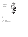
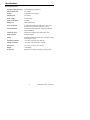
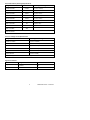
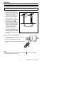
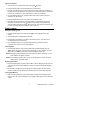
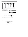
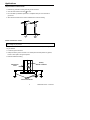
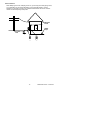
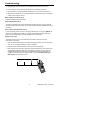
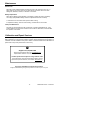
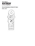
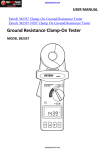
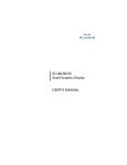
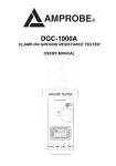
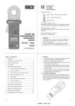
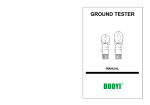
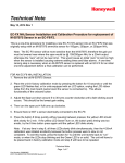
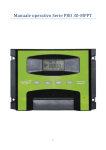
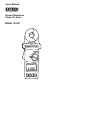
User’s Manual
Ground Resistance
Clamp On Tester
MODEL 382357
Warranty
EXTECH INSTRUMENTS CORPORATION warrants the basic instrument to be free of defects in parts and
workmanship for one year from date of shipment (a six month limited warranty applies on sensors and cables). If it
should become necessary to return the instrument for service during or beyond the warranty period, contact the
Customer Service Department at (781) 890-7440 EXTENSION 210 for authorization or visit www.extech.com for
more information. A Return Authorization (RA) number must be issued before any product is returned to
Extech. The sender is responsible for shipping charges, freight, insurance and proper packaging to prevent
damage in transit. This warranty does not apply to defects resulting from action of the user such as misuse,
improper wiring, operation outside of specification, improper maintenance or repair, or unauthorized modification.
Extech specifically disclaims any implied warranties or merchantability or fitness for a specific purpose and will not
be liable for any direct, indirect, incidental or consequential damages. Extech's total liability is limited to repair or
replacement of the product. The warranty set forth above is inclusive and no other warranty, whether written or
oral, is expressed or implied.
Introduction
Congratulations on your purchase of Extech’s 382357 Ground Resistance Tester. This
Clamp-on device allows the user to measure ground resistance without the use of auxiliary
ground rods. This device can only be used on multi-grounded systems. It is not necessary
to disconnect the ground under test. Proper use and care of this meter will yield years of
reliable service.
Safety
Only qualified technicians should operate this meter.
Use extreme caution when operating the meter near energized electrical equipment.
Do not attempt to use this meter to twist or pry the ground electrode or ground wire
away from grounded equipment.
All metal objects or wires connected to the electrical system under test should be
assumed to be lethal until tested. Grounded systems are no exception.
Ensure that the batteries are inserted correctly in the battery compartment.
Remove the batteries from the meter if the meter is to be stored for long periods.
WARNING: If the meter is used in a manner not specified by the manufacturer, the built
in protections provided by the meter may be impaired.
International Safety Symbols
This symbol, adjacent to another symbol or terminal, indicates the user
must refer to the manual for further information.
This symbol, adjacent to a terminal, indicates that, under normal use,
hazardous voltages may be present
2
Model 382357 Version 1.0 June 2004
Description
1.
Jaw Assembly
2.
Hold Button
3.
Rotary Selector Switch
4.
LCD Display
1
5.
Record Button
6.
▼(decrement) Button
7.
▲(increment) Button
8.
Function Button
9.
Measurement Trigger
2
3
9
4
5
8
7
6
Display Symbols
Ω
Ohms (resistance measurement)
mA, A
milli-amperes, Amperes (current measurements)
•)))
Hi Lo alarm position
NOISE
Excessive noise on the ground conductor or rod
Clamp jaws are not fully closed
Low Battery
REC
Indicates data logging in progress
NO.
Indicates the READ function
H
Hold function activated
3
Model 382357 Version 1.0 June 2004
Specifications
General Specifications
Resistance Test Frequency:
3.333 kHz (15mV rms approx.)
Max Conductor size
0.9” (23mm)
Display
4-digit (9999 count) display
Sampling rate
0.5 seconds
Power supply
One 9V battery
Power consumption
40mADC
Battery Life
3000 measurements
Temp. Coefficient
0.15 times the specified accuracy per C (from 39 to
o
o
64ºF (4 to 18 C) and 82 to 122ºF (28 to 50 C))
Current Overload
Protected to 100A Continuous; 200A for less than 60
seconds (50/60Hz)
Continuity check
Audible tone if reading is less than approx. 40Ω
Range selection
Automatic ranging
Safety
Meets the requirements for IEC1010-1 Category III 300V
and Category II 600 V
Operating conditions
14 to 122 F (0 to 50 C) with < 85% RH
Storage conditions
-4 to 122 F (-20 to 60 C) with < 75% RH
Dimensions
10.1 x 3.9 x 1.9” (257 x 100 x 47mm)
Weight
1.4lbs (640g)
Accessories
Resistance check plate, 9V battery, & carrying case
o
o
o
4
o
o
Model 382357 Version 1.0 June 2004
Ground Resistance (Autorange) Specifications
Range
Resolution
Accuracy (of reading)
0.025 to 0.250Ω
0.002Ω
± (1.5% + 0.05Ω)
0.250 to 1.000Ω
0.02Ω
± (1.5% + 0.05Ω)
1.001 to 9.999Ω
0.02Ω
± (1.5% + 0.1Ω)
10.00 to 50.00Ω
0.04Ω
± (1.5% + 0.1Ω)
50.01 to 99.99Ω
0.04Ω
± (1.5% + 0.5Ω)
100.0 to 200.0Ω
0.4Ω
± (1.5% + 1.0Ω)
200.1 to 400.0Ω
2Ω
± (5.0% + 5Ω)
400.0 to 600.0Ω
5Ω
± (10% + 10Ω)
600.1 to 1500Ω
20Ω
± 20%
Accuracy Note: Loop resistance non-inductive, external field < 50A/m, external electrical field <1 V/m,
conductor centered
Ground / Leakage Current Specifications
Range
Accuracy (% of reading)
0.200 to 1.000mA
± (2.0% ± 0.05mA)
1.00 to 10.00mA
± (2.0% ± 0.03mA)
10.0 to 100.0mA
± (2.0% ± 0.3mA)
100 to 1000mA
± (2.0% ± 0.3mA)
0.20 to 4.00A
± (2.0% ± 0.03A)
4.00 to 30.00A
± (3.0% ± 0.03A)
Notes: Auto-range, 50/60Hz bandwidth, True RMS sensing, Crest Factor < 3.0
High and Low Alarm
Range
Resolution
High Alarm
0-1500Ω
1Ω
Low Alarm
0-1500Ω
1Ω
5
Model 382357 Version 1.0 June 2004
Operation
Note: Ensure that the jaws are fully closed before testing.
Note: DO NOT clamp on to any conductor or open the clamp jaws during the start-up
self-calibration (self-cal is identified by the LCD counting down from CAL5 to CAL1).
Ground Resistance Measurements
1. Open the clamp jaws and check
that all surfaces are clean and free
of dust, dirt, or any foreign
substances. Clean if necessary.
2. Forcefully snap the clamp jaws
open and closed several times.
3. Turn the meter on by moving the
rotary switch to the ohms Ω
position. DO NOT interrupt the
start up procedure by opening the
clamp jaws or clamping around a
conductor. During self-calibration,
the meter will display CAL5,
CAL4, CAL3, CAL2 and CAL1.
T
Typical application
4. Once the start-up calibration
procedure is completed, the meter
will sound a beep. Clamp on to an
electrode or ground rod and read
the value of ground resistance on
the display.
Ground / Leakage Current Measurement
1. Turn the meter on by moving the rotary switch to
the mA or A position.
2. Clamp on to the electrode or conductor
3. Read the value of leakage current displayed on the
LCD.
HOLD
Press the HOLD button to freeze the reading in the display. H will appear in the display.
Press HOLD again to exit the function.
6
Model 382357 Version 1.0 June 2004
High and Low Alarm
1. Turn the meter on by moving the rotary switch to the •))) position.
2. Press the FUNC button to view and adjust the “HI” alarm value..
3. Press ▲ or the ▼ button to increase or decrease the value. Hold down the button to
increase the speed of adjustment. The value can be incremented from 0 to 1500 ohms
and then OL (overload). The value will roll over to 0 after OL is displayed.
4. Once the desired value is set, press the FUNC button a second time to view and
adjust the “LO” alarm value.
5. Press the FUNC button three more times to exit the setting mode.
6. The meter will now compare the measured resistance value with the high and low
limits when the meter is set to the •))) position. If the reading is larger than the HI
value, the meter will beep and display “HI” on the LCD. If the reading is lower than the
LO value, the meter will beep and display “LO” on the LCD.
Data Logging
Setting the Sampling Time
1. Press the FUNC button three times until the “SEC” symbol appears in the LCD
display.
2. The sampling rate is now displayed in seconds.
3. Press the▲ or the ▼ button to increase or decrease the value. The value can be
incremented from 0 to 255 seconds.
4. Once the desired value is set, press the FUNC button several times until the
characters in the upper row of the LCD disappear.
Recording Data
1. Press the REC button to start recording data at the specified sampling rate. The
“REC” symbol will appear on the top of the LCD display. To stop recording, press the
REC button. The “REC” symbol will no longer be displayed on the LCD.
NOTE: Data logging will automatically stop if the memory is filled (116 records), or if the
meter detects a low battery condition.
NOTE: If the sampling interval is set to 0, only one sample will be recorded. To record
another sample, press REC again.
Recalling Stored Data
1. Press the FUNC button four times until the “NO.” symbol is displayed on the LCD. The
current record number will be displayed in the top row and the data will be displayed
below it.
2. Press the ▲ or the ▼ button to step through and read the data in the next memory
location. Holding down the button will increase the speed of the incrementing value.
Clearing Data Memory
1. With the meter powered off, press and hold down the REC button while turning the
meter on. The “CL” symbol will appear on the display indicating that memory has been
cleared.
7
Model 382357 Version 1.0 June 2004
Measurement Principles
Typical multi-grounded distribution system
Rn
R2
Rg
R1
Req
If the parallel ground resistances,
R1, R2, R3,etc, up to Rn are combined
as Req, then only Rg and Req are
left in the circuit
I
V
Rg
If a constant voltage is applied to the circuit, the following equation applies:
V
= R g + Req
I
Req =
where:
1
, i = 1,2,...n
1
∑
Ri
If Rg and R1, R2, R3…Rn, are approximately the same, and n is large (200, for example),
then Req will be much less then Rg and may possibly approach zero.
Example:
If Rg and R1, R2, R3…Rn are all 10Ω respectively and n = 200, then Req by calculation
equals:
Req =
1
= 0.05Ω
1
1
1
+ + ...
10 10
10
V
= R g + Req = 10 + 0.05 = 10.05 → R g
I
8
Model 382357 Version 1.0 June 2004
Applications
Telephone-Electrical Ground Rods
1. Remove any protective covering from the ground conductor
2. Turn the meter switch to the Ohm Ω function.
3. Once the start-up calibration procedure is completed clamp on to an electrode or
ground rod.
4. Allow several seconds for the meter to settle and then note the reading.
Cellular Transmission Towers
WARNING: Use extreme care when making measurements around transmission towers;
High Voltage may be present.
The ground conductor should be located at the base of the tower, but your configuration
may be different.
1. Locate the ground conductor
2. Clamp around the ground conductor. You should place the clamp before any splices,
bonds or other splits in the ground system.
3. Read the measured reading.
Primary
Ground Conductor
Transmission
Tower
Cement Pad
Branch
Ground Conductors
9
Model 382357 Version 1.0 June 2004
Service Entrance
Note: Multiple ground rods, multiple grounds i.e. ground rod(s) and water pipe grounds,
or a combination may be present depending on the particular situation. In these
situations it is necessary to make your measurements between the service-entrance
neutral and all subsequent ground points.
Distribution
Panel
Water
Pipe
Ground
Rod
10
Model 382357 Version 1.0 June 2004
Troubleshooting
1. Snap the jaws open and closed two or three times before turning the meter on
2. Do not clamp on to any device during the power-up initialization sequence.
3. Snap the jaws two or three times after clamping on to the ground electrode or rod.
4. Slight amounts of drift may occur at high resistance measurements; this is normal and
should not be cause for concern.
Blank display or any failure mode
Replace the battery before proceeding.
Start-up Initialization Failure
The start-up calibration will continue indefinitely if the jaws are open or dirty. Check that
the jaws’ mating surfaces are clean. Do not open the jaws while the initialization sequence
is running.
Noise on the Ground Electrode or Rod
If noise is present (over 3A or 30V) on the ground electrode or rod, the word “NOISE“ will
appear on the display and readings can no longer be considered accurate. Before the
meter can be used accurately, the noise problem must be addressed.
Reference Test Loop
The reference test loop is a set of resistors that provides a means to check the
performance of the meter.
1. Open the measurement jaws and check that the mating surfaces are clean and free of
dust, dirt, or any foreign substances. Clean if necessary.
2. Clamp the meter around the reference loop as shown in the diagram.
3. Give the meter a few seconds to settle and read the measurement. The meter should
display approximately the same value as marked on the reference loop, taking into
consideration the accuracy listed in the specification chart. If the readings are not
similar to what is marked on the reference loop, consult the Trouble Shooting and
Maintenance sections of this manual.
11
Model 382357 Version 1.0 June 2004
Maintenance
General Care
Store the ground resistance tester and reference loop in its case when not in use. A
damp cloth may be used to clean any surface dirt from the meter. Never use harsh
detergents, abrasives, solvents, or cleaners on the meter.
Battery Replacement
When the low battery symbol appears on the display, replace the meter’s 9V battery.
Use a high quality alkaline battery whenever replacement becomes necessary.
1. Remove the two rear screws and open the meter housing.
2. Replace the battery, close the meter housing, and affix the two rear screws.
Clamp Jaw Maintenance
The jaws may be brushed clean with a toothbrush or similar soft-bristled brush. Care
must be taken to ensure that the contact fins are not bent or deformed, as this will affect
the operation of the meter.
Calibration and Repair Services
Extech offers repair and calibration services for the products we sell. Extech also provides
NIST certification for most products. Call the Customer Service Department for information on
calibration services available for this product. Extech recommends that annual calibrations be
performed to verify meter performance and accuracy.
Support line (781) 890-7440
Technical support: Extension 200; E-mail: [email protected]
Repair & Returns: Extension 210; E-mail: [email protected]
Product specifications subject to change without notice
For the latest version of this User’s Guide, Software updates, and other
up-to-the-minute product information, visit our website: www.extech.com
Copyright © 2004 Extech Instruments Corporation
All rights reserved including the right of reproduction in whole or in part in any form
12
Model 382357 Version 1.0 June 2004